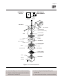
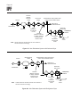
1
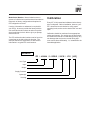
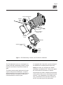
IPF
Field-Mount
Current-to-Pressure Transmitter
USER’S MANUAL
January 1992
© 1992 by Moore Industries-International, Inc.
No. 170-702-00 C
Table of Contents
Introduction
1
Description
1
Calibration
3
Installation
8
Operation
12
Maintenance
12
Troubleshooting
16
TRADEMARKS:
1. Telfon® is a registered trademark of the DuPont Corporation.
2. Loctite® is a registered trademark of Loctite Incorporated.
HR.
DELIVERY
8
4
UnitedStates/Canada
TOLLFREE
1-800-999-2900
United Kingdom
FREEPHONE
0800 525107
Australia
TOLLFREE
008 251928
Ask for the STAR Center
16650 Schoenborn Street
Sepulveda, California 91343, U.S.A.
Tel: (818) 894-7111 • Tlx: 65-1322
FAX: (818) 891-2816
CONNECT (MacNet): MIISEPULVEDA
1 Lloyds Court, Manor Royal, Crawley
W. Sussex RH10-2QU, United Kingdom
Tel: 0293 514488 • Tlx: 87667
FAX: 0293 536852
Moore Industries’ STAR* Center has a
wide variety of quality instrumentation
in stock and ready to ship.
• Signal Transmitters
• Temperature Transmitters
• P/I and I/P Converters
• Isolators and Converters
• Indicators and Displays
• Alarm Trips
• Integrators and Totalizers
• Power Transducers
• Instrument Power Supplies
• Racks, Rails and Enclosures
Most instruments can be customized
to meet your needs. Even then, you’ll
never have to wait more than a few days.
Moore Industries
3/18 Resolution Drive, Caringbah
New South Wales 2229, Australia
Tel: (02) 525-9177 • Tlx: 790-75914
FAX: (02) 525-7296
CENTER
* Support, Technical Assistance, and Repair (our Quick-Ship Facility)
IPF
Page 1
Introduction
The field-mount version of Moore Industries’ Currentto-Pressure Transmitter enclosed in an all-weather,
thermoplastic housing is called the IPF. It is a
rugged, two-wire transmitter whose design meets the
specifications for several types of water- and dusttight, and corrosion-resistance certifications. The
material used in the unit’s housing makes it ideal for
use under even the most arduous of environmental
conditions.
This manual contains the descriptive and instructional information needed to install, operate, and
maintain the IPF. It includes a brief explanation of
the unit model number, a table of its performance
and operational specifications, instructions for
calibration, information on installation and maintenance procedures, and checklist of troubleshooting
recommendations.
Appendix A consists of information on instrumentquality air and filtration, essential for optimum IPF
performance and reliability.
Notes and Cautions, where they appear in text or
illustrations, are used to call attention to practices
that otherwise may result in inconveniences for the
user (Notes) or damage to the IPF (Cautions).
Description
The IPF is used to effect changes in pneumatic
throughput pressure in a process loop. These
changes are proportional to, and based upon,
changes in a standard, process current input to the
unit. There are two options for input (current), and
eight for output (pressure).
The IPF housing is constructed of rugged, allweather, polyetherimide thermoplastic. It is designed
to meet the specifications of several third party,
industrial certifying agencies.
Contact your Moore Industries Sales Representative
for the most current list of IPF certifications and
approvals.
The unit has two electrical conduit dimension options; a 1/2-inch by 14 NPT female port (WP and
WPP) , and an M20 x 1.5 metric female port (WPM
and WPMP). Pneumatic connection fittings are
female, 1/4-inch by 14 NPT, standard.
NE-Type Units. IPF’s equipped with the NE Option
have a separate, external enclosure attached to the
main unit housing. This enclosure contains the
terminals for the connection of process current input.
The IPF can be installed in a surface-mount configuration (WP or WPM), or, with the optional hardware,
on 2-inch pipe (WPP and WPMP). The symmetrical
arrangement of the mounting holes in the base of the
unit housing provides for mounting on either horizontal or vertical piping.
The IPF housing affords the unit excellent protection
against shock, vibration, and corrosion. The unit is
also inherently immune to radio frequency and
electromagnetic interference (RFI/EMI).
Options
There are several options available for the IPF. The
following list provides an overview. A complete list,
including information on available mounting hardware and more data on the current IPF approvals
and certifications, is available from your Moore
Industries Sales Representative, or directly from the
factory.
FR1 Option – Coalescing Filter/Regulator w/Integral
Gauge. Maximum 4 scfm flow at 90 psig inlet
pressure. Removes particulate matter down to 0.01
micron in size. Scaled in 0-60 pounds per square
inch (psi) and 0-4 bars.
TF1 Option – Plastic Tube Fitting. For use with 1/4inch (O.D.) tubing. Option not available with FR1.
Table 1 lists the performance and operational
specifications for the IPF.
IPF
Page 2
Table 1. IPF Performance and Operational Specifications
Characteristic
Input
Output
Supply
Pressure
Specifications
Factory-configured.
4-20 mA into 200 , nominal.
10-50 mA
into 75 , nominal (available with 3-15 psig output units only).
Factory-configured.
0.2-1 bar (20-100 kPa)
1-0.2 bar (100-20 kPa)
3-15 psig
15-3 psig
3-16.6 psig
3-27 psig
Factory-configured.
20 psi (approximately 140 kPa, 1.4 bar) nominal.
35 psi (approximately 241 kPa, 2.41 bar) nominal. 35 psi required for 3-27 psig output units.
Filtered, regulated, instrument-quality air only. 20 psi units accommodate up to 30 psi without
damage. 35 psi units accommodate up to 40 psi without damage.
Controls
Span:
Zero:
Multiturn pot electronically adjusts full-scale output to 100% of rated span.
Multiturn adjustment screw mechanically provides offsets of ±3% of span.
Accuracy:
Error less than 0.5% of span, including the combined effects of linearity,
hysteresis, and repeatability. For 3-27 psig output units or 10-50 mA input units, error not to
exceed 1% of span. Linearity defined per SAMA standard PMC 20.1-1973.
Ambient Temperature Effect:
±0.1% of span per °C change within the rated ambient
temperature operating range (less than ±0.055% of span per °F change).
Performance
Supply Pressure Deviation Effect:
(0.3% per 0.1 bar).
Mounting Position Effect:
RFI/EMI Effect:
Step Response:
Pneumatic
Load
Environmental
Ratings
Weight
Maximum of 0.3% per 1.4 psig change
Negligible. Unit should be calibrated in final orientation.
±0.1% of span in field strengths of 10 V/m at frequencies of 20-500 MHz.
0.3 seconds into 100 ml (6 cu in) at 90% of span.
Air Capacity:
1.4 scfm (approximately 2.7 kg/hr)
Air Consumption:
0.1 scfm (approximately 0.2 kg/hr) dead-ended.
Recommended Ambient Temperature Operating Range:
Approximately 800 g (1 lb, 12 oz)
NOTE:
Refer to Installation Section for unit outline dimensions.
–20 to 60 °C (–4 to 140 °F).
IPF
Page 3
Model/Serial Number. Moore Industries uses a
system of individual unit model and serial numbers to
keep track of factory configuration and options for
IPF’s shipped or serviced.
If service information or assistance is required for
your IPF(s), be sure to provide the factory with the
unit model and serial numbers to assist our professional technicians in their effort to give you prompt,
efficient service.
The IPF serial and model numbers can be found on
a metal tag on the side of the unit housing. The
example outlines the significance of each field of
information in a typical IPF model number.
Calibration
Every IPF is fully tested and calibrated at the factory
prior to shipment. Before installation, however, your
IPF’s should be bench checked to verify proper
operating levels, and to set the desired unit zero and
span.
Calibration should be conducted in an appropriate
testing environment. By carrying out the procedures
at a technician’s bench or similar lab-type setup, any
unit damage that may have occurred during shipment can be discovered safely, i.e., isolated from the
intended application.
EXAMPLE
IPF / 4-20MA / 3-15PSIG / 20PSI / -FR1 [ WP ]
Unit Type
Input
Output
Supply Pressure
Options(s)
Housing
IPF
Page 4
Calibration Equipment
Table 2 lists the equipment required to calibrate the
IPF. This equipment is not supplied by Moore
Industries, but should be available in most labs or
maintenance areas.
Calibration Setup
The terminal labeled “+ I” is for connection of the
positive current input, and the terminal labeled “–I”
is for negative connections.
The two IPF controls are also located inside the unit
housing on the faceplate. They consist of a mechanical adjustment screw and an electronic potentiometer (pot), each accessed through holes in the
unit front panel. The following labels are used:
To prepare the IPF for calibration, disassemble the
unit as shown in figure 1, and connect it to your
calibration equipment as shown in figure 2, which
shows the calibration setup.
...controls the setting for unit zero.
...controls the setting for unit span.
Unit Connections and Controls. The IPF has two,
labeled terminals on its faceplate, located under the
top, protective cover of the housing. NE-type units’
terminals are enclosed in a separate, external subhousing labeled “TERMINAL CONNECTIONS” .
Table 2. IPF Calibration Equipment
Equipment
Current Source
DC Milliammeter
Air Supply
Air Pressure
Gauges
Pneumatic Test
Load
Screwdriver
Specifications
Calibrated, adjustable. Must be capable of discrete output levels within the appropriate, rated
range for the unit under test; 4-20 or 10-50 mA. Refer to model number and table 1.
Calibrated. Accuracy of ±0.1% (optional equipment)
Filtered, regulated, instrument-quality. Refer to appendix A of this manual for more detailed
specifications/filtration requirements.
Two calibrated gauges; #1 with accuracy of ±2%, #2 with accuracy of ±0.1%.
Calibrated. Volume of approximately 120 ml (75 in
Slotted-tip. Head width of 5 mm (0.1875 in), maximum.
3
), per IEC spec #770.
IPF
Page 5
SPAN POTENTIOMETER
TERMINAL
BLOCK
DETAIL
+I -I
ZERO
ADJUST SCREW
INTERNAL ASSEMBLY
REMOVAL TAB
RUBBER
RETAINING
STRAP
NE-TYPE
"TERMINAL CONNECTIONS"
COVER
N-TYPE
TERMINAL
BLOCK
DETAIL
Figure 1. IPF Disassembly, Controls, and Terminals for Calibration
The Zero adjustment screw is a cone-tipped, machined screw that mechanically provides a control
range for zero offsets of ±3-percent of rated unit
span.
The Span pot electronically adjusts unit full-scale
output to 100-percent of rated span. It requires
approximately 22 turns to move its wiper from one
extreme to the other, clockwise for maximum or
counterclockwise for minimum span.
It is equipped with a slip clutch to prevent damage if
the adjustment is turned beyond the wiper stop.
Always use clean, dry, instrument air, whether
calibrating or operating the IPF. Refer to the appendix of this manual for information on filtration.
All pneumatic lines used in calibration and operation
must be “blown down” prior to their being connected
to the IPF. Any condensation or oil residue in the
lines, if introduced into the pneumatic chambers of
the IPF, may result in poor unit performance.
IPF
Page 6
DC
MILLIAMMETER
–
+
+
+I
ADJUSTABLE
CURRENT SOURCE
IPF
–
–I
OUTPUT PORT
SUPPLY PORT
PRESSURE GAUGE
#2
(ACCURACY ±0.1%)
PRESSURE GAUGE
#1
(ACCURACY ±2%)
REGULATED
INSTRUMENT
AIR SUPPLY
PNEUMATIC
TEST LOAD
Figure 2. IPF Calibration Setup
1. Orient IPF as it will be positioned in the application. That is, if unit is to be oriented vertically
when installed, orient vertically to calibrate.
For NE-type units: Route wiring through
conduit opening in external sub-housing/terminal
block assembly.
2. With zero air input (supply off), connect 1/4-inch
pneumatic tubing between appropriate output
port of regulated instrument air supply and
calibrated pressure gauge #1 (accuracy of ±2%
of span). Connect another hose from gauge to
port labeled “SUPPLY” on IPF.
5. Connect positive lead of adjustable current
source to +I terminal of IPF. Connect negative
source lead to –I IPF terminal.
3. Connect 1/4-inch pneumatic tubing between IPF
port labeled “OUTPUT” and appropriate port of
pressure gauge #2 (accuracy of ±0.1% of span),
and from that gauge to appropriate pneumatic
load.
6. When connections are complete, apply 0% of
appropriate input current; 4 mA for 4-20 mA
units, or 10 mA for 10-50 mA units.
4. Run current source wiring through conduit
opening in housing, and to front panel of IPF.
A dc milliammeter may also be connected to
verify level of current input.
7. Apply appropriate, filtered, instrument-quality air
to supply line; 20 or 35 psi (40 kPa, or 1.4 bar).
Verify appropriate supply pressure by checking
Supply Pressure field of unit model number.
IPF
Page 7
8. Set span pot to approximate mid-scale (22 turns
in either direction, then approximately 11 turns in
the opposite direction).
9. Set zero adjustment screw fully clockwise, then
five turns counterclockwise.
10. Allow approximately 5 minutes for calibration
setup to stabilize.
Table 3 lists the values to be used during calibration.
Refer to the table when performing the following:
1. Check unit zero setting. Monitor reading of
pressure gauge #2 (output), and turn zero adjust
screw counterclockwise to lower output, clockwise to raise output. Set zero adjust screw so
that pressure output is at 0% of appropriate
range (±3%) when 0% input is applied.
2. Check unit span setting. Increase input to 100%
of rated span; 20 mA for 4-20 mA units, or 50 mA
for 10-50 mA units.
Calibration Procedure
To perform the recommended bench check for the
IPF, first perform the setup as described in the
preceding section. The calibration procedure consists of a basic check and adjustment of unit zero
and span, based on the reading of pressure gauge
#2 (accuracy of ±0.1%).
3. Monitor reading of pressure gauge #2 (output),
and adjust span pot so that reading is at 100% of
appropriate pressure range for your unit.
Check the values listed in Table 3.
Table 3. IPF Calibration Values
Verify by
Applying
25% of
Rated Input
Range*
Verify by
Applying
50% of
Rated Input
Range*
Verify by
Applying
75% of
Rated Input
Range*
At
0% of
Rated Input
Range*
(4 or 10 mA)
At
100% of
Rated Input
Range*
(20 or 50 mA)
Adjust Zero
until Gauge
#2 Reads:
Adjust Span
until Gauge
#2 Reads:
3-15 psig
3 psi
15 psi
6 psi
9 psi
12 psi
15-3 psig
15 psi
3 psi
12 psi
9 psi
6 psi
0.2-1 bar
0.2 bar
1 bar
0.4 bar
0.6 bar
0.8 bar
1-0.2 bar
1 bar
0.2 bar
0.8 bar
0.6 bar
0.4 bar
3-27 psig
3 psi
27 psi
9 psi
15 psi
21 psi
3-16.6 psig
3 psi
16.6 psi
6.4 psi
9.8 psi
13.2 psi
20-100 kPa
20 kPa
100 kPa
40 kPa
60 kPa
80 kPa
100-20 kPa
100 kPa
20 kPa
80 kPa
60 kPa
40 kPa
IPF Output
Configuration*
Gauge #2 will Read:
* Verify appropriate output configuration and percentage of rated input range against unit model number.
IPF
Page 8
4. Repeat steps 1 through 3 until IPF outputs 0% of
rated pressure range at 0% current input, and
100% of output pressure range at 100% current
input.
5. Verify the accuracy of your adjustments by
inputting the appropriate percent of span levels
listed in table 3.
Installation
The installation of the IPF is carried out in three
phases. The first phase is the physical mounting of
the unit. Next is the electrical connections phase,
and finally, pneumatic connections can be made. It
is strongly recommended that IPF’s be installed in
this order.
It is also strongly suggested that each unit be
calibrated according to the instructions in this manual
before being placed into service.
The IPF may be installed at any angle; either surface-mounted, or attached to pipe or round conduit.
Consideration should always be given to any requirement that may arise for front panel access, checking
the fittings, or reading the FR1 Option gauge and
draining its filter.
Closed Loop/Open Loop. The IPF should be
installed in a closed loop. A closed loop is the best
way to measure a control variable, to determine if a
deviation from a desired value exists, or to automatically provide feedback for actuator loading pressure.
An open loop has inherent limitiations that are not
consistent with precise control. Long term drift of the
loop dynamics, load fluctuations that require constant
adjustments of the actuator loading pressure, and
performance quality variations due to inconsistencies
between operating personnel are all problems
commonly associated with open loops. A controlled
variable cannot be directly measured in an open
loop; this prevents compensating adjustments to the
system input.
Mounting
Figure 3 gives the IPF’s outline dimensions. The
illustration also gives the dimensions of the available
FR1 Option hardware, recommended for most
installations, and the external sub-housing used for
the terminal block with NE-type IPF’s.
After placing the IPF in the desired location and
orientation, secure the housing with the optional pipe
mounting hardware, or other appropriate fasteners.
Figure 4 illustrates IPF mounting using optional pipe
mounting hardware. Note that the holes in the
mounting plate that comprises the base of the IPF
are symmetrical. This allows the unit to be installed
on either horizontal or vertical pipes.
The thermoplastic polyetherimide compound used in
the housing provides excellent protection from
chemical exposure. The housing is also unaffected
by electrolytic corrosion, as may be found in and
around salt water and many other industrial environments. Note, however, that this type of IPF is
designed, tested, and built for installation outdoors or
in well ventilated areas.
Refer to the WP/WPM housing data sheet in the
Moore Industries Product Catalog for more information regarding chemical environments compatibility,
or contact your Moore Industries Sales Representative for assistance.
Electrical Connections
Refer to figure 1 in the Calibration Setup Section of
this manual for instruction on the level of disassembly required to make the electrical connections to the
IPF.
Figure 5 is a generic diagram showing the unit’s
installation hookup.
To complete connections, route wiring through
conduit port, or through port in sub-housing for NEtype units, to terminal block, and use a slotted-tip
screwdriver with a maximum head width of 3 mm
(0.125 inch) to loosen the terminal screws.
IPF
Page 9
FR1 OPTION
94 mm
(3.68 in)
SQUARE
IP
69.8 mm
(2.75 in)
SQUARE
CURRENT TO
PRESSURE
TRANSMITTER
160 mm
(6.28 in)
9.14 mm (0.36 in)
DIAMETER
(4 MOUNTING HOLES)
APPROX.
145.8 mm (5.7 in)
WHEN
INSTALLED
TERMINAL
18.6 mm
(0.72 in)
CONNECTIONS
N-TYPE
24.2 mm
(0.94 in)
M20 X 1.5 THREADS
FOR WPM AND WPMP
HOUSINGS
36.7 mm
(1.4 in)
1/2 - 14 NPT THREADS FOR
–WP AND –WPP HOUSINGS
– OR –
M20 X 1.5 THREADS FOR
–WPM AND –WPMP HOUSINGS
N-TYPE
142.2 mm
(5.6 in)
1/4" NPT SUPPLY
PORT
SIDE PORT
FOR FR1
OPTION
29.2 mm
(1.1 in)
31 mm
(1.2 in)
1/4" NPT OUTPUT
PORT
Figure 3. IPF Outline Dimensions
IPF
Page 10
Figure 4. Mounting the IPF on Vertical and Horizontal Pipe
CURRENT
INPUT
4-20 OR 10-50 mA
+
+I
IPF
–
–I
OUTPUT
PORT
SUPPLY
PORT
PNEUMATIC
INSTRUMENT
OR
LOAD
REGULATED
INSTRUMENT
AIR SUPPLY
Figure 5. IPF Installation Hookup
IPF
Page 11
The terminals are comprised of compression-screw
sockets that accommodate 22-14 AWG wiring.
Connect positive lead (+) to terminal labeled “+I”,
and negative lead (–) to terminal labeled “–I”.
Tighten the terminal screws until snug.
To complete the IPF pneumatic connections, connect
the supply line to the 1/4-inch NPT female port on
the side of the unit labeled “SUPPLY”. Connect the
output line to the 1/4-inch NPT female port labeled
“OUTPUT”. Refer to the unit front panel which
identifies the IPF ports.
Use shielded, twisted-pair wiring for low-level input.
Ground the shielding wire as close as possible to the
installed IPF.
Seal all fittings with Teflon® tape, or equivalent.
“Pipe dope” is not recommended. If your application
environment prohibits the use of Teflon, contact
Moore Industries for assistance.
Pneumatic Connections
Always “blow down” (purge) all tubing and the
controlled device before connecting the IPF.
The final phase of IPF installation consists of connecting the pneumatic lines. Figure 5 also illustrates
these connections.
Figure 6 illustrates the recommended technique for
installing an IPF.
USE FLEXIBLE CONDUIT WHENEVER POSSIBLE
AVOID "STRAIGHT-LINE" CONNECTIONS
SUPPORT AND
CUSHIONING
BRACKET
FLAT
WASHERS
30 cm
(1 ft.)
MAXIMUM
Figure 6. An Example of a Typical IPF Installation
SUPPORT HEAVY
COMPONENTS
INDEPENDENTLY
IPF
Page 12
Recommendations are:
•
•
Use flexible or semi-flexible, plastic, pneumatic
tubing and plastic fittings, if possible.
Provide clip- or bracket-type support at 30 cm
(1 ft) intervals, and provide independent support
for any components or equipment installed in the
lines. Use cushioning brackets to dampen
vibration, if possible.
•
Avoid “straight-line” connections.
•
Provide auxiliary support for the filter/regulator (if
equipped), especially in areas where shock and
vibration are prevalent.
•
Do not over-tighten the fittings. A torque of 10 to
15 N•m (7.4 to 11.1 ft/lbs) is adequate.
Filters. The IPF requires filtered, dry, regulated,
instrument-quality air to prevent clogging, and to
ensure extended periods of maintenance-free
operation. Moore Industries suggests the following
levels of filtering protection:
•
Pre-filter – A general purpose “rough” filter, used
to reduce particulate matter to 5 microns in size.
Also removes bulk liquids. Although not required, this filter is especially recommended to
protect the 0.01 micron final filter when used.
•
Final Filter – A second, final filter is recommended, to remove particulate matter in sizes
down to 0.01 micron. This filter removes virtually
all condensable liquids from the air stream as
well.
•
Filter/Regulator Module Option – A combined
filter/regulator assembly, the FR1 Option, offered
as an accessory for the IPF, removes particles
down to 0.01 micron, supplying regulated,
instrument-quality air to the unit. This spacesaving module is affixed to the IPF supply port,
and comes with a pressure gauge scaled in both
psi (0-60) and bars (0-4).
Operation
Once its calibration has been checked or adjusted,
and the unit has been installed properly, the IPF
operates unattended. It requires only a minor
periodic maintenance procedure, detailed in the next
section of this manual.
Remember that if an IPF is installed in an open loop,
it may appear to drift over extended periods of time,
due to the lack of corrective feedback.
If the unit is determined to be the cause of a loop
irregularity, carry out the maintenance procedure in
the next section of this manual. If problems persist,
refer to the Troubleshooting Section.
Instrument-quality Air. Air from the application
continuously flows through the IPF during operation.
Depending upon the purity of the air supply, the
unit’s internal assembly may have to be removed
and cleaned at comparatively short intervals to
ensure continued optimum performance.
Initially, random checks can help establish a satisfactory maintenance interval geared to the user’s air
supply cleanliness. Refer to the next section for
instruction on the disassembly and cleaning of the
IPF.
Maintenance
Before beginning IPF maintenance, the unit must be
removed from its application. It is strongly recommended that the maintenance procedures be performed in a clean, controlled environment, such as at
a technicians’ bench, in a laboratory, etc.. Several
internal parts are small and precision-machined;
easily lost or damaged if an attempt is made to
perform maintenance in the field.
After maintenance, each IPF should be recalibrated
before it is returned to service. Refer to the Calibration Section of this manual for instructions.
IPF
Page 13
You Will Need...
Unit Disassembly
To perform the basic maintenance procedure for the
IPF, refer to table 4, which lists the equipment
required. These materials are not supplied by Moore
Industries, but should be available in maintenance
areas prepared to perform this type of procedure.
To disassemble the IPF for maintenance/cleaning,
remove the protective top cover in the same manner
as was carried out in the calibration setup. Unscrew
the two Phillips-head screws from the faceplate, and
remove it.
If this equipment is not available, your facility may
not be qualified to perform the operations described
in this section. Contact Moore Industries’ Customer
Service Department for more information.
For NE-type IPF’S . The wires from the external
terminal block to the internal sub-assemblies must be
cut to perform the maintenance/cleaning. Cut the
wires as close to their butt connectors as possible.
Table 4. IPF Maintenance Equipment
Equipment
Instrument
Quality Air or
Nitrogen Supply
White, Bond
Paper
Cotton Swabs
Trichloroethane
(TCE)
Isopropyl Alcohol
Syringe
Screwdriver
Probe
Cleaning Wire
Hex Keys
Removeable
Thread-locking
Compound
Specifications/Notes
Reduced to between 20 and 30 psig, and fitted with a hose and fine tip or nozzle.
Clean, undyed, and unlaminated.
Clean, general utility swabs for use in cleaning surfaces and absorbing excess solvent
and alcohol.
Rho-Tron-TPC-400 or equivalent
Clean, general purpose flushing solution.
Or similar mechanism for injecting alcohol into small orifices.
Slotted-tip. Head width of 5 mm (0.1875 in), maximum.
Technician’s tool for manipulation of very small parts.
0.005-inch diameter, maximum.
One 4 mm, standard;
One 3/32 in, minimum length 5.5 in. Ball-tipped head recommended;
One 5/32 in, standard
Loctite® #242 or equivalent removeable threadlocker.
IPF
Page 14
Take the internal assemblies out of the housing by
grasping plastic removal tab and pulling straight out,
away from housing base. Apply steady pull, disengaging the pneumatic fittings from their ports in the
housing base.
Separate sub-assemblies by removing the single,
slotted-head screw in the side of section #1 of the
pneumatic block, which is shown in figure 7.
Cleaning the Mechanical
Subassembly
1. Place subassembly on work surface with zero
screw and span pot down.
2. Use syringe to fill flapper air passage with
trichloroethane (TCE). See figure 7.
3. Clean nozzle air passage by gently passing
cleaning wire back and forth through opening in
subassembly base.
4. Soak several small strips of clean paper in TCE.
5. Set subassembly on its side, and slide one strip
between nozzle and flapper. Carefully apply
slight pressure to flapper until it rests against
nozzle with soaked paper in between.
6. Maintain pressure while pulling paper out.
Repeat with other strips of paper until no residue
is transferred to paper.
7. Inspect air passage O-ring. If damaged, contact
Moore Industries’ Customer Service Department
for replacement.
8. Use instrument air supply to dry and generally
“blow out” subassembly. Put small amount of
alcohol in air passage, and set subassembly
aside.
Cleaning the Pneumatic Block
Refer to figure 7 to disassemble the IPF pneumatic
block, and when performing the following:
1. Place block on work surface with its two sockethead screws facing up. Use screwdriver to mark
one side of block with several small scratches for
use when re-assembling parts.
2. Dip cleaning wire in TCE, and use it to clean
orifice #1, the air passage between block and
mechanical subassembly (see figure 7).
Flush orifice with alcohol after cleaning.
3. Remove two socket-head screws that hold the
pneumatic block together. Separate section #1
from block.
4. Use swabs dipped in TCE to clean internal
surfaces, and to remove any dirt particles or oil.
Flush all parts with alcohol after cleaning.
5. Push cleaning wire dipped in TCE through small
orifices on underside of section #1, in center
opening and along outside edge. Use syringe
filled with alcohol to flush openings.
Set section #1 aside.
6. Remove spring, disk, and diaphragm from top of
section #2. Inspect each for deterioration and
dirt. Use compressed air to blow off all parts.
7. Remove diaphragm from bottom surface of
section if necessary.
8. Push cleaning wire dipped in TCE through brass
fitting in center of section.
9. Clean small orifices along edge of section (top
and bottom) with cleaning wire, and flush with
alcohol syringe.
IPF
Page 15
PNEUMATIC
BLOCK
MECHANICAL
SUB-ASSEMBLY
NOZZLE
FLAPPER
SECTION #1
AIR PASSAGE
UPPER SPRING
(HEAVY GAUGE WIRE)
HOLE
PLASTIC DISK
UPPER RUBBER
DIAPHRAGM
ROLL IS UP
ROLL IS DOWN
BRASS
FITTING
SECTION #2
MIDDLE RUBBER
DIAPHRAGM
HOLE
HOLE
RESTRICTOR
SECTION #3
LOWER RUBBER
DIAPHRAGM/DISK
HOLE
SECTION #4
SUPPLY
SCREEN
Figure 7. IPF Internal Assemblies
10. Use swabs dipped in TCE to clean all surfaces.
11. Repeat cleaning/flushing procedure for orifices
and surfaces of section #3.
12. Remove integrated diaphragm/fitting from
section #4.
13. Clean orifices and surfaces on section as before.
IPF
Page 16
Check to make sure that the spring is in good
condition.
14. Locate supply port air filter screen on the pneumatic block.
Remove filter screen with needle, and flush with
TCE. Rinse with alcohol, and set aside to dry.
Re-assembly
1. Dry all parts of both the pneumatic block and the
mechanical subassembly with the specified air or
nitrogen supply. Make sure all parts are clean
and dry.
2. Use scratch markings made earlier to make sure
that each section of pneumatic block is oriented
properly, and use small socket-head screws to
secure re-assembled block. Tighten screws to
between 35 and 45 N•m of torque (26 to 33 footpounds).
3. Line up pin on section #1 of pneumatic block with
hole on base plate of mechanical subassembly.
4.
Place a small amount of thread-locker on the
threads of the slotted-head screw used to hold
the pneumatic block and mechanical subassembly together, and secure two subassemblies to
each other with the screw. Make sure screw is
as tight as possible.
5. Slide internal assembly into housing, being
careful not to crimp or pinch the current wiring,
and mate fittings in housing with ports on pneumatic block of internal assembly. Press down
until locked into place.
NOTE for NE-TYPE IPF’S:
Refer to Figure 8. The wiring between the
terminal block and the unit front panel, cut during
disassembly, must be rejoined using an AWG
#24-20 butt connector and heat shrink tubing
(available from Moore Industries). Use of nonspecified connectors invalidates the group N
certification.
POSITION HEAT SHRINK AS SHOWN.
DO NOT PINCH WIRING
BUTT CONNECTOR
DETAIL
HEAT SHRINK
TUBING
Figure 8. Re-wiring the NE-TYPE IPF
IPF
Page 17
To re-connect current wiring in N-type IPF’s,
connect the wires with the same color (black-toblack, and red-to-red). Use a crimping tool to
secure the connection.
6. Reseat IPF faceplate, and secure it using the
Phillips-head screws, and re-secure the top
cover of the housing.
If a problem is suspected with the IPF, review the
following steps:
1. Verify that bench instruments used to take
measurements have the proper range and
accuracy and are within current certification
period limits.
7. Calibrate unit. Refer to Calibration Section of
this manual.
2. If a change in the relationship between the input
and output is detected, attempt a re-calibration of
the IPF.
Drain Check. System filters have automatic drains,
which depend on the fluctuation of system pressure
to induce drainage. A stable system may not drain
efficiently.
3. If the response time lengthens, or if the span
drops, this may indicate a blockage due to air
supply contamination. Follow the instructions in
the Maintenance Section of this manual.
Periodically check for clogs, and drain system’s
filters by pushing the drainage valve with a small
probe or wire.
Troubleshooting
Many components of the IPF have been thermally
aged, tested, and selected using a computer-aided
design program. This usually makes field repair
unnecessary.
It is therefore recommended that any properly
maintained unit found to be performing below
specifications be returned to the factory in accordance with the instructions found on the back cover
of this manual.
The Zero Adjust Screw. This screw has a flange to
prevent its being turned too far counterclockwise
during adjustment. Forcing the screw past the point
at which its flange comes into contact with the unit
front panel could disengage it from the internal
assembly.
If this happens, disassemble the IPF as described in
the Maintenance Section of this manual.
Visually inspect the screw, and if serviceable, hold
down the flapper arm, and turn the screw clockwise
until its pin is in a position to hold the arm.
Refer to the Calibration Section of this manual, and
perform a unit recalibration.
Declaration of Conformity
EMC Directive 89/336/EEC
Manufacturer’s Name:
Manufacturer’s Address:
Moore Industries-International, Inc.
16650 Schoenborn Street
North Hills, CA 91343-6196
USA
Declares that the product(s):
Product Name:
IPF, IPT, IPX, IPH
MODEL
Model Number(s):
IPF
IPT
IPX
IPH
/
INPUT
*
*
*
*
/
OUTPUT
/
*
*
*
*
POWER
*
*
*
*
/
OPTIONS
-CE*
-CE*
-CE*
-CE*
/
HOUSING
*
*
*
*
* Indicates any input, output, supply pressures, option and housing as stated on the product
data sheet.
Conforms to the following EMC specifications:
EN61326-1, 1998, Electromagnetic Compatibility requirements for electrical equipment for control use.
Supplemental Information:
None.
January 11, 2005
Date
______________________________
Fred Adt
Quality Assurance Director
_____________________________________
Robert Stockham
Moore Industries-International, Inc.
European Contact: Your Local Moore Industries Sales and Service Office
Appendix A
Instrument Air and
Filtration
The selection and use of a good air filtration system
is essential in ensuring optimum performance of
pneumatic instrumentation and devices. Most users
find that it is much less expensive and troublesome
to design a system that includes a good air filtration
than to deal with downtime and repairs later. The
cleaner the air, the longer the time before servicing
will be needed.
Obtaining good instrument-quality air involves
removing solids, oil, and water after compression.
Oversizing elements helps to avoid performance
aberrations, and should reduce the need for periodic
maintenance. Redundancy should be used where
possible to avoid shutdown during maintenance.
The IPF is available with an optional coalescing filter/
regulator module, the FR1 Option, that combines a
0.01 micron air filter and a miniature supply-line
regulator. The unit has a 1/4-inch NPT female port
and a 4 scfm maximum flow at 90 psig inlet pressure.
It is furnished with an integrally mounted pressure
gauge scaled in both psi (0-60) and bars (0-4).
The Problems
Oil: Oil is the most common problem in compressed
air instrument systems. A coalescing filter removes
sub-micron liquid oil droplets from the air, and is
usually supplied with an automatic drain.
The filter works by trapping oil and water droplets in
a bed of microfibers. Droplets run together at fiber
cross-over points, form large liquid drops, and are
forced by air flow to a drain. A filter system consisting of a general purpose first-stage filter (about 5
micron) and a high-efficiency coalescing final filter is
recommended to obtain contaminant-free air.
The exact location of the first-stage filter in the loop
is not important; it can be located just ahead of each
final filter, or a single first-stage filter can be located
on a main line to protect a number of final filters on
branch lines. Each final filter (coalescing) should be
located just ahead of each pressure regulator.
IPF
Page A1
Water: The amount of water in an air system
depends on temperature, pressure, and the relative
humidity of the air. The amount of contamination,
therefore, tends to vary widely with geographic
location and weather.
To obtain intrument-quality air, sufficient water must
be removed to lower the dew point of the air to a
temperature below ambient. The dew point (at line
pressure) is expressed as the temperature at which
any moisture in the system begins to condense.
Water may be removed using a number of techniques, including coalescing filters, refrigeration
dryers and desiccant-type dryers. Care must be
taken in the selection and location of the filter,
because cooling, downstream of the filter, can cause
more condensation of water.
Typically, a coalescing filter should be installed
immediately upstream of the pressure regulator. In
this way the filter removes most of the water before
the air enters the regulator. Air leaving the regulator
then continues to dry due to expansion.
Solids: Random solid dirt, such as pipe scale and
rust, is occaisionally a problem in compressed air
instrument systems. A good filter will remove these
solids. However, if there is a desiccant dryer in the
line, a high-efficiency sub-micron filter is recommended for removing the highly abrasive sub-micron
particles produced by the dryer. This sort of filter is
desirable in any system, and is often a feature of
coalescing filters.
For systems subjected to freezing temperatures, the
portion of the system that runs outdoors should have
a dryer installed. The dryer reduces the dew point
below the lowest expected outdoor temperature.
A desiccant dryer is used upstream from a coalescing filter to keep the dryer from being damaged by oil
or from being overloaded with excessive condensed
water. Another high-efficiency coalescing filter is
recommended downstream of the dryer, to remove
desiccant particles.
Figures A1 and A2 illustrate typical non-redundant
systems with multiple branch lines. They both work
in any environment above freezing and differ only in
the placement of the first-stage, general purpose
filter.
IPF
Page A2
5 MICRON
GENERAL
PURPOSE
FILTER
COOLER
DESICCANT
DRYER
EXTEND BRANCH LINE(S) ABOVE MAIN
LINE TO AVOID PASSING LIQUIDS
MAIN LINE TO
OTHER BRANCHES
COMPRESSOR
D
HIGH –
EFFICIENCY
COALESCING
FILTER
RECEIVER
PRESSURE
REGULATOR
5 MICRON
GENERAL PURPOSE
FILTER(S), ONE MAIN
OR MULTIPLE ON
BRANCH LINES
NOTE:
All Filters should have automatic drains and service indicators to
show when elements need changing.
PURIFIED AIR
TO IPF’S
0.01 MICRON
HIGH
EFFICIENCY
COALESCING
FILTER
KEEP
SHORT
Figure A1. Non-Redundant System with Desiccant Dryer
COOLER
REFRIGERATION
DRYER
EXTEND BRANCH LINE(S) ABOVE MAIN
LINE TO AVOID PASSING LIQUIDS
MAIN LINE TO
OTHER BRANCHES
COMPRESSOR
D
PRESSURE
REGULATOR
RECEIVER
5 MICRON
GENERAL PURPOSE
FILTER(S), ONE MAIN
OR MULTIPLE ON
BRANCH LINES
NOTE:
All Filters should have automatic drains and service indicators to
show when elements need changing.
PURIFIED AIR
TO IPF’S
0.01 MICRON
HIGH
EFFICIENCY
COALESCING
FILTER
Figure A2. Non-Redundant System with Refrigerator Dryer
KEEP
SHORT
IPF
Page A3
Note that not all gauges, valves, and differential
pressure indicators (for filter service monitoring) are
not shown.
It is recommended that filters with integral service life
indicators or differential pressure indicators be used
to help ensure proper servicing. Use redundancy in
a filtering scheme to preclude any necessity for
shutdown during servicing.
Note that the systems depicted in the figures differ in
the method used to remove water. The use of a
desiccant dryer, as in figure A2, requires both
upstream and downstream filtration to prevent oil
contamination of the desiccant, as well as to prevent
desiccant fines from introducing new contamination.
ISA Specifications
The Instrument Society of America standard ISAS73, 1975 (ANSI MC11.1-1975) comprises the air
quality requirements for instrument-grade air for use
in pneumatic applications.
Although ISA specifications call for particle size not
to exceed 3 microns, and oil content not to exceed 1
ppm, coalescing filters are readily available that
remove particles down to sub-micron sizes (as small
as 0.01 micron), while also removing oil to below
0.01 ppm.
Moore Industries filters that exceed ISA specifications provide very inexpensive protection. Contact
your Sales Representative for more information.
RETURN PROCEDURES
To return equipment to Moore Industries for repair, follow these four steps:
1. Call Moore Industries and request a Returned Material Authorization (RMA) number.
Warranty Repair –
If you are unsure if your unit is still under warranty, we can use the unit’s serial number
to verify the warranty status for you over the phone. Be sure to include the RMA
number on all documentation.
Non-Warranty Repair –
If your unit is out of warranty, be prepared to give us a Purchase Order number when
you call. In most cases, we will be able to quote you the repair costs at that time.
The repair price you are quoted will be a “Not To Exceed” price, which means that the
actual repair costs may be less than the quote. Be sure to include the RMA number on
all documentation.
2. Provide us with the following documentation:
a) A note listing the symptoms that indicate the unit needs repair
b) Complete shipping information for return of the equipment after repair
c) The name and phone number of the person to contact if questions arise at the factory
3. Use sufficient packing material and carefully pack the equipment in a sturdy shipping
container.
4. Ship the equipment to the Moore Industries location nearest you.
The returned equipment will be inspected and tested at the factory. A Moore Industries
representative will contact the person designated on your documentation if more information is
needed. The repaired equipment, or its replacement, will be returned to you in accordance with
the shipping instructions furnished in your documentation.
WARRANTY DISCLAIMER
THE COMPANY MAKES NO EXPRESS, IMPLIED OR STATUTORY WARRANTIES (INCLUDING ANY WARRANTY OF MERCHANTABILITY OR OF FITNESS
FOR A PARTICULAR PURPOSE) WITH RESPECT TO ANY GOODS OR SERVICES SOLD BY THE COMPANY. THE COMPANY DISCLAIMS ALL WARRANTIES ARISING FROM ANY COURSE OF DEALING OR TRADE USAGE, AND
ANY BUYER OF GOODS OR SERVICES FROM THE COMPANY ACKNOWLEDGES THAT THERE ARE NO WARRANTIES IMPLIED BY CUSTOM OR
USAGE IN THE TRADE OF THE BUYER AND OF THE COMPANY, AND THAT
ANY PRIOR DEALINGS OF THE BUYER WITH THE COMPANY DO NOT IMPLY THAT THE COMPANY WARRANTS THE GOODS OR SERVICES IN ANY
WAY.
ANY BUYER OF GOODS OR SERVICES FROM THE COMPANY AGREES
WITH THE COMPANY THAT THE SOLE AND EXCLUSIVE REMEDIES FOR
BREACH OF ANY WARRANTY CONCERNING THE GOODS OR SERVICES
SHALL BE FOR THE COMPANY, AT ITS OPTION, TO REPAIR OR REPLACE
THE GOODS OR SERVICES OR REFUND THE PURCHASE PRICE. THE
COMPANY SHALL IN NO EVENT BE LIABLE FOR ANY CONSEQUENTIAL OR
INCIDENTAL DAMAGES EVEN IF THE COMPANY FAILS IN ANY ATTEMPT
TO REMEDY DEFECTS IN THE GOODS OR SERVICES , BUT IN SUCH CASE
THE BUYER SHALL BE ENTITLED TO NO MORE THAN A REFUND OF ALL
MONIES PAID TO THE COMPANY BY THE BUYER FOR PURCHASE OF THE
GOODS OR SERVICES.
United States • [email protected]
Tel: (818) 894-7111 • FAX: (818) 891-2816
Australia • [email protected]
Tel: (02) 8536-7200 • FAX: (02) 9525-7296
© 2007 Moore Industries-International, Inc.
ANY CAUSE OF ACTION FOR BREACH OF ANY WARRANTY BY THE
COMPANY SHALL BE BARRED UNLESS THE COMPANY RECEIVES
FROM THE BUYER A WRITTEN NOTICE OF THE ALLEGED DEFECT OR
BREACH WITHIN TEN DAYS FROM THE EARLIEST DATE ON WHICH THE
BUYER COULD REASONABLY HAVE DISCOVERED THE ALLEGED DEFECT OR BREACH, AND NO ACTION FOR THE BREACH OF ANY WARRANTY SHALL BE COMMENCED BY THE BUYER ANY LATER THAN
TWELVE MONTHS FROM THE EARLIEST DATE ON WHICH THE BUYER
COULD REASONABLY HAVE DISCOVERED THE ALLEGED DEFECT OR
BREACH.
RETURN POLICY
For a period of thirty-six (36) months from the date of shipment, and under
normal conditions of use and service, Moore Industries ("The Company") will
at its option replace, repair or refund the purchase price for any of its manufactured products found, upon return to the Company (transportation charges
prepaid and otherwise in accordance with the return procedures established
by The Company), to be defective in material or workmanship. This policy
extends to the original Buyer only and not to Buyer's customers or the users
of Buyer's products, unless Buyer is an engineering contractor in which case
the policy shall extend to Buyer's immediate customer only. This policy shall
not apply if the product has been subject to alteration, misuse, accident, neglect or improper application, installation, or operation. THE COMPANY
SHALL IN NO EVENT BE LIABLE FOR ANY INCIDENTAL OR CONSEQUENTIAL DAMAGES.
Belgium • [email protected]
Tel: 03/448.10.18 • FAX: 03/440.17.97
The Netherlands • [email protected]
Tel: (0)344-617971 • FAX: (0)344-615920
China • [email protected]
Tel: 86-21-62491499 • FAX: 86-21-62490635
United Kingdom • [email protected]
Tel: 01293 514488 • FAX: 01293 536852
Specifications and Information subject to change without notice.