1
SWISH
ER OWNER'S/OPERATOR'S
E4--$3000
MAN UAL
FR|MMER
E4-$3000
Minimize the risk of injury to yourself and others!
Read this manual and familiarize yourself with the
contents. Always wear eye and hearing protection
when operating this unit.
Part Number
81950
Rev.12/07
introduction
Attention
Statements
The Swisher E4-$3000 hand held power
equipment has been designed and built to
deliver superior performance and reliability
without compromise to quality, comfort,
safety or durability.
Swisher engines represent the leading edge
of high-performance
engine technology, delivering exceptionally high power with remarkably
low displacement and weight. As an owner!operatoL you'll soon discover for yourself why
Swisher is simply in a class by itseli!.
Throughout
this manual
tion statements".
are special
"attenoperators manual,
Failureand
to do
so could
Read
follow
this
result in serious injury.
protection at all times
duringeye
theand
operation
Wear
hearing
_WARN|NG!
of this unit.
A statement preceded by the triangular attention symbol and the word
"WARNING" contains information that
should be acted upon to prevent
ous bodily injury.
Keep bystanders
at least 50 feet (15 m)
away during operation.
seri_
CAUT|ON!
The information contained in this owner's/
operator's
manual describes
units available at the time of publication.
Swisher reserves the right to make
changes to products without prior notice, and
without obligation to make alterations to units
previously manufactured.
_
California to cause cancer, birth defects
or other reproductive harm.
Contents
I_6E
Attention
Statements
Safety Information
.................................
2
......................................
3
Safety Labels ...............................................
4
Product
5
Description
Specifications
Assembly
Starting
Stopping
...................................
..............................................
and Adjustments
.......................
Fuel .................................................
the Engine
5
6
9
the Engine ....................................
9
................................
10
Idle ..............................
10
Adjusting
Engine
Checking
Unit Condition
Shoulder
Strap ..........................................
Cutting
.........................
Grass with a Trimmer
Head
11
11
...... 11
Maintenance
.............................................
12
Long Term
Storage ..................................
15
Troubleshooting
Emission
A statement preceded by the word
"IMPORTANT"
is one that possesses
special significance.
WARN|NG!
The engine exhaust from this product
contains chemicals known to the State of
Engine
A statement preceded by the word
"CAUTION" contains information that
should be acted upon to prevent mechanical damage.
Guide ...........................
System Warranty
.....................
16
18
A statement preceded by the word "NOTE"
contains information that is handy to know
and may make your job easier.
eware of thrown or
ricocheted objects.
blade unless the unit is equipped
with
a Swisher-approved
Do not
operate this unit with a
handlebar or barrier.
_
operating this unit with a blade,
A lways
harness
is also
recommended
wear
a harness
when
when using trimmer line.
lf unit is used as a brushcutter,
beware of blade thrust, A jammed
blade can cause the unit to jerk
suddenly and may cause the
operator to lose control of the unit.
"
0
"
'
The operational procedures described in
this manual are intended to help you get the
most from this unit as well as to protect you
and others from harm. These procedures
are guidelines for safe operation under most
conditions, and are not intended to replace
any safety rules and/or laws that may be
in force in your area. If you have questions
regarding your E4-$3000, or if you do not
understand something in this manual, contact Swisher Inc. at (800) 222-8183, or go
to www.swisherinc.com for assistance. You
may also contact Swisher at the address
printed on the back of this Manual.
General
Work
Safety
Instructions
Safely
Swisher trimmers
operate at very high
speeds and can do serious damage or
injury if they are misused or abused. Never
allow a person without la_ainingor insh_uction to
operate this unit!
Never make unauthorized
attachment
installations. Do not use attachments
not approved by Swisher for use on
this unit.
Stay
WARN|NG!
Use Good Judgment
ALWAYS wear eye protection
against thrown objects.
NEVER extend trimming line beyond
the length specified for your unit.
to shield
ALWAYS keep the unit as clean as
practical. Keep it free of loose vegetation, mud, etc.
NEVER run the engine when transporting the unit.
NEVER run the engine indoorsg Make
sure there is always good ventilation.
Fumes from engine exhaust can cause
serious injury or death.
lk WARNING!
ALWAYS hold the unit firmly with
both hands when cutting or trimming,
and maintain control at all times.
ALWAYS
ALWAYS clear your work area of trash
or hidden debris that could be thrown
back at you or toward a bystander.
Alert
You must be physically and mentally
operate this unit safely.
_
fit to
keep the handles clean.
ALWAYS disconnect the spark plug
wire before performing any maintenance work.
ALWAYS use the proper cutting tool
for the job.
ALWAYS stop the engine immediately
if it suddenly begins to vibrate or shake.
Inspect for broken, missing or improperly
installed parts or attachments.
Never operate power equipment
of
any kind if you are tired or if you are
under the influence of alcohol, drugs,
medication
or any other substance
that
could affect your ability or judgement.
The
Properly
Equipped
Operator
Wear close-fitting clothing to protect legs and arms.
Gloves offer added protection and are strongly
recommended. Do not wear clothing or jewelry that
could get caught in machinery or underbrush.Secura
hair so it is above shoulder level. NEVER wear shorts]
Wear hearing protection
devices and a broad-brimmed
hat or helmet.
Always wear eye protection such
as goggles or safety glasses.
Always wear a shoulder strap or a harness when
operating a unit equipped with a blade.
Always
operate with both hands
firmly gripping the unit.
Keep away from the rotating trimmer
line or blade at all times, and never lift a
moving attachment above waist-high.
Keep a proper footing and do
not overreach--maintain
your
balance at all times during
operation.
Wear appropriate footwear (non-skid boots or
shoes): do not wear open-toed shoes or sandals.
Never operate the unit while barefoot]
Figure
I
Always make sure the appropriate cutting
attachment shield is correctly installed and in
good condition.
Be Aware
of the
Working
Environment
Avoid long-term
operation in very hot or
very cold weather.
Make sure bystanders or observers
outside the 50-foot "danger zone" wear
eye protection.
50
FEET
Reduce the risk of
bystanders being
by flying debris. Make
sure no one is within 50
feet (15 meters)--that's
about 16 paces--of an
operating attachment.
When operating in rocky terrain or near
electric wires or fences, use extreme
caution to avoid contacting such items
with the cutting attachment.
Be extremely careful of
slippery terrain, especially
during rainy weather.
Always make sure the appropriate
cutting attachment shield is correctly
installed.
Be constantly alert for objects and debris
that could be thrown either from the
rotating cutting attachment or bounced
from a hard surface.
If contact is made with a hard object,
stop the engine and inspect the cutting
attachment for damage.
Figure 2
Safety
Labe|s
E4-S3000
This label indicates the minimum
distance between front handle
and rear grip perANSI B175.3.
Safety and
bels: Make
undamaged
replace
labels.
Operation
Information
Lasure all information
labels are
and readable.
damaged
New
Immediately
or missing
labels
information
are available,
Contact
Swisher Inc. at (800) 222-8183,
or go to
www.swisherinc.com
for assistance.
You
may also contact
printed
Figure
3
Swisher
at the address
on the back of this Manual.
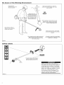
Product
Description
E4-$3000
TRIMMER
Using the accompanying illustrations
as
a guide, familiarize yourself with this unit
and its various components.
See Figure 4.
Understanding
your unit helps ensure top
performance,
long service life, and safer
operation.
Throttle Interlock
Ignition Switch
Handle
Fuel
Tank
Outer Tube
Gear
WARN|NG!
Throttle
Trigger
Do not make unauthorized
modifications or alterations to any of these units
or their components,
Case
Cutting
Attachment Shield
Trimmer Head
Figure 4
Specifications
Dry weight
E4-$3000
(less attachments) .....................................
Engine model .......................................................................
lb./5.0 kg
Spark plug ..................................................................... NGK CMR5H
SF2510E
Air cleaner type ...................................... Non-reversible heavy-duty
filter element
Engine type ................................................... Power Boost Chamber
Bore x stroke ............................................... 1.3 x 1.1 in./34 x27 mm
Displacement ........................................................
1.5 cu. in./24.5 cc
Maximum power ........................................................ 1.1 HP/0.8 kW
@ 7500 rpm (mill -1)
Fuel/oil ratio ............................... 50:1 with ISO-L-EGD or JASO FC
class 2-cycle mixing oil*
Carburetor
type ................................. Walbro WYL, diaphragm-type
Fuel tank capacity ..................................................... 20.3 oz./600 ml
Starting method ........................................................................
Recoil
Stopping method ............................................................. Slide switch
Transmission
EPA Emission
type .............................. Automatic, centrifugal clutch
w/bevel gear
Compliance Period** ............................ Category A
** The EPA emission compliance referred to on the emission compliance
label located on the engine, indicates the number of operating hours for
which the engine has been shown to meet Federal emission requirements.
Category C = 50 hours (Moderate),
B = 125 hours (Intermediate)
and A = 300
hours (Extended).
Ignition ............................................................. One-piece electronic,
program-controlled
Specifications
are subject to change
Swisher E4 engine oil meets or exceeds these specifications
and is recommended for all Swisher products.
without notice.
This unit comes fully assembled with the
exception of the cutting attachment shield
and cutting attachment.
Prior to Assembly
Before assembling, make sure you have all
the components required for a complete
unit and inspect unit and components for
any damage.
m Engine and shaft assembly
m Cutting attachment
m Kit containing
cutting attachment shield
mounting bracket and hardware, this
owner's/operator's
manual and tool kit
for routine maintenance. Tool kits vary
by model and may include a hex wrench
set, a spark plug/screwdriver
combination wrench, and a spanner.
The terms "left", "left-hand", and "LH";
"right", "right-hand", and "RH"; "front" and
"rear" refer to directions as viewed by the
operator during normal operation,
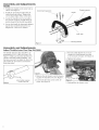
Assemb|y
and Adjustments
Handle
1. Position the handle on the outer tube as
shown. See Figure 3.
Socket-head
Throttle Assembly
Capscrews
Handle
2. Install the mounting bracket with the
socket head cap screws. Tighten the
screws finger-tight ONLY at this time.
3. Ix)care the handle in the best position
for operator comfort (usually about 10
inches ahead of the throttle assembly).
4. Secure the handle by alternately tightening the four socket-head screws in a
diagonal or "criss-cross" fashion.
""
Outer Tube
ij
q
_
Figure
Assembly
Adjust
Throttle
Mounting
Bracket
3
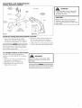
and Adjustments
Lever Free Play E4-$3000
3. Turn the cable adjuster in or out as
required to obtain proper free play
3/161/4 inch (4-6 mm). See Figure 8.
The throttle lever free play should be approximately
3/161/4
inch (4-6 mm). See
Figure 6. Make sure that the throttle lever
operates smoothly without binding.
If it
becomes
necessary to adjust the lever free
play, follow the procedures
and illustrations that follow.
4. Tighten the locknut.
Figure
7
1. Remove the air cleaner cover by loosening the two thumbscrews. See Figure 7.
3/16-1/4 inch (4-6 mm)
Throttle Free Play
Figure
6
2. Loosen the lock nut on the cable adjuster. See Figure 8.
Figure
8
5. Reinstall the air cleaner cover.
Assembly
Cutting
and Adjustments
Attachment
Shield
Head Cap __
Screw
E4-$3000
WARN|NG!
Outer
Tube
Cutting
Attachment
Shield
NEVER operate the unit without the
cutting attachment shield installed
and tightly secured!
Bracket __-_-i
CAUT|ON!
Shim __
Nuts
Line Cutter
I
Retaining
Nut
Shim
Cutting
Attachment
Mounting Plate
Scre ws
Figure
Figure
9
9A
Install the Cutting Attachment
Shield E4-$3000
2. Fit the two shims and the bracket over
1. Insert the cutting attachment shield
the outer tube and loosely install the
between the outer tube and the cutting
four socket-head screws. See Figure 9.
attachment mounting plate. See Figure 9.
3. Tighten the four socket-head cap screws
to secure the cutting attachment shield.
It may be necessary to loosen the retaining
nut and clamp screw to adjust cutting attachment shield mounting plate.
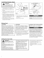
To Change
Position
of Line
Cutter,
The line cutter can be positioned in 2
positions to obtain different line length for
cutting.
1. Remove the 2 hex screws with a 4mm
hex wrench. See Figure 9A.
2. Rotate line cutter. See Figure 9A.
3. Reinstall the two hex screws and
tighten them securely.
_IL
WARN|NG!
The line cutter is very sharp. Wear
gloves to protect your hands when
handling.
Be careful to not lose the 2 nuts in the cutting
attachment shield, they are not captured.
Make sure the clamp screw and retaining nut are securely tightened
before tightening the four socket-head
cap screws.
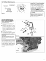
Install
the
Trimmer
Head
Turn trimmer head
COUNTERCLOCKWISE
to tighten
_
WARNING!
A standard grass trimmer
machine should NEVER be operated with blade-type attachments.
Tool holder
Position
attachment
so that the
gearcase
output shaft
faces UP
1. Turn the trimmer over so that the gearcase
output shaft faces UR See Figure 5.
2. Remove and discard
ing plug.
3.
the plastic retain-
Output shaft
Position the tool holder as shown, and
slide the holder onto the output shaft.
See Figure 5.
4. Rotate the tool holder and shaft until the
notch in the holder aligns with the notch
on the gearcase flange, and use the long
end of the hex wrench to lock the output
shaft in position. See Figure 6.
5. While holding the hex wrench, thread
the trimmer head onto the output shaft,
turning counter-clockwise.
Mixing
Never use any type of gasoline containing more than 10% alcohol by volume! Some types of gasoline contain
alcohol as an oxygenate. Oxygenated
gasoline may cause increased operating temperatures.
Under certain conditions, alcohol-based
gasoline may
also reduce the lubricating qualities of
some 2-cycle mixing oils. Generic oils
and some outboard oils may not be
intended for use in high-performance
engines, and should never be used in
your Swisher engine.
,_
Figure
$
6. Using hand pressure
trimmer head firmly
See Figure 6.
7. Remove
only, tighten the
on the gearshadt.
the hex wrench.
6
The trimmer head has a left-hand thread.
Turn the trimmer head counter-clockwise
m install.
Fuel
CAUTION[
Filling
/igure
the
Fuel
CAUTION[
Examples
This engine is designed to operate on
a 50:1 mixture consisting of unleaded
gasoline and ISO-L-EGD or JASO FC
class 2-cycle mixing oil only. Use of
non-approved
mixing oils can lead to
excessive carbon deposits.
m 1 gallon of gasoline to 2.6 oz. mixing oil
m Use only fresh, clean unleaded gasoline
with a pump octane of 87 or higher.
m Mix all fuel with a 2-cycle aipcooled mixing oil that meets or exceeds ISO-L-EGD
and/or JASO FC classified oils at 50:1
gasoline/oil ratio.
of 50:1 mixing
quantities
m 5 liters of gasoline to 100 ml. mixing oil
Mix only enough fuel for your immediate
needs! If fuel must be stored longer than 30
days and Swisher E4 Engine Oil with fuel
stabilizer is not used, it should first be treated
with a fuel stabilizer such as STA-BIL TM.
Swisher E4 Engine Oil is a registered JASO
FC classified oil and also meets or exceeds
ISO-L-EGD performance
requirements.
Swisher E4 engine oil is recommended
for
use in all Swisher low emissions engines and
also includes a fuel stabilizer.
Tank
WARNING!
Minimize the Risk of Fire
NEVER smoke or light fires near the
engine.
ALWAYS stop the engine and allow
it to cool before refueling. Avoid overfilling and wipe off any fuel that may
have spilled.
ALWAYS inspect the unit for fuel
leaks before each use. During each
refill, check that no fuel leaks from
around the fuel cap and/or fuel tank.
If fuel leaks are evident, stop using the
unit immediately. Fuel leaks must be
repaired before using the unit.
ALWAYS move the unit at least 10
feet (3 meters) away from a fuel storage area or other readily flammable
materials before starting the engine.
NEVER place flammable material
close to the engine muffler.
NEVER operate the engine without
the muffler and spark arrester screen
in place.
1. Place the trimmer
on a fiat, level surface.
2. Clear any dirt or other debris from
around the fuel filler cap.
3. Remove the fuel cap, and fill the tank
with clean, fresh fuel.
4. Reinstall
firmly.
the fuel filler cap and tighten
Starting
the
Engine
,_
WARNING!
The cutting attachment may
rotate when the engine is started!
_
WARNING!
Never start the engine without the tool assembly and cutting
attachments installed to the engine.
Failure to do so could damage the
engine and increase unexpected risk
to the operator and any bystander.
_h_
ARN|NG!
Never start the engine from
the operating position.
Engine ignition is controlled by a two position switch mounted on the throttle housing labeled, "1" for ON or START and "O" for OFF or STOP.
Slide the ignition switch to the "ON" position. See Figure 6.
Set the choke lever to the "CLOSED" position if engine is cold.
Ignition Switch
When the engine starts, slowly move the
choke lever to the "OPEN" position. See
Figure 10. (If the engine stops aster the
initial start, close the choke and restart.)
ON
Button
Throttle
Trigger
Figure 6
Set the throttle
lever to the "fast idle";
Squeeze the throttle lever toward the
hand grip on the shast tube.
Depress
ton.
and hold the throttle
lock but-
While depressing the throttle lock button,
release the throttle lever. See Figure 6.
Figure
8
While holding the outer tube firmly with
your left hand, use your other hand to
slowly pull the recoil starter handle until
resistance is felt, then pull quickly to
start the engine.
Press the primer bulb until fuel can be seen
flowing in the transparent return tube.
Make sure the cutting
attachment is clear of
obstructions!
Figure
10
If the engine fails to start after several attempts with the choke in the closed position, the engine may be flooded with fuel.
If flooding is suspected, move the choke
lever to open position and repeatedly pull
the recoil starter to remove the excess
fuel and start the engine. If the engine still
fails to start, See the section "Starting a
Flooded Engine" for instructions.
Return Tube__
When
the
Engine
Starts...
[] After the engine starts, allow the
•
tll"
*
The primer system only pushes fuel
through the carburetor. Repeatedly
pressing the primer bulb will not flood the
engine with fuel.
Figure
9
CAUTION!
Do not pull the recoil starter to the
end of the rope travel. Pulling the
recoil starter to the end of the rope
travel can damage the starter.
engine to warm up at idle 2 or 3 minutes before operating the unit.
[] After the engine is warm, pick up the
unit and clip on the shoulder strap.
[] Advancing the throttle makes the cut-
ting attachment turn faster; releasing
the throttle permits the attachment to
stop turning. If the cutting attachment
continues to rotate when the engine
returns to idle, carburetor idle speed
should be adjusted (see "Adjusting
Engine Idle").
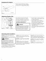
Stopping
the
Engine
Idle the engine briefly before stopping
(about 2 minutes), then slide the ignition
switch to the "O" (Engine OFF) position.
OFF
E4-$3000
ure 21
Adjusting
Engine
|die
The engine must return to idle speed
whenever the throttle lever is released.
Idle speed is adjustable, and must be set
low enough to permit the engine clutch to
disengage the cutting attachment.
__lJ
|die
Speed
Adjustment
WARNING!
Figure
22
The cutting attachment must NEVER
rotate at engine idle! If the idle speed
cannot be adjusted by the procedure
described here, return the trimmer to
your Swisher dealer for inspection,
Idle
Checking
Unit
Condition
NEVER operate the unit with the cutting attachment shield or other protective
devices removed!
A cutting attachment shield or other
protective device is no guarantee
of protection against ricochet. YOU
MUST ALWAYS GUARD AGAINST
FLYING DEBRIS!
Use only authorized
Swisher parts and
accessories
with your Swisher trimmer. Do
not make modifications
to this unit without
10
approval
from Swisher,
ALWAYS make sure the cutting attachment is properly installed and firmly tightened before operation.
NEVER use a cracked or warped cutting
attachment: replace it with a serviceable
WARN|NG!
written
1. Place the trimmer on the ground, then
start the engine, and then allow it to idle
2-3 minutes until warm.
2. If the attachment rotates when the
engine is at idle, reduce the idle speed
by turning the idle adjustment screw
counter-clockwise. See Figure 22.
3. If a tachometer is available, the engine idle
speed should be final adjusted to 3,000
(_+300)RPM (min-1).
4. Carburetor fuel mixture adjustments are
preset at factory and cannot be serviced
in the field.
Inc.
one.
ALWAYS make sure the cutting attachment fits properly into the appropriate
attachment holder. If a properly installed attachment vibrates, replace the attachment
with new one and re-check.
ALWAYS stop the engine immediately and
check for damage if you strike a foreign
object or if the unit becomes tangled. Do not
operate with broken or damaged equipment.
NEVER allow the engine to run at high
RPM without a load. Doing so could damage the engine.
NEVER operate a unit with worn or damaged fasteners or attachment holders.
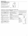
Shoulder
Operating
Strap
With
A Trimmer
Head
Although a shoulder strap accessory is
not required for use with a grass trimmer,
a shoulder strap can increase operator
comfort during extended periods of
operation. See Figure 23.
Adjust the shoulder strap so the
rests comfortably on the off-side
the cutting path of the cutting
is parallel to the ground. Make
hooks and adjustment
devices
Cutting
shoulder pad
shoulder and
attachment
sure all
are secure.
GrassmUnits
1
Figure
equipped
Your Swisher unit may be equipped with
one of several Swisher trimmer head models, each with features for specific applications and/or operational
requirements.
For proper operation, always refer to the
instructions accompanying the trimmer head
being used. Available trimmer head styles
include:
m Semi-automatic.
Trimmer line is
indexed when the operator taps the
trimmer head on the ground during
operation.
m Manual. The operator indexes line manually with the grass trimmer stopped.
m Fixed. The operator must stop the unit
and add new lengths of trimmer line
manually.
m Nail. This device, designed for clearing
weeds and light brush, features three
nylon blades attached to the head by
pivots.
Additional hardware may be required to
mount the Fixed Line or the Flail type trimmer heads.
b
23
with
a trimmer
head
CAUT|ON!
Do not push the rotating line into trees,
wire fences or any material that could
tangle or break line ends.
Engine
Operating
Speeds
Operate the unit at full throttle while cutting grass.
Hold the trimmer so the trimmer head is
angled slightly into the area to be cut. To
ensure maximum trimmer-line service life,
cut only with the tip of the trimmer line.
Cut grass by swinging the trimmer from
left to right. Keep the trimmer head horizontal. See Figure 24.
CAUTION!
Operation of trimmer without a cutting
attachment shield and using excessive
line length can lead to premature clutch
failure.
Figure
24
CAUTION!
Operation at low RPM can lead to premature clutch failure.
Edging
Tilt the handle
about 100° to the
left (from horizontal) and move
forward, holding
the trimmer vertically as shown in
Figure 25.
Figure
25
11
General
Maintenance
MAINTENANCE, REPLACEMENT OR
RE-PAIR OF EMISSION CONTROL
DEVICES AND SYSTEMS MAY BE PERFORMED BYANY REPAIR ESTABLISHMENT OR INDIVIDUAL; HOWEVER,
WARRANTY REPAIRS MUST BE PERFORMED BYA DEALER OR SERVICE
CENTER AUTHORIZED BY SWISHER.
THE USE OF PARTS THATARE NOT
EQUIVALENT IN PERFORMANCE AND
DURABILITY TO AUTHORIZED PARTS
MAY IMPAIR THE EFFECTIVENESS OF
THE EMISSION CONTROL SYSTEM
AND MAY HAVE A BEARING ON THE
OUTCOME OF A WARRANTY CLAIM.
_IkWARN|
NG!
Before performing any maintenance,
repair or cleaning work on the unit,
make sure the engine and cutting attachment are completely stopped. Disconnect the spark plug wire before performing service or maintenance work.
Using non-standard replacement parts could
invalidate your Swisher warranty.
Muffler
This unit must never be operated with a faulty
or missing spark arrester or muffler. Make
sure the muffler is well secured and in good
condition. A worn or damaged muffler is a
fire hazard and may also cause hearing loss.
Spark
WARNING!
Non-standard parts may not operate
properly with your unit and may cause
damage and lead to personal injury.
Plug
Keep the spark plug and wire connections
tight and clean.
Fasteners
Make sure nuts, bolts, and screws (except
carburetor adjusting screws) are tight.
Air Filter
The E4 engine that powers your Swisher model is a hybrid 4-stroke engine. As a hybrid,
the engine is lubricated by oil mixed with
the gasoline and air from the carburetor that
moves through and around the internal parts
Daily
of the engine in a similar way that a 2-stroke
engine is lubricated. Without the heavy duty
2-stage air filter equipped on all E4 engines,
dust and dirt could also move through the engine, decreasing engine life, increasing valve
wear and the need for more frequent valve adjustments. To keep your E4 engine strong and
reliable, Swisher recommends that you check
and service the air filter as instructed in the
10-Hour Maintenance section that follows.
Maintenance
Prior to each work day, perform
following:
the
m Remove dirt or debris from the engine,
check the cooling fins and air cleaner for
clogging and clean them as necessary.
I 0-Hour
m Carefully remove any accumulation of
dirt or debris from the muffler or the
fuel tank. Dirt build-up in these areas
could cause engine overheating, induce
premature weal', or create a fire hazard.
m Check for loose or missing screws or
components. Make sure the cutting attachment is securely fastened.
m Check the entire unit for leaking fuel or
grease.
Maintenance
(more frequently in dusty conditions)
1. Remove the air cleaner cover by loosening
the two thumbscrews. See Figure 28A.
Unscrew
Fasteners
Pre-Filter
2. Remove and inspect the pre-filter. If the
pre-filter is torn or otherwise damaged,
replace it with a new one. See Figure 28B.
3. Clean the pre-filter with soap and water.
Let dry before reinstalling.
Air Cleaner
Element
4. Inspect the air cleaner element. If the
element is damaged or distorted, replace
it with a new one.
5. Tap filter gently on a hard surface to dislodge debris from element or use compressed air from the inside to blow debris
out and away from the air cleaner element.
Direct the air stream at the inside face of
the filter only!
12
Figure
28,4
6. Install the air cleaner element, pre-filter
and cover in the reverse order of removal.
Figure
28B
CAUTION!
Never operate the unit if the air cleaner
assembly is damaged or missing!
10/15-Hour
Maintenance
Every
0.024-0.028
inch
(0.6-0. 7 mm)
10 to 15 hours
of operation:
Remove and clean the spark plug. Adjust
the spark plug electrode gap to 0.024 - 0.028
inch (0.6 - 0.7 ram). If the spark plug must
be replaced, use only an NGK CMR5H or
equivalent resistor type spark plug of the
correct heat range. See Figure 29.
Clean the spark plug
and check the gap at
the electrode.
The NGK CMR5H also meets the requirements for electro magnetic compliance (EMC).
CAUTION!
Figure
29
50-hour
Before removing the spark plug, clean
the area around the plug to prevent
dirt and debris from getting into the
engine's internal parts,
Maintenance
Every 50 hours of operation
(more frequently
in dusty or
dirty conditions):
II Remove and clean the cylinder cover
and clean grass and dirt from the
cylinder fins.
II Remove the cutting attachment, cutting
attachment holder and gear shaft collal:
Remove the filler plug from the side of
the gear case and press new grease into
the gear case until old grease is pushed
out. Use only lithium-base grease. See
Figure 30.
II Lubricate main shaft splines.
II Use a hooked wire to extract the fuel filter
from inside the fuel tank. See Figure 31.
New
Grease
Old
Grease
Gear
Shaft
Remove and replace the filter element.
CAUT|ON!
Figure
30
Collar
C_
Make sure you do not pierce the fuel
line with the end of the hooked wire.
The line is delicate and can be damaged easily.
Before reinstalling the new filter element,
inspect the condition of all the fuel system
components (fuel pick-up line, fuel return
line, tank vent line, tank vent, fuel cap and
fuel tank). If damage, splitting or deterioration is noted, the unit should be removed
from service until it can be inspected or
repaired by a Swisher-trained service
technician.
13
139/150-Hour
Maintenance
Maintenance
after first 139-hours,
then every
Combustion chamber should be decarbonized, and the valve clearance should
be adjusted. It is highly recommended
that this is done by a Swisher-trained
service technician.
Valve
150-hours
thereafter.
The NGK CMRSHalso meets the requirements
for electro magnetic compliance _MC).
m Replace the spark plug annually: Use
only NGK CMR5H or equivalent resistor type spark plug of the correct heat
range. Set spark plug electrode gap to
0.024-0.028 inch (0.6 -0.7 mm).
Adjustment
1. Remove cylinder cover, rocker arm cover,
and spark plug. Rotate the crankshaft
while observing the piston through the
spark plug opening. When the piston
is at the top of the compression stroke
(TDC), the valves can be adjusted.
CAUT|ON!
II Performing a valve adjustment
incorrectly may cause hard starting
and/or can damage the engine.
2. Ix)osen adjuster locknut so that the 2.5
mm Allen socket head adjustment screw
can turn freely.
II If you are unfamiliar with this engine
or uncomfortable with this procedure, consult with an authorized
Swisher servicing dealer.
3. Insert 0.10 mm (0.004") feeler gauge
between valve stem tip and rocker arm.
4. Turn adjustment screw (clockwise =
tighter, counter-clockwise = looser) until
feeler gauge is almost snug. Back off
just enough to allow gauge to slip out
with limited resistance.
5.
Spark
Attester
Screen
6. Turn engine over several times, and returnthe to TDC-compression. Recheck
with proper feeler gauge to make sure
clearance adjustment did not change
as a result of tightening the locknut.
Readjust as necessary.
7. Replace rocker arm cover gasket to assure proper sealing and install cover.
If a new gasket is not available and/or the
old gasket is not damaged, the old gasket
may be reused. Never use cracked or
damaged gaskets!
While holding the adjustment screw in
place with the Allen driver, tighten the
locknut with a wrench.
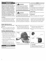
Maintenance
If the engine becomes sluggish and low on power, check and clean the spark arrester screen.
Engine
Cover_
Scre ws
i
I
WARN|NG!
If you note excessive carbon buildup, consult
with an authorized E4 Swisher servicing
dealer. Contact Swisher Inc. at (800) 222-8183,
or go to www.swisherinc.com for assistance.
Neveroperate the unitwith a damaged
or missing muffleror spark arrester!
Operatingwith a missing or damaged
spark arrester is a fire hazard and
could also damage your hearing.
These instructions
refer to Figure
32.
I
i
I
I
1. With a 3 rrnn hex wrench remove the 3
engine cover screws and the engine cover.
2. With a 4 mm hex wrench remove the 3
muffler bolts and the muffler.
3. With a small flat bladed screwdriver
remove the 2 screws holding the spark
arrester screen and cover to the muffler.
4. Remove the screen
stiff bristle brush.
/
Muffler
Bolts
.........
_a /
5. Inspect the cylinder exhaust port for any
carbon buildup.
14
Muffler
Gasket
_2
and clean it with a
6. Reassemble the spark arrester, muffler
and engine cover in the reverse order of
disassembly.
Muffler
Screen
Figure
32
Spark Arrester
Cover
Cover
Screws
Long
Term
Storage
Whenever
the unit will not be used for 30
days or longer, use the following procedures to prepare it for storage:
II Clean external
parts thoroughly.
II Drain all the fuel from the fuel tank.
All stored fuels should be stabilized with
a fuel stabilizer such as STA-BIL TM, if
Swisher E4 Engine Oil with fuel stabilizer
is not used.
CAUT|ON!
Gasoline
stored in the carburetor
for
extended periods can cause hard starting and could also lead to increased
service and maintenance cost.
Remove the remaining
lines and carburetor.
fuel from the fuel
1. Prime the primer bulb until no more fuel
is passing through.
2. Start and run the engine until it stops
running.
3. Repeat steps 1 and 2 until the engine will
no longer start.
II Remove the spark plug and pour about
1/4 ounce of 2-cycle mixing oil into the
cylinder through the spark plug hole.
Slowly pull the recoil starter 2 or 3 times
so oil will evenly coat the interior of the
engine. Reinstall the spark plug.
II Before storing the unit, repair
any worn or damaged parts.
or replace
II Remove the air cleaner element from the
carburetor
and clean it thoroughly with
soap and water. Let dry and reassemble
the element.
m Store the unit in a clean, dust-free
area.
Speed-Feeff 375 LoadingInstructions PIN78890-28000
I0
Align
Alinear
\
5
4
1
TM
Aligner
Allineare
Austrichten \
_@_2
5"(127cm)
4
No.
Part Number
Part Name
Descripcien
Nora de la piece
Denominazione
Beschreibung
Qty.
1
78890-11330
SPOOLLH
CARRETELH
BOBINE LH
BOBINALH
SPULELH
1
2
78890-11380
BUSHING
BUJE
BAGU E
BOCCOLA
REDUZIERRING
1
3
78890-11310
KNOB
PERILLA
POIGNEE
MANOPOLA
DREHSCHEIBE
1
4
28820-07350
CORE
BASECENTRAL
MOYEU
5
78890-11320
EYELETCARRIER
6
28820-07340
EYELET
BOQUILLAS
7
28820-07380
CAP
TAPA
8
17500-23600
SPRING
9
28820-09310
COVER
10
78890-25310
STUD,7 MM LH
PARTEINTERNA
KERNSTOCK
1
SUPPORTODELL'OCCHIELLO
FENSTERELEMENT
1
PASSE-CABLE
OCCHIELLO
FENSTER
2
CAPUCHON
CAPPELLO
VERSCHLUSSAUFBAU
1
RESORTE
RESSORT
GRUPPOMOLLA
FEDER
1
TAPA
COUVERCLE
COPERCHIO
DECKEL
1
PERNO,7 MM LH
BOULON, 7 MM LH
BULLONE,7 MM
SCHRAUBBOLZEN,
7 MM
1
SOPORTEDE BOQUILLAS CORP DE POULIE
15
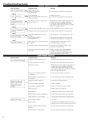
Troub|eshootin
Guide
What To Check
Does the engine crank?
_
Possible Cause
Remedy
Flnkt in the crankcase.
aulty recoil starter.
Internal damage.
Consult with an authorized
servicing dealer.
Consult with
an authorized
Tighten
and re-test.
servicing dealer.
YES 1
Good compression?
I NO
I Ix)ose spark plug.
Excess wear on cylinder, piston, rings.
Valves not seating.
/
YES
I Fuelincorrect,
NO
Does the tank contain
fresh fuel of the proper
grade?
V_
Refill with flesh, clean unleaded gasoline with
a pump octane of 87 or higher mixed with
a 2-cycle air cooled nlixing oil that meets or
exceeds ISO-L-EGD and/or JASO FC classified
oils at 5(}:1gasoline/oil ratio.
stale or contaminated;
mixture incorrect.
YES Jr
Is fuel visible and moving
[NO J Check for clogged fuel filter and/or
in the return line when
priming?
_
vent.
Priming pump not flmctioning properly.
Replace fl_el filter or vent as required;
Consult with an authorized
restart.
servicing dealer.
YES
Is there spark at the spark INO
plug wire terminal?
I
[
YES J_
IThe ignition switch is in "O" {OFF)
position.
I Shorted ignition ground.
Faulty ignition unit.
Check the spark plug.
If the plug is wet, excess fuel may be in
the cylinder.
What To Check
Is tile engine overheating?
_
I
,
Replace the plug with an NGK CMR5H or
equivalent resistor type spark plug of the
correct heat range. Set spark plug electrode
gall to (/.024-(/.028 inch (0.6-(/.7 ram).
Operator
mixture
16
the unit.
is too lean.
fuel ratio.
Shorten
trimmer line. Cut at a slower rate.
Consult with an authorized
servicing
dealer.
Refill with flesh, clean unleaded gasoline with
a pump octane of 87 or higher mixed with
a 2-cycle air cooled mLxing oil that meets or
exceeds ISO-L-EGD and/or JASO FC classified
oils at 50:1 gasoline/oil ratio.
Fan, fan cover, cylinder fins dirty
or damaged.
Clean, repair or replace as necessary.
Carbon deposits on the piston or in
the muffler.
Consult with an authorized
Clogged air cleaner element.
Service
the air cleaner
Loose or damaged
Tighten
or replace.
spark plug.
servicing
dealer.
element.
Air leakage or clogged fuel line.
Repair
Water in the fuel.
Replace
the fuel.
Piston seizure.
Consult
with
an authorized
servicing
dealer.
Consult
with
an authorized
servicing
dealer.
Consult
with
an authorized
servicing
dealer.
Valve clearance
]_
Remedy
is overworking
Faulty carburetor
Engine is knocking.
Crank the engine with the plug removed,
reinstall the plug, and restart.
Tile plug is damaged internally or of the
wrong size.
Improper
/
servicing dealer.
servicing dealer.
Clean and regap the plug to 0.024 -0.028
inch (0.6 - (1.7ram). Restart.
Carburetor
Engine is rough at all
speeds. May also have
black smoke and/or
unburned fuel at the
exhaust.
Consult with an authorized
Consult with an authorized
Tile plug is fouled or improperly gapped.
Possible Cause
[
Move switch to 'T' (ON) position and restart.
and/or
diaphragm.
set incorrectly.
or replace
filter
and/or
See page
fuel line.
10.
Overheating condition.
See above.
Improper fuel.
Check fuel octane rating; check for presence of
alcohol in the fuel (pg. 10). Refuel as necessary.
Carbon deposits in the combustion
chamber.
Consult with an authorized servicing dealer.
Valve clearance
Consult with an authorized
set incorrectly.
servicing
dealer.
Troubleshooting
Guide
(continued)
Possible Cause
Symptom
Clogged
air filter,
Remedy
Clean tile air filter.
Clogged
fuel filter,
Replace tile fuel filter.
Poor acceleration.
Lean fuel/air
Idle speed
mixture.
set too low.
Switch turned
off.
Consult with an authorized servicing dealer.
Adjust: 3,000 (±300) RPM (mind).
Reset tile switch and restart.
Engine stops abruptly.
[Engine
difficult to shut off._
Fuel tank empty,
Refuel. See page 10.
Clogged
Replace fuel filter.
fuel filter,
Water in the fuel,
[)rain; replace with clean fuel. See page 10.
Shorted
Clean and replace spark plug, tighten
tile terminal.
spark plug or loose terminal,
Ignition failure.
Replace tile ignition unit.
Piston seizure.
Consult with an authorized servicing dealer.
Ground (stop) wire is disconnected or
switch is defective.
Test and replace as required.
Overheating due to incorrect spark plug.
Idle engine until cool.
Clean and regap tile plug to 0.024- 0.028
inch (0.6- 0.7 ram). Correct plug: NGK CMR5H
or equivalent resistor type spark plug of tile
correct
Overheated engine.
range.
Idle engine until cool.
Consult with an authorized servicing dealer.
Top ofand
dirty
engine
oily. is getting
_
Valve cover is leaking.
Set idle: 3,000 (±300) RPM (rain-l).
Cutting attachment
rotates at engine idle.
_
Broken clutch spring or worn clutch
spring boss.
Engine idle too high.
Loose attachment holder.
Replace spring/shoes as required, check
idle speed.
Inspect and re-tighten holders securely.
Set idle: 3,000 (±300) RPM (rain-l).
[ Engine will not idle down. ]-----,,+ Engine idle set t°° higlL
Engine has an air leak.
Symptom
I Excessive vibration.
Possible Cause
Consult with an authorized servicing dealer.
Warped or damaged cutting attachment.
Remedy
Inspect and replace attachment as required.
Loose gearcase.
Tighten gearcase securely.
Bent main shaft/worn or damaged
bushings.
Inspect and replace as necessary.
Trhnmer line not wound properly on spool. Rewind trhnmer line.
Cutting attachment will
not rotate.
Shaft not installed in powerhead or
gearcase.
Broken shaft.
Damaged gearcase.
17
NOTES
18
NOTES
19
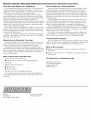
Emission
System
Your Warranty
Rights
Warranty
and
Statement
(Administered by Shindaiwa Corporation)
Obligations
The California Air Resources Board, the U.S. Environmental
Protection Agency and Shindaiwa Corporation are pleased to
explain the exhaust and evaporative emission control system warranty on your new small off-road (non-road) engine.
In California, new small off-road engines must be designed,
built, and equipped to meet the State's stringent anti-smog standards. In other states, new 1997 and later non-road engines must
meet the Federal EPA's stringent anti-smog standards.
Shindaiwa Corporation must warrant the emission control system
on your small off-road engine for the periods of time listed below,
provided there has been no abuse, neglect, or improper maintenance of your small off-road engine.
Your engine exhaust and evaporative emission control system
includes parts such as the carburetol; fuel tank, the ignition system and, if equipped, the catalytic converter. These components
are specifically listed below.
Where a warrantable condition exists, Shindaiwa Corporation
will repair your small off-road engine at no cost to you including
diagnosis, parts, and labol:
Owners
Warranty
As the small off-road engine owner, you are responsible for the
performance of the required maintenance listed in this owners
manual. Shindaiwa Corporation recommends that you retain all
receipts covering maintenance on your small off-road engine, but
Shindaiwa Corporation cannot deny warranty solely for the lack of
receipts or for your failure to ensure the performance of all scheduled maintenance.
As the small off-road engine owner, you should be aware, however, that Shindaiwa Corporation may deny you warranty coverage if your small off-road engine or a part has failed due to abuse,
neglect, improper maintenance, or unapproved modifications.
You are responsible for presenting your small off-road engine to
an authorized Shindaiwa Corporation Dealer as soon as a problem
exists. The warranty repairs should be completed in a reasonable
amount of time, not to exceed 30 days.
If you have any questions regarding your warranty rights and
responsibilities, you should contact a Shindaiwa Corporation customer service representative or your local Shindaiwa Dealer.
Consequential
Manufacturer's
Warranty
Coverage
When sold within the U.S., this engine's emission control system is warranted %r a period of two (2) years from the date this
product is first delivered to the original retail purchaser.
During the warranty period, Shindaiwa Corporation will, at
their option, repair or replace any defective emission-related component on this engine. During the original Warranty Period, these
Warranty Rights are automatically transferable to subsequent
owners of this product.
What
is Covered
1. Carburetor
Damages
In the event that other component parts of this product are damaged by the failure of a warranted part, Shindaiwa Corporation will
repair or replace such component parts at no charge to you.
What
is Not Covered
Failures caused by abuse, neglect, or improper
procedures.
This Warranty
is Administered
m Throttle Valve, Needle, Jet, Metering Diaphragm
Shindaiwa Corporation
11975 SW Herman Road
Tualatin, OR 97062
(503) 692-3070
2. Fuel Tank
3. Ignition System Components
m Ignition Coil
m Flywheel Rotor
(if originally equipped)
The emission control system for your particular Shindaiwa
Corporation engine may also include certain related hoses and
connectors.
Swisher
RO. Box 67
Warrensburg,
Part Number 81950
Revision 12/2007
MO 64093
maintenance
m Failures caused by the use of modified or non-approved parts or
attachments.
by this Warranty
Internal Components
4. Catalytic Converter
Responsibilities
by',