1
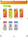
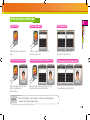
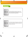
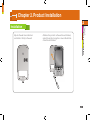
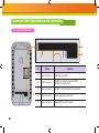
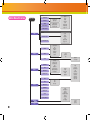
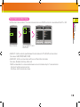
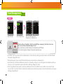
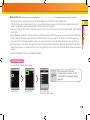
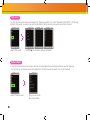
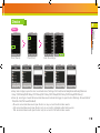
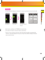
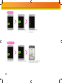
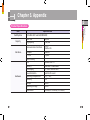
www.supremainc.com X-Station Smart IP Access Terminal User Guide 7FS Contents Product Features… ……………………………… 4 Safety Instructions………………………………… 5 Chapter 1. Before use… ………………………… 6 Package Contents… ………………………………… 6 Basic Items…………………………………………………… 7 Option… ……………………………………………………… 8 Product Part Description… ………………………… 7 Name and Function… ……………………………………… 7 Product Size… ……………………………………………… 8 Display… ……………………………………………… Standby Screen… …………………………………… Authorization Process………………………………… CSN/Data Card … …………………………………… 9 10 11 12 Chapter 2. Product Installation… …………… 13 Installation… ………………………………………… 13 Connector/Cable Specifications and Connection 14 Connector Specifications………………………………… 4 Pin Connector…………………………………………… 8 Pin Connector…………………………………………… 3 Pin Connector…………………………………………… 5 Pin Connector…………………………………………… 6 Pin Connector…………………………………………… Power Connection………………………………………… Ethernet Connection……………………………………… RS485 Connection with the PC… ……………………… 14 15 15 16 16 17 18 19 20 RS485 Connection to Secure I/O or Other Terminals Relay Connection - Fail Safe Lock… …………………… Relay Connection - Fail Secure Lock…………………… Relay Connection – Automatic Door… ………………… TTL Switch Connection…………………………………… 21 22 23 24 25 Wiegand Input … ………………………………………… 26 Wiegand Output…………………………………………… 26 System Setup… ……………………………………… 27 Independent Version……………………………………… 27 Secure Version (Secure I/O)…………………………… 27 Network Setup… ………………………………………… 28 Chapter 3. User Functions… ………………… 29 Access Authorization… ……………………………… 29 Card Authorization………………………………………… Use of Card+Face Detection… ………………………… Use of Card+Password Authorization…………………… Use of Card+Password+Face Detection Authorization Use of ID+Password Authorization……………………… Use of ID+Password+Face Detection Authorization…… 29 29 30 30 31 31 Use of T&A Authorization… ………………………… 32 T&A Authorization in Auth Mode………………………… T&A Mode… ……………………………………………… Extra T&A Events… ……………………………………… Singular Entrance /T&A Records Check… …………… 32 34 35 35 Authorization Failure… ……………………………… 36 Chapter 4. Admin Menu… …………………… 37 Registering an Admin… ………………………………… 37 Entering the Admin Menu………………………………… 39 Admin Menu Structure… ………………………………… 40 User… ………………………………………………… 41 Registering an User… …………………………………… Edit User…………………………………………………… User Search… …………………………………………… Checking the Registered User Info……………………… Deleting users……………………………………………… Registering Data Card (When Using a Data Card)… … Formatting Data Cards…………………………………… 41 43 44 45 46 48 50 Network Setup………………………………………… 51 TCP/IP Setup……………………………………………… 51 Server Setup… …………………………………………… 52 Serial Communication Setup… ………………………… 53 Task Management… ………………………………… 54 Mode… …………………………………………………… T&A Management………………………………………… T&A event… ……………………………………………… Camera Event……………………………………………… 54 55 56 56 Device… ……………………………………………… 57 Door………………………………………………………… Time Setup………………………………………………… Device Info… ……………………………………………… Memory Info… …………………………………………… Calibration… ……………………………………………… Device Reset… …………………………………………… Factory Default… ………………………………………… 57 59 60 60 61 62 62 Display & Sound… …………………………………… 63 Log Management… ………………………………… 65 Checking the Log List… ………………………………… 65 Delete All Logs… ………………………………………… 66 Check Log Info… ………………………………………… 66 Chapter 5. Appendix…………………………… 67 Product Specifications… …………………………… Electrical Specification… …………………………… FCC Rules… ………………………………………… Font License…………………………………………… 67 68 69 70 Product Features The X-Station adopts the RF card reader function to enable T&A mode and access control. 1$ The X-Station is smart IP-base device with a 3.5 inch color touchscreen LCD and provides a more intuitive User Interface. 1$ The built-in camera enables the user to store video logs and face detection technology. $"3% 1$ 1$ The X-Station can be directly connected to a PC or a server and supports Ethernet and RS485 as real-time interface. 1$ The X-Station supports a total of 16 T&A events and provides ‘ID/Card+Password’ identification mode. $"3% The X-Station is capable of storing up to 200,000 logs and 5,000 user’s pictures on the device. Furthermore, 1,000,000 normal logs, as well as 5,000 video logs can be stored. $"3% $"3% $"3% 1$ Safety Instructions The following instructions ensure your safety and prevent any property damage. Be sure to read the following instructions and use the product correctly. Do not install the terminal in a place affected by direct sunlight, humidity, dust or soot. Do not drop the terminal or subject it to heavy impact. Keep the terminal away from magnets or anything containing magnetic material such as CRT, TV sets, computer monitors and speaker. Do not apply heavy pressure to the touch screen. Keep the terminal away from heating products. Do not disassemble, repair or reconstruct the terminal. Do not spill any liquids (water, soda or solution) into the terminal. Keep the product out of reach from children. Clean the terminal regularly to prevent dust setting on it. Do not use the terminal for any other purpose than original use. Use a soft cloth or towel when cleaning the terminal. Do not uses spray water on the terminal. In cases of product malfunction or problems, please contact a service center. Chapter 1. Before use Package Contents Please check the product package contains the following items. If any of the following items is damaged or missing, please contact your retailer immediately. Basic Items Screws and holders (2 each) X-Station Terminal Bracket Cable(5) Termination resistor (2 pcs) Optional Accessories 12V Power Adapter Plastic Stand Card Reader Secure I/O Software CD Product Part Description 1 Chapter 1. Before Use Name and Function 1 2 3 4 5 No Name Function 1 Proximity Sensor Turns on LCD backlight when user gets close to sensor. 2 Camera Allows to record videos or face detection feature. 3 LCD screen Displays current status (T&A mode, notice etc.) and the time. 4 5 Function Keys FR Card sensor Uses function keys for the T&A events. Reads FR card. Product Size Product size: 79mm (W) x 135mm (H) x 21mm (D) 79mm 50.00mm 106.5mm 135mm 21mm Front View Side View Bracket Display 1 Displays Ethernet Connection status Indicates connection to PC via Ethernet Indicates slave device connection status via RS485 Clock Chapter 1. Displays door status Before Use Displays face detection mode on Displays current time Display current time and date Inputs ID for authentication Enters additional T&A events Enters the admin menu Describes F1 to F4 key When users touch the button, it operates same function as F1 to F4 key. Standby Screen 10 Logo Screen Announcement Screen Fix T&A mode Screen Terminal Locked Security mode On Data Transfer mode Auto T&A mode Screen Authorization methods Card+Face Detection Place a registered card and then, face detection authorization. Note ■ ID+Password Place a registered card, and then enter a password. Enter a registered ID, and then enter a password. Card+Password+Face Detection ID+Password+Face Detection Authorize with Card and password, and then face detection authorization. 1 Chapter 1. Authorize with a registered card. Card+Password Before Use Card Only Authorize with ID and password, and then Face detection authorization. efer to [Chapter 3. User Functions >1.Entrance Authorization] R on page 28 for further explanations. 11 CSN/Data Card $4/$BSE $4/$BSE %BUB$BSE %BUB$BSE 12 Device reads the CSN (Card Serial Number) card which is the own ID of a card. Card authentication will be allowed when the new input CSN card is matched with the registered CSN card. User information including user ID and password is saved into the card if device is set to data mode. Device reads the user information from a card when the new card is input. Chapter 2. Product Installation 2 Chapter 2. Adjusts the wall mount bracket and attach it firmly to the wall. Product Installation Installation Attaches the product on the wall mount bracket, adjust the product using the screw at the bottom of wall mount bracket. 13 Connector/Cable Specifications and Connection Connector Specifications 4 1 No 14 2 Name 5 3 Function 1 4 pin connector Ethernet connection 2 8 pin connector RS485 Port 1 (Connection with PC) / RS232 Port (Extension) 3 3 pin connector RS485 Port 2 (Slave device connection) 4 5 pin connector Power and relay connection 5 6 pin connector Wiegand I/O and TTL Switch ͤ ͨ΄ͤ͞͡ ΄ͦ͞͡ ͢ ͦ 2 4 pin connector (Ethernet Connection) ͩ ͢ ͧ ͥ Pin Pin Desctription Wire Color 1 TX + YELLOW 6 ͢ 2 TX - GREEN 3 3 RX + RED 2 4 RX - BLACK 1 ΄ͧ͞͡ RJ45 Pin Chapter 2. ͩ ͢ Product Installation ͢ ͢ 8 pin connector - RS485 port 1 (Connection with PC) / RS232 port (for extension) ͩ ΄ͩ͞͡ ͢ Pin Pin Desctription Lenngth Cable Type Wire Color 1 RS232 CTS PINK 2 RS232 RTS ORANGE 3 GND BLACK 4 RS232 TX PURPLE 5 RS232 RX 6 GND BLACK 7 RS485 TRX- YELLOW 8 RS485 TRX+ BLUE 30cm AWG26 GREEN 15 3 pin connector - RS485 port 2 (Slave device connection) Pin ͤ ͨ΄ͤ͞͡ Pin Description 1 GND ͢ 2 RS485 TRX- ͦ 3 RS485 TRX+ Pin Pin Description Length Cable Type Wire Color 30cm AWG26 YELLOW BLACK BLUE ΄ͦ͞͡ ͤ͢ ΄ͤ͞͡ 5 pin connector – Power and relayͧ ͢ ͦ ΄ͧ͞͡ ΄ͦ͞͡ ͢ ͢ ͩ ͧ ΄ͧ͞͡ ΄ͩ͞͡ ͢ 16 ͢ ͩ Length Cable Type Wire Color 1 Relay NC ORANGE 2 Relay COM BLUE 3 Relay NO 4 GND BLACK 5 12VDC RED 30cm AWG24 WHITE ͦ ͨ΄ͦ͞͡ ͢ TTL Switch 6 pin connector - Wiegand I/O and ͧ 1 2 3 4 5 6 SW IN1 SW IN0 GND Wiegand GND Wiegand D1 Wiegand D0 Length 30cm Cable Type Wire Color AWG26 ORANGE YELLOW BLACK BLACK WIHTE GREEN 2 Chapter 2. ͢ Pin Description Product Installation ͨ΄ͧ͞͡ Pin ͩ ͨ΄ͩ͞͡ ͢ 17 Power Connection (5 pin connector) X-Station (5) Power 12V (Red) DC Power supply (4) Power GND (Black) RELAY (3) Relay NO (White) (2) Relay COM (Blue) (1) Relay NC (Orange) UPS (optional) ■ Note 18 Recommended Power Specification - Voltage 12V ±10%, current 1500mA or above. You should use an authorized IEC/EN 60950-1 12V adapter. - In case of another unit providing power for X-Station, it is recommended you use an adapter for more than 1500mA. 2 Ethernet Connection (4 pin connector) Chapter 2. Product Installation HUB - After plug the 4 pin cable to the back of the terminal, connect the RJ45 socket of the 4 pin cable with a LAN cable to the hub. 19 RS485 Connection with the PC (8 pin connector) Cable shield(optional) (8) 485 TRX+ (Blue) (7) 485 TRX- (Yellow) (6) GND (Black) TRX+ TRXGND PC RS232-485 Converter X-Station Termination (8) 485 TRX+ (Blue) (7) 485 TRX- (Yellow) (6) GND (Black) X-Station Termination In case the signal is not sent correctly, you should install a terminal resistance at both ends of the bus. (120Ω resistance) ■ The signal quality can vary depending on the route, so you need to adjust the transmission speed or lower the transfer rate. ■ Note 20 2 RS485 Connection to Secure I/O or Other Terminals (3 pin connector) Chapter 2. Product Installation X-Station X-Station (3) 485 TRX+ (Blue) (2) 485 TRX- (Yellow) (1) GND (Black) (3) 485 TRX+ (Blue) (2) 485 TRX- (Yellow) (1) GND (Black) Termination Termination 4FDVSF*0 4FDVSF*0 21 Relay Connection - Fail Safe Lock (5 pin connector) X-Station (3) Normally Open / N.O (White) (2) Common (Blue) (1) Normally Close /N.C (Orange) Deadbolt / Door strike 22 DC Power supply 2 Chapter 2. Product Installation Relay Connection - Fail Secure Lock (5 pin connector) X-Station (3) Normally Open / N.O (White) (2) Common (Blue) (1) Normally Close /N.C (Orange) Deadbolt / Door strike DC Power supply 23 Relay Connection – Automatic Door (5 pin connector) RTE Switch Presence Detector Door Controller Automatic Door 24 X-Station (3) Normally Open / N.O (White) (2) Common (Blue) (1) Normally Close /N.C (Orange) 2 Chapter 2. Product Installation TTL Switch Connection(6 pin connector) X-Station SWITCH INPUT1 (3) GND (Black) (2) Switch Input 1 (Yellow) (1) Switch Input 2 (Orange) SWITCH INPUT2 25 Wiegand Input (6 pin connector) Card Reader Cable Shield (optional) X-Station (6) Wiegand DATA 0 (Green) (5) Wiegand DATA 1 (White) (4) Wiegand GND (Black) Wiegand Output. Data 0 Wiegand Output. Data 1 GND Wiegand Output (6 pin connector) Access Controller Cable Shield (optional) Wiegand Input. Data 0 Wiegand Input. Data 1 GND Note 26 ■ You can configure the Wiegand Input and Output settings in the BioStar. X-Station (6) Wiegand DATA 0 (Green) (5) Wiegand DATA 1 (White) (4) Wiegand GND (Black) System Setup 2 Chapter 2. Product Installation Secure Version (Secure I/O) Independent Version 34 %PPS 4FOTPS %PPS -PDL 94UBUJPO -"/ 1$ %PPS 4FOTPS &YJU #VUUPO %PPS -PDL 94UBUJPO &YJU 4FDVSF *0 #VUUPO -"/ 1$ 27 Network Setup 34 34 4FDVSF*0 94UBUJPO )PTU 94UBUJPO 4MBWF 94UBUJPO )PTU -"/ 1$ 1$4FSWFS 1$ 94UBUJPO )PTU 4FDVSF*0 94UBUJPO &YJU#VUUPO 1$$MJFOU 1$ 1$$MJFOU 34 28 Chapter 3. User Functions 3 Chapter 3. User Functions Access Authorization Card Authorization Card authorization is only operated in ‘Card Only’ authentication mode or registered ‘Bypass’ card. Note Place the card to the terminal. Authorization success screen will pop up on the screen. ■ The default screen will appear when authorization success. - If a user image is registered: The registered user image will be shown on screen. - If no user image is registered: The recorded image will be shown. Should the video log not be recording, the default image will be displayed on the authorization screen. Use of Card+Face Detection Face Detection is only operated when Face Detection mode is in ‘Use’. ■Face Detection Method When the face detection Note mode is on, please fit your face in the frame. Place the card to the terminal. Keep your face in front of device when the Face Detection mode is on. Authorization success screen will pop up on the screen. 29 Use of Card+Password Authorization To use password authorization, use Auth Mode with the ‘ID/Card+Password’ setup. Place the card to the terminal. Enter the password and press [OK]. Authorization success screen will pop up on the screen. Use of Card+Password+Face Detection Authorization Place the card to the terminal. 30 Enter the password and press [OK]. Capture your face image when the Face Detection screen appears. Authorization success screen will pop up on the screen. Use of ID+Password Authorization 3 To use password authorization, use Auth Mode with the ‘ID/Card+Password’ setup. Chapter 3. Enter your ID on the ID screen and then press [OK]. Enter your password and then press [OK]. User Functions Press [Input ID] on the main screen. Authorization success screen will pop up on the screen. Use of ID+Password+Face Detection Authorization Press [Input ID] on the main screen. Enter your ID on the ID screen and then press [OK]. Enter your password and then press [OK]. Capture your face image when the Face Detection screen appears. Authorization success screen will pop up on the screen. 31 Use of T&A Authorization T&A Authorization in Auth Mode Authorization only by card Press F1 to F4 for T&A events. Note 32 ■ You Place the card to the terminal when the Card/ID input screen appears. can use Face Detection mode with T&A mode. When the Face Detection mode is activated, you have to successfully authorize card and face to enter. Authorization success screen will pop up on the screen. At the same time the T&A event is applied. ID/Card+Password Authorization 3 Chapter 3. Place the card to the terminal. Enter your password and then press [OK]. Authorization success screen will pop up on the screen. At the same time the T&A event is applied. ID+Password Authorization Press F1 to F4 for each of the T&A events. Press [Input ID]. Enter your ID on the ID screen and then press [OK]. Enter your password and then press [OK]. Authorization success screen will pop up on the screen. At the same time the T&A event is applied. 33 User Functions Press F1 to F4 for each of the T&A events. T&A Mode If you set up the T&A mode to [Manual], users must press the F1 to F4 key every time you enter or leave to record T&A events. If you set up the T&A mode to [Auto], users do not have to select a T&A event. The device will automatically change T&A events to correspond with the functions specified for a time period. Users can select different T&A events by pressing the function key. If you set up the T&A mode to [Manual Fix], the device will remain in the previous T&A events until a different T&A key is pressed. If you set up the T&A mode to [Fixed], the device will perform only the specified T&A events. User is not able to select a different T&A key. *User can change automatic time period and T&A event in the BioStar. If you set the T&A mode to [Disabled], device is disable the T&A function and only operate access control function. 34 Extra T&A Events 3 Chapter 3. User Functions ■ Basic T&A events (F1 ~ F4) In: Arrive at work. Out: Leave after work. ● In Duty: Return during work. ● Out Duty: Leave temporarily during work. * You can change the basic T&A events. ● ● Press [T&A] on the main screen to select extra T&A events. Extra T&A events screen. ■ Extra T&A events You can set the extra T&A events besides of basic T&A events. You can create up to 12 T&A events in the BioStar. Example) Arriving at work after offsite work /leaving work after offsite work /returning after offsite work/morning break/afternoon break. Singular Entrance /T&A Records Check Select [Config] on the main screen. Place your card to the terminal and press [Input ID]. If the authorization was successful, you can check your access/T&A records. 35 Authorization Failure 36 Auth Mode setting does not match. Authorization interval was invalid. The number of authorizations was exceeded. The anti-passback is limited. Unregistered user or the card data is not store on the card. Input wrong password. User is not in the authorization group. Chapter 4. Admin Menu 4 Registering an Admin Chapter 4. Admin Menu There is no registered user data in the new product. Please register the administrator immediately after the first installation. The Admin enables to add/delete user, and configure device setting. Press [Config] on the main screen. Input Data User ID Enter the user ID.The user ID can be created numbers 1 to 4294967295. Select [User]. Select [Enroll User]. Check the [Admin] box if you want to enter an Admin. Card ID Name Password Place the card to the reader. The card ID will read and register the card data. Enter the name. Enter a password. (You can only use English characters) Face Touch the picture to enter personal data. The data will be used when authorization is successful. The picture can be saved with BioStar. 37 Registering an Admin (continued) Note ou have to enter either card or password to make a registration. Y The T&A button on the lower part of the screen has the same function as the F1~F4 keys.Instead of pressing [Prev]/[Home], you can also use F3/F4. ͒ ■ ■ Waring ince anyone can use the Admin Menu if no Admin is registered, you must S register an Admin first. Set up a [Bypass Card] if you need one. ■ Note 38 Set up a Private Auth and Access Group if you need them. Press [Add] to finish the Admin registration. Enroll success screen will pop up on the screen. sers who are registered with a ‘Bypass Card’ will be authorized by bypass regardless of the Auth U Mode.Users who are registered with the ‘Private Auth mode’ will have priority in the terminal’s Auth mode and be authorized in Private Auth. The ‘Access Group’ determines whether a user can enter or not. You can select an Access Group within the BioStar software for the relevant terminal. Entering the Admin Menu 4 Chapter 4. Admin Menu Press [Config] on the main screen. The Admin Menu will appear on screen. Enter your card or ID. Enter the password if necessary and press [OK]. The Admin Menu will appear. 39 Admin Menu Structure "ENJO.FOV $4/$BSE &OSPMM6TFS &EJU6TFS 4FBSDI &OSPMM6TFS*OGP &EJU6TFS*OGP %FMFUF6TFS 4FBSDICZ*% 4FBSDICZ/BNF 4FBSDICZ$4/ 6TFS*% $BSE*% /BNF 1BTTXBSE -FWFM #ZQBTT$BSE 1SJWBUF"VUI (SPVQ_ %FMFUF"MM6TFS 6TFS %BUB$BSE 6TFS*% /BNF 1BTTXBSE -FWFM #ZQBTT$BSE (SPVQ_ &OSPMM%BUB$BSE 'PSNBU%BUB$BSE 5$1*1 /FUXPSL 4FSWFS 6TFS5$1*1 1PSU .BY$POO %)$1 *1"EESFTT (BUFXBZ 4VCOFU 4FSWFS 4FSWFS*1 1PSU #BVESBUF 4FSJBM.PEF 4FSJBM 0QFSBUJPO .PEF 5" 5"&WFOU $BSE0OMZ *%$BSE1*/ 'BDF%FUFDUJPO %VBM $BSE.PEF 4FSWFS.BUDIJOH .BUDIJOH5JNFPVU 1SJWBUF"VUI $BNFSB&WFOU .BOVBM "VUP .BOVBM'JY 'JYFE %JTBCMFE %PPS 5JNF %FWJDF %FWJDF*OGP $BMJCSBUJPO .FNPSZ*OGP 3FTFU 'BDUPSZ%FGBVMU %JTQMBZ -PH 40 3FMBZ %SJWFOCZ %VSBUJPOTFD 35& *OQVU5ZQF %PPS4FOTPS *OQVU5ZQF )FME0QFO 6OMPDL5ZQF -PDL5JNF %BUF 5JNF 5JNF4ZOD 5IFNF #BDLHSPVOE 5JNFPVU .TH5JNF #BDLMJHIU5JNFPVU 7PMVNF -BOHVBHF 5JNF %BUF%JTQMBZ -PHMJTU %FMFUF -PH*OGP User 4 Chapter 4. Admin Menu Registering an User Registration at the Terminal (when using a CSN Card) If you use a CSN Card, select CSN Card under [Mode>Task>Card mode]. Press [Config] on the main screen. Select [User]. Select [Enroll User]. Do not check the box [Admin] when registering a user. Enter the user ID. The user ID can be created numbers 1 to 4294967295. Place the card to the reader. The card ID will read and register the card data. Enter the name. (You can only use English characters) Record a face and press [OK]. The face will appear each time authorization was successful. 41 Registering an User (continued) Enter the password. Setup [Bypass Card] option, press [↓] in the bottom of the screen. Setup [Private Auth] mode and [Access Group] ,press [Add] or F4. Enroll success screen will pop up on the screen. ■ Note 42 Users who are registered with a ‘Bypass Card’ will be authorized by bypass regardless of the Auth Mode.Users who are registered with the ‘Private Auth mode’ will have priority in the terminal’s Auth mode and be authorized in Private Auth. The ‘Access Group’ determines whether a user can enter or not. You can select an Access Group within the BioStar software for the relevant terminal. Edit User 4 Chapter 4. Note ■ Select [Edit User]. Select the user from the user list. Press [Add] or F4 after changing the user data. Admin Menu Select [User]. Enroll success screen will pop up on the screen. If you check the right hand box in the user list and press [Delete], you can delete the selected user. 43 User Search Search by User ID Select [User]. Select [Search]. Select [Search by ID] and press [OK]. Enter the ID number and press [OK]. The corresponding ID search results will appear. Search by Name Select [User]. 44 Select [Search]. Select [Search by Name] and press [OK]. Enter the name and press [OK]. The corresponding usernames starting with those letters will appear. Searching by CSN Card 4 Chapter 4. Select [Search]. Select [Search by CNS] and press [OK]. Place the CSN Card to the card reader. Admin Menu Select [User]. The search results will be shown in the window. Checking the Registered User Info ■ Note Select [User]. Select [Enrolled user Info]. ou can register a maximum of Y 200,000 users.You can save up to 5,000 user images. Press [OK] to return to the previous screen. 45 Deleting one user Select [User]. Select [Search]. Enter the user ID to be deleted and press [OK]. Check the box next to the user to be deleted. Press [Delete] in the lower corner, or F4. By pressing [OK] the selected user will be deleted. Deleting several users ■ ͒ Attention Select [User]. 46 Select [Edit User]. Check the box next to the users to be deleted. Press [Delete] in the lower corner, or F4. By pressing [OK] the selected users will be deleted. ou cannot Y restore user data that is not stored in the BioStar database. 4 Delete All Users Chapter 4. Admin Menu Select [User]. ͒ ■ Click [Delete All Users]. Press [OK] in the Delete window to erase all user data from the terminal. You cannot restore user data that is not stored in the BioStar database. Attention 47 Registering Data Card (When Using a Data Card) If you use a Data Card, go to [Mode>Operation>Card Mode] and select Data Card. If a Data Card is used, the user data will not be saved on the terminal and you need to manage the user data separately. 48 Press [Config] on the main screen. Select [User]. Select [Enroll Data Card]. Enter the user data when the input screen appears. Enter user ID. Enter the name. (You can only enter Latin letters.) Enter the password. Select [Admin] if necessary. User Registration (continued) 4 Chapter 4. ͒ Place the card to the reader. Data card enroll success screen will pop up on the screen. ■ sers who are registered with a ‘Bypass Card’ will be authorized by bypass regardless U of the Auth Mode. The ‘Access Group’ determines whether a user can enter or not. You can select an Access Group within the BioStar software for the relevant terminal. ■ You cannot use CSN Card and Data Card at the same time. Note Attention After entering all user data, press [Add]. Admin Menu Set up a [Bypass Card] and an Access Group if needed. 49 Formatting Data Cards All saved data on Data Cards will be deleted. Select [User]. 50 Select [Format Data Card]. Place the Data Card to the reader. Format success screen will pop up on the screen. Network Setup 4 Chapter 4. Admin Menu TCP/IP Setup Enable to setup TCP/IP for connecting the terminal and BioStar. Select [TCP/IP]. Enter port and IP Address, etc., press [↓] to move to the next screen.PPress [Prev] or [Home] after finishing the setup and the changes will be activated. Use TCP/IP: Sets up the use of TCP/IP. If you use Ethernet with Zone, TCP/IP has to always have the setting ‘USE’. Port: Assigns the terminal TCP/IP port. The default value is ‘1470’. ● Max Conn.: Sets the number of BioStar that can be connected to the terminal. (Set value: 1,4,6,8 and 16) ● DHCP: Sets whether or not to use DHCP protocol (Set values; Enabled / Disabled). ● IP Address: Enter the IP address when adopting a fixed IP instead of DHCP protocol. Ask your network administrator for the IP address. The default value is 127.0.0.1. ● Gateway: Enter the gateway address when adopting a fixed IP instead of DHCP protocol. Ask your network administrator for the address. ● Subnet: Enter the Subnet Mask address when adopting a fixed IP instead of DHCP protocol, Ask your network administrator for the address. ● ● 51 Server Setup The terminal enables to communicate with BioStar server or SDK application server. Configure the IP address and ports of the server to connect to the terminal. Select [Server]. Setup the use of server, IP, and port press [Prev] or [Home] to activate the settings. Server: Set up the use of the server. Server IP: Enter the server IP. ● Port: Enter the server port. ● ● 52 4 Serial Communication Setup Chapter 4. Select [Serial]. Admin Menu Set the serial communication. The serial communication uses RS485 and can be connected with the PC or SIO. Set up RS485-PC, and RS485-NET. RS485-PC: Set the network speed between the terminal and a PC in RS485 communication. (Set values: 9600/19200/57600/115200) ● RS485-NET: Set the communication with Secure I/O and other terminals. (Set value: Disabled, Net-Slave, Net-Host) RS485 mode enables to communicate between a server terminal and up to 7 salve terminals. - Net-Host: Sets the terminal as host. - Net-Slave: Sets the terminal as slave. ● 53 Task Management Mode Select [Mode]. Press [Operation]. Set up Auth Mode, Face Detection, Card Mode, etc. ■ If ͒ Attention device setting is [Card Only] - [No Time] and [ID/Card+ password] - [No Time] at the same time, users can only authorize by Bypass Card. (You cannot enter the Admin Menu with authorization with ID/Card. > You have to register a Bypass Card when registering user. Card Only: Users input only cards for authentication. In this mode, the card type must be select on the [Card Mode]. (Set values: Always/No Time) ● ID/Card+Password: Users input ID/Card and Password consecutively for authentication. ● Face Detection: Set the Face Detection mode. If it is activated, you have to successfully pass Face Detection after you enter your card or password to gain authorization. (Settings: Always/ No Time) ● Dual: Dual Authentication needs consecutive authentications from two different users within 15 seconds for high security. After 15 seconds, the first authorization will become invalid and you have to do both authorizations over again. (Settings: Always/Never) ● 54 Mode (Continue) You can set up a T&A for the terminal. ■ Note Select [T&A]. Select [T&A]. efer to the detail T&A mode R [Chapter 3.User Functions >2.T&A Authorization>T&A mode] for details. (page 33) Press [OK] after selecting a T&A mode. 55 Chapter 4. T&A Management 4 Admin Menu Card Mode: Set the card type used on the terminal. (Settings: Use CSN/Use Data Card/Not Use) -CSN Card: After the terminal reads the card’s id number and saves it, every time the terminal compares the card id number successfully with the saved number, authorization will be granted. -Data Card: The user ID and other data will be saved on the card, and if the card is touched to the terminal, it will read the card’s data. ● Server Matching: enable this setting to perform card ID matching at the BioStar server, instead of the device. When this mode is enabled, the devices will send the card ID to the server to verify a match. This mode is useful when you have more users than can be downloaded to a device or user’s information cannot be distributed due to security concerns. ● Matching timeout: Sets up the waiting time for Server Matching and Face Detection. (Settings: 5sec/10sec/15sec/20sec/ 30sec)In case there is no answer from the server during Matching Time or the face cannot be detected, the authorization will fail. ● Individual Auth Mode: Sets up individual Auth Modes. T&A event You can check automatic time and activation for T&A events with F1~F4 or the T&A event button (EXT 01~12) through BioStar. T&A events can only be set up through BioStar. On the terminal, the events can only be checked. Select [T&A event]. Use [▼]/ [▲] to check the settings on BioStar. Camera Event In case of a Camera Event, the camera will start recording when the event begins and then save the video log. You can only set up Camera Events through BioStar. On the terminal, the events can only be checked. Select [Camera Event]. 56 Here you can check the camera event. Device 4 Chapter 4. Press [Device]. Admin Menu Door Press [Door]. Enter the settings. Relay: Select replay to open the door on authentication. (Settings: Not Use/Internal Relay/External Relay 0/External Relay 1/SIO0 Relay0/SIO0 Relay1/SIO1 Relay0/SIO1 Relay1/SIO2 Relay0/SIO2 Relay1/SIO3 Relay0/SIO3 Relay1) ● Driven by: select type of event that associated devices will activate the trigger to open the door (Settings: All events/Auth/ T&A/Auth+T&A/T&A event/Disabled) - All events: associated devices will open the door on any successful authorization events. - Auth: associated devices will open the door only on successful credential authorization events. - T&A: associated devices will open the door only on successful T&A authorization events. ● 57 Door (Continue) -A uth+T&A: associated devices will open the door on successful T&A or credential authorization events or T&A authorization event. - Disabled: associated devices will not open the door, regardless of the attempted authorization events. ● Duration(sec): Sets up the time for which the relay keeps the door open after an event. The relay will close the door again after the time has elapsed. ● RTE: Sets up the input time for the door switch. (Set values: Not Use/Input0/Input1/SIO0 Input0/ SIO0 Input1/ SIO0 Input2/ SIO0 Input3/ SIO1 Input0/ SIO1 Input1/ SIO1 Input2/ SIO1 Input3/ SIO2 Input0/ SIO2 Input1/ SIO2 Input2/ SIO2 Input3/ SIO3 Input0/ SIO3 Input1/ SIO3 Input2/ SIO3 Input3) ● Door Sensor: set the detection mechanism for door opening. (Settings: Not Use/Input0/Input1/SIO0 Input0~3/ SIO1 Input0~3/ SIO2 Input0~3/ SIO3 Input0~3) ● Input Type: select the door open switch’s operation mode. (Set values: N/O, N/C) ● Held Open: set the duration of time for the alarm to go off after the door opens. ● Unlock Time: set the time to keep the door forcibly locked. (Set values: Always/No time) - The unlock time can only be set up in BioStar. The unlock time for the terminal can be selected from the time frame set up by BioStar on the terminal. ● Lock Time: set the time to keep the door forcibly open. (Settings: Always/No time) -D uring lock time, only the Admin and no normal users can enter. The lock Time can only be set up in BioStar. The lock time for the terminal can be selected from a time frame set up by BioStar on the terminal. 58 Time Setup 4 You can set up the time that appears on the terminal. You have to set up the time to receive accurate log data. Chapter 4. Admin Menu Press [Device]. Press [Time]. Set up data, time, and time sync. Date: Enter the current date. Use ( YYYYMMDD) (+)/(-) to enter the date. Time: Enter the current time. Use ( hh:mm:ss) (+)/(-) to enter the time. ● Time Sync: You can use Time Sync in the server mode. The terminal’s time will be synchronized with the server time. The time will be adjusted once every hour and only if the time difference between terminal and server more than 5 seconds. ● ● 59 Device Info Press [Device]. Select [Device Info]. Check device ID, FW version, etc. Select [Memory Info.]. Check the present status of the terminal’s memory. Memory Info Press [Device]. 60 Calibration 4 Chapter 4. Select [Calibration]. Press the cross that appears on the screen. If the cross moves, follow it on the screen. As soon as calibration is finished, the cross will disappear. Admin Menu Press [Device]. Calibration success screen will pop up on the screen. 61 Device Reset Press [Device]. Select [Reset]. Press [OK] to restart the terminal. Press [↓] in the lower part of the display to move to the next screen. Select [Factory Default]. Factory Default Press [Device]. ■ ͒ Waring 62 Press [OK] to reset all settings to factory default value. lease be aware that the factory default setting means that all wallpapers, P sound effects, notices, etc. you have downloaded from BioStar will be deleted. However, even if you execute factory default the registered user data and log data will not be deleted. Display & Sound 4 Chapter 4. Admin Menu Click [Display]. Enter theme, volume, etc. Theme: Select a theme for the screen background. (Selection: Theme 1/Theme 2/Theme 3) ● 63 Display (Continue) Background: Select a background for the standby screen. (Selection: Logo/Notice/Slide Show) ● Timeout: If no key is pressed during the allotted timeframe, the display returns to main screen. (Selection: 10sec/20sec/30sec/Infinite) ● Msg Time: Select how long the message will be displayed on the screen during authorization. (Selection: 0.5 sec/1 sec/2sec/3sec/4sec/5sec) ● Backlight Timeout: If no key is pressed during the allotted timeframe, the LCD backlight will turn off. (Selection: 10sec/20sec/30sec /40sec/50sec/60sec/Infinite) ● Volume: Select volume of the sound effects. 0% means that no sound will be emitted. (Selection: 0~100%) ● Language: Select the language displayed on the terminal. (Selection: Korean/English/Custom) -You have to reboot the terminal to activate language changes. ● Time: Select whether the time and date will be displayed on the standby screen. ● Date Display: Select the date format. ● ■ Note 64 If ‘Notice’ and ‘Slide Show’ are selected, either of these two will appear after authorizations are completed and the menu timeout time has passed. In the ‘Notice’ or ‘Slide Show’ status, the LCD backlight comes back on (should it be turned off) as soon as the screen is touched. If the LCD backlight is already on, the screen will change back to the logo screen. Log Management 4 Chapter 4. Admin Menu Checking the Log List You can check the terminal’s normal log and the video log records. Checking the Normal Log Click [Log]. Select [Log List]. Click on a savedlog record. You can check a normal log by clicking on the log item. Checking the Video Log Click [Log]. Select [Log List]. Here you can see the saved log records. If you click on log items with , you can see the video log. 65 Delete All Logs Click [Log]. Select [Delete]. If you click [OK], all saved logs will be deleted. Select [Log Info.]. Here you can check the logs that are presently saved on the terminal. Click [OK] to return to the previous screen. Check Log Info Click [Log]. Note 66 ■ evice enables to store up to maximum of 1,000,000 D normal logs and 5,000 video logs. Delete success screen will pop up on the screen. Chapter 5. Appendix 5 Capacity Specifications 13.56 MHz ISO 14443 A/B (MIFARE) Max. User Log Capacity Communication Interfaces Interfaces Hardware 67 Chapter 5. Item Card Options Appendix Product Specifications Wiegand TTL I/O Built-in Relay CPU Memory LCD Display Sound Indication Operating Temperature Humidity Tamper Operating Voltage Dimensions 200,000 1,000,000 TCP/IP RS485 x 2ch IN & OUT 2 inputs 1 667MHz RISC x 1 1GB flash + 256MB RAM 3.5” color touch screen 16-bit Hi-Fi sound -10℃ ~ 50℃ 90% Switch 12V DC 79mm(W) x 135mm(H) x 21mm(D) 67 Electrical Specification Min. Value Mean Value Voltage (V) 10.8 12 Current (mA) - Max. Value Note Power 13.2 Use regulated DC power adaptor only. 1500 Switch Input VIH (V) - TBD VIL (V) - TBD - Pull-up resistance (Ω) - 4.7K - VOH (V) - 5 - VOL (V) - 0.8 - Pull-up resistance (Ω) - 4.7K - Switching capacity (A) - - 2 0.3 30V DC 125V AC Switching power (resistive) - - 30W 37.5VA DC AC Switching voltage (V) - - 220 250 DC AC The input ports are pulled up with 4.7 KΩ resistors Wiegand Output Relay 68 FCC Rules 5 Chapter 5. Appendix Caution Changes or modifications not expressly approved by the manufacturer responsible for compliance could void the user’s authority to operate the equipment. Warning This device complies with part 15 of the FCC Rules. Operation is subject to the following two conditions: (1) This device may not cause harmful interface, and (2) this device must accept any interface received, including interference that may cause undesired operation. Information to User This equipment has been tested and found to comply with the limit of a Class B digital device, pursuant to Part 15 of the FCC Rules. These limits are designed to provide reasonable protection against harmful interference in a residential installation. This equipment generates, user and can radiate radio frequency energy and, if not installed and used in accordance with the instructions, may cause harmful interference to radio communications. However, there is no guarantee that interference will not occur in a particular installation; if this equipment does cause harmful interference to radio or television reception, which can be determined by turning the equipment off and on, the user is encouraged to try to correct the interference by one or more the following measures: 1. Reorient / Relocate the receiving antenna. 2. Increase the separation between the eq uipment and receiver. 3. Connect the equipment into an outlet on a circuit difference from that to which the receiver is connected. 4. Consult the dealer or an experienced radio/TV technician for help 69 Font License Copyright (c) 2010, NHN Corporation (http://www.nhncorp.com), with Reserved Font Name Nanum, Naver Nanum, NanumGothic, Naver NanumGothic, NanumMyeongjo, Naver NanumMyeongjo This Font Software is licensed under the SIL Open Font License, Version 1.1. This license is copied below, and is also available with a FAQ at: http://scripts.sil.org/OFL SIL OPEN FONT LICENSE Version 1.1 - 26 February 2007 PREAMBLE The goals of the Open Font License (OFL) are to stimulate worldwide development of collaborative font projects, to support the font creation efforts of academic and linguistic communities, and to provide a free and open framework in which fonts may be shared and improved in partnership with others. The OFL allows the licensed fonts to be used, studied, modified and redistributed freely as long as they are not sold by themselves. The fonts, including any derivative works, can be bundled, embedded, redistributed and/or sold with any software provided that any reserved names are not used by derivative works. The fonts and derivatives, however, cannot be released under any other type of license. The requirement for fonts to remain under this license does not apply to any document created using the fonts or their derivatives. 70 DEFINITIONS “ Font Software” refers to the set of files released by the Copyright Holder(s) under this license and clearly marked as such. This may include source files, build scripts and documentation. 5 Chapter 5. Appendix “ Reserved Font Name” refers to any names specified as such after the copyright statement(s). “Original Version” refers to the collection of Font Software components as distributed by the Copyright Holder(s). “ Modified Version” refers to any derivative made by adding to, deleting, or substituting ? in part or in whole ? any of the components of the Original Version, by changing formats or by porting the Font Software to a new environment. “Author” refers to any designer, engineer, programmer, technical writer or other person who contributed to the Font Software. PERMISSION & CONDITIONS Permission is hereby granted, free of charge, to any person obtaining a copy of the Font Software, to use, study, copy, merge, embed, modify, redistribute, and sell modified and unmodified copies of the Font Software, subject to the following conditions: 1) Neither the Font Software nor any of its individual components, in Original or Modified Versions, may be sold by itself. 2)Original or Modified Versions of the Font Software may be bundled, redistributed and/or sold with any software, provided that each copy contains the above copyright notice and this license. These can be included either as stand-alone text files, human-readable headers or in the appropriate machine-readable metadata fields within text or binary files as long as those fields can be easily viewed by the user. 3) No Modified Version of the Font Software may use the Reserved Font Name(s) unless explicit written permission is granted by the corresponding Copyright Holder. This restriction only applies to the primary font name as presented to the users 4) The name(s) of the Copyright Holder(s) or the Author(s) of the Font Software shall not be used to promote, endorse or advertise any Modified Version, except to acknowledge the contribution(s) of the Copyright Holder(s) and the Author(s) or with their explicit written permission. 5) The Font Software, modified or unmodified, in part or in whole, must be distributed entirely under this license, and must not be distributed under any other license. The requirement for fonts to remain under this license does not apply to any document created using the Font Software. 71 TERMINATION This license becomes null and void if any of the above conditions are not met. DISCLAIMER THE FONT SOFTWARE IS PROVIDED “AS IS”, WITHOUT WARRANTY OF ANY KIND, EXPRESS OR IMPLIED, INCLUDING BUT NOT LIMITED TO ANY WARRANTIES OF MERCHANTABILITY, FITNESS FOR A PARTICULAR PURPOSE AND NONINFRINGEMENT OF COPYRIGHT, PATENT, TRADEMARK, OR OTHER RIGHT. IN NO EVENT SHALL THE COPYRIGHT HOLDER BE LIABLE FOR ANY CLAIM, DAMAGES OR OTHER LIABILITY, INCLUDING ANY GENERAL, SPECIAL, INDIRECT, INCIDENTAL, OR CONSEQUENTIAL DAMAGES, WHETHER IN AN ACTION OF CONTRACT, TORT OR OTHERWISE, ARISING FROM, OUT OF THE USE OR INABILITY TO USE THE FONT SOFTWARE OR FROM OTHER DEALINGS IN THE FONT SOFTWARE. 72 4VQSFNB*OD '1BSLWJFX0GGJDF5PXFSKFPOHKBEPOH#VOEBOHHV4FPOHOBN (ZFPOHHJ,PSFB 5&- '"9 0OMJOF$VTUPNFS4VQQPSUTVQQPSU!TVQSFNBJODDPN $PNQBOZ8FCTJUFXXXTVQSFNBJODDPN The specifications and functions of X-station are subject to change without prior notice for continuous function or quality improvement. For more information on the product, contact Suprema Inc.