1
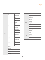
FaceStation
User Manual
Version V1.0
www.supremainc.com
Safety Information
Please ensure that the warnings and cautions below are followed in order to prevent risk and damage to property by correctly using the product.
Warning
Violation of the instructions may lead to serious injury or death.
Caution
Violation of the instructions may lead to minor injury or damage to the product.
Installation
Installation
Avoid places with direct sunlight, high humidity, dust or soot.
Do not leave a power cable or other cables in the passage way.
yy This may cause fire or electric shock.
yy This may damage the product or cause injury.
Install in a dry place.
Usage
yy Moisture may cause damage to the product or electric shock.
Do not press the touchscreen hard.
Install in a place with no heat such as a heater.
yy This may cause malfunction.
yy Overheating may cause fire or electric shock.
Do not place the product near objects with a strong magnetic field such as a magnet, CRT,
TV, monitor, or speaker.
Install in a place without electromagnetic interference.
yy This may cause malfunction.
yy This may cause damage to the product or electric shock.
Clean the product with a dry cloth; avoid benzene or alcohol.
Usage
yy Using chemicals or cleaning agents may deform the product.
Do not disassemble, repair or remodel this product.
Do not drop or apply physical shock.
yy This may cause fire, electric shock or injury.
yy This may cause malfunction.
Do not place a wet object or any object on the vent.
yy There is a risk of electric shock or fire; the product may malfunction if the vent is
covered.
Avoid liquids such as water, beverages and drugs from leaking into the product.
yy There is a risk of electric shock or fire; the product may be damaged.
2
Contents
1 Getting Started ....................................................................... 6
Connecting Fail Secure Lock ............................................................................................................19
Connecting with Automatic Doors ................................................................................................19
Features............................................................................................................................... 7
Connecting Inputs ...................................................................................................... 20
Components...................................................................................................................... 8
Connecting Wiegand ................................................................................................. 20
Name of Parts ................................................................................................................... 9
Connecting Wiegand Input ............................................................................................................. 20
Connecting Wiegand Output ..........................................................................................................21
2 Installation ............................................................................. 11
Connecting Mini USB ..................................................................................................21
Installation ...................................................................................................................... 12
Connecting USB ........................................................................................................... 22
Precautions for Installation ........................................................................................ 13
Connecting Video Phone ......................................................................................... 22
3 Connection ............................................................................ 14
4 Easy Use .................................................................................23
Connecting Power ....................................................................................................... 15
Registering Face ............................................................................................................24
Connecting with Wireless LAN ................................................................................ 15
Authenticating Face ....................................................................................................26
Connecting with Ethernet .........................................................................................16
Connecting with a PC ..........................................................................................................................16
5 Settings ..................................................................................27
Connecting with Hub ..........................................................................................................................16
Setting Menu Overview ........................................................................................... 28
Connecting RS485 ....................................................................................................... 17
User Management ...................................................................................................... 30
Connecting with a PC ........................................................................................................................... 17
Entering Administrator's Menu ........................................................................................................31
Connecting with Secure I/O and Other Devices ....................................................................... 17
Registering New User ......................................................................................................................... 32
Connecting RS232 ........................................................................................................18
Modifying User Information ............................................................................................................ 33
Connecting Relays ....................................................................................................... 19
Deleting User ......................................................................................................................................... 33
Connecting Fail Safe Lock ..................................................................................................................19
3
Contents
Deleting All Users ................................................................................................................................. 34
Checking Device Information ......................................................................................................... 46
Searching Users .................................................................................................................................... 34
Checking Memory Status ...................................................................................................................47
Checking User Capacity Information ........................................................................................... 35
TouchScreen Calibration ....................................................................................................................47
Setting Network ............................................................................................................35
Device Reset ............................................................................................................................................ 48
Setting TCP/IP ........................................................................................................................................ 36
Reset to Default ..................................................................................................................................... 48
Setting Server ......................................................................................................................................... 36
Setting Display and Sound .......................................................................................49
Setting Serial Communication .........................................................................................................37
Theme ...................................................................................................................................................... 49
Setting USB ..............................................................................................................................................37
Background ............................................................................................................................................ 49
Using USB Memory Device ............................................................................................................... 38
Voice Instruction .................................................................................................................................. 49
Using WLAN (Only for Wireless model) ................................................................ 38
Menu Timeout ....................................................................................................................................... 49
Setting Operation Mode ............................................................................................39
Pop-Up Time .......................................................................................................................................... 49
Setting Face Authentication ............................................................................................................ 39
Backlight Timeout ............................................................................................................................... 50
Setting Card Authentication ............................................................................................................ 40
Volume ..................................................................................................................................................... 50
Setting ID Authentication ................................................................................................................. 40
Language ................................................................................................................................................ 50
Setting Operations ...............................................................................................................................41
Central Time Display ............................................................................................................................ 50
Setting Time and Attendance ..........................................................................................................41
Date Display ........................................................................................................................................... 50
Setting Device ...............................................................................................................42
Viewing Logs .................................................................................................................. 50
Setting Face ............................................................................................................................................. 43
Log List ......................................................................................................................................................51
Setting Door............................................................................................................................................ 43
Log Search ................................................................................................................................................51
Setting Interphone ............................................................................................................................... 44
Delete All Log ........................................................................................................................................ 52
Setting Time............................................................................................................................................ 46
Log Info ..................................................................................................................................................... 52
4
Contents
6 How to Use ............................................................................53
Appendix .................................................................................. 60
Basic Screen View ......................................................................................................... 54
Specifications .................................................................................................................. 61
Face Authentication Screen ............................................................................................................. 54
Product Specifications .........................................................................................................................61
Home Screen ......................................................................................................................................... 54
Electric Specifications ..........................................................................................................................61
Device Status Screen ...........................................................................................................................55
Optional Accessories.............................................................................................................................61
When Face Authentication is Set ................................................................................................... 56
Cable Specifications .....................................................................................................62
When Card Authentication is Set .................................................................................................... 56
Power Cable ............................................................................................................................................ 62
When ID Authentication is Set ........................................................................................................ 56
232 Cable.................................................................................................................................................. 62
Face Authentication Types ............................................................................................................... 57
Relay Cable .............................................................................................................................................. 62
Card Authentication Types ............................................................................................................... 57
RS485 Cable ............................................................................................................................................ 62
ID Authentication Types .................................................................................................................... 58
Wiegand Cable ....................................................................................................................................... 63
Authenticating Time and Attendance ................................................................. 58
Video Phone Cable ............................................................................................................................... 63
Checking Time and Attendance .............................................................................59
Switch Cable .......................................................................................................................................... 63
Troubleshooting............................................................................................................ 64
FCC Rules ......................................................................................................................... 64
Device Font License ..................................................................................................... 64
Quality Assurance......................................................................................................... 66
Index ..................................................................................................................................67
5
1 Getting Started
Features
Components
Name of Parts
Getting Started
Features
4. 3" Touchscreen LCD
The 4.3” WVGA touchscreen LCD is mounted on the front of the product and provides an intuitive GUI. It makes the user management easy
while displaying various information including the time and attendance as well as notifications.
Next Generation Face
Recognition Technology
The state-of-the-art technology with Suprema’s proprietary algorithms stores both facial stamps using the visual camera and facial templates
using the IR camera. The seamless combination of the information gathered makes Suprema’s FaceStation the ultimate in facial recognition
technology with query speeds of up to 1:1000 matches per second.
Various Interface
Supported
You can connect with a PC and configure the network through various interfaces such as PoE, WiFi, TCP/IP, and RS485/232. Also, you can
configure various access control systems through Wiegand and input/output ports.
Video Phone
FaceStation's built-in camera, microphone, and speaker provides the device the ability to be integrated with conventional
analogue based videophones or IP based videophones to create a simple interphone system.
Various RF Cards Supported
Mifare Classic, Mifare Plus, and Mifare DesFire (CSN) cards are supported.
Powerful Dual-CPU
Architecture
A powerful 1.1GHz DSP is dedicated to handling facial template operations and a 667MHz RISC processor ensures uninterrupted device
operations.
7
Getting Started
Components
Wall Mounting Bracket (1)
Software CD (1)
Screws (4)
PVC Anchors (4)
Ferrite Core (1)
Power Cable (1)
232 Cable (1)
Relay Cable (2)
RS485 Cable (2)
Wiegand Cable (1)
Switch Cable (1)
Video Phone Cable (1)
Device
AC Power Cable (1)
DC Power Supply (1)
8
Getting Started
Name of Parts
Front
1
8
2
7
4
5
3
4
1
LCD Touchscreen
Used to display the device operating status and
device operation.
2
3
4
5
6
Call Button
Used to place a call on the interphone.
Light LED
Used as a general lighting.
Infrared (IR) LED
Used as an IR light.
Camera
Detects and captures a face image.
Proximity Sensor
Determines the user's proximity.
7
Basic T&A Button
(F1 - F4)
Selects Time and Attendance events.
8
Microphone
Used for speaking while connected via the
interphone.
Note
The RF cameras built in around the IR LED are used to detect an RF card.
5
6
9
Getting Started
Rear and Bottom
15
1
14
13
12
2
3
4
5
6
7
11
8
9
10
10
1
USB Wireless LAN
Terminal
Connects the USB wireless LAN.
2
Termination Resistor
Switch
Activates the RS485 terminal resistance.
3
4
5
6
7
8
PWR IN Terminal
Connects the power cable.
RS232 Terminal
Connects the RS232 3-pin connector.
9
Debug Terminal
RS485 Terminal
Connects the RS485 4 -pin connector.
Wiegand Terminal
Connects the Wiegand 5-pin connector.
Reset Button
Resets the device.
Mini USB Connect
Terminal
Connects with a PC.
10
Speaker
Outputs a voice on the device.
11
USB Connect
Terminal
Connects a USB memory device.
12
Switch Input
Terminal
Connects an input switch cable.
13
Phone Terminal
Connects a video phone cable.
14
Output Relay 1/2
Terminal
Connects Door Lock and output devices.
15
Ethernet Terminal
Connects an Ethernet cable.
2 Installation
Installation
Precautions for Installation
Installation
Installation
3
4
Since FaceStation has a built-in camera for face recognition and video interphone, the
installation height needs to be considered. Select a location to install the device by
considering the face capturing.
Mount the device on the fixed bracket.
Fix the fixing screws on the bottom of the device.
Installation
1
2
Fix the bracket at the desired location.
Drill a hole by using a drill and tools, insert anchors, and tightly fasten screws.
50cm
122cm
120cm
Note
• When installing the device for the first time, make sure to remove the transparent film from it.
Otherwise, it may affect adversely on the face recognition.
12
Installation
Precautions for Installation
Recommended Installation Height
yy
The optimal installation height is 120cm.
(Based on the user's height between 155cm - 205cm)
yy
It is recommended that you adjust the installation height based on the shortest person of
all the users.
yy
If you install devices for a same user group in many places, it is recommended that you
make all of them all the same height.
yy
It is recommended that you install the device by considering the recommended
installation height based on the bottom heights of device and bracket.
Recommended Installation Height
Range of User's Height
Bottom of the device
Bottom of the bracket
Minimum
Maximum
90cm
92cm
125cm
175cm
100cm
102cm
135cm
185cm
115cm
117cm
145cm
195cm
120cm
122cm
155cm
205cm
Installation Location
yy
The device must be installed indoors.
yy
When installing the device near a window, install the device at least 3 meters away from
the window.
yy
Avoid a place where there is direct sunlight on the face or from behind.
yy
Make sure not to install the device under incandescent light bulbs.
13
3 Connection
Connecting Power
Connecting Switch
Connecting with Wireless LAN
Connecting Wiegand
Connecting with Ethernet
Connecting Mini USB
Connecting RS485
Connecting USB
Connecting RS232
Connecting Video Phone
Connecting Relays
Connection
Connecting Power
Connecting with Wireless LAN
A model supporting the wireless LAN (WLAN) is equipped with a USB WLAN module upon
shipment.
USB
Wireless LAN
XVE#ṿ⑫#ODQ
Note
• The performance of WLAN is greatly affected by the surroundings and the type of the access point
(AP) in use.
• Some wireless AP may cause a problem when connecting with WLAN due to a hardware compatibility
issue.
15
Connection
Connecting with Ethernet
Connecting with a PC
Connecting with Hub
The device can communicate with a PC by directly connecting with the Ethernet cable.
The device can be connected with a regular hub or PoE hub by connecting the Ethernet
cable to the Ethernet terminal.
PoE (Power over Ethernet) is an Ethernet connection of which the power is supplied from
PSE (Power Sourcing Equipment) satisfying the IEEE802.3af standard.
Regular hub or
Ethernet hub
16
Connection
Connecting RS485
Connecting with Secure I/O and Other Devices
By using the RS485 wiring, several devices can be connected with a PC or a device can be
connected with a secure I/O or another device.
Connecting with a PC
RS485 CH1
PIN1: GND (Black)
PIN2: TRXD - (Yellow)
PIN3: RS TRXD + (Blue)
1
2
3
RS485 CH1
PIN3: RS-GND(Black)
PIN2: RS485-TRX-(Yellow)
PIN1: RS485-TRX+(Blue)
RS232-485
Converter
PIN3: RS-GND(Black)
PIN2: RS485-TRX-(Yellow)
PIN1: RS485-TRX+(Blue)
RS485 CH0
PIN3: RS-GND (Black)
PIN2: RS485-TRX-(Yellow)
PIN1: RS485-TRX+(Blue)
4 5 6
4 5 6
PIN6: RS485 TRX+(Blue)
PIN5: RS485 TRX-(Yellow)
PIN4: RS-GND (Black)
RS485 CH0
PIN3: RS-GND (Black)
PIN2: RS485-TRX-(Yellow)
PIN1: RS485-TRX+(Blue)
17
Connection
Connecting RS232
Note
• When the RS485 wiring is long, turn on the dip switch to add terminating resistance in order to
prevent weakening of the signal and to properly deliver the signal.
The device can be connected with a PC through RS232 wiring.
Switch On
PIN2: RXD (Green)
PIN3: TXD (Yellow)
PIN5: GND (Black)
5
3
2
Switch Off
PIN1: RS-GND (Black)
PIN2: RS232-TX (Yellow)
• When the wiring is too short, adding resistance affects the signal. By considering the length of the
cable and signal status, turn on/off the termination resistor switch.
• If GND is not connected, either the RS485 chip may be damaged or it may not properly communicate.
• The RS485 communication between devices can be configured with 1 host device and up to 7 slave
devices. When configuring such communication, up to 4 Secure I/O can be connected.
1
18
2
3
PIN3: RS232-RX (Green)
Connection
Connecting Relays
Connecting with Automatic Doors
Connecting Fail Safe Lock
PIN3: N/C(Normal Close: Orange)
PIN2: Common(Blue)
PIN1: N/O(Normal Open: White)
PIN3: N/C(Normal Close: Orange)
PIN2: Common(Blue)
Deadbolt or
Door strike
DC
Power supply
Deadbolt or
Door strike
DC
Power supply
Connecting Fail Secure Lock
PIN1: N/O(Normal Open: White)
RTE Switch
PIN3: N/C(Normal Close: Orange)
PIN2: Common(Blue)
PIN3: N/C(Normal Close: Orange)
PIN1: N/O(Normal Open: White)
PIN2: Common(Blue)
PIN3: N/C(Normal Close: Orange)
PIN1: N/O(Normal Open: White)
PIN2: Common(Blue)
Deadbolt or
Door strike
DC
Power supply
Deadbolt or
Door strike
DC
Power supply
PIN1: N/O(Normal Open: White)
Presence Detector
Note
• Normally Open/N.O: The electricity does not flow when there is no control signal but flows when
there is a control signal.
• Normally Close/N.C: The electricity flows when there is no control signal but does not flow when there
is a control signal.
19
Door Controller
Connection
Connecting Wiegand
Connecting Inputs
Connecting Wiegand Input
3
8
7
6
5
4
3
2
2
1
PIN3: Wiegand GND (Black)
PIN2: Wiegand DATA1 (White)
PIN1: Wiegand DATA0 (Green)
1
Cable Shield
(Optional)
Cable Shield
(Optional)
PIN8: Shield GND (Gray)
PIN7: Switch GND (Black)
PIN6: Switch Input3 (Orange)
PIN5: Switch Input2 (White)
PIN4: Shield GND (Gray)
PIN3: Switch GND (Black)
PIN2: Switch Input1 (Green)
PIN1: Switch Input0 (Yellow)
Cable Shield
(Optional)
Card Reader
Switch
Input 3
Switch
Input 2
Switch
Input 1
GND
Wiegand Output.Data1
Wiegand Output.Data0
Switch
Input 0
Note
• Since there is a single Wiegand port, set to either input mode or output mode on the BioStar software.
20
Connection
Connecting Mini USB
Connecting Wiegand Output
The device can be directly connected with a PC through the mini USB port.
3
2
1
PIN3: Wiegand GND (Black)
PIN2: Wiegand DATA1 (White)
PIN1: Wiegand DATA0 (Green)
Cable Shield
(Optional)
Access Controller
GND
Wiegand Output.Data1
Wiegand Output.Data0
21
Connection
Connecting USB
Connecting Video Phone
You can upload or download data from a USB memory device.
PIN 6 : GND (Black)
PIN 5 : Door Open (Orange)
PIN 4 : Video Signal (White)
PIN 3 : Power (Yellow)
PIN 2 : GND (Blue)
PIN 1 : Voice Signal (Red)
6
5
4 3
S2
S1
4
3
Note
2
• Some USB memory devices may not be recognized due to a hardware compatibility issue.
1
Note
• The videophones compatible with FaceStaion are as below;
COMMAX/ CAV-35N, COMMAX/ CAV-50H, COMMAX/ CAV-50P
22
2
1
4 Easy Use
Registering Face
Authenticating Face
Easy Use
Registering Face
2
Move your face up and down.
3
Move your face back and forth.
Go to Menu > User > Enroll User and press Face in order to register a face for
authentication.
Registration Method
1
Stare at the screen.
Note
• When a face is detected on the sensor of the device, the orange guide line turns to blue.
• Follow the face recognition instructions until the dotted circle on the left of the screen is completed.
24
Easy Use
4
• When moving your face up and down
Move your face right and left.
• When moving your face left and right
5
Press OK to complete the registration.
Press Cancel to cancel the face registration.
Precautions for Registration
• It is recommended that you register your face at the installation site.
• Register an expressionless face.
• It is recommended that you keep the distance of about 40 to 80 cm from the device screen when
registering your face.
• When initially registering the front of the face, the authentication performance may be deteriorated if
you face up. Make sure to stare at the screen.
• When initially registering the front of the face, the registration may take longer if no movement is
detected. When registering the front of the face, slightly move the face.
• When moving the face back and forth, step back and forth in order to improve the authentication
performance.
• Make sure to take off a hat and to make the face with the eyebrows exposed in order not to cover the
lower part of the face with hairs.
• If a user frequently switches between wearing glasses and no glasses, change the look of wearing
glasses when registering left and right images.
• Make sure that more than two people's faces should not be registered on the screen at the same time.
• If the face moves up, down, left, or right or if the instructions for moving the face forward or backward
are not followed while registering, the registration may take longer. Please follow the registration
instructions.
• When moving your face back and forth
25
Easy Use
Authenticating Face
2
The authentication completion screen is displayed if the user authentication is
completed.
When Menu > Mode > Face Auth Mode > Face is set as Always, the authentication screen is
activated when the user is in close proximity to the device.
Authentication Method
1
Align your face with the orange guide line turns to blue, circular line on the
authentication screen.
When the orange guide line turns to blue, keep your face still while aligned
with the blue line and wait until the authentication is complete.
Note
• When authentication is completed on the face authentication screen after you press Menu, you can
enter the Administrator’s menu.
Precautions for Authentication
• Position the face within the orange circle on the screen.
• If the authentication takes too long, either move the chin up and down or step back and forth.
• If hairs on the side covers a part of the face including the eyebrows, the authentication may not
perform well. It is recommended that you authenticate the face with the eyebrows exposed.
• If the user changes glasses, the authentication may fail. It is recommended to re-enroll the user's
face with new glasses.
• When wearing sunglasses, the authentication is not possible. It is recommended you take it off before
authentication.
Note
Precautions for Usage
• When a face is detected on the sensor of the device, the orange guide line turns to blue on the
authentication screen. Do not move your face while the authentication is in progress.
• Make sure to keep the distance of 50cm from the device when authenticating the face.
• It is recommended you set the Authentication mode to 'Card+Face' or 'ID+Face' in order to
strengthen the authentication security.
• It is recommended you set the Authentication mode to 'Card+Face' since the authentication for twin
users may not be correct.
• If the user's facial facial appearance has changed dramatically (such as plastic surgery or shaving
bushy beard), it is recommended to re-enroll the user.
26
5 Settings
Setting Menu Overview
Setting Device
Setting Users
Setting Display and Sound
Setting Network
Viewing Logs
Using WLAN
Setting Operation Mode
Easy Use
Setting Menu Overview
User
Enroll User
Face
Edit User
Face+Pin
Search
Face Auth Mode
User Capacity Info
Delete All Users
Face+Pin > T&A Key
Port
Card Only
Max Conn
Card+PIN
DHCP
Card Auth Mode
IP Address
Subnet
Card+Face+PIN
Mode
Use Server
Network
Server IP
ID+PIN
ID Auth Mode
Port
RS485-PC
Serial
RS485-NET
ID+Face/PIN
Face Detection
Dual Authentication
USB
Operation
USB Memory
Card Mode
Individual Auth
Import
USB Memory
ID+Face
ID+Face+PIN
RS232
USB
Card+Face
Card+Face/PIN
Gateway
Server
T&A Key > Face+PIN
Face > T&A Key
LAN Type
TCP/IP
T&A Key > Face
Match Timeout(sec)
Export
T&A
Firmware Upgrade
Camera Event
WLAN
28
Easy Use
Face
Security Level
Theme
Enrollment Sensitivity
Background
Relay
Voice Instruction
Driven By
Menu Timeout
Duration
Display
RTE(Exit SW)
RTE Type
Door
Language
Central Time Display
Held Open Period(sec)
Unlock Time
Date Display
Lock Time
Log List
Exit Relay Device ID
Log
Interphone
Interphone
VoIP Setting
Log Search
Delete All Log
Log Info
BS VideoPhone Setting
Date
Date & Time
Backlight Timeout
Volume
Door Sensor
Door Sensor Type
Device
Pop-Up Time
Time
Time Sync
Device Info
Memory Info
Touchscreen Calibration
Reset
Factory Default
29
Settings
User Management
Register the administrator's picture.
1) Press the Face image window for registering the administrator's face picture.
2) Align your face in the screen and press Capture. The captured face image
will be registered.
Press Cancel to cancel the registration.
After the device installation, register the administrator before use. The administrator can
register and delete users and set preferences.
2
Face
Image
window
3
Registering Administrator
y User ID
Enter the user ID.
y Name
Enter your name and press OK.
y Faces
Register your face. For details regarding face registration,
please refer to 'Registering Face(page 24)'.
y Card
Enter the ID and press OK.
y PIN
Enter the pin number and press OK.
y Administrator
Select the administrator level.
Setup
1
Go to Menu > User > Enroll User.
4
30
Press
. The administrator will be registered.
Settings
Entering Administrator's Menu
Go to the administrator's menu and set each item.
Setup
1
Press Menu on the Home screen. The administrator's menu is displayed.
3
1) Scan the face or enter the card.
2
Note
• If you press Menu while no user is registered, the administrator's menu is displayed without any
authentication process.
• When a general user follows the process to enter the administrator's menu, the user can view the
event log for the time and attendance.
• Regardless of a previously set authentication mode, you can move to the administrator's menu by
Face authentication, Card authentication, and ID + Face/Pin authentication.
2) Enter the ID. And enter the pin number or face.
31
Settings
Registering New User
3
You can register a new user on the device.
Face
Image
window
1
y User ID
Enter the user ID.
y Name
Enter your name and press OK.
y Faces
Register your face. For details regarding face registration,
please refer to 'Registering Face(page 24)'.
y Card
Enter the card ID by placing the card on the device.
y PIN
Enter the pin number and press OK.
y Administrator
Check on the administrator level to register as the
administrator.
Uncheck if registering as a general user.
y Bypass Card
If Bypass Card is checked when registering a user,
the user is always authenticated regardless of the
authentication mode on the device.
y Individual Auth
A user registered with this mode is authenticated with
the individually selected authentication mode instead of
the device authentication mode.
The set individual authentication mode works only for
the relevant authentication method. For higher security,
it is recommended to set either 'Card+Face' or 'ID+Face'.
For twins, it is recommended to set either 'Card+Face' or
'ID+Face'. After setting the mode, press OK.
y Group
The access of group users can be set. A group can be
selected from Access groups transferred from the BioStar
software to the relevant device. After setting, press OK.
Go to Menu > User > Enroll User.
Register the user's picture.
1) Press Face Image window for registering the user's picture.
2) Align your face in the screen and press Capture. The captured facial image
will be registered.
Press Cancel to cancel the registration.
2
4
32
Press . You can register a new user.
Press
or
to exit without saving the changes. You can go to the previous
screen or Home screen.
Settings
Modifying User Information
Deleting User
You can modify the registered user information.
You can delete the desired user.
Setup
1
2
Go to Menu > User > Edit User.
Check a user to delete.
Press
.
3
Setup
1
2
3
Go to Menu > User > Edit User.
Select a user by pressing the user name field.
Modify the desired information.
Press Yes to delete the selected user.
Press
to save the modified information.
Press
or
to exit without saving the changes. You can go to the previous
screen or Home screen.
Press No to cancel the deletion.
4
Note
• The user ID cannot be modified.
33
Settings
Deleting All Users
Searching Users
You can delete all registered users.
You can search the registered users.
Setup
1
2
Setup
1
2
Press Menu > User > Delete All Users.
Press Yes to delete all registered users.
Press No to cancel the deletion.
Go to Menu > User > Search.
y Search by ID
Enter an ID and press OK.
y Search by Name Enter a name and press OK.
y Search by CSN
Note
• When a user is deleted while not saved on the BioStar software database, the user cannot be restored.
34
3
Enter the card.
Press OK to display the search results.
Press Cancel to cancel the search.
Settings
Setting Network
Checking User Capacity Information
You can view the registration information (total number of registered users, total number of
registered user's images, and number of templates).
You can set the communication method of the device.
Setup
1
2
Setup
1
2
3
Go to Menu > User > User Capacity Info.
Press OK to return to the previous screen.
Note
• Up to 10,000 users along with their images can be stored.
35
Go to Menu > Network.
Set the options.
Press
or
to go to the previous screen or Home screen.
Settings
Setting TCP/IP
Setting Server
When the device and BioStar software is connected via TCP/IP method, you can set the
relevant settings.
You should set the IP address and port of the server to connect in order to communicate
with it.
1
2
3
Go to Menu > Network > TCP/IP.
1
2
Set the options.
y LAN Type
Set the connection method and press OK.
y Port
Enter the port and press OK.
y Max Conn
Set the maximum number of clients to be concurrently
connected with the device and press OK.
y DHCP
Check to enable DHCP.
y IP Address
Enter an IP address if a static IP address is used and press
OK. If DHCP is checked, this item is not activated.
y Gateway
Enter a gateway address if a static IP address is used and
press OK. If DHCP is checked, this item is not activated.
y Subnet
Enter the subnet mask if a static IP address is used and
press OK. If DHCP is checked, this item is not activated.
Press
or
3
to go to the previous screen or Home screen.
36
Go to Menu > Network > Server.
Set the options.
y User Server
Check to use the server.
y Server IP
Enter the server's IP address and press OK.
It can be set if User Server is checked.
y Port
Enter the server's port and press OK.
It can be set if User Server is checked.
Press
or
to go to the previous screen or Home screen.
Settings
Setting Serial Communication
Setting USB
When the device is connected by RS485 or RS232, you can set the connection-related
options.
Setup
Setup
1
2
Set the options and press OK.
y RS485-PC
You can enable/disable the RS485 port to connect with a
PC and set the communication speed.
y RS485-NET
Enable or disable the RS485 port for communications
between devices and set the communication mode.
You can add the device as a host by setting RS485-NET
to NET-HOST, and as a slave by setting it to NET-SLAVE.
y RS232
3
1
2
Go to Menu > Network > Serial.
Press
or
3
It can be set if RS485 is disabled. You can enable/disable
the RS232 port to connect with a PC and set the
communication speed.
to go to the previous screen or Home screen.
Note
• The RS485 communication between devices can be configured with 1 host device and up to 7 slave
devices including up to 4 Secure I/O.
37
Go to Menu > Network > USB.
Set the options.
y USB
Set to allow the connection with a PC via USB.
y USB Memory
Set to allow the connection with a USB memory device.
Press
or
to go to the previous screen or Home screen.
Settings
Using WLAN (Only for Wireless models)
Using USB Memory Device
When setting to make USB available, you can select options to conduct the desired
operations with the USB memory device.
You can select one of 4 WLAN preset options previously saved from BioStar. On BioStar, you
can set the preset options including SSID, encryption method, encryption key, etc.
Setup
1
2
3
Setup
Go to Menu > Network > USB Memory.
1
2
3
Select an option.
y Import
Select a device ID to import data and press OK.
y Export
Press Export and wait until the job is completed.
y Firmware Upgrade
Select firmware to upgrade and press OK.
Press
or
to go to the previous screen or Home screen.
Note
• The USB Memory needs to be checked from Menu > Network > USB in order to activate the USB
Memory menu.
38
Go to Menu > Network > WLAN.
Check the preset option to use for WLAN connection.
Press
or
to go to the previous screen or Home screen.
Settings
Setting Operation Mode
Setting Face Authentication
You can set operations related to each authentication or view the Time and Attendance
events. The authentication mode operates according to the set timezone. Up to 128
timezones for setting authentication mode can be set on BioStar.
Setup
1
2
Setup
1
2
3
Go to Menu > Mode.
Set the options.
Press
or
to go to the previous screen or Home screen.
3
4
39
Go to Menu > Mode > Face Auth Mode.
Select a desired option.
y Face
Authenticates with a face only.
y Face + Pin
Authenticates with both face and pin number.
y T&A Key > Face
Authenticates with both the T&A key and the face.
y T&A Key > Face + Pin
Authenticates with the T&A key, face, and pin
number.
y Face > T&A Key
Authenticates with both the face and the T&A key.
y Face + Pin > T&A Key
Authenticates with face, pin number, and the T&A
key.
Check Never or Always to set the apply time.
Press
or
to go to the previous screen or Home screen.
Settings
Setting Card Authentication
Setting ID Authentication
Setup
Setup
1
2
3
4
1
2
Go to Menu > Mode > Card Auth Mode.
Select a desired option.
Go to Menu > Mode > ID Auth Mode.
Select a desired option.
y ID + Pin
Authenticates with both ID and pin number.
y Card Only
Authenticates with a card only.
y ID + Face
Authenticates with both ID and face.
y Card + Pin
Authenticates with both card and pin numberd.
y ID + Face/Pin
y Card + Face
Authenticates with both card and face.
Authenticates with both ID and either face or
pin number.
y Card+ Face/Pin
Authenticates with both card and either face or
pin number.
y ID + Face + Pin
Authenticates with ID, face, and pin number.
y Card + Face + Pin
Authenticates with card, face, and pin number.
3
4
Check Never or Always to set the apply time.
Press
or
to go to the previous screen or Home screen.
40
Check Never or Always to set the apply time.
Press
or
to go to the previous screen or Home screen.
Settings
Setting Operations
Setting Time and Attendance
Setup
1
2
Go to Menu > Mode > Operation.
Check, or set the options and press OK.
y Face Detection
y Dual Authentication
y Card Mode
y Individual Auth
y Match Timeout(sec)
3
Setup
Press
or
1
2
On face authentication, stores the detected face image as
an image log. On ID or card authentication, additionally
authenticates and stores the detected face image as an
image log. If no face is detected, the authentication will end
up in failure.
Authenticates with faces, cards, and IDs of two people.
The entry relay operates only when two different users are
authenticated, and the second user should be authenticated
within 15 seconds after the first user is authenticated. If
15 seconds has passed after the first authentication, the
authentication is invalidated and the status is initialized.
Sets whether to use the CSN card for authentication.
Authenticates by customized methods for each individual.
When registering a new user from Menu > User > Enroll
User, the private authentication can be set. Please refer to
'Registering New User(page 32)' for details.
Set the T&A options.
y Disabled
Select to use the access authentication without
using Time and Attendance. The the T&A button
disappears on the Home menu and the CALL
button is activated.
y Manual(by key input)
For every authentication, press either the T&A
buttons (F1 - F4) or the T&A event button (
T&A) to select an event. The selected Time
and Attendance event is deselected after the
authentication.
Sets the authentication time-out period. If a user is not
authenticated within the set period, the authentication fails.
to go to the previous screen or Home screen.
Go to Menu > Mode > T&A > T&A.
41
Settings
y Auto(by time schedule)
Setting Device
The Time and Attendance event of the
corresponding timezone is automatically
applied when authenticating. When changing
to a different event instead of the event of the
corresponding timezone, press the T&A button
(F1 - F4) to select a particular event.
You can set options for the device authentication and operations.
y Manual Fix(by key input) Select a Time and Attendance event by
pressing either one of F1 - F4 buttons or an
additional T&A event button (
T&A) when
authenticating. The selected event is maintained
until another event is selected, while the event
is deselected after the authentication when
manually changing.
y Fixed(by device)
3
A user can be authenticated with a fixed Time
and Attendance event but cannot select other
events.
Press OK to save the changes.
Setup
Press Cancel to cancel any changes.
1
2
3
42
Go to Menu > Device.
Set the options.
Press
or
to go to the previous screen or Home screen.
Settings
Setting Face
Setting Door
Setup
Setup
1
2
1
2
Go to Menu > Device > Face.
Set the options.
y Security Level
Increasing the security level will indirectly
increase the FRR(False Reject Rate, probability
that the system will incorrectly reject an access
attempt by an authorized user) because the
stricter authentication protocols will reject more
inconsistencies. Select the desired security level and
press OK.
Go to Menu > Device > Door.
Set the options and press OK.
y Relay
Sets a relay to use for the door when authenticating a
user.
y Driven by
Sets an event to open the door.
y
All Events: Opens the door for all authentication
modes.
y
Authentication: Opens the door only for regular
authentication but not for the Time
and Attendance authentication.
y
T&A Event: Opens the door for an event with a relay
enabled during the Time and Attendance
authentication.
y Enrollment Sensitivity Select the desired enrollment speed and press OK.
3
Press
or
to go to the previous screen or Home screen.
43
Settings
y
y
3
Sets the opening time of the door relay when an event
occurs. The door relay closes after the set time.
y RTE(Exit SW)
Select the input to be used for the door opening
switch.
y RTE Type
Select the operation method for the door opening
switch. (N/C: Normally Closed; N/O: Normally Open)
y Door Sensor
Select the input to be used for detecting the door
opening.
y Door Sensor Type
Select the operation method for the door opening
switch. (N/C: Normally Closed; N/O: Normally Open)
y Held Open
Period(sec)
Sets a period of time from opening the door to displaying
the opening warning event.
y Unlock Time
Sets a period of time to leave the door open. During
this period, the door does not close. The period can be
set on BioStar software.
Press
or
When the interphone is set, you can make a video call by pressing the CALL button.
Disabled: Sets to disable opening the door for all
Time and Attendance events.
y Duration(sec)
y Lock Time
Setting Interphone
Authentication + : Opens the door for an event
T&A Event
with a relay enabled during both
general authentication and Time
and Attendance authentication.
Setup
1
2
3
Sets a period of time to lock the door. The period can
be set on BioStar software.
to go to the previous screen or Home screen.
44
Go to Menu > Device > Interphone.
Set the options.
Press
or
to go to the previous screen or Home screen.
Settings
Interphone
Select an interphone to use and press OK.
yy VoIP Server IP: Enter the VoIP IP address and press OK.
yy VoIP Phone Number: Enter the VoIP phone number and press
OK.
yy VoIP Server ID: Enter a VoIP server ID and press OK.. Korean,
English, number, and special characters can be
used for an ID.
yy VoIP Server Password: Enter a VoIP server password and press
OK.
yy VoIP Mic Gain: Adjusts the VoIP microphone volume. (0 - 10)
yy VoIP Speaker Gain: Adjusts the VoIP speaker volume. (0 - 10)
yy VoIP Display Name: Enter the VoIP name to be displayed on the
screen and press OK.
VoIP Setting
BS VideoPhone
Setting
When the IP interphone is set, the relevant options can be set.
When the BioStar Video Phone is set, the relevant options can be set.
yy Mode: Select either single or extension mode and press OK.
yy PIN: Enter a pin number for the BioStar video phone and press OK.
yy Door Control: Enables or disables the door control on the
BioStar video phone.
3
45
Press
or
to go to the previous screen or Home screen.
Settings
Setting Time
Checking Device Information
You can view the device information such as the model name, device ID, hardware version,
firmware version, kernel version, MAC, face module version, face module (FD) version, and
face module (LDA) version.
Setup
1
2
3
Go to Menu > Device > Date & Time.
Setup
Set the options.
y Date
Set the year, month, and day, and press OK.
y Time
Set AM/PM, hour, minute, and second, and press OK.
y Time Sync
Can be set only if the device is connected with a server.
You can synchronize the time on the device with the
server. The time is synchronized every hour when the
difference between the BioStar server and device is more
than 5 seconds.
Press
or
1
2
3
to go to the previous screen or Home screen.
46
Go to Menu > Device > Device Info.
View the option.
Press
or
to go to the previous screen or Home screen.
Settings
Checking Memory Status
TouchScreen Calibration
You can check the memory status of DRAM, FLASH, and FLASH2.
If the screen does not function when touched or a touch point does not correctly
correspond, you can calibrate the screen.
Setup
1
Go to Menu > Device > Touch Calibration.
2
Press and hold the center of the touch point on the screen until the completion
message appears.
Carefully press and briefly hold stylus on the center of the target.
Repeat as the target moves around the screen.
Press the Esc key to cancel.
Setup
1
2
3
Go to Menu > Device > Memory Info.
View the option.
Press OK to return to the previous screen.
2
47
Press OK. The screen calibration is complete.
Settings
Device Reset
Reset to Default
Setup
1
2
Setup
1
Go to Menu > Device > Reset.
Press Yes to restart the device.
2
Press No to return to the previous screen.
Go to Menu > Device > Factory Default.
Press Yes to initialize the device.
Press No to return to the previous screen.
Note
• Please note that initializing the device will delete all information such as downloaded backgrounds
and sounds through BioStar software as well as announcements. The initialization does not delete the
registered user information and log data.
48
Settings
Setting Display and Sound
Theme
You can set the background theme of the device.
Select among Red, Blue, Black, Rainbow, and Custom, and press OK.
Background
You can set the device background to be displayed.
Select among Logo, Notice, Slide Show, and PDF, and press OK.
Note
• When the background is set for Logo, Slide, or PDF, the logo screen is displayed during the
authentication and other operations while the announcement, slide show or PDF screen appears
after the menu time-out period (30 seconds if set to Always On). When touching the screen while
an announcement or slide show is on, the LCD backlight turns on if it was off or a logo screen is
displayed if the LCD backlight was on.
Setup
1
2
3
Voice Instruction
Go to Menu > Display.
You can enable the voice guide on the device.
Set or check by pressing the relevant option.
Press
or
to go to the previous screen or Home screen.
Menu Timeout
You can set the amount of idle time (sec) before the menu disappears.
Select among Infinite, 10 sec, 20 sec, and 30 sec, and press OK.
Pop-Up Time
You can set the duration (sec) before the popup window disappears.
Select among 0.5 sec, 1 sec, 2 sec, 3 sec, 4 sec, and 5 sec, and press OK.
49
Settings
Viewing Logs
Backlight Timeout
You can set the amount of idle time before the backlight turns off.
You can view, search or delete the event log.
Select among Infinite, 10 sec, 20 sec, 30 sec, 40 sec, 50 sec, and 60 sec, and press OK.
Volume
You can set the volume output of the device.
Select among 0, 10, 20, 30, 40, 50, 60, 70, 80, 90, and 100, and press OK.
Language
You can set the display language.
Select among Korean, English, and Custom, and press OK.
Central Time Display
Setup
You can set to enable or disable the time on the screen.
1
2
3
Date Display
You can set the date format.
Select MM/DD or DD/MM, and press OK.
50
Go to Menu > Log.
Press and view the option.
Press
or
to go to the previous screen or Home screen.
Settings
Log List
Log Search
You can select and view the desired event log.
You can search and view logs by starting date, starting time, ending date, ending time,
event, Time and Attendance event, or user ID.
Setup
Setup
1
2
3
Go to Menu > Log > Log List.
1
2
3
4
View a desired log.
Press
or
to go to the previous screen or Home screen.
51
Go to Menu > Log > Log Search.
Set the search items and press OK.
Press
to display the searched log.
Press
or
to go to the previous screen or Home screen.
Settings
Delete All Log
Log Info
You can delete the entire log at once.
You can view the log and face image log currently stored on the device.
Setup
1
2
Setup
1
2
Go to Menu > Log > Delete All Log.
Press Yes to delete all logs.
Press No to cancel the log deletion.
Go to Menu > Log > Log Info.
Press OK to return to the previous screen.
Note
• Up to 1,000,000 regular logs and up to 5,000 face image logs can be stored.
52
6 How to Use
Basic Screen View
Authenticating Time and Attendance
Checking Time and Attendance
How to Use
Basic Screen View
Home Screen
Face Authentication Screen
If face authentication is not set from the operation mode or the camera does not detect any
motion, the Home screen is displayed.
If face authentication is set, the screen as shown below appears.
10
9
8
1
9
8
2
7
6
1
2
3
7
6
4
5
4
3
5
1
Status Button
Checks for the connection status of the device and
whether or not the face recognition is enabled.
2
Additional T&A
Button
Selects 12 Time and Attendance buttons in addition
to 4 basic Time and Attendance.
Menu Button
Enter the Administrator's Menu.
Call Button
Used for a video phone call.
Image Display Screen Displays an image from the camera as well as the face.
3
4
5
Basic T&A Button
Displays basic Time and Attendance events.
Authentication Guide
Displays available authentication methods.
6
ID Authentication
Button
Enter the ID input window for ID authentication.
8
T&A Event
Displays the set Time and Attendance event. When entering the
administrator's menu, a message 'Enter the administrator's menu' appears.
7
Goes to the face authentication screen.
9
Face Authentication
Button
Current Time
Displays the current time on the device.
Displays the Time and Attendance event.
Displays the guide line for face detection.
8
9
T&A Event
Face Detection
Guide Line
Status Bar
Displays the current date and time on the device.
1
2
3
4
5
6
7
Home
Goes to the Home screen.
ID
Goes to the ID authentication screen.
T&A
Selects Time and Attendance options.
Menu
Goes to the Administrator's menu.
Face Detection Icon
Displays the face detection availability.
10
54
How to Use
Device Status Screen
Note
When the face recognition and all connection status are successfully set, a screen as shown below is
displayed.
1
4
3
2
1
Serial
Displays the connection status with a host when in
RS485 slave mode.
2
PC Connection
Displays the connection status with a PC through
Ethernet or WLAN.
3
Network Connection
Displays the connection status of the Ethernet or
WLAN.
4
Face Detection
Displays whether or not the face recognition is
enabled.
55
How to Use
Access Authentication
When ID Authentication is Set
When the ID is set as the authentication option from Menu > Mode > ID Auth Mod, the ID
authentication is operated during the corresponding timezone.
FaceStation supports the face, card (RFID), and ID (PIN) authentication. The authentication
mode operates according to the set timezone, and each authentication timezone does
not overlap. Up to 128 timezones for setting authentication mode can be set on BioStar PC
software.
Please refer to 'Setting ID Authentication(page 40)'for details regarding ID
authentication settings.
When Face Authentication is Set
When the face is set as the authentication option from Menu > Mode > Face Auth Mode,
the face authentication is operated during the corresponding timezone.
For details regarding the face authentication, please refer to 'Authenticating Face(page 26)'.
When Card Authentication is Set
When the card is set as the authentication option from Menu > Mode > Card Auth Mod, the
card authentication is operated during the corresponding timezone.
For details regarding the card authentication settings, please refer to 'Setting Card
Authentication(page 40)'.
56
How to Use
Face Authentication Types
Card Authentication Types
Face
1
Card Only
1
Scan the face.
Face + Pin
1
2
Card + Pin
1
2
Scan the face.
Enter the pin number and press OK.
T&A Key > Face
1
2
1
2
Press the T&A button.
Scan the face.
Enter the card ID by placing the card on the device.
Scan the face.
Press the T&A button.
1
Enter the card ID by placing the card on the device.
Scan the face.
2
Scan the face.
Or, enter the pin number and press OK.
Enter the pin number and press OK.
Card + Face + Pin
1
2
3
Scan the face.
Press the T&A button.
Face + Pin > T&A Key
1
2
3
Enter the pin number and press OK.
Card+ Face/Pin
Face > T&A Key
1
2
Enter the card ID by placing the card on the device.
Card + Face
T&A Key > Face + Pin
1
2
3
Enter the card ID by placing the card on the device.
Scan the face.
Enter the pin number and press OK.
Press the T&A button.
57
Enter the card ID by placing the card on the device.
Scan the face.
Enter the pin number and press OK.
How to Use
Authenticating Time and Attendance
ID Authentication Types
ID + Pin
1
2
Setup
Enter the ID and press OK.
1
Enter the pin number and press OK.
Either press the T&A key(F1 - F4) or select an event on the screen.
ID + Face
1
2
Enter the ID and press OK.
Scan the face.
T&A key
ID + Face/Pin
1
Enter the ID and press OK.
2
Scan the face.
Or enter the pin number and press OK.
ID + Face + Pin
1
2
3
Enter the ID and press OK.
Scan the face.
Enter the pin number and press OK.
Perform the authentication process.
2
Please refer to 'Access Authentication(page 56)' for details regarding the
face, card and ID authentication processes.
Note
• If the Time and Attendance is set as fixed or manual, the Time and Attendance event does not need
to be separately selected. Please refer to 'Setting Time and Attendance(page 41)' for details
regarding Time and Attendance.
58
How to Use
Checking Time and Attendance
2
Enter the registered face, card and/or ID. The Time and Attendance log list is
displayed.
The user can view the access and attendance records.
Setup
1
Press Menu.
Note
• The general user can view the Time and Attendance log through the said method, while the
administrator can go to the administrator's menu through the said method.
59
Appendix
Specifications
Cable Specifications
Troubleshooting
FCC Rules
Device Font License
Quality Assurance
Index
Appendix
Specifications
Optional Accessories
Secure I/O
Mifare reader/writer
Product Specifications
10,000
Max Users
1,000,000
Log Capacity
Image Log Capacity
CPU
1.1GHz DSP, 667MHz RISC
LCD
4.3” WVGA Touchscreen
Memory
4GB Flash + 512MB RAM
System
General
PIN 6 : GND (Black)
PIN 5 : Door Open (Orange)
PIN 4 : Video Signal (White)
PIN 3 : Power (Yellow)
PIN 2 : GND (Blue)
PIN 1 : Voice Signal (Red)
10,000
RF Options
13.56MHz Mifare
Interfaces
TCP/IP, RS485(2ch), RS232, USB, Wiegand, WiFi
Power
FaceStation
(W x H x D)
Dimensions
Wall Bracket
(W x H)
12VDC, PoE (Power over Ethernet)
Switch
Input
4 3
2
1
Wireless AP
S1
132 x 165 x 60 mm
97 x 107.8 mm (screw joint included)
4
3
2
1
Min.
Avr.
Max.
Voltage(V)
10.8
12
13.2 Make sure to use only the supplied power supply.
Current(mA)
-
VIH(V)
-
TBD
VIL(V)
-
TBD
-
4.7K
-
-
-
Pullup Resistor
Switching
Capacity(A)
Switching
Relay
Power
(resistive)
Switching
Voltage(V)
5
S2
Electric Specifications
Power
6
Video phone
Description
RF Card
1500
2
0.3
The input ports are pulled up with 4.7K resistors.
30V DC
125 AC
-
30W
37.5VA
DC
AC
-
110
125
DC
AC
RF
61
Plastic Stand
Appendix
Cable Specifications
Power Cable
Relay Cable
Pin
Name
1
POW +
2
POW -
Cable Type
AWG24
Color
Pin
Name
1
RELAY NORMAL
OPEN
2
RELAY COMMON
3
RELAY NORMAL
CLOSE
Color
Pin
Name
GREEN
1
RS485 TRX+
YELLOW
2
RS485 TRX-
BLACK
3
GND
4
SHIELD GND
RED
BLACK
232 Cable
Cable Type
Color
WHITE
AWG24
BLUE
ORANGE
RS485 Cable
4
Pin
Name
1
232RX
2
232TX
3
GND
Cable Type
AWG26
62
Cable Type
Color
BLUE
AWG26
YELLOW
BLACK
GRAY
Appendix
Wiegand Cable
Switch Cable
4
4
Pin
Name
1
DATA0
2
DATA1
3
GND
4
SHIELD GND
Cable Type
AWG26
Color
Pin
Name
GREEN
1
SWITCH INPUT0
YELLOW
WHITE
2
SWITCH INPUT1
GREEN
BLACK
3
SWITCH GND
BLACK
GRAY
4
SHIELD GND
5
SWITCH INPUT2
6
SWITCH INPUT3
ORANGE
7
SWITCH GND
BLACK
8
SHIELD GND
GRAY
Video Phone Cable
4
Pin
Name
Cable Type
1
VOICE SIGNAL
RED
2
GND
BLUE
3
POWER
YELLOW
4
VIDEO SIGNAL
5
DOOR OPEN
SIGNAL
6
GND
BLACK
7
SHIELD GND
GRAY
AWG26
Color
WHITE
ORANGE
63
Cable Type
AWG26
Color
GRAY
WHITE
Appendix
Troubleshooting
Information to User
A detailed error message if an error message appears
yy
This equipment has been tested and found to comply with the limit of a Class B digital
device, pursuant to Part 15 of the FCC Rules. These limits are designed to provide reasonable
protection against harmful interference in a residential installation.
This equipment generates, user and can radiate radio frequency energy and, if not installed
and used in accordance with the instructions, may cause harmful interference to radio
communications.
However, there is no guarantee that interference will not occur in a particular installation; if
this equipment does cause harmful interference to radio or television reception, which can
be determined by turning the equipment off and on, the user is encouraged to try to correct
the interference by one or more the following measures:
A brief description regarding the issue
yy
1. Reorient / Relocate the receiving antenna.
Your company name, contact information and the purchase information
yy
2. Increase the separation between the equipment and receiver.
When any issues arise while using the device , you can request technical support from
the local distributor or dealer you purchased the product from or Suprema via email
([email protected]). When you send an email to Suprema, please include the
following information:
The F/W version of FaceStation that you are using
yy
The Model no. that you are using
yy
3. Connect the equipment into an outlet on a circuit difference from that to which the
receiver is connected.
4. Consult the dealer or an experienced radio/TV technician for help.
FCC Rules
Device Font License
Caution
Changes or modifications not expressly approved by the manufacturer responsible for
compliance could void the user’s authority to operate the equipment.
Copyright (c) 2010, NHN Corporation (http://www.nhncorp.com), with Reserved Font
Name Nanum, Naver Nanum, NanumGothic, Naver NanumGothic, NanumMyeongjo, Naver
NanumMyeongjo.
Warning
This device complies with part 15 of the FCC Rules. Operation is subject to the following two
conditions: (1) This device may not cause harmful interface, and (2) this device must accept
any interface received, including interference that may cause undesired operation.
This Font Software is licensed under the SIL Open Font License, Version 1.1.
This license is copied below, and is also available with a FAQ at: http://scripts.sil.org/OFL
SIL OPEN FONT LICENSE
Version 1.1 - 26 February 2007
64
Appendix
PREAMBLE
1) Neither the Font Software nor any of its individual components, in Original or Modified
Versions, may be sold by itself.
The goals of the Open Font License (OFL) are to stimulate worldwide development of
collaborative font projects, to support the font creation efforts of academic and linguistic
communities, and to provide a free and open framework in which fonts may be shared and
improved in partnership with others.
2) Original or Modified Versions of the Font Software may be bundled, redistributed and/or
sold with any software, provided that each copy contains the above copyright notice
and this license. These can be included either as stand-alone text files, human-readable
headers or in the appropriate machine-readable metadata fields within text or binary files
as long as those fields can be easily viewed by the user.
The OFL allows the licensed fonts to be used, studied, modified and redistributed freely as
long as they are not sold by themselves.
3) No Modified Version of the Font Software may use the Reserved Font Name(s) unless
explicit written permission is granted by the corresponding Copyright Holder. This
restriction only applies to the primary font name as presented to the users.
The fonts, including any derivative works, can be bundled, embedded, redistributed and/or
sold with any software provided that any reserved names are not used by derivative works.
The fonts and derivatives, however, cannot be released under any other type of license.
4) The name(s) of the Copyright Holder(s) or the Author(s) of the Font Software shall not be
used to promote, endorse or advertise any Modified Version, except to acknowledge the
contribution(s) of the Copyright Holder(s) and the Author(s) or with their explicit written
permission.
The requirement for fonts to remain under this license does not apply to any document
created using the fonts or their derivatives.
DEFINITIONS
5) The Font Software, modified or unmodified, in part or in whole, must be distributed
entirely under this license, and must not be distributed under any other license. The
requirement for fonts to remain under this license does not apply to any document
created using the Font Software.
“Font Software” refers to the set of files released by the Copyright Holder(s) under this
license and clearly marked as such.
This may include source files, build scripts and documentation.
“Reserved Font Name” refers to any names specified as such after the copyright statement(s).
TERMINATION
“Original Version” refers to the collection of Font Software components as distributed by the
Copyright Holder(s).
This license becomes null and void if any of the above conditions are not met.
“Modified Version” refers to any derivative made by adding to, deleting, or substituting ? in
part or in whole ?
DISCLAIMER
any of the components of the Original Version, by changing formats or by porting the Font
Software to a new environment.
THE FONT SOFTWARE IS PROVIDED “AS IS”, WITHOUT WARRANTY OF ANY KIND, EXPRESS
OR IMPLIED, INCLUDING BUT NOT LIMITED TO ANY WARRANTIES OF MERCHANTABILITY,
FITNESS FOR A PARTICULAR PURPOSE AND NONINFRINGEMENT OF COPYRIGHT, PATENT,
TRADEMARK, OR OTHER RIGHT. IN NO EVENT SHALL THE COPYRIGHT HOLDER BE LIABLE FOR
ANY CLAIM, DAMAGES OR OTHER LIABILITY, INCLUDING ANY GENERAL, SPECIAL, INDIRECT,
INCIDENTAL, OR CONSEQUENTIAL DAMAGES, WHETHER IN AN ACTION OF CONTRACT,
TORT OR OTHERWISE, ARISING FROM, OUT OF THE USE OR INABILITY TO USE THE FONT
SOFTWARE OR FROM OTHER DEALINGS IN THE FONT SOFTWARE.
“Author” refers to any designer, engineer, programmer, technical writer or other person who
contributed to the Font Software.
PERMISSION & CONDITIONS
Permission is hereby granted, free of charge, to any person obtaining a copy of the Font
Software, to use, study, copy, merge, embed, modify, redistribute, and sell modified and
unmodified copies of the Font Software, subject to the following conditions:
65
Appendix
Quality Assurance
Warranty
Disclaimer
Suprema warrants the performance of the product specified in the specifications within
the limitations set forth for a warranty period of one year from the date of delivery to the
purchaser. If the purchaser claims any defects covered in this warranty in writing within the
warranty period, then Suprema will repair or replace and deliver the defective product that
is returned within the warranty period; provided that the purchaser shall be responsible for
any transportation cost (including insurance for overseas shipping). This warranty does not
apply to: (1) damage caused by strong external physical impact, overcurrent, misuse, abuse,
or negligence; (2) damage to the product that has been improperly repaired, remodeled, or
modified without the written permission of the provider; or (3) damage to the product that
has been installed or used contrary to the manual provided by Suprema.
The information in this document is provided in connection with Suprema products. The
license is granted only for products covered by Suprema's Terms and Conditions of Sale. No
license, express or implied, by estoppels or otherwise, to any intellectual property rights is
granted by this document. Suprema assumes no liability whatsoever and Suprema disclaims
any express or implied warranty, relating to sale and/or use of Suprema products, including
liability or warranties relating to fitness for a particular purpose, merchantability, or
infringement of any patent, copyright, or other intellectual property right. Suprema products
are not intended for use in medical, life saving, or life sustaining applications or other
applications in which the failure of the Suprema product could create a situation where
personal injury or death may occur. Should Buyer purchase or use Suprema products for any
such unintended or unauthorized application, Buyer shall indemnify and hold Suprema and
its officers, employees, subsidiaries, affiliates, and distributors harmless against all claims,
costs, damages, expenses, and reasonable attorney fees arising out of, directly or indirectly,
any claim of personal injury or death associated with such unintended or unauthorized use,
even if such claim alleges that Suprema was negligent regarding the design or manufacture
of the part. Suprema reserves the right to make changes to specifications and product
descriptions at any time without notice to improve reliability, function, or design. Designers
must not rely on the absence or characteristics of any features or instructions marked
"reserved" or "undefined." Supreme reserves these for future definition and shall have no
responsibility whatsoever for conflicts or incompatibilities arising from future changes to
them.
Claims for any defects must be submitted to Suprema in writing by using the Return
Material Authorization Report provided by Suprema within 30 days of the finding of the
defect or within 1 year from the date of delivery. The Return Material Authorization Report
must include the detailed information, model number, invoice number, and serial number
of the defective product. A product without the return authorization number issued by
Suprema is not considered to be eligible for the warranty; all defects must be reproducible.
Excluding the above-mentioned warranties and remedies, this product is provided as-is without
any expressed or implied warranties regarding product warranty, commercial viability, or
availability for a particular purpose.
66
Appendix
Index
A
Deleting All Users 34
P
Setting ID Authentication 40
Access Authentication 56
Deleting User 33
Precautions for Installation 13
Setting Interphone 44
Authenticating Face 26
Device Reset 48
Authenticating Time and Attendance 58
Device Status Screen 55
C
R
Registering Administrator 30
Display and Sound 49
Registering Face 24
Card Authentication 56, 57
E
Registering New User 32
Checking Device Information 46
Entering Administrator's Menu 31
Reset to Default 48
F
RS232 18
Checking Memory Status 47
Checking Time and Attendance 59
Checking User Capacity Information 35
RS485 17
Face Authentication 56, 57
Face Authentication Screen 54
S
Connecting Mini USB 21
H
Searching Users 34
Connecting Power 15
Home Screen 54
Connecting Relays 19
I
Connecting Switch 20
ID Authentication 56, 58
Connecting USB 22
Installation 12
Checking User Registration Status 35
Connecting Video Phone 22
Connecting Wiegand 20
Connecting with Ethernet 16
Connecting with Wireless LAN 15
D
Delete All Log 52
Log List 51
Log Search 51
M
Modifying User Information 33
67
Setting Serial Communication 37
Setting Server 36
Setting TCP/IP 36
Setting Time and Attendance 41
Setting USB 37
T
TouchScreen Calibration 47
U
Setting Door 43
Using USB Memory Device 38
Setting Face Authentication 39
Log Info 52
Setting Operations 41
Setting Card Authentication 40
Setting Face 43
L
Setting Menu Overview 28
Suprema Inc.
(463-863) 16F Parkview Office Tower, Jeongja-dong, Bundang-gu, Seongnam, Gyeonggi, Korea
Tel: +82-31-783-4502 | Fax: +82-31-710-4503
Email: [email protected] | Homepage: www.supremainc.com