1
SMT IPMI
User's Guide
Revision 2.3a
The information in this user’s guide has been carefully reviewed and is believed to be accurate.
The vendor assumes no responsibility for any inaccuracies that may be contained in this document,
and makes no commitment to update or to keep current the information in this manual, or to notify
any person or organization of the updates. Please Note: For the most up-to-date version of this
manual, please see our web site at www.supermicro.com.
Super Micro Computer, Inc. ("Supermicro") reserves the right to make changes to the product
described in this manual at any time and without notice. This product, including software and documentation, is the property of Supermicro and/or its licensors, and is supplied only under a license.
Any use or reproduction of this product is not allowed, except as expressly permitted by the terms
of said license.
IN NO EVENT WILL SUPER MICRO COMPUTER, INC. BE LIABLE FOR DIRECT, INDIRECT,
SPECIAL, INCIDENTAL, SPECULATIVE OR CONSEQUENTIAL DAMAGES ARISING FROM THE
USE OR INABILITY TO USE THIS PRODUCT OR DOCUMENTATION, EVEN IF ADVISED OF
THE POSSIBILITY OF SUCH DAMAGES. IN PARTICULAR, SUPER MICRO COMPUTER, INC.
SHALL NOT HAVE LIABILITY FOR ANY HARDWARE, SOFTWARE, OR DATA STORED OR USED
WITH THE PRODUCT, INCLUDING THE COSTS OF REPAIRING, REPLACING, INTEGRATING,
INSTALLING OR RECOVERING SUCH HARDWARE, SOFTWARE, OR DATA.
Any disputes arising between manufacturer and customer shall be governed by the laws of Santa
Clara County in the State of California, USA. The State of California, County of Santa Clara shall
be the exclusive venue for the resolution of any such disputes. Supermicro's total liability for all
claims will not exceed the price paid for the hardware product.
FCC Statement: Refer to Supermicro's web site for FCC Compliance Information.
California Best Management Practices Regulations for Perchlorate Materials: This Perchlorate
warning applies only to products containing CR (Manganese Dioxide) Lithium coin cells. “Perchlorate
Material-special handling may apply. See www.dtsc.ca.gov/hazardouswaste/perchlorate”.
WARNING: Handling of lead solder materials used in this
product may expose you to lead, a chemical known to
the State of California to cause birth defects and other
reproductive harm.
Manual Revision 2.3a
Release Date: May 22, 2015
Unless you request and receive written permission from Super Micro Computer, Inc., you may not
copy any part of this document.
Information in this document is subject to change without notice. Other products and companies
referred to herein are trademarks or registered trademarks of their respective companies or mark
holders.
Copyright © 2015 by Super Micro Computer, Inc.
All rights reserved.
Printed in the United States of America
Preface
Preface
About this User's Guide
This user's guide is written for system integrators, IT professionals, and
knowledgeable end users who intend to configure the IPMI settings supported by
the Nuvoton WPCM450/ASpeed AST2400 BMC Controller embedded in Supermicro
motherboards. It provides detailed information on how to configure the IPMI settings
supported by the WPCM450/AST2400 controller.
Note: Nuvoton Technology is a subsidiary of Winbond Corp.
User's Guide Organization
Chapter 1 provides an overview on the Nuvoton WPCM450/ASpeed AST2400
controller. It also introduces the features and the functionality of IPMI.
Chapter 2 provides detailed instructions on how to configure the IPMI settings
supported by the WPCM450/AST2400 controller.
Chapter 3 provides the answers to frequently asked questions.
Conventions Used in This User's Guide
Pay special attention to the following symbols for proper IPMI configuration.
Warning: Important information given to avoid IPMI configuration errors,
Note: Additional information given to ensure correct IPMI configuration
setup.
iii
SMT IPMI User's Guide
Contacting Supermicro
Headquarters
Address:
Super Micro Computer, Inc.
980 Rock Ave.
San Jose, CA 95131 U.S.A.
Tel:
+1 (408) 503-8000
Fax:
+1 (408) 503-8008
Email:
[email protected] (General Information)
[email protected] (Technical Support)
Website:
www.supermicro.com
Europe
Address:
Super Micro Computer B.V.
Het Sterrenbeeld 28, 5215 ML
's-Hertogenbosch, The Netherlands
Tel:
+31 (0) 73-6400390
Fax:
+31 (0) 73-6416525
Email:
[email protected] (General Information)
[email protected] (Technical Support)
[email protected] (Customer Support)
Website:
www.supermicro.nl
Asia-Pacific
Address:
Super Micro Computer, Inc.
3F, No. 150, Jian 1st Rd.
Zhonghe Dist., New Taipei City 235
Taiwan (R.O.C)
Tel:
+886-(2) 8226-3990
Fax:
+886-(2) 8226-3992
Email:
[email protected]
Website:
www.supermicro.com.tw
iv
Preface
Table of Contents
Preface............................................................................................................ 3
About this User's Guide................................................................................................. 3
User's Guide Organization............................................................................................. 3
Conventions Used in This User's Guide........................................................................ 3
Contacting Supermicro................................................................................................... 4
Chapter 1 Introduction...............................................................................1-1
1-1
Overview of the Nuvoton WPCM 450/ASpeed AST 2400 BMC Controller..... 1-1
WPCM450/AST2400 DDR2/DDR3 Memory Interface..................................... 1-1
WPCM450/AST2400 PCI System Interface..................................................... 1-1
WPCM450 Block Diagram............................................................................... 1-2
1-2
Supermicro IPMI Features............................................................................... 1-3
1-3
Introduction to the IPMI Platform..................................................................... 1-4
1-4 Supported Motherboards................................................................................. 1-4
1-5 An Important Note to the User......................................................................... 1-4
Chapter 2 Configuring the IPMI Settings................................................. 2-1
2-1
Configuring BIOS............................................................................................. 2-1
2-2 Configuring the IP/MAC Addresses for Remote Servers................................. 2-6
Using the IPMICFG Utility to Set the IP Addresses for Remote Servers........ 2-6
2-3
Connecting to the Remote Server................................................................... 2-9
Using IPMIView to Connect to the Remote Server......................................... 2-9
Using the Browser to Connect to the Remote Server..................................... 2-9
2-4 Accessing the Remote Server via Console Redirection Using the Browser.2-10
To Log In to the Remote Console.................................................................. 2-10
2.5 IPMI Main Screen...........................................................................................2-11
2.6 Server Health................................................................................................. 2-14
2.6.1 Sensor Readings.................................................................................. 2-15
2.6.2 Event Log.............................................................................................. 2-17
2.6.3 Power Consumption.............................................................................. 2-20
2.6.4 Power Source....................................................................................... 2-21
2.6.5 Storage Monitoring................................................................................ 2-23
2.6.6 NVMe SSD............................................................................................ 2-24
2.7 Configuration.................................................................................................. 2-25
2.7.1 Alerts..................................................................................................... 2-27
2.7.2 Date and Time...................................................................................... 2-30
2.7.3 LDAP..................................................................................................... 2-31
2.7.4 Active Directory..................................................................................... 2-32
v
SMT IPMI User's Guide
2.7.5 RADIUS................................................................................................. 2-34
2.7.6 Mouse Mode......................................................................................... 2-35
2.7.7 Network................................................................................................. 2-36
2.7.8 Dynamic DNS....................................................................................... 2-38
2.7.9 SMTP.................................................................................................... 2-39
2.7.10 SSL Certification................................................................................. 2-40
2.7.11 Users................................................................................................... 2-41
2.7.12 Port...................................................................................................... 2-43
2.7.13 IP Access Control............................................................................... 2-44
2.7.14 SNMP.................................................................................................. 2-46
2.7.15 Fan Mode............................................................................................ 2-47
2.7.16 Web Session....................................................................................... 2-48
2.8 Remote Control ............................................................................................. 2-49
2.8.1 Launch Console Redirection................................................................. 2-50
2.8.1a Console Redirection - Virtual Device.................................................. 2-51
2.8.1b Console Redirection - Record............................................................ 2-54
2.8.1c Console Redirection - Macro.............................................................. 2-55
2.8.1d Console Redirection - Options............................................................ 2-57
2.8.1e Console Redirection - User List.......................................................... 2-69
2.8.1f Console Redirection - Capture............................................................ 2-70
2.8.1g Console Redirection - Power Control................................................. 2-71
2.8.1h Console Redirection - Exit.................................................................. 2-76
2.8.2 Power Control....................................................................................... 2-77
2.8.2 Launch SOL.......................................................................................... 2-78
2.9 Virtual Media.................................................................................................. 2-80
2.9.1 Floppy Disk........................................................................................... 2-81
2.9.2 CD-ROM Image.................................................................................... 2-82
2.10 Maintenance................................................................................................... 2-83
2.10.1 Firmware Update................................................................................ 2-84
2.10.2 Unit Reset........................................................................................... 2-86
2.10.3 IKVM Reset......................................................................................... 2-87
2.10.4 Factory Default.................................................................................... 2-88
2.10.5 IPMI Configuration.............................................................................. 2-89
2.10.6 System Event Log............................................................................... 2-90
2.10.7 BIOS Update....................................................................................... 2-91
2.11 Miscellaneous......................................................................................... 2-92
2.11.1 Post Snooping..................................................................................... 2-93
2.11.2 SMC RAKP.......................................................................................... 2-94
2.11.3 UID Control......................................................................................... 2-95
vi
Table of Contents
Chapter 3 Frequently Asked Questions................................................... 3-1
3-1
Frequently Asked Questions............................................................................ 3-1
Appendix A Flash Tools .......................................................................... A-1
A-1 Overview..........................................................................................................A-1
A-2 Reference.........................................................................................................A-1
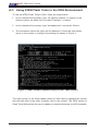
A-3 Using ATEN Flash Tools in the DOS Environment..........................................A-2
Firmware Updating via KCS Channels............................................................A-3
Dumping Firmware from the BMC via KCS channels.....................................A-4
A-4 Using ATEN Flash Tools in Windows/Linux ....................................................A-6
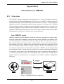
Appendix B Introduction to SMASH ...................................................... B-1
B-1 Overview..........................................................................................................B-1
How SMASH works..........................................................................................B-1
SMASH Compliance Information.....................................................................B-2
B-2 An Important Note to the User.........................................................................B-2
B-3 Using SMASH..................................................................................................B-3
B-4 Initiating the SMASH Protocol.........................................................................B-3
To Initiate SMASH Automatically.....................................................................B-3
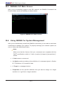
B-5 SMASH-CLP Main Screen...............................................................................B-4
B-6 Using SMASH for System Management..........................................................B-4
B-7 Definitions of Command Verbs........................................................................B-5
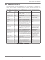
B-8 SMASH Commands.........................................................................................B-7
B-9 Standard Command Options...........................................................................B-8
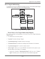
B-10 Target Addressing............................................................................................B-9
Terms Used in the Target Addressing Diagram...............................................B-9
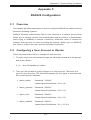
Appendix C RADIUS Configuration......................................................... C-1
C-1 Overview..........................................................................................................C-1
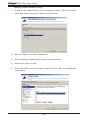
C-2 Configuring a User Account in Ubuntu............................................................C-1
C-3 Configuring Client Information in Ubuntu.........................................................C-2
C-4 Starting the RADIUS Server in Ubuntu............................................................C-2
C-5 Adding Roles in Windows................................................................................C-3
vii
SMT IPMI User's Guide
Notes
viii
Chapter 1: Introduction
Chapter 1
Introduction
1-1 Overview of the Nuvoton WPCM 450/ASpeed AST
2400 BMC Controller
The Nuvoton WPCM450/ASpeed AST 2400 Baseboard Management Controller
(BMC) supports PCIe-based 2D VGA Graphics cores, multi-media virtualization, and
Keyboard/Video/Mouse Redirection (KVMR). The WPCM450/AST2400 controller is
ideal for networking management.
The WPCM450/AST2400 interfaces with the host system via PCI connections to
communicate with the Graphics core. It supports USB 2.0 and 3.0 for remote KVM
emulation. It also provides LPC interface support to control Super IO functions. The
BMC is connected to the network via an external Ethernet PHY module or shared
NCSI connections.
The WPCM450/AST2400 communicates with onboard components via SMBus
interface, PECI (Platform Environment Control Interface) buses, and General Purpose IO ports.
WPCM450/AST2400 DDR2/DDR3 Memory Interface
The WPCM450/AST2400 controller supports DDR2/DDR3 memory with a speed of
up to 400MHz. The controller supports 128 MB of memory which is shared between
the BMC and onboard graphics card. For best signal integrity, the WPCM450/
AST2400 provides point-to-point connections.
WPCM450/AST2400 PCI System Interface
The WPCM450/AST2400 provides 32-bit, 33 MHz 3.3V PCI interface, which is compliant with PCI Local Bus Specification Rev. 3.0. The PCI system interface connects
to the onboard PCI Bridge and is used by the graphics controller.
1-1
SMT IPMI User's Guide
WPCM450 Block Diagram
The following diagram represents a typical system setup for the WPCM450 controller.
PROCESSOR
PCI-E
PECI
USB
2.0
USB
1.1
PCI
LPC
South Bridge
Wake-up & CTRL
RMII
Serial Port
WPCM450
RMII
VGA
SPI
Sensors
DDR2
1-2
Ethernet CTRL
Onboard LAN1
RS232
PHY
RJ45
Serial Port
RJ45
Dedicated LAN
NOR Flash
Chapter 1: Introduction
1-2 Supermicro IPMI Features
1. Remote KVM (graphics) console
2. Virtual Media and ISO images
3. Remote server power control
4. Remote Serial over LAN (text console)
5. Event Log support
6. Automatic Notification and Alerts (SNMP and email)
7. Hardware Monitoring
8. Overall health display on the main page
9. Out of band management through shared or dedicated LAN
10. Option to change LAN connection interface at Runtime
11. VLAN
12. RMCP & RMCP+ protocols supported
13. SMASH/CLP
14. Secure command line interface (SSH) and Telnet
15. WSMAN and WS-CIM
16. RADIUS authentication support
17. Secure browser interface (Secure socket layer - SSL support)
18. Lightweight Directory Access Protocol (LDAP) supported
19. DCMI 1.0 support
20. Backup and restore the configuration file
21. Factory defaults from web support
22. Video quality settings
23. Record video and play
24. Server data/information
25. Preview of the remote screen on the main page
26. Update Firmware through browser and OS
27. OS-independent
1-3
SMT IPMI User's Guide
1-3 Introduction to the IPMI Platform
The Intelligent Platform Management Interface (IPMI) provides remote access to
multiple users at different locations for networking. It also allows a system administrator to monitor system health and manage computer events remotely.
IPMI operates independently from the operating system. When used with an IPMI
Management utility installed on the motherboard, the WPCM450/AST2400 BMC
Controller will connect the South Bridge to other onboard components, providing
remote network interface via serial links. With the WPCM450/AST2400 controller
and the IPMI firmware built in, the Supermicro motherboard allows the user to access, monitor, diagnose, and manage a remote server via Console Redirection. It
also provides remote access to multiple users from different locations for system
maintenance and management.
1-4 Supported Motherboards
Please refer to the motherboard product page at www.supermicro.com to see if
your motherboard supports IPMI.
1-5 An Important Note to the User
The graphics shown in this user's guide were based on the latest information
available at the time of publishing of this guide. The IPMI screens shown on your
computer may or may not look exactly like the screen shown in this user's guide.
1-4
Chapter 2: Configuring BMC/IPMI Settings
Chapter 2
Configuring the IPMI Settings
With the Nuvoton WPCM450/ASpeed AST2400 BMC Controller and the IPMIView
firmware built in, Supermicro motherboards allow the user to access, monitor,
manage and interface with multiple systems in different remote locations. The
necessary firmware for accessing and configuring the IPMI settings are available
on Supermicro website at http://www.supermicro.com/products/nfo/ipmi.cfm. This
section provides detailed information on how to configure the IPMI settings.
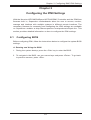
2-1 Configuring BIOS
Before configuring IPMI, follow the instructions below to configure the system BIOS
settings.
A. Entering and Using the BIOS
1. During the system bootup, press the <Del> key to enter the BIOS.
2. To navigate in the BIOS, use your arrow keys and press <Enter>. To go back
to previous screens, press <Esc>.
2-1
SMT IPMI User's Guide
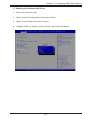
B. Enabling the COM port for SOL (IPMI)
1. Select the Advanced tab.
2. Select Serial Port Console Redirection and press <Enter>.
3. Highlight SOL/COM2 Console Redirection, press <Enter> and select
[Enabled].
2-2
Chapter 2: Configuring BMC/IPMI Settings
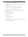
C. Enabling All Onboard USB Ports
1. Select the Advanced tab.
2. Select Chipset Configuration and press <Enter>.
3. Select South Bridge and press <Enter>.
4. Highlight USB 3.0 Support, press <Enter> and select [Enabled].
2-3
SMT IPMI User's Guide
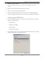
D. Configuring IP Address Using the BIOS
1. Select the IPMI tab.
2. Select BMC Network Configuration and press <Enter>.
3. Highlight Update IPMI LAN Configuration, press <Enter> and select [Yes].
4. Highlight Configuration Address Source and select [Static].
2-4
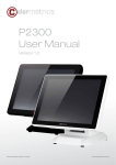
Chapter 2: Configuring BMC/IPMI Settings
5. Once the Configuration Address Source is set to [Static], the Station IP Address, Subnet Mask and Gateway IP Address fields should be 0.0.0.0, which
is activated for changing. Select each of the three items and enter the values.
Press <Enter> when finished.
2-5
SMT IPMI User's Guide
2-2 Configuring the IP/MAC Addresses for Remote
Servers
Note: The DHCP (Dynamic Host Configuration Protocol) is on by default.
To change the manufacturer default setting, please use the ipmicfg utility
or the BIOS Setup utility.
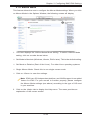
Using the IPMICFG Utility to Set the IP Addresses for
Remote Servers
1. Run the ipmicfg utility. You can get this from the Supermicro website at www.
supermicro.com or from the Supermicro ftp site at ftp://ftp.supermicro.com/
utility/IPMICFG/.
2. Follow the instructions given in the readme.txt file to configure Gateway IP/
Netmask IP addresses, enable/disable DHCP, and configure other IPMI settings.
IPMICFG Version 1.20.3 © 2014 Super Micro Computer, Inc.
Usage: IPMICFG Parameters
-m
Show IP and MAC
-m IP
Set IP (format: ###.###.###.###)
-a MAC
Set MAC (format: ##:##:##:##:##:##)
-k
Show Subnet Mask
-k Mask
Set Subnet Mask (format: ###.###.###.###)
-dhcp
Get the DHCP status
-dhcp on
Enable the DHCP
-dhcp off
Disable the DHCP
-g
Show Gateway IP
-g IP
Set Gateway IP (format: ###.###.###.###)
-garp on
Enable the Gratuitous ARP
-garp off
Disable the Gratuitous ARP
-fd
Reset to the factory default
-fdl
Reset IPMI to the factory default (CLEAN LAN)
-fde
Reset to the factory default (clear FRU and LAN)
-ver
Get Firmware revision
-vlan
Get VLAN status
-vlan on [VLANtag]
Enable the VLAN and set the VLAN tag.
If VLANtag is not given it uses previously saved value.
2-6
Chapter 2: Configuring BMC/IPMI Settings
-vlan off
Disable the VLAN
-raw
Send a RAW IPMI request and print response.
-fan
Get fan mode
-fan <mode>
Set fan mode
-nm nmsdr
Display NM SDR
-nm seltime
Get SEL time
-nm deviceid
Get ME device ID
-nm reset
Reboot ME
-nm reset2default
Force ME reset to default
-nm updatemode
Force ME to update mode
-nm selftest
Get self-test results
-nm listimagesinfo
List ME image information
-nm oemgetpower
OEN power command for ME
-nm oemgettemp
OEM temp. commance for ME
-nm pstate
Get max. allowed CPU P-state
-nm tstate
Get max. allowed CPU T-state
-nmcpumemtemp
Get CPU/memory temperature
-nm hostcpudata
Get host CPU data
-pminfo
Power-supply PMBus health
-psfruinfo
Power-supply FRU health
-psbbpinfo
Battery backup power status
-autodischarge
Set auto discharge by days
<module><day>
-discharge <module>
Manually discharge battery
-user list
List user privilege information
-user help
Show user privilege code
-user add <user id>
Add user
<username> <password> <privilege>
-user del <user id>
Delete user
-user level <user id>
Update user privilege
<privilege>
-user setpwd <user id>
<password>
Update user password
-conf upload <file>
Upload IPMI configuration from binary file
<option>
-conf download <file>
Download IPMI configuration to binary file
2-7
SMT IPMI User's Guide
-conf tupload <file>
Upload IPMI configuration from text file
<option>
-conf tdownload <file>
Download IPMI configuration to text file
-sdr
Show SDR records and reading
-sdr del <SDR ID>
Delete SDR record
-sdr ver [<V1> <V2>]
Get/Set SDR version (V1 V2 are BCD format)
-sel info
Show SEL info
-sel list
Show SEL records
-sel raw
Show SEL raw data
-sel del
Delete all SEL records
-fru info
Show FRU inventory area Info
-fru list
Show all FRU values
-fru help
Show help of FRU Write
-fru cthelp
Show chassis type code
-fru <Field>
Show FRU field value
-fru <Field> <Value>
Write FRU
-fru 1m
Update FRU product manufacturer from DMITable
-fru 1p
Update FRU product name from DMITable
-fru 1s
Update FRU product S/N from DMITable
-fru 2m
Update FRU board manufacturer from DMITable
-fru 2p
Update FRU board product name from DMITable
-fru 2s
Update FRU board S/N from DMITable(sdc.exe needed)
-fru 3s
Update FRU chassis S/N from DMITable
-fru backup <file>
Backup FRU to bin file
-fru restore <file>
Restore FRU from bin file
-fru tbackup <file>
Backup FRU to text file
-fru trestore <file>
Restore FRU from text file
-fru ver <V1> <V2>
Get/Set FRU version (V1, V2 are BCD format)
-fru dmi <$1> <$2>
$1 Product manufacturer name
$2 Product name
$3 Product part number
$4 Product version
$5 Product serial number
$6 Product asset tag
$7 Board manufacturing date/time
$8 Board manufacturer name
$9 Board product name
$10 Board part number
$11 Board serial number
$12 Chassis type
$13 Chassis part number
$14 Chassis serial number
<$3>
<$4>
<$5>
<$6>
<$7>
<$8>
<$9> <$10> <$11>
<$12> <$13> <$14>
2-8
Chapter 2: Configuring BMC/IPMI Settings
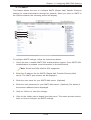
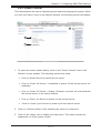
2-3 Connecting to the Remote Server
Using IPMIView to Connect to the Remote Server
1. Connect a LAN cable to the onboard LAN1 port or the dedicated IPMI LAN
port.
2. Choose a computer that is connected to the same network and open the
IPMIView utility.
3. Go to File>New>System. Enter the System Name, IP Address of LAN1 (or
the dedicated LAN, and the Description in the appropriate fields, and press
<Enter>.
4. Select the system from the IPMI Domain. Enter the Login ID and Password in
the appropriate fields to log in to the IPMIView utility.
Using the Browser to Connect to the Remote Server
1. Connect a LAN cable to the onboard LAN1 port or the IPMI LAN port.
2. Choose a computer that is connected to the same network and open the
browser.
3. Enter the IP address of each server that you want to connect to in the address bar of your browser.
4. Once the connection is made, the Login screen as shown on the next page
will display.
Notes:
1. The default network setting is "Failover", which will allow the IPMI to
connect to the network through a shared LAN port (onboard LAN Port 1 or
0) or through the IPMI Dedicated LAN Port. If the IPMI must be connected
through a specific port, please change the LAN configuration setting under
the Network Settings.
2. For IPMI to work properly, please enable all onboard USB ports and the
COM port designated for SOL (IPMI) on the motherboard. All USB ports
and the COM port for IPMI are enabled in the system BIOS by default.
The COM port for IPMI is marked with "*" in the BIOS. It is usually listed
as COM2 or COM3 in the BIOS. Refer to Section 2-1 Configuring BIOS
for more information.
2-9
SMT IPMI User's Guide
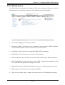
2-4 Accessing the Remote Server via Console
Redirection Using the Browser
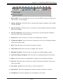
To Log In to the Remote Console
Once you are connected to the remote server via IPMI Console Redirection, the
following IPMI Login screen will display.
1. Enter your username in the Username box.
Note: The manufacturer default username and password are ADMIN/ADMIN.
Once you have logged into the BMC using the manufacturer default password,
be sure to change your password for security purpose.
2. Enter your password in the Password box and click on <Login>.
3. The home page will display as shown on the next page.
Note 1: To use the IPMIView utility for Console Redirection, please refer to the
IPMIView User's Guide for instructions.
Note 2: The Administrator account cannot be deleted.
2-10
Chapter 2: Configuring BMC/IPMI Settings
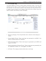
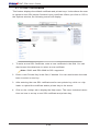
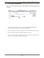
2.5 IPMI Main Screen
The IPMI Main screen displays the following information.
5
1
2
6
3
8
4
7
The IPMI Main screen displays system information, including the following:
1. The Menu bar: The menu bar on the top displays System Information, Server
Health, Configuration, Remote Control, Virtual Media, Maintenance, Miscellaneous, and Help. Click an item on the menu bar to access an IPMI feature
and configure its settings.
2. The System window: This window displays the System submenu items. Click
an item in this window to configure the following settings.
3. FRU Reading: This page details the FRU (Field Replaceable Unit) information. Click on "FRU Reading" to display this information.
4. Hardware Information: This page shows the hardware architecture. Click on
"Hardware Information" to display the following information:
•System
•Manufacturer
•Product Name
•Serial No.
2-11
SMT IPMI User's Guide
•BIOS
•Vendor
•Version
•Release
•CPU
•CPU1
•CPU2
•DIMM
•Shows the slots that are occupied by DIMM modules
(e.g. P1-DIMMA1, P2-DIMME1)
•Power Supply
•Upper Slot
•Lower Slot
5. Language Select: From the pull-down menu, select a language.
•English
•Japanese
6.
Summary: This field provides the following information:
•Firmware Revision
•Firmware Build Time
•BIOS Version
•BIOS Build Time
•IP Address
•BMC MAC Address
•System LAN MAC Address (all available LANs)
2-12
Chapter 2: Configuring BMC/IPMI Settings
•Remote Console Preview - a display of the remote system (the host machine) running at the specified IP address
7.
Power Control via IPMI: This field provides options for powering on and off
the host sytem.
•Power On: Click this button to power on the host system.
•Power Down: Click this button to power off the host system.
•Reset: Click this button to reset the host system.
8. Click on the <Help> tab to display the Help menu. The menu displays the
following information:
•Firmware Revision/Buiild Time
•BIOS Version/Build Time
•IP Address
•BMC/SystemMAC Address
•Preview Screen
•Launch Console: This feature allows the user to launch the remote console
by clicking a preview screen.
2-13
SMT IPMI User's Guide
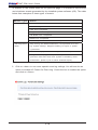
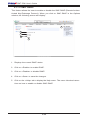
2.6 Server Health
This feature allows the user to set Server Health settings. When you click on Server
Health in the Options window, the following screen will display
1
2
1. This section shows data related to the server's health, such as sensor readings and the event logs.
•Sensor Readings: See readings from various sensors
•Event Log: See events written to the event log
2. Click on the <Help> tab to display the Help menu. The menu displays information relating to the server's health.
2-14
Chapter 2: Configuring BMC/IPMI Settings
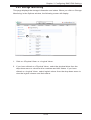
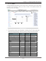
2.6.1 Sensor Readings
This page displays system sensor readings for the remote console. When you
click on Sensor Readings in the Options window, the following screen will display
4
3
5
8
1
2
6
7
1. From the pull-down menu, select a sensor type (category). The options
include the following.
•All Sensors
•Temperature Sensors
•Voltage Sensors
•Fan Sensors
•Power Supply
•Other Units-based Sensor
2. A sensor color that is displayed in front of an sensor indicates the status of
the sensor.
•Green: It indicates that the sensor reading is normal. The system functions
normally.
•Amber: There is an alert on the sensor reading. Attention is needed to ensure
that the system is functioning properly.
2-15
SMT IPMI User's Guide
•Red: One or more sensors have reached the critical state. Immediate action is
needed to resolve the problem.
•No Color: There is no sensor reading.
3. Name: This column displays the names of the sensors that are currently active in system monitoring, including system temperature, CPU temperature,
fan speeds, CPU core voltages, +3.3Vcc, and +12V voltage monitoring.
4. Status: This column indicates the status of each sensor reading.
5. Reading: This column indicates the reading of each sensor.
6. Refresh: Click this item to refresh the page.
7. Show Thresholds: Click this item to display senor thresholds.
8. Click on the <Help> tab to display the Help menu. The menu displays the
following information:
•An explanation of the green, amber, and red sensors.
•An explanation of each column on the page.
•The functions of each button on the page.
2-16
Chapter 2: Configuring BMC/IPMI Settings
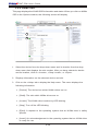
2.6.2 Event Log
This page displays a record of critical system monitoring events. The event log
indicates the time when a critical condition had occurred and when this condition
was resolved. You can choose a specific event category from the pull-down menu
to display events included in this category. When you click on Event Log in the
Options window, the following screen will display.
3
2
1
1. Event Log Category: From the pull-down menu, select an event category to
display.
•Sensor-Specific Events: These event logs are generated by the BMC if the
sensor's reading reaches the threshold.
•BIOS-Generated Events: These event logs are generated by the BIOS and
logged to the BMC.
•System Management Software Events: These events logs are generated by the
OS, application software, etc., and logged to the BMC.
•All Events: This category includes all the above event logs.
2-17
SMT IPMI User's Guide
In addition to the events listed on the previous page, it is normal to see boot-up
and shutdown events generated by the installed system software (OS). The table
below lists examples of these types of events.
Sensor Type
OS Boot
Event
A: boot completed
C: boot completed
PXE boot completed
Diagnostic boot completed
CD-ROM boot completed
ROM boot completed
Boot completed - boot device not specified
OS Stop/Shut-
Stop during OS load/initialization, Unexpected error dur-
down
ing system startup, Stopped waiting for input or power
cycle/reset
Run-time stop (a.k.a 'core dump', 'blue screen')
OS graceful stop (system powered up, but normal OS
operation has shut down and system is awaiting reset
pushbutton, power cycle or other external input)
2. Click on <here> to see more special event log settings. You will see the an
option to enable AC Power On Event Log. Check the box to enable the option
and click on <Save>.
2-18
Chapter 2: Configuring BMC/IPMI Settings
3. Click on the <Help> tab to display the Help menu. The menu displays information for the following features:
•[Sensor-Specific Events]
•[BIOS-Generated Events]
•[System Mangement Software Events]
•[All Events]
2-19
SMT IPMI User's Guide
2.6.3 Power Consumption
This page displays the Maximum, Minimum and Average power consumption in the
last hour, day and week. When you click on Power Consumption in the Options
window, the following screen will display
4
1
2
3
1. Estimate remaining BBP run time: Displays the battery backup power run
time.
2. The highest and lowest peak: Displays the highest and lowest peak of power
consumption.
3. Power consumption graph and history: Displays the average, minimum and
maximum power consumption of the past hour and week.
4. Click on the <Help> tab to display the Help menu. The menu displays the
following information:
•The estimated BBP run time.
•Power consumption for one hour, day, and week.
2-20
Chapter 2: Configuring BMC/IPMI Settings
2.6.4 Power Source
This page displays the power source information. When you click on Power Source
in the Options window, the following screen will display
4
1
2
3
1. BBP Setting: Displays the battery backup power settings. You can enable or
disable the graceful shutdown and specify the timeout value (in seconds).
2. Timeout Value for graceful shutdown: This feature allows you to enable or disable a graceful shutdown. Specify the timeout value in seconds.
3. Slot 2 Status: Displays the following information for the indicated slot:
•Status
•AC Input Voltage
•AC Input Current
•DC 12V OUtput Voltage
•DC 12VOUtput Current
•Temperature 1
2-21
SMT IPMI User's Guide
•Temperature 2
•Fan 1
•Fan 2
•DC 12V Output Power
•AC Input Power
•PWS Serial Number
4. Click on the <Help> tab to display the Help menu. The menu displays details
on the power source settings:
2-22
Chapter 2: Configuring BMC/IPMI Settings
2.6.5 Storage Monitoring
This page displays the storage information and status. When you click on Storage
Monitoring in the Options window, the following screen will display
1
2
1. Click on <Physical View> or <Logical View>.
2. If you have clicked on <Physical View>, select the physical drive from the
drop-down menu to view the drive numbers and their status. If you have
clicked on <Logical View>, select logical volume from the drop-down menu to
view the logical volumes and their status.
2-23
SMT IPMI User's Guide
2.6.6 NVMe SSD
This page displays the NVM3 SSD information and status. When you click on NVMe
SSD in the Options window, the following screen will display
3
1
2
1. Select the device from the drop-down menu and its location from the dropdown menu that displays the slot number. After you have selected a device
and its location, click on <Locate>, <Stop Locate>, or <Eject>.
2. Displays information on the selected device and slot.
3. Click on the <Help> tab to display the Help menu. The menu displays the
following information:
•[Device]: The device bus which NVMe drives are on.
•[Slot#]: The slot which NVMe drives are on.
•[Locate]: The NVMe drive location by LED blinking.
•[Stop]: Turn off the LED blinking.
•[Eject]: A request to the operating system that an NVMe drive is safely
ejected.
•[Insert]: An acknowledgement to the operating system that an NVMe drive
is ready for use.
2-24
Chapter 2: Configuring BMC/IPMI Settings
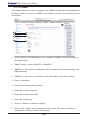
2.7 Configuration
This feature allows the user to configure various network settings. When you click
the Configuration on the menu bar, the following screen will display.
2
1
1. This section allows the user to configure the following settings.
•Alerts: Use this item to configure alert destination settings.
•Date & Time
•LDAP: Use this item to configure LDAP (Lightweight Directory Access Protocol) settings for authentication and access to the LDAP server.
•Active Directory: Use this item to configure the settings for authentication
and access to the Active Directory server.
•Radius: Use this item to configure the settings for authentication and access
to the Radius server.
•Mouse mode
•Network
•Dynamic DNS
2-25
SMT IPMI User's Guide
•SMTP
•SSL Certificate
•Users
•Port
•IP Access Control
•SNMP
•Fan Mode
•Web Session
2. Click on the <Help> tab to display the Help menu for the Configuration
screen.
2-26
Chapter 2: Configuring BMC/IPMI Settings
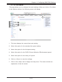
2.7.1 Alerts
This feature allows the user to configure Alert settings. When you click on Alerts in
the menu bar, the following screen will display.
5
1
2
3
4
To setup an alert or to modify an alert setting, do the following.
1. Click on <Alerts> to activate the alert submenu.
2. Click on <Modify> to configure or modify the settings of an alert.
3. Send Test Alert is used to check if the alerts have been set and sent out correctly.
4. Click on <Delete> to delete an alert.
5. Click on the <Help> tab to display the Help menu. This menu shows you how
to set up or modify an alert.
2-27
SMT IPMI User's Guide
To Setup an Alert
1
3
5
2
4
6
Follow the steps below to setup an alert.
1. Select Alerts from the window on the left. Highlight the alert and select Modify.
2. Select Event Severity.
3. Enter the destination IP address to use SNMP. For further guidance on typical
inquiries relating to SNMP, see the table on the next page.
2-28
Chapter 2: Configuring BMC/IPMI Settings
Item
Answer
SNMP version number
SNMP version 2.
MIB community name
A community name is not required since
SNMP version 2 only uses traps.
MIB file location
Go to http://www.supermicro.com/products/
nfo/IPMI.cfm and click on “IPMI MIB (SMT)”
(right-hand side of the page).
The IPMI item you need to configure so the SNMP manager
can receive the SNMP trap
The alert LAN destination address (see #4
under 2.4.1) must be set to the same IP in
as the SNMP manager.
Can I query for detailed infor- Detailed queries are not possible because
mation on the MIB "Event" trap event mapping is based only on sensor
items?
type, event type, and sensor offset.
A list of trap items generated for No standard list of event traps exist bemy platform
cause the PEF (Platform Event Filter) table
is OEM customizable.
4. Enter the email address to send the alert to, then configure the SMTP settings
(see section 2.8.10)
5. Enter the subject line of the alert.
6. Enter a message for the alert.
Click on <Save> to save the settings.
2-29
SMT IPMI User's Guide
2.7.2 Date and Time
This feature allows the user to configure the time and date settings for the host
server and the client computer. When you click on Time and Date in the Options
window, the following screen will display.
9
1
2
3
4
5
6
7
8
The user can either set the date & time setting manually or use the NTP Server
setting to set date & time. Follow the instructions below to set Date/Time settings.
Note: Time zone is enabled when NTP is selected. The options are UTC
-12:00 hr. ~ +12:00 hr.
1. Click on Date/Time on the left to set the date/time settings.
2. Select the time zone.
3. Check this item for NTP settings.
4. Enter the IP address for the primary NTP server.
5. Enter the IP address for the secondary NTP server.
6. Enter the date.
7. Enter the time in hh/mm/ss format.
8. Click on <Refresh> to change the date/time settings. Click on <Save> to save
the settings.
9. Click on the <Help> tab to display the Help menu. This menu includes instructions on how to the date and time.
2-30
Chapter 2: Configuring BMC/IPMI Settings
2.7.3 LDAP
This feature allows the user to configure the Light-Weight Directory Access Protocol
(LDAP) settings. When you click on LDAP in the Options window, the following
screen will display.
8
1
2
3
4
5
6
7
Follow the steps below to configure the LDAP settings.
1. Check the enable box to enable LDAP Authentication and LDAP Authentication over SSL support.
2. Enter a port number for the LDAP server.
3. Enter an IP Address for the LDAP server.
4. Enter a Bind Password for the LDAP server.
5. Enter a Bind DN value in the field. (The bind DN is the user or the LDAP
server that is permitted to do search in the LDAP directory within a defined
search base.)
6. Enter a SearchBase value in the field. (The SearchBase is the directory that
allows the external user to search data.)
7. Click on <Save> to save the settings.
8. Click on the <Help> tab to display the Help menu. This menu provides an
explanation of all the options displayed on the page.
2-31
SMT IPMI User's Guide
2.7.4 Active Directory
This page displays a list of role groups and their Group IDs, Group Names, Domains
and Network Privilege settings. When you click on Active Directory in the Options
window, the following screen will display.
1
2
3
5
4
1. Click on <HERE> to enable or configure the Active Directory server. See the
next page for enabling or configuring Active Directory instructions.
2. Select a group and click on <Add> to add a role group.
3. Select a group and click on <Modify> to modify a role group.
4. Select a group and click on <Delete> to delete a role group.
5. Click on the <Help> tab to display the Help menu. This menu provides instructions on how to add, modify, and delete a role group.
2-32
Chapter 2: Configuring BMC/IPMI Settings
Configuring the Active Directory Settings
This feature allows the user to configure the Advanced Active Directory settings.
When you click Here on the screen shown on the previous page, the following
screen will display.
1
2
3
4
5
6
7
1. Check the <Enable> box to enable Active Directory authentication support.
Then, Enter the values in the fields below.
2. Enter User Domain Name in the field.
3. Enter Time Out value in the field to set the time limit for a user to stay
logging-in.
4. Enter <Controller Server Address1>.
5. Enter <Controller Server Address2>.
6. Enter <Controller Server Address3>.
7. Click on <Save> to save the settings.
2-33
SMT IPMI User's Guide
2.7.5 RADIUS
This feature allows the user to configure Radius Option settings. When you click
on Radius in the Options Window, the following screen will display.
6
1
2
3
4
5
1. Check the <Enable> box to enable Radius support. Enter the information in
the fields below to configure Radius settings.
2. Enter the port number for the Radius server.
3. Enter the IP address of the Radius server.
4. Enter a secret (password) for the user to access the Radius server.
5. Click on <Save> to save the settings.
6. Click on the <Help> tab to display the Help menu. The menu includes instructions on how to configure the RADIUS settings.
2-34
Chapter 2: Configuring BMC/IPMI Settings
2.7.6 Mouse Mode
This feature allows the user to configure the Mouse Mode settings. When you click
on Mouse Mode in the Options Window, the following screen will display.
2
1
1. This item displays the current Mouse Mode setting. To select a Mouse Mode
setting, click on a mode shown below.
•Set Mode to Absolute (Windows, Ubuntu, RH6.x later). This is the default setting.
•Set Mode to Relative (Rest of the Linux). For other Linux operating systems.
•Single Mouse Mode: Check this to use single mouse mode.
•Click on <Save> to save the settings.
Note: IPMI is an OS-independent platform, and IKVM support is an added
feature for IPMI. For your mouse to function properly, please configure
the Mouse Mode settings (see above) according to the type of OS used
in your machine.
2. Click on the <Help> tab to display the Help menu. The menu provides an
explanation of the mouse modes.
2-35
SMT IPMI User's Guide
2.7.7 Network
This feature allows you to configure the network settings. When you click on Network
in the Options Window, the following screen will display.
8
1
2
3
4
5
6
7
To configure Network settings, follow the instructions below.
1. Select Obtain an IP automatically (use DHCP) or Use the following IP address
to manually configure one.
2. If you select Use the following IP address, enter information into the following
IPv4 Setting fields:
•IP address
•Subnet Mask
•Gateway
•DNS Server IP
3. To set the IP address using the IPv6 format, enter an address in the field.
Enter a DNS Server IP and DUID (unit ID) in the boxes.
2-36
Chapter 2: Configuring BMC/IPMI Settings
4. Check this box to enable Virtual LAN support and enter the VLAN ID in the
field.
5. LAN Interface: This feature allows the user to select the port to be used for
IPMI out-of-band communication.
•The default setting is Failover, which will allow IPMI to be connected from either
the shared LAN port (LAN1/0) or the dedicated IPMI LAN port. Precedence is
given to the Dedicated LAN port over the shared LAN port.
•Select <Dedicate> for IPMI to connect through the IPMI Dedicated LAN port
at all time.
•Select <Share> for IPMI to connect through the LAN port on the board.
6. RMCP Port: This feature allows the user to select the desired RMCP (Remote
Management Control Protocol) port. The default port is 623.
7. Click on <Save> to save the settings.
8. Click on the <Help> tab to display the Help menu. The menu inlcudes instructions on how to configure the Network settings.
2-37
SMT IPMI User's Guide
2.7.8 Dynamic DNS
This feature allows you to configure DNS (Dynamic Name System) settings. When
you click on Dynamic DNS in the Options Window, the following screen will display.
7
1
2
3
4
5
6
1. Click on <Dynamic Update Enable> to enable DNS support. Click on <Dynamic Update Disable> to disable Dynamic DNS update support. (Default:
Disable)
2. Enter the IP address of your Dynamic DNS (Domain Name System) server.
3. Enter the name of the BMC (Baseboard Management Controller) Host Server.
4. Check the box to enable TSIG Authentication support, and browse the files to
select the TSIG.key file. (This item is optional.)
5. Click on <Browse> to locate the TSIG.private file. (This item is optional.)
6. Click on <Save> to save the information you have entered.
7. Click on the <Help> tab to display the Help menu. The menu inlcudes instructions on how to configure the Dynamic DNS settings.
2-38
Chapter 2: Configuring BMC/IPMI Settings
2.7.9 SMTP
This feature allows the user to configure SMTP (Simple Mail Transfer Protocol)
settings for email transmission through the network. When you click on SMTP in
the Options window, the following screen will display.
6
1
2
3
4
5
To configure SMTP settings, follow the instructions below.
1. Check the box to enable SMTP SSL Authentication support. Once SMTP SSL
Authentication is enabled, enter information in the fields below.
Note: SHA2 and RSA 2048 bit SSL supported.
2. Enter the IP address for the SMTP (Simple Mail Transfer Protocol) Mail
server. The SMTP port number will be displayed.
3. Enter the user name for your SMTP Mail server. (Optional)
4. Enter the user password for your SMTP Mail server. (Optional) The status of
the sender's address will be displayed.
5. Click on <Save> to save the settings.
6. Click on the <Help> tab to display the Help menu. The menu inlcudes instructions on how to configure the SMTP settings.
2-39
SMT IPMI User's Guide
2.7.10 SSL Certification
This feature displays the default certificate and private keys. It also allows the user
to upload a new SSL (secure Sockets Layer) certificate. When you click on SSL in
the Options window, the following screen will display.
4
1
2
3
1. To enter a new SSL Certificate, enter a new certificate in the field. You can
also browse the data base to select a new certificate.
Note: SHA2 and RSA 2048 bit SSL supported.
2. Enter a new Private Key in the field, if desired. You can also browse the data
base to select a new key.
3. After entering the new SSL certificate and/or new private key, ckick on <Upload> to upload the certificate and/or private key to the server.
4. Click on the <Help> tab to display the Help menu. The menu includes instructions on how to set up a new SSL certificate and private key.
2-40
Chapter 2: Configuring BMC/IPMI Settings
2.7.11 Users
This page displays information on the current users. It also allows you to add, delete
or modify user information. When you click on Users in the Options window, the
following screen will display.
6
2
1
3
4
5
1. This item lists current user information, including User ID, User name and
Network Privilege settings. Network privilege settings are shown below.
Function System Information User Operator Administrator
Full Access Full Access Full Access Chassis Locator Control FRU Reading Sensor Readings Event Log Alert LDAP Mouse Mode Network Remote Session SMTP SSL Users Event Action Power Control KVM F/W Update SDR Update Logout View Only Full Access Full Access View Only No No No No No No No No No View Only View Only View Only View Only Full Access 2-41
Full Access
Full Access
Full Access
Full Access
View Only View Only Full Access
View Only View Only View Only View Only View Only View Only Full Access
Full Access
View Only View Only Full Access
Full Access Full Access Full Access Full Access Full Access Full Access Full Access Full Access Full Access Full Access Full Access Full Access Full Access Full Access Full Access Full Access Full Access Full Access SMT IPMI User's Guide
2. This item displays the number of the users that are set up for the network.
The maximum of 10 user profiles can be made.
3. To add a new user to the network, click on <Add User>. When prompted,
select an empty slot from the users list to add an user.
4. To modify the information or the status of a user, click on <Modify User>.
When prompted, select a user from the users list to modify the user information.
5. To delete a user from the network, click on <Delete User>. When prompted,
select a user from the users list to delete it from the list.
6. Click on the <Help> tab to display the Help menu. The menu displays an
explanation of the columns displayed on the page and how to add, modify,
and delete a user.
2-42
Chapter 2: Configuring BMC/IPMI Settings
2.7.12 Port
This page allows you to configure port settings. When you click on Port in the Options window, the following screen will display.
10
1
2
3
4
5
6
7
9
8
Check the box next to the port to configure the settings. Uncheck the box to disable the port.
1. Web port: Enter the web port number.
2. Web SSL port: Enter the Web SSL port number.
3. IKVM server port: Enter the IKVM port number.
4. Virtual media port: Enter the virtual media port number.
5. SSH port: Enter the SSH (Secure Shell) port number
6. Wsman port: Enter the WS-Management port number.
7. SNMP port: Enter the Simple Network Management Protocol port number.
8. SSL Redirection: Check the box to allow the IPMI webUI to redirect http to
https automatically.
9. Click on <Save> to save the settings.
10.Click on the <Help> tab to display the Help menu. The menu inlcudes port
setting information.
2-43
SMT IPMI User's Guide
2.7.13 IP Access Control
This page displays an IP Access Control table, which will allow you to add, modify
and delete an IP Access rule, an IP Address/Mask setting or an IP access policy.
6
1
5
2
3
4
1. Check this box to configure IP Access Control settings. When prompted, "Do
you want to enable IP access control," click on <OK>.
2. Rule Number: This column lists the number of IP Access Control rules.
3. IP Address/Mask: This column displays IP Address/Mask settings.
4. Policy: This column displays the status of an IP Access policy.
5. Number of Access Rules: This displays the maximum number of IP Access
rules you can set for the system.
6. Click on the <Help> tab to display the Help menu. The menu inlcudes an
explanation of all the columns displayed on the page.
2-44
Chapter 2: Configuring BMC/IPMI Settings
Modifying IP Access Rules
When you select an item and click on Modify, the Add Rule submenu will display
as shown below.
1
2
To modify a rule, enter the information needed for the following items:
1. IP Address/Mask: This item allows you to grant access to a specific IP address or a range of IP addresses. For example, if you wanted to specify a
range of IP addresses from 192.168.0.1 to 192.168.0.126, you would enter
192.168.0.1/25.
2. Policy: Select <Accept> to allow access for the IP address(es) entered above.
Select Drop to deny access.
2-45
SMT IPMI User's Guide
2.7.14 SNMP
This feature allows the user to configure the SNMP (Simple Network Management
Protocol). When you click on SNMP in the Options window, the following screen
will display.
6
1
2
3
4
5
1. Check the box to enable SNMP. Once SNMP is enabled, enter information in
the fields below.
2. SNMP Version: Select SNMPV2 or SNMPV3
3. SNMPV2: If this options is selected, enter a password for ROCommunity and
RWCommunity.
4. SNMPV3: If this option is selected, enter information in the fields below:
•Enter a username
•Select the Authentication Protocol
•Select the Private Protocol
•Enter the Authentication Key
•Enter the Private key
5. Click on <Save> to save the settings.
6. Click on the <Help> tab to display the Help menu. The menu includes an
explanation of all the options on this page.
2-46
Chapter 2: Configuring BMC/IPMI Settings
2.7.15 Fan Mode
This page allows you to configure fan mode settings. When you click on Fan Mode
in the Options window, the following screen will display.
7
1
2
3
4
5
6
1. This item displays the current fan mode setting.
2. Select this option for the standard fan speed setting.
3. Select this option for the full speed setting.
4. Select this option for the PUE2 (Power Utilization Effectiveness) speed.
5. Select this option for the Heavy IO speed.
6. Click on <Save> to save the settings.
7. Click on the <Help> tab to display the Help menu. The menu includes an
explanation of the fan modes.
2-47
SMT IPMI User's Guide
2.7.16 Web Session
This page allows you to configure web session parameters. When you click on Web
Session in the Options window, the following screen will display.
3
1
2
1. Enter the session timeout value. Values are in minutes and range from 1-30.
2. Click on <Save> to save the settings.
3. Click on the <Help> tab to display the Help menu. The menu defines the web
session parameters.
2-48
Chapter 2: Configuring BMC/IPMI Settings
2.8 Remote Control
This section allows the user to carry out activities and perform operations on a
remote server via remote access. When you click on Remote Control in the Options
window, the following screen will display.
4
1
2
3
1. Click on Console Redirection to launch Console Redirection and configure
the settings of the remote server. For more details on Console Redirection,
please refer to "Launching Console Redirection" on the next page.
2. Click on Power Control to display and configure the power settings of the
remote console, including the following settings.
•Reset Server
•Power Off Server-Immediate
•Power Off Server-Orderly Shutdown
•Power On Server
•Power Cycle Server
Once you have clicked the desired power setting, click on "Perform Action" to
change the power setting of the server.
3. Click on Launch SOL to launch SOL (Serial Over LAN) console and manage
the remote server.
4. Click on <Help> to display the Help menu for the Remote Control page.
2-49
SMT IPMI User's Guide
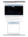
2.8.1 Launch Console Redirection
This feature allows you to launch Console Redirection via IKVM (keyboard, video/
monitor, mouse) support. When you click on Console Redirection in the Options
window, the following screen will display.
4
1
2
3
1. Click <Launch Console> on the Console Redirection screen to launch the
remote console via Java (for the Internet Explorer). You need to have Java
installed in your system to launch the console.
2. A dialog box will display to indicate that Java is launching
3. Click on <Run> to launch the remote console. The main screen like the one
below will appear. Note that your screen may not look exactly like the one
below.
4. Click on <Help> to display the Help menu for the Console Redirection page.
2-50
Chapter 2: Configuring BMC/IPMI Settings
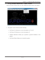
2.8.1a Console Redirection - Virtual Device
This feature allows you to configure virtual device settings for your console redirection.
1
2
3
1. Click on Virtual Media to configure virtual device settings of a server at a
remote site via Console Redirection.
2. Click on Virtual Settings to select a device you want to connect to the remote
server as a virtual device.
3. Click on Virtual Keyboard to launch the virtual keyboard.
2-51
SMT IPMI User's Guide
Virtual Storage
When you click on Virtual Storage as described on the previous page, the following screen will appear. You are able to use up to three devices for virtual storage..
1
4
3
2
5
1. Select the logical drive type from the dropdown menu. The options are as
follows:
•Upload IMA: Select to browse for and upload an IMA file.
•ISO File: Select to browse for and upload an ISO file.
•Web ISO: Select to mount a Web ISO. The file will be mounted from the web
interface. To specify the file location, set the image path on the CD-ROM Image page in the IPMI.
•C: SATA HD: Select to mount from the local computer you are using to ac- cess
the IPMI.
2. Click on <Plug in> to mount the selected drive.
3. Click on <Plug out> to unmount the selected drive.
4. Click on <Refresh> to refresh the connection status.
5. Click on <OK> to save the changes and exit the window.
2-52
Chapter 2: Configuring BMC/IPMI Settings
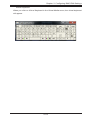
Virtual Keyboard
When you click on Virtual Keyboard in the Virtual Media menu, the virtual keyboard
will appear.
2-53
SMT IPMI User's Guide
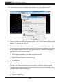
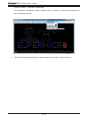
2.8.1b Console Redirection - Record
This feature allows you to record media displays for your console redirection.
1
2
3
4
1. Click on Start from the Record menu to start recording. The window shown
above will appear.
2. Then select the location to save the recording.
3. Enter a file name
4. Click on <Save> to save the settings and begin recording or click on <Cancel> to exit the window without recording. The recording process will continue
until you click on Stop under the Record menu.
2-54
Chapter 2: Configuring BMC/IPMI Settings
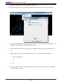
2.8.1c Console Redirection - Macro
This feature allows you to configure Macro settings for your console redirection.
1
1. Click on Macro to configure the Macro settings for your remote server. The
fea- tures include the following:
•Hold Right Alt Key: This item performs the same function as holding down the
right <Alt> key.
•Hold Left Alt Key: This item performs the same function as holding down the
left <Alt> key.
•Right Windows Key: This item performs the same function as you pressing the
right <Windows> key. Select Hold Down or Press and Release.
•Left Windows Key: This item performs the same function as pressing the left
<Windows> key. Select Hold Down or Press and Release.
•Macro: Click this item to activate a pull-down submenu. The Macro submenu
includes the following items:
•Ctrl+Alt+Del
•Alt+Tab
•Alt+Esc
2-55
SMT IPMI User's Guide
•Ctrl+Esc
•Alt+Space
•Alt+Enter
•Alt+Hyphen
•Alt+F4
•Alt+PrntScrn
•PrntScrn
•F1
•Alt+F1
•Pause
2-56
Chapter 2: Configuring BMC/IPMI Settings
2.8.1d Console Redirection - Options
This feature allows you to configure Options settings for your console redirection.
1
1. Click on Options to activate the pull-down emnu to configure options settings.
The options menu allows you to configure the following settines:
•HotKey
•Preference
•Full-Screen Mode
•OSD UI Style
•Keyboard Mouse Hotplug
2-57
SMT IPMI User's Guide
Options - Hotkey Settings
This feature allows you to configure the hotkey settings for your console redirection.
1
3
5
2
4
6
7
1. To assign a hotkey for an action, click on Hotkey Settings under the Options
menu. A Hotkey Settings window will appear.
2. Click on <Start>
3. Enter the hotkey of your choice. It can be a single word or a combination.
4. Click on <Stop>
5. Select an item fron the action list.
6. Click on <Assign>
7. Click on <Close> to exit the window.
2-58
Chapter 2: Configuring BMC/IPMI Settings
Options - Preference (Display)
This feature allows you to configure video recording settings for your remote console.
2
3
4
5
6
1. Click on Preference under the Options menu. The Preference settings box will
display. The first tab is Display.
2. The Recording Time section refers to video recording. If you want to automatically stop recoring after a preset time, check the box, then input the number
of minutes that should pass before the recording should automatically stop.
3. Use the slider on the Display Scale to set the appropriate scale setting for
your display from Low (25) to High (100).
4. You can change the compression options under the Compression section.
5. You can adjust the image quality settings in accordance with varying degrees
of network traffic. To ensure the best image quality, select High for heavier
network traffic connections; select Low for lighter network traffic.
6. Click on <OK> to save the new setings or click on <Cancel> to exit the Preference win- dow without saving.
2-59
SMT IPMI User's Guide
Options - Preference (Input)
This feature allows you to configure input settings for your remote console.
2
3
4
5
1. Click on Preference under the Options menu. The Preference settings box will
display. The second tab is Input.
2. Check the Enable Mouse Input box to enable mouse support so that you can
use the mouse as an input device. Once mouse support is enabled, you need
to set a proper mouse mode for your remote console. Check the corresponding radio button from the list below.
•Select Absolute Mode if you have
the Windows OS
•Select Relative Mouse for the Linux OS.
•Single Mouse
3. Check the Enable Keyboard Input box to enable keyboard support so that
you can use a soft keyboard as an input device. From the Keyboard layout
pull-down menu, select the right language setting for your soft keyboard. The
language options are the following:
•English
•Chinese (traditional)
2-60
Chapter 2: Configuring BMC/IPMI Settings
•Japanese
•Germany
•French
•Spanish
•Korean
•Italian
•United Kingdom
•Swiss
4. To timeout repeated keystrokes, check the Repeat Key Timeout box, and use
the slider on the scale to select the appropriate timeout settings for repeat
keystrokes from 0ms to 1000ms (microseconds).
5. Click on <Save> to save the new settings or click on <Cancel> to exit the
Preference window without saving.
2-61
SMT IPMI User's Guide
Options - Preference (Language Setting)
This feature allows you to configure language settings for your remote console.
2
3
1. Click on Preference under the Options menu. The Preference settings box will
display. The third tab is Language Setting.
2. From the pull-down menu, select the language you want to use for your
remote console. The language options are the following:
•English
•Japanese
•German
•French
•Spanish
•Korean
•Italian
3. Click on <OK> to save the changes and exit the window or click on <Cancel>
to exit without saving.
2-62
Chapter 2: Configuring BMC/IPMI Settings
Options - Preference (Window)
This feature allows you to configure language settings for your remote console.
2
3
1. Click on Preference under the Options menu. The Preference settings box will
display. The fourth tab is Window.
2. Check Auto-resize window to reset the size of your display window.
3. Click on <OK> to save the change and exit the window or click on <Cancel>
to exit without saving.
2-63
SMT IPMI User's Guide
Options - Preference (Video Stream Control)
This feature allows you to configure window settings for your remote console.
2
3
4
1. Click on Preference under the Options menu. The Preference settings box will
display. The last tab is Video Stream Control.
2. Check the Enable Flow Control box to enable support for video stream control.
3. Select the speed from the pull-down menu. The options are as follows:
•256K Cable/DSL
•T1
•T2
4. Click on <OK> to save the change and exit the window or click on <Cancel>
to exit without saving.
2-64
Chapter 2: Configuring BMC/IPMI Settings
Options - Full Screen Mode
This feature allows you to configure window settings for your remote console.
1
1. Click on Full Screen Mode under the Options menu.
2. To leave the full-screen display, click on Leave Full-Screen Mode under the
Op- tions menu.
2-65
SMT IPMI User's Guide
Options - OSD UI Style
This feature allows you to configure OSD (On-Screen Display) UI (User Interface)
style settings for your remote console.
1
1. Click on OSD UI Style under the Options menu.
2. A gray box with shortcut icons will appear. They are shortcuts to the main
features provided by the firmware for your console redirection. Click on an
icon to activate its function. See the next page for the list of icons and their
functions.
2
2-66
Chapter 2: Configuring BMC/IPMI Settings
1
2
3
4
5
6
7
8
9
10
11
12
13
14
15
1. Move OSD: Click and drag this icon to move the OSD UI pop-up screen to a
new location on the display
2. Hotkey Settings: Click this icon to access the Hotkeys submenu and configure the settings.
3. Virtual Storage: Click this item to access the Virtual Media submenu andconfigure the settings.
4. Virtual Keyboard: Click this item to access the Virtual Keyboard submenu
and use your virtual (soft) keyboard.
5. Preference: Click this item to access the Preferences window.
6. Full-Screen Mode: Click this item to change the size of your display window
to the full screen mode.
7. Exit: Click this item to exit from the remote console.
8. Show User List: Click this item to display the user list.
9. Menubar UI Style: Click this item to change the toolbar display format.
10.Keyboard Mouse Hotplug: Click this item to hotplug keyboard and mouse.
11. Macro: Click this item to enable Macro support and use Macro features.
12.Record: Click this item to access the Video Recording submenu and to use
video recording.
13.Set power on-off: Click this item to turn the system off.
14.Resolution: This item displays the remote console resolution in pixels.
15.IP Address: This item displays the IP address of the IPMI.
2-67
SMT IPMI User's Guide
Options - Keyboard Mouse Hotplug
This feature allows you to enable keyboard/mouse hotplug support for your remote
console.
1
1. Click on Keyboard Mouse Hotplug under the Options menu.
2-68
Chapter 2: Configuring BMC/IPMI Settings
2.8.1e Console Redirection - User List
This feature allows you to access the user list.
1
1. Click on Show User List under the Options to show the user list. A pop-up
window will appear and show the following information:
•Session ID: This item displays the current session ID number.
•User Name: This item displays the name of each user.
•IP Address: This item displays the IP address of the client server.
2-69
SMT IPMI User's Guide
2.8.1f Console Redirection - Capture
This feature allows you to capture the screen displayed on your remote console.
1
1. Click on Full screen view under the Capture menu.
2-70
Chapter 2: Configuring BMC/IPMI Settings
2.8.1g Console Redirection - Power Control
Under the Power Control menu, you can manage the power state of the system.
1
1. The power control features are the following:
•Set Power On: Allows you to turn the system on if it is off.
•Set Power Off: Allows you to turn the system off.
•Software Shutdown: Allows you to perform a graceful shutdown of the
system.
•Set Power Reset: Allows you to reset the system.
2-71
SMT IPMI User's Guide
Power Control - Set Power On
The Set Power On option allows you to power on the system if the system is off.
1
1. Click the Set Power On option under the Power Control menu.
2-72
Chapter 2: Configuring BMC/IPMI Settings
Power Control - Set Power Off
The Set Power On option allows you to power off the system if the system is on.
1
1. Click the Set Power Off option under the Power Control menu.
2-73
SMT IPMI User's Guide
Power Control - Software Shutdown
The Software Shutdown option allows you to perform a graceful shutdown of
the operating system.
1
1. Click the Software Shutdown option under the Power Control menu.
2-74
Chapter 2: Configuring BMC/IPMI Settings
Power Control - Set Power Reset
The Set Power On option allows you to reset the system.
1
1. Click the Set Power Reset option under the Power Control menu.
2-75
SMT IPMI User's Guide
2.8.1h Console Redirection - Exit
Under the Power Control menu, you can manage the power state of the system.
1
2
1. To exit the Console Redirection, click on Exit under the Exit menu.
2. Click on <Yes> in the Exit dialog box to exit.
2-76
Chapter 2: Configuring BMC/IPMI Settings
2.8.2 Power Control
This feature allows the user to check the power state and manage the system. When
you click on Power Control in the Options window, the following screen will display.
3
1
2
1. To enter the screen shown above, click on the "Power Control" item in the
Remote Control sidebar. The following options are listed:
•Click on Reset Server to reset the host server.
•Click on Power Off Server - Immediate to power off the remote server immediately.
•Click on Power Off Server - Orderly Shutdown to power off and shutdown
the remote server in an orderly fashion.
•Click on Power On Server to power on the remote server.
•Click on Power Cycle Server to power cycle the remote server.
2. Click on <Perform Action> after choosing an option to commence
3. Click on the <Help> tab to display the Help menu. The menu includes an
explanation of all the power modes.
2-77
SMT IPMI User's Guide
2.8.2 Launch SOL
This feature allows you to launch the remote console by using SOL (Serial over
LAN). This feature provides serial port connections over LAN to allow the user to
access a host server via console redirection. It also allows a system administrator
to monitor and manage a server from a remote site.
4
1
2
3
1. To enter the screen shown above, click on Launch SOL in the left coloumn.
2. Click on the <Launch SOL> button to launch SOL.
3. In the dialog box that asks "Do you want to run this application?', click on
<Run>. The SOL Viewer screen will appear as shown on the next page.
4. Click on the <Help> tab to display the Help menu. The menu inludes an
explanation of the SOL Console.
2-78
Chapter 2: Configuring BMC/IPMI Settings
1
2
3
1. You can select a baud rate (bps) from the pull-down menu as your SOL transfer rate. The options are listed below. Make sure that the baud rate selected
here matches the baud rate set in the BIOS.
•9600 bps (bits per second)
•9200 bps
•38400 bps
•57600 bps
•115200 bps
2. Once you have selected the baud rate, click on <Start> to start the session.
Once you have started the session, you can input SOL commands through
the command-line interface.
3. Click on <Stop> to stop the SOL connection.
2-79
SMT IPMI User's Guide
2.9 Virtual Media
This feature allows you to upload and share images via the BMC (Baseboard
Management Controller). These images will be emulated to the host server as USB
applications. When you click on Virtual Media in the Options window, the following
screen will display.
1
2
1. This section shows information related to virtual media, such as Floppy Disk
and CD-ROM Image.
•Floppy Disk: Upload a binary image with a maximum size of 1.44MB. This image
will be emulated to the host as a USB device.
•CD-ROM Image: Share a CD-ROM image over Windows Share with a maximum
size of 4.7GB. This image will be emulated to the host as a USB device.
2. Click on the <Help> tab to display the Help menu for the Virtual Media page.
2-80
Chapter 2: Configuring BMC/IPMI Settings
2.9.1 Floppy Disk
This feature allows you to configure Floppy Disk image files for sharing. When you
click on Floppy Disk in the Options window, the following screen will display.
5
1
2
3
4
1. Dislpays a list of devices and their status (e.g. Device 1, Device 2, Device 3).
2. Click on <Refresh Status> to refresh the Floppy disk.
3. Click on <Browse> to select an image file from a specified location for your
console redirection.
4. After you have selected your image file, click on <Upload> to upload your
image file to the server.
5. Click on the <Help> tab to display the Help menu. The menu explains the
function of each button on the page.
2-81
SMT IPMI User's Guide
2.9.2 CD-ROM Image
This feature allows you to configure CD-ROM image files for sharing. When you
click on CD-ROM Image in the Options window, the following screen will display.
9
1
2
3
4
5
6
7
8
1. Dislpays a list of devices and their status (e.g. Device 1, Device 2, Device 3).
2. Click on <Refresh Status> to refresh USB Floppy/Flash and CD ROM/ISO
devices.
3. Enter the Share Host server for your console redirection.
4. In the Path to Image field, enter the path to the CD-ROM image file for sharing.
5. In the Users (Optional) field, specify the users that have access to the CDROM image files. (This item is optional).
6. In the Password (Optional) field, enter your user password. (Optional.)
7. To mount an image file, click on <Save> and then <Mount>.
8. To unmount an image file, click on <Unmount> and then <Save>.
9. Click on the <Help> tab to display the Help menu. The menu inlcudes instructions on how to share a CD-ROM image.
2-82
Chapter 2: Configuring BMC/IPMI Settings
2.10 Maintenance
Use this feature to manage and configure IPMI device settings. When you click on
Maintenance in the Options window, the following screen will display.
2
1
1. This screen displays the following items:
•Firmware Update: Click this item to update the remote server's BMC firmware.
The Firmware Update screen is shown in the next section.
•Unit Reset: Click this item to reboot the BMC (IPMI) controller.
•IKVM Reset: Click this item to reset the IKVM setting.
•Factory Default: Click this item to restore IPMI to the factory default settings.
•IPMI Configuration: Click this item to save IPMI configuration settings to a file
or to load IPMI configuration settings from a file.
•System Event Log: Click this this item to turn on or off the system event log.
•BIOS Update: Click this item to update the BIOS.
2. Click on the <Help> tab to display the Help menu for the Maintenance page.
2-83
SMT IPMI User's Guide
2.10.1 Firmware Update
Use this feature to update the IPMI firmware. When you click on Firmware Update
in the Options window, the following screen will display.
5
1
2
3
4
To update IPMI Firmware, follow the instructions below.
1. Click on <Enter Update Mode>.
2. A dialog box will a. It will ask: "Do you want to enter update mode?" Click on
<OK> to proceed with the update.
3. Click on <OK> to update your IPMI firmware. After you click <OK> to update
the firmware, the Firmware Upload screen will display as shown on the next
page.
4. Click on <Cancel> to cancel firmware updates.
5. Click on the <Help> tab to display the Help menu. The menu includes instructions on how to update the firmware.
Warning: Once the server is in the firmware update mode, the device will
reset, and the server will reboot even if you cancel the firmware update.
2-84
Chapter 2: Configuring BMC/IPMI Settings
After you click on <OK> to update the IPMI Firmware, the following Firmware Upload
screen will display as shown below.
6
7
8
6. Enter the name of the firmware you wish to upload. You can also select a
firmware specified location by clicking on <Browse>.
7. Click on <Upload Firmware> to upload the selected firmware to the host
server.
Warning: To properly update your firmware, do not interrupt the process.
The system will reboot after the firmware update is complete.
8. Click on <Cancel> to abort firmware uploading.
2-85
SMT IPMI User's Guide
2.10.2 Unit Reset
Use this feature to reset the IPMI device. When you click on Unit Reset in the Options window, the following screen will display.
2
1
1. Click on <Reset> to reset the IPMI device.
2. Click on the <Help> tab to display the Help menu for the Unit Reset page.
2-86
Chapter 2: Configuring BMC/IPMI Settings
2.10.3 IKVM Reset
This feature allows you to reset IKVM. It will reset virtual media, IKVM keyboard
and mouse. When you click on IKVM Reset in the Options window, the following
screen will display.
2
1
1. Click on <Reset> to reset virtual media, IKVM keyboard and mouse.
2. Click on the <Help> tab to display the Help menu for the IKVM Reset page.
2-87
SMT IPMI User's Guide
2.10.4 Factory Default
This feature allows the user to restore IPMI to factory default settings. When you
click on Factory Default in the Options window, the following screen will display.
2
1
1. Click on <Restore> to reset the IPMI to factory default settings. The IPMI connection will reset.
2. Click on the <Help> tab to display the Help menu for the Factory Default
page.
2-88
Chapter 2: Configuring BMC/IPMI Settings
2.10.5 IPMI Configuration
This feature allows the user to save IPMI configuration settings and restore it.
When you click on IPMI Configuration in the Options window, the following screen
will display.
4
1
2
3
1. Click on <Save> to save the current IPMI configuration.
2. Click on <Browse> to select a configuration from specified location to reload.
3. Click on <Reload> to save the IPMI Configuration settings.
4. Click on the <Help> tab to display the Help menu. The menu includes instructions on how to configure the IPMI configuration.
2-89
SMT IPMI User's Guide
2.10.6 System Event Log
This feature displays a list of the system event log. When you click on System Event
Log in the Options window, the following screen will display.
2
1
1. Check the <Enable System Event Log> box to display the records of system
events.
2. Click on the <Help> tab to display the Help menu for the System Event Log
page.
2-90
Chapter 2: Configuring BMC/IPMI Settings
2.10.7 BIOS Update
This feature allows the user to update the BIOS. When you click on BIOS Update
in the Options window, the following screen will display.
4
1
2
3
1. Displays information on the Node Product Key status.
2. Click on <Browse> to select a BIOS image to upload.
3. Click on <Upload BIOS> to upload the BIOS image and proceed with the
update.
4. Click on the <Help> tab to display the Help menu. The menu displays information relating to the product key and BIOS license.
2-91
SMT IPMI User's Guide
2.11 Miscellaneous
This screen displays various features that the user can perform . When you click on
Miscellaneous in the Options window, the following screen will display.
2
1
1. This screen displays the following information:
•Post Snooping: Query the post snooping code.
•SMC RAKP: SMC RAKP enable/disable
•UID Controll: Turn on or off the UID on this page.
2. Click on the <Help> tab to display the Help menu for the Miscellaneous page.
2-92
Chapter 2: Configuring BMC/IPMI Settings
2.11.1 Post Snooping
This page displays the current BIOS code. When you click on Post Snooping in the
Options window, the following screen will display.
2
1
1. Displays the current BIOS code.
2. Click on the <Help> tab to display the Help menu for the Post Snooping page.
2-93
SMT IPMI User's Guide
2.11.2 SMC RAKP
This feature allows the user to enable or disable the SMC RAKP (Remote Authenticated Key-Exchange Protocol). When you click on SMC RAKP in the Options
window, the following screen will display.
5
1
2
3
4
1. Displays the current RAKP status.
2. Click on <Enable> to enable RAKP.
3. Click on <Disable> to disable RAKP.
4. Click on <Save> to save the changes.
5. Click on the <Help> tab to display the Help menu. The menu inlcudes instructions on how to enable or disable SMC RAKP.
2-94
Chapter 2: Configuring BMC/IPMI Settings
2.11.3 UID Control
This feature allows the user to turn on or off the UID (Unit Identification). When
you click on UID Control in the Options window, the following screen will display.
5
1
2
3
4
1. Displays the current UID status.
2. Click on <TURN ON> to turn on the Unit identification.
3. Click on <TURN OFF> to turn off the Unit Identification.
4. Click on <Save> to save the settings.
5. Click on the <Help> tab to display the Help menu. The menu inlcudes instructions on how to turn on or off the UID.
2-95
SMT IPMI User's Guide
Notes
2-96
Chapter 3: Troubleshooting
Chapter 3
Frequently Asked Questions
3-1 Frequently Asked Questions
Question: How do I flash the IPMI firmware?
Answer:
Method#1
1. Click the <Maintenance> button. Browse the files available and select the correct file to flash the firmware.
2. Click the <Update Firmware> button to proceed with firmware flashing.
Method#2
•You can flash the IPMI firmware using flash tools located at:
ftp://ftp.supermicro.com/utility/IPMI FW flash tools/.
•For the latest IPMI Firmware, please refer to:
ftp://ftp.supermicro.com/firmware/nuvoton/.
Question: If I am using a firewall for my network connections, which ports should
I open so that I can access my IPMI connection?
Answer: In order to access your IPMI connection behind a firewall, please open
the following ports:
HTTP: 80 (TCP)
HTTPS: 443 (TCP)
IPMI: 623 (UDP)
Remote console: 5900 (TCP)
Virtual media: 623 (TCP)
SMASH: 22 (TCP)
WS-MAN: 8889 (TCP)
3-1
SMT IPMI User's Guide
Question: When I update the IPMI firmware through the web, why do I get a file
download pop-up even though the firmware was not updated?
Answer: This may be caused by your anti-virus software. Some anti-virus softwares can cause this. Disable your anti-virus software temporarily and update
your firmware.
Question: My system seems to function properly. So why does the IPMI event log
indicate that my voltage and temperatures are beyond the limits?
Answer: It is not a normal condition. Make sure that there is no other device accessing the I2C bus. If another device accesses the I2C bus frequently, it might
cause a collision with the BMC when this device accesses the I2C bus. When you
see this error, please uninstall lm_sensors in the Linux.
3-2
Appendix A: Flash Tools
Appendix A
Flash Tools
A-1 Overview
This chapter provides instructions on how to use ATEN Flash Tools. ATEN Flash
Tools Utility supports firmware updates and firmware dumping.
Firmware Updates
The ATEN Flash Tools utility provides a complete solution for firmware updates. The
user can flash the firmware using DOS, Windows or Linux. In addition, Windows
and Linux allow the user to update the firmware via LAN or KCS.
Firmware Dumping
In addition to firmware updating, ATEN Flash Tools also support firmware dumping
from the BMC (Baseboard Management Controller). You can use this feature to
back up the firmware by dumping the current version of the firmware to an archive
folder before updating to a new version. It will also allow you to flash other BMCs
in the factory for mass production. Firmware dumping is supported by DOS, Windows and Linux.
A-2 Reference
ATEN Flash Tools Utility was built in reference to the IPMI - Intelligent Platform
Management Interface Specification Second Generation v2.0, Document Revision
1.0, February 12, 2004, by Intel, Hewlett-Packard, NEC, and Dell.
A-1
SMT IPMI User's Guide
A-3 Using ATEN Flash Tools in the DOS Environment
To use the ATEN Flash Tools in DOS, follow the steps below:
1. At the command line prompt, type “cd /specify location” to change to the
directory where the flash tool is located. Example: “cd /temp”
2. At the command line prompt, type "AwUpdate.exe" and press <Enter>.
3. The information about the utility will be displayed. Follow the instructions
given on the screen to configure the settings as shown in Figure 1.
Figure 1: IPMI Firmware Updates Utility in DOS - Main Screen
The main screen of the IPMI Update Utility for DOS (above) displays the version
and the built date of the utility currently used in the system. The DOS version of
Flash Tools Utility allows the user to update or dump the firmware via KCS channels.
A-2
Appendix A: Flash Tools
Firmware Updating via KCS Channels
To update your firmware via KCS (Keyboard Controller Style), type <dUpdate.exe
–f [filename.bin] –r y.> After entering this command, a screen will display as shown
in Figure 2.
1. –f: Type <-f> to enter the file name of the firmware that you want to update.
2. –r: Type <-r> to preserve the configuration settings you've chosen. This feature is optional. The default setting is to "preserve" the configuration.
3. y: Type <y> for the BMC to keep all settings after the firmware is updated;
otherwise, the BMC will reset all settings to factory default.
After you have entered the commands above, ATEN Flash Tools will start to update
the firmware. There are two phases in firmware updating.
Figure 2: Examples of Firmware Updates with or without the "Preserved"
Command
1. Phase 1 is to transfer the FW image file to the BMC. In this phase, Flash
Tools will transfer three parts to the BMC as shown in Figure 3, Figure 4 and
Figure 5.
Figure 3: Transferring (Part 0)
Figure 4: Transferring (Part 1)
Figure 5: Transferring (Part 2)
A-3
SMT IPMI User's Guide
2. Phase 2 is to flash the new firmware. The progress of firmware updating will
be displayed as shown in Figure 6. The BMC will reboot after the firmware
is completely updated. Please wait for the BMC to complete system reboot
(Figure 7).
Figure 6: Progress of Firmware Updating
Figure 7: Updates Completed
Dumping Firmware from the BMC via KCS channels
The user can dump the firmware by typing <dupdate.exe –d [filename].> Flash
Tools will dump the firmware into the file that the user has assigned in the previous
command. In the example given in Figure 8, Flash Tools will dump the firmware
to dump_img.
Figure 8: Example of Firmware Dumping via KCS
There are two phases in firmware dumping.
1. During Phase 1, the Flash Tools Utility is waiting for the BMC to prepare the
firmware for dumping. As soon as preparation is complete, the Flash Tools Utility will enter Phase 2.
2. In Phase 2, the Flash Tools utility gets the firmware from the BMC. The user
can see the progress on the screen as shown in Figure 10.
Figure 9: Phase 1- Flash Tools Waiting for the BMC to Prepare Data
A-4
Appendix A: Flash Tools
Figure 10: Flash Tools Dumping the Firmware
A-5
SMT IPMI User's Guide
A-4 Using ATEN Flash Tools in Windows/Linux
In addition to DOS, ATEN's Flash Tools Utility supports Windows and Linux platforms.
The Windows/Linux version of Flash Tools Utility provides the same features supported by the DOS version. In addition, it also allows the user to update the firmware
via LAN connections.
To use the ATEN Flash Tools in Windows/Linux, follow the steps below:
1. For Windows, start the Command Prompt. For Linux, start the Terminal.
2. At the command line prompt, type “cd /specify location” to change to the
directory where the flash tool is located. Example: “cd /temp”
3. At the command line prompt, type "AwUpdate.exe" and press <Enter>.
4. The information about the utility will display. Follow the instructions given on
the screen to configure the settings as shown in Figure 11.
Figure 11 Main Screen of Flash Tools (Windows Version)
A-6
Appendix A: Flash Tools
In the Windows/Linux version of the Flash Tools Utility, there are six parameters:
1. –f: Type <-f> to enter the filename of the firmware that you want to update
2. –i: -i indicates the IPMI channel. Currently, KCS and LAN connections are
supported. If a LAN connection is used, the user needs to enter the following
parameters:
3. –h: Type <-h> to enter the addresses of the remote BMC and the RMCP+
port (default port is 623).
4. –u: Type <-u> to enter the IPMI username.
5. –p: Type <-p> to enter the password for the IPMI user.
6. –r: Type <-r> to preserve (to save) the configuration settings you've entered.
(This feature is optional.) (Default: preserve configuration.)
7. -y: Type <-y> for the BMC to keep all settings after updating the firmware;
otherwise, the BMC will reset the settings to factory default.
Figure 12: Example of KCS FW Updates with/without Preserving Configuration
To connect IPMI via KCS, type <wUpdate.exe/lUpdate –f [filename.bin] –I kcs –r
y> as shown in Figure 12.
Figure 13: Example of LAN_FW_Updates with/without Preserving Configuration
and RMCP+ Port
To connect IPMI via LAN, type <wUpdate.exe/lUpdatewUpdate.exe -f [filename.bin]
-i lan -h 192.168.46.65 623 -u alice -p secret -r y> as shown in Figure 13.
For other settings, please refer to their counterparts in the DOS version for configuration instructions.
A-7
SMT IPMI User's Guide
Notes
A-8
Appendix B: Using SMASH
Appendix B
Introduction to SMASH
B-1 Overview
The SMASH (System Management Architecture for Server Hardware) platform,
developed by Distributed Management Task Force, Inc. (DMTF), delivers a host of
architecture-based, industry-standard protocols that will allow IT professionals to
simplify the task of managing multiple network systems in a data center. SMASH
offers a simple, intuitive solution to manage heterogeneous servers in a web environment regardless of their differences in hardware, software, OS, or network configuration. SMASH provides the end-user and the ISV community with interoperable
management technology for multi-vendor server platforms.
How SMASH works
SMASH simplifies typical SMASH scripts by reducing commands to simple verbs.
Although designed to manage multi-servers as a whole, SMASH can address individual components in a specific machine by using the SSH command-line protocol.
Even when multiple processors, add-on cards, logical devices, and cooling systems
are installed in a server, SMASH can be directed at a particular component in the
server. A manager can use a text console to access, monitor, and manage all servers that are connected to the same SSL connection. SMASH can be programmed
to periodically check all sensors in all machines or monitor a particular component
in a specific server at any time. By adjusting the scope of tasks and the schedules
of monitoring, SMASH allows the IT professionals to effectively manage multisystem clusters, minimize power consumption, and achieve system management
efficiency.
1.
2.
Command:
-> show
4.
User
Command Output:
cpu0
disk1
sensor1
Transport
Protocol
3.
Transport
Protocol
->
Figure 1 SMASH-CLP User Interface
B-1
Server
SMT IPMI User's Guide
SMASH Compliance Information
SMASH documented in this user's guide is developed in reference to and in
compliance with the SMASH Initiative Standards based on the following DMTF
documents.
•System Management Architecture for Server Hardware (SMASH) Command
Line Protocol (CLP) Architecture White Paper (DSP 2001)
•SM CLP Specification (DSP 0214)
•SM ME Addressing Specifications (DSP 0215)
•SM SLP to CIM Common Mapping Specification (DSP 0216)
•Common Information Model (CIM) Infrastructure Specification (DSP0004)
•The Secure Shell (SSH) Protocol Architecture (RFC4251)
•The Secure Shell (SSH) Connection Protocol (RFC4254)
B-2 An Important Note to the User
The information included in this user's guide provides a general guideline on how
to use the SMASH protocol for your system management. Instructions given in
this document may or may not be applicable to your system; it depends on the
configuration of the system or the environment it operates in.
B-2
Appendix B: Using SMASH
B-3 Using SMASH
This section provides a general guideline on how to use SMASH for your system
management in a web-based environment. Refer to the SMASH script provided
below to curtail a server management protocol for your systems.
Note: The instructions listed below are applicable to both Windows and
Linux systems. We use the Windows platform as our default setting.
B-4 Initiating the SMASH Protocol
There are two ways of initiating the SMASH protocol.
To Initiate SMASH Automatically
You can initiate SMASH automatically by connecting the BMC (Baseboard Management Controller) via the Secure Shell protocol (SSH) from a client machine.
To connect from a Linux machine
1. Use 'ssh<BMC ip address>'.
2. Enter the password.
To connect from other machines
1. Use a terminal emulator application such as Putty.
2. Enter the BMC ip address in the terminal emulator application.
3. Choose ssh as the connection type
4. Enter the password at the prompt.
5. At the prompt '#", enter "SMASH" to invoke the SMASH prompt '
6. If you have successfully logged in, the SMASH prompt will display.
B-3
'.
SMT IPMI User's Guide
B-5 SMASH-CLP Main Screen
After you've successfully logged in the SSL network, the SMASH Command Line
Protocol Main screen will display as shown below.
Figure 2 SMASH-CLP Main Screen
B-6 Using SMASH for System Management
After you've familiarized yourself with SMASH commands, you are able to use these
commands to manage your system. To properly manage your network system, be
sure to follow the instructions below.
Note:
Make sure that the format of all your commands are compliant with the
DMTF specification, which is "<Verb> [<option>] [<target>] [<properties>]",
where:
•A Verb means a command.
•An Option works according to the definition of a command given in Section
B-7: Definitions of Command Verbs.
•A Target is a managed device.
•Properties are the specific attributes that you want to assign to a target
machine or to get from a target machine.
B-4
Appendix B: Using SMASH
Figure 3 Using SMASH for System Management
B-7 Definitions of Command Verbs
Based on the DSP Specification, each target supports its own set of verbs. These
verbs allow the user to issue commands to a target system to perform certain tasks.
For example, the verbs supported by the admin target group include: cd, help, load,
dump, create, delete, exit, version and show etc.
•cd
The command verb cd is used to navigate to a specific target address using the
SSL protocol. For example, issuing the command cd/admin1 will direct you to the
target admin (AdminDomain).
•show
The command verb show is used to display the properties and the contents of a
target, a group of targets, a sub-groups of the target(s). Properties, contents, supported operations related to the target, the group of targets or their sub-targets will
be displayed.
•exit
The command verb exit is used when you want to exit from a SMASH session or
close a session.
•help
The command verb help is used when you want to get helpful hints or information
on a context-specific item. This command has the same function as the help option
listed for the target group.
•Version
Use the command verb version to display the CLP version used in a specific
machine.
B-5
SMT IPMI User's Guide
•set
Use the command verb set to assign a set of values to the properties of a target
machine.
•start
The command verb start is used to turn on the power control, to start a process, or
to change an operation state from a lower level to a higher level in a system.
•stop
The command verb stop is used to turn off the power, to stop a process, or to
change an operation state from a higher level to a lower level.
•reset
The command verb reset is used to enable or to disable the power control of or
the processes of the machine.
•delete
The command verb delete is used to delete or to destroy an entry or a value previously entered. It can only be used in a specific target as defined according to the
SAMSHCLP Standards.
•load
The command verb load is used to move a binary image file from a URI source to
the MAP. This command will achieve different results depending on the setting of
a target system, and how the verb load is defined in the DSP specification used
in the system.
•dump
The command verb dump is used to move a binary image file from the MAP to a
URI source. This command will achieve different results depending on the setting
of a target system, and how the verb dump is defined in the DSP specification
implemented in the system.
•create
The command verb create is used to create a new address entry or a new item in
the MAP. It can only be used in a specific target as defined in the SMASH profile
or in MAP specifications.
B-6
Appendix B: Using SMASH
B-8 SMASH Commands
The following table provides the definitions and the descriptions of SMASH commands. The most useful commands are show and help, which will provide the user
with useful information on how to navigate through the SSL network connection.
Option
Name
Short
Form
Definition
Notes
-all
-a
Instructs a command verb to perform
all tasks possible
None
-destination <URI>
None
Indicates the final location of an image
or selected data
URI or SM instance
address
-display
-d
Selects data that the user wishes to
display
This can generate multiple query results
-examine
-x
Instructs the Command Processor
to examine a command for syntax or
semantic errors without executing it
None
-force
-f
Instructs the verb to ignore any warnings triggered by default but go ahead
executing the command instead
None
-help
-h
Displays all information and documentation regarding the command verb
None
-keep <m[.s]
-k
Sets a time period to hold and keep
the Job ID and the status of a command
The amount of time set to
hold a command Job ID
or its status can differ.
-level <n>
-l
Instructs the Command Processor to
execute the command for the current
target and for all target machines
within the level specified by the user
Levels should be
expressed in a nature
number or "all".
-Output <args>
-o
Controls the format and the content of
a command output. This only supports
"format=clpxml" and "format=keyword"
Many variables or factors
can affect the outcome of
format, language, level of
details of the output.
-Source <URI>
None
Indicates the location of a source image or a target
URI or SM Instance
Address
-Version
-v
Displays the version of the command
verb
None
-Wait
-w
Instructs the Command Processor
to hold the command response or
query result until all spawned jobs are
completed.
None
Table 1 SMASH Commands
B-7
SMT IPMI User's Guide
B-9 Standard Command Options
The following table lists the standard command options.
Stop
version
x
x
x
x
x
x
x
x
x
x
x
x
x
destination
x
display
examine
x
x
x
force
help
start
x
x
all
show
x
set
x
reset
x
load
help
exit
dump
delete
Create
CLP Verbs
CD
CLP
Option
x
x
x
x
x
x
x
x
x
x
x
x
x
x
x
x
x
x
x
x
x
x
x
x
x
x
x
x
x
x
x
x
x
x
keep
level
Output
x
Source
Version
x
x
x
x
x
x
x
x
Wait
Table 2 Standard Command Options
B-8
Appendix B: Using SMASH
B-10 Target Addressing
To simplified the process of SMASH command execution, a file system called Target
Addressing was created as shown in the diagram below.
/
system1
pwrmgtsvc1
logs1
sensors1
log1
record001
sensor001
record002
sensor002
.
.
.
.
.
.
.
.
.
.
recordxxx
sensorxxx
Figure 4 Target Addressing Diagram
Terms Used in the Target Addressing Diagram
This section provides the descriptions of the terms used in the Target Addressing
Diagram above.
•"/" indicates the root of the system.
•"/system1" includes all major Targets.
•"/system1/logs1/log1" includes all senor event logs.
•"/system1/sensors1" contains the readings and information of all sensors.
•"/system1/pwrmgtsvc1" is used for chassis control.
•"show../logs1" allows you to issue SMASH commands for the system to perform the tasks of your choice. For example:
•Issuing the command "show/system1/logs1" while you are in "show../
logs1" will allow you to set the Absolute or the Relative target path.
B-9
SMT IPMI User's Guide
Notes
B-10
Appendix C: Radius Setup Guidelines
Appendix C
RADIUS Configuration
C-1 Overview
This chapter provides instructions on how to configure RADIUS on Ubuntu and the
Windows operating systems.
RADIUS (Remote Authentication Dial In User Service) is a network protocol that
allows you to manage remote user authentication and accounting. It authenticates
users trying to establish a network connection, authorizes users to access the
network, and accounts for users accessing the network. Before you run RADIUS,
you need to cofigure the user account and client information.
C-2 Configuring a User Account in Ubuntu
Follow the instructions below to configure a user account.
1. To add a local user and password, type the following command at the prompt
and press <Enter>:
2. Then you will be able to grant privileges to a user account. There are four
types of user accounts. The list below displays the four types of accounts and
the vendor-specific attributes.
•radius_admin:
•radius_operator:
•radius_user:
•radius_callback:
Password: "123456"
Vendor-Specific Attributes: "H=4, I=4"
Password: "654321"
Vendor-Specific Attributes: "H=3, I=3"
Password: "654321"
Vendor-Specific Attributes: "H=2, I=2"
Password: "654321"
Vendor-Specific Attributes: "H=1, I=1"A-2
C-1
SMT IPMI User's Guide
C-3 Configuring Client Information in Ubuntu
Follow the instructions below to configure the client information.
1. To add the client IP, secret and short name, type the following command at
the prompt and press <Enter>:
Example:
client 192.123.4.5 {
secret = super
shortname = superbmc
}
C-4 Starting the RADIUS Server in Ubuntu
1. To start the server, type the following command:
2. To start the server in debugging mode, type the following command:
C-2
Appendix C: Radius Setup Guidelines
C-5 Adding Roles in Windows
Follow the instructions below to add a role in Windows Server.
1. Click on the <Start> button, then Adminstrative Tools and then Server Manager.
2. Under Server Manager, select Add Roles.
3. Select Server Roles and click on <Next>.
4. Select Network Policy and Access Services and click on <OK>.
Adding a New Object - Group
1. To add a new object group, enter in the group name and select the group
scope and type. Click on <OK> to complete to this step.
Add a New Object - User
1. To add a new object user, enter in the user's name and login name. Click on
<Next>.
C-3
SMT IPMI User's Guide
Adding a New Network Policy
1. To add a new network policy, click on Network Policies. Type in the policy
name and select the type of network access server.
2. Click on <Next> to choose a permission.
3. Then configure Contraints and remove Framed protocol.
4. Edit Service-Type for login.
5. Check the Others option and select Login. Click on <OK> to complete the
configuration.
C-4
Appendix C: Radius Setup Guidelines
Adding a Vendor Specific
1. In the New Network Policy screen, select Vendor Specific and click on
<Add>.
2. Select a vendor specific attribute and click on <Add>.
3. Click on <Add> and configure the attrbiute.
4. Specify the vendor specific account and click on the <Configure Attribute>
button to configure the attribute. Click on <OK> to complete the configuration.
Configuring a New RADIUS Client
1. In the New RADIUS Client screen, select the Settings tab and enter information in the following fields:
•Friendly name:
•Address (IP or DNS):
•Shared secret:
•Confirm shared secret:
2. In the Advanced tab, select a vendor name from the drop-down menu. Select
RADIUS Standard for most RADIUS clients.
C-5
SMT IPMI User's Guide
Notes
C-6
(Disclaimer Continued)
The products sold by Supermicro are not intended for and will not be used in life support systems,
medical equipment, nuclear facilities or systems, aircraft, aircraft devices, aircraft/emergency communication devices or other critical systems whose failure to perform be reasonably expected to result
in significant injury or loss of life or catastrophic property damage. Accordingly, Supermicro disclaims
any and all liability, and should buyer use or sell such products for use in such ultra-hazardous applications, it does so entirely at its own risk. Furthermore, buyer agrees to fully indemnify, defend
and hold Supermicro harmless for and against any and all claims, demands, actions, litigation, and
proceedings of any kind arising out of or related to such ultra-hazardous use or sale.