1
1310 Manual
13 1 0
VEHICLE SYSTEM
CONTROLLER
with VCL
© 2009 CURTIS INSTRUMENTS, INC.
1310 Manual, p/n 36488001
Rev. B: December 2009
CURTIS INSTRUMENTS, INC.
200 Kisco Avenue
Mt. Kisco, New York 10549 USA
Tel. 914.666.2971
Fax 914.666.2188
www.curtisinstruments.com
CONTENTS
CONTENTS
1. OVERVIEW ..............................................................................1
2. INSTALLATION AND WIRING.............................................3
Mounting the Controller .....................................................3
High Current Connections .................................................5
Low Current Connections ...................................................6
Controller Wiring ..............................................................11
Input/Output Signal Specifications ....................................14
3. PROGRAMMABLE PARAMETERS .....................................18
Battery Discharge Indicator ...............................................19
CANopen Interface ............................................................20
4a. MONITOR MENU ................................................................21
4b. CONTROLLER INFORMATION MENU ...........................24
5. VEHICLE CONTROL LANGUAGE .....................................25
Variable Types and Quantities ............................................26
VCL Runtime Rates ...........................................................27
VCL Functions Specific to the 1310 ..................................28
Unique I/O and VCL Usage ..............................................39
I/O Control with VCL ......................................................39
Digital inputs ..............................................................39
Digital outputs ............................................................41
Encoder inputs ............................................................43
Arrays ..........................................................................44
6. DIAGNOSTICS AND TROUBLESHOOTING....................45
7. MAINTENANCE ...................................................................48
APPENDIX A
APPENDIX B
APPENDIX C
Curtis 1310 Manual, Rev. B
Vehicle Design Considerations
Programmer Operation
Specifications, 1310 Controllers
iii
FIGURES / TABLES
FIGURES
FIG.
1:
FIG. 2:
FIG. 3:
FIG.
B-1:
Curtis 1320 vehicle system controller....................................... 1
Mounting dimensions, Curtis 1310 controller ........................ 3
Basic wiring diagram .............................................................. 11
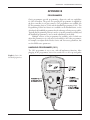
Curtis 1311 handheld programmer .......................................B-1
TABLES
TABLE
1:
High current connections ....................................................... 5
TABLE
2:
Connector J1: Inputs/Outputs ............................................... 7
TABLE
3:
Connector J2: CAN Bus ........................................................ 9
TABLE
4:
Connector J3: Serial Port ....................................................... 9
TABLE
5:
Connector J4: Specialty I/O ................................................ 10
TABLE
6:
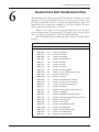
VCL Module IDs ................................................................. 45
TABLE
7:
Returned Errors .................................................................... 46
TABLE
iv
C-1: Specifications, 1310 controllers .......................................... C-1
Curtis 1310 Manual, Rev. B
1 — OVERVIEW
1
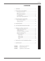
OVERVIEW
The Curtis 1310 vehicle system controller provides unprecedented flexibility
and ease-of-use. It contains a powerful microcontroller, FLASH memory, and a
wide range of inputs and outputs—which means it can be custom-programmed
to provide complex and unique functions for your specific application.
Custom software for the 1310 is written with VCL (Vehicle Control
Language), an innovative programming language developed by Curtis.
The 1310 controller integrates and expands systems through its industry
standard CAN bus communication port. The 1310 works seamlessly in
conjunction with the Curtis CAN-based SepEx and AC motor controllers,
such as the 1243, 1244, 1234/36/38, and 1298, as well as with the 1352 eXm
expansion module.
The 1310 controller can be applied to electric vehicles, non-electric
vehicles, and stationary control systems.
Fig. 1 Curtis 1310
Vehicle System Controller.
Features include:
✔ The powerful VCL programming language allows custom software
to be quickly and easily developed by OEMs for unique applications.
✔ CAN bus port allows customized vehicle systems and control.
✔ FLASH memory allows easy field upgrades and customization
on the assembly line.
✔ CANopen-compatible communication protocol provides control
and feedback to Curtis CAN-based motor controllers, as well as
many other CAN-based products.
More Features
Curtis 1310 Manual, Rev. B
☞
1
1 — OVERVIEW
✔ Extended software functions of VCL simplify the integration of OEM
requirements (BDI, hourmeters, PID, ramp, pot, CAN, etc.).
✔ Comprehensive Input and Output selection.
✔ Two analog outputs (0–10 V at up to 20 mA).
✔ Serial port for communication with the Curtis programmer
or Curtis Model 840 “Spyglass” display.
✔ Two quadrature encoder inputs.
✔ Up to 22 digital switch inputs and up to 16 output channels
(at up to 3 amps sink per channel) are available for a maximum
input/output combination of 22 channels.
✔ Two proportional valve control outputs are available (on 16-output
models only).
✔ Four software-configurable analog input channels available
for any combination of 2- and 3-wire pot inputs or 0–5V inputs.
✔ Real-Time Clock with battery back-up (optional).
✔ Built-in coil flyback diodes.
✔ Software and hardware watchdog circuits ensure proper software
operation.
✔ Rugged aluminum housing.
Familiarity with your Curtis controller will help you install and operate it properly. We encourage you to read this manual carefully. If you have questions,
please contact the Curtis office nearest you.
2
Curtis 1310 Manual, Rev. B
2 — INSTALLATION & WIRING
2
INSTALLATION AND WIRING
MOUNTING THE CONTROLLER
☞
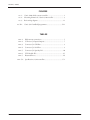
The outline and mounting hole dimensions for the 1310 controller are shown in
Figure 2. It is recommended that the controller be fastened securely to a clean,
flat metal surface with four #8 or M4 screws, using the holes provided. Care
should be taken to prevent water from splashing or resting on the connector
area. If possible, the controller should be mounted with the connector area facing downward and guarded from water and dust-born contaminants which
can degrade the electrical connections.
Fig. 2 Mounting
dimensions, Curtis 1310
vehicle system controller.
Dimensions in millimeters.
Curtis 1310 Manual, Rev. B
3
2 — INSTALLATION & WIRING
You will need to take steps during the design and development of your
end product to ensure that its EMC performance complies with applicable
regulations; see Appendix A for suggestions on managing EMC.
The Curtis 1310 controller contains ESD-sensitive components. Use
appropriate precautions in connecting, disconnecting, and handling the controller. See installation suggestions in Appendix A for protecting the controller
from ESD damage.
☞
C AU T I O N
Working on electrical systems is potentially dangerous. You should
protect yourself against uncontrolled operation, high current arcs, and
outgassing from lead acid batteries:
— Some conditions could cause the motor to
run out of control. Disconnect the motor or jack up the vehicle and get
the drive wheels off the ground before attempting any work on the motor
control circuitry.
UNCONTROLLED OPERATION
— Batteries can supply very high power, and arcing can
occur if they are short circuited. Always open the battery circuit before
working on the motor control circuit. Wear safety glasses, and use properly
insulated tools to prevent shorts.
HIGH CURRENT ARCS
— Charging or discharging generates hydrogen gas,
which can build up in and around the batteries. Follow the battery manufacturer’s safety recommendations. Wear safety glasses.
LEAD ACID BATTERIES
4
Curtis 1310 Manual, Rev. B
2 — INSTALLATION & WIRING: High Current Connections
HIGH CURRENT CONNECTIONS
There are two options for supplying power to the 1310 controller: using pins
23 and 24 on the J1 connector, or using the B- and B+ connection tabs.
Since the controller has many outputs, it is possible for it to draw a
considerable load from the battery. If more than 3 amps current is expected in
the total system, the B- connection tab must be used as the controller ground
reference. Likewise, if the system could draw more than 3 amps from B+, the
B+ connection tab must be used to power the controller.
If the driven loads are inductive, the load’s power must be connected to
the B+ connection tab, and the the B+ connection tab must be connected to
the battery; see wiring shown in Fig. 3, page 11.
When using the high current connection tabs, be careful not to bend or
break the tab while tightening the bolt. For best results, use a pressure washer
(convex side up) under the bolt head. This will help prevent the joint from
loosening over time.
To avoid overheating the joint, make sure the wire cable gage is sufficient to
carry the continuous and maximum loads that will be seen by the controller.
Table 1
NAME
Curtis 1310 Manual, Rev. B
High Current Connections
DESCRIPTION
B+
Battery Positive connection tab,
internally connected to J1-24; see Table 2.
B-
Battery Negative connection tab.
5
2 — INSTALLATION & WIRING: Low Current Connections
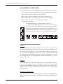
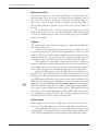
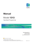
LOW CURRENT CONNECTIONS
Low current connections are made through four Molex Mini-Fit Jr. connectors.
J1
is a 24-pin connector containing most of the standard inputs/outputs.
J2
is a 6-pin connector dedicated to the CAN bus.
J3 is a 4-pin connector dedicated to the Curtis serial bus port,
used with the 1311 and 1314 programmers and the 840 Spyglass.
J4 is a 16-pin connector for the analog inputs/outputs
and encoder connections.
1
9
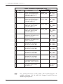
The 60 individual pins are characterized in Tables 2–5.
Often special VCL functions can be used to access or setup or
use of these signals. The VCL Functions column notes these when
appropriate. Each signal has a predetermined variable name or set
of variable names that allow the VCL access to the value or control
over the signal. These names are in the VCL References column.
1
2
1
3
1
12
3
4
4
6
13
24
8
16
J3
J2
J1
J4
Low current wiring recommendations
Encoders
All four encoder wires should be bundled together as they run between the
motor and controller logic connector. These can often be run with the rest of
the low current wiring harness. The encoder cables should not be run near
the motor cables. In applications where this is necessary, shielded cable should
be used with the ground shield connected to the I/O ground (pin 7) at only
the controller side. In extreme applications, common mode filters (e.g. ferrite
beads) could be used.
CAN bus
It is recommended that the CAN wires be run as a twisted pair. However,
many successful applications at 125 kBaud are run without twisting, simply
using two lines bundled in with the rest of the low current wiring. CAN wiring
should be kept away from the high current cables and cross it at right angles
when necessary.
All other low current wiring
The remaining low current wiring should be run according to standard practices.
Running low current wiring next to the high current wiring should always be
avoided.
6
Curtis 1310 Manual, Rev. B
2 — INSTALLATION & WIRING: Connector J1
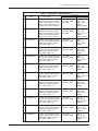
Table 2
Connector J1: Inputs/Outputs
RELATED VCL
PIN
NAME
DESCRIPTION
FUNCTIONS
REFERENCES
1
Input/Output 1
A digital input with an open
collector high-frequency PWM
output. This output also provides
output current feedback. Signal
is pulled to B- when output is on.
Put_PWM
Automate_PWM
Get_ADC
SW_1
SW_1_UP
SW_1_Down
PWM1
ADC15_Output
2
Input/Output 2
A digital input with an open
collector high-frequency PWM
output. This output also provides
output current feedback. Signal
is pulled to B- when output is on.
Put_PWM
Automate_PWM
Get_ADC
SW_2
SW_2_UP
SW_2_Down
PWM2
ADC16_Output
3
Input/Output 3
A switch to B+ digital input with
an open collector high-frequency
PWM output. Signal is pulled
to B- when output is on.
Put_PWM
Automate_PWM
SW_3
SW_3_UP
SW_3_Down
PWM3
4
Input/Output 4
A switch to B+ digital input with
an open collector high-frequency
PWM output. Signal is pulled
to B- when output is on.
Put_PWM
Automate_PWM
SW_4
SW_4_UP
SW_4_Down
PWM4
5
Input/Output 5
A switch to B+ digital input with
an open collector high-frequency
PWM output. Signal is pulled
to B- when output is on.
Put_PWM
Automate_PWM
SW_5
SW_5_UP
SW_5_Down
PWM5
6
Input/Output 6
A switch to B+ digital input with
an open collector high-frequency
PWM output. Signal is pulled
to B- when output is on.
Put_PWM
Automate_PWM
SW_6
SW_6_UP
SW_6_Down
PWM6
7
Input/Output 7
A switch to B+ digital input with
an open collector high-frequency
PWM output. Signal is pulled
to B- when output is on.
Put_PWM
Automate_PWM
SW_7
SW_7_UP
SW_7_Down
PWM7
8
Input/Output 8
A switch to B+ digital input with
an open collector high-frequency
PWM output. Signal is pulled
to B- when output is on.
Put_PWM
Automate_PWM
SW_8
SW_8_UP
SW_8_Down
PWM8
9
Input/Output 9
A switch to B+ digital input with
an open collector high-frequency
PWM output. Signal is pulled
to B- when output is on.
Put_PWM
Automate_PWM
SW_9
SW_9_UP
SW_9_Down
PWM9
10 Input/Output 10
A switch to B+ digital input with
an open collector high-frequency
PWM output. Signal is pulled
to B- when output is on.
Put_PWM
Automate_PWM
SW_10
SW_10_UP
SW_10_Down
PWM10
11 Input/Output 11
A switch to B+ digital input with
an open collector high-frequency
PWM output. Signal is pulled
to B- when output is on.
Put_PWM
Automate_PWM
SW_11
SW_11_UP
SW_11_Down
PWM11
12 Input/Output 12
A switch to B+ digital input with
an open collector high-frequency
PWM output. Signal is pulled
to B- when output is on.
Put_PWM
Automate_PWM
SW_12
SW_12_UP
SW_12_Down
PWM12
Curtis 1310 Manual, Rev. B
7
2 — INSTALLATION & WIRING: Connector J1
Table 2
Connector J1: Inputs/Outputs, cont’d
RELATED VCL
PIN
DESCRIPTION
FUNCTIONS
REFERENCES
13 Input/Output 13
A switch to B+ digital input with
an open collector high-frequency
PWM output. Signal is pulled
to B- when output is on.
Put_PWM
Automate_PWM
SW_13
SW_13_UP
SW_13_Down
PWM13
14 Input/Output 14
A switch to B+ digital input with
an open collector high-frequency
PWM output. Signal is pulled
to B- when output is on.
Put_PWM
Automate_PWM
SW_14
SW_14_UP
SW_14_Down
PWM14
15 Input/Output 15
A switch to B+ digital input with
an open collector high-frequency
PWM output. Signal is pulled
to B- when output is on.
Put_PWM
Automate_PWM
SW_15
SW_15_UP
SW_15_Down
PWM15
16 Input/Output 16
A switch to B+ digital input with
an open collector high-frequency
PWM output. Signal is pulled
to B- when output is on.
Put_PWM
Automate_PWM
SW_16
SW_16_UP
SW_16_Down
PWM16
17 Input 17
A switch to B+ digital input
(pulled low to B-). Switch this pin
to B+ to read as ON.
SW_17
SW_17_UP
SW_17_Down
18 Input 18
A switch to B+ digital input
(pulled low to B-). Switch this pin
to B+ to read as ON.
SW_18
SW_18_UP
SW_18_Down
19 Input 19
A switch to ground digital input
(pulled high to +15V). Switch
this pin to B- to read as OFF.
SW_19
SW_19_UP
SW_19_Down
20 Input 20
A switch to ground digital input
(pulled high to +15V). Switch
this pin to B- to read as OFF.
SW_20
SW_20_UP
SW_20_Down
21 Input 21
A switch to ground digital input
(pulled high to +15V). Switch
this pin to B- to read as OFF.
SW_21
SW_21_UP
SW_21_Down
22 Input 22
A switch to ground digital input
(pulled high to +15V). Switch
this pin to B- to read as OFF.
SW_22
SW_22_UP
SW_22_Down
23 B-
CAN be used as a low power
(<2 amp) ground reference or for
switch inputs 12–22 B- reference.
24 B+
Can be used to power the system
(<2 amps) or for B+ reference
for switches, etc.
☞
8
NAME
Setup_BDI
ADC13_Output
KSI_Filtered
KSI_Raw
Note: Model 1310-5210 is not fully “stuffed.” This model has Outputs 9–16
available, and Inputs 1–13, 16, and 19–22. Outputs 14 and 15 have over
200kΩ output impedance.
Curtis 1310 Manual, Rev. B
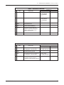
2 — INSTALLATION & WIRING: Connectors J2 & J3
Table 3
Connector J2: CAN Bus
RELATED VCL
PIN
NAME
DESCRIPTION
FUNCTIONS
1
CAN Hi
Positive CAN Bus rail.
Setup_CAN
Setup_Mailbox
Send_Mailbox
etc...
2
CAN Lo
Negative CAN Bus rail.
Setup_CAN
Setup_Mailbox
Send_Mailbox
etc...
3
GND
Ground reference.
4
+5V
+5V for remote module(s).
5
Term H
Connect Term H to Term L to
create an end-of-bus termination
(adds a 120Ω resistor across
CAN Hi and CAN Lo).
6
Term L
See Term H description above.
Table 4
REFERENCES
Connector J3: Serial Port
RELATED VCL
PIN
NAME
DESCRIPTION
1
RxD
Serial Receive line for programmer
and Spyglass communications.
2
GND
Communications ground.
3
TxD
Serial Transmit line for programmer
and Spyglass communications.
4
PWR
+12V power; the output current
of this pin and +5V (J4-15) is
combined and monitored at ADC12.
Curtis 1310 Manual, Rev. B
FUNCTIONS
REFERENCES
Setup_Serial
Put_Spy_Message
Setup_Serial
Put_Spy_Message
ADC12_Output
9
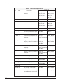
2 — INSTALLATION & WIRING: Connector J4
Table 5
Connector J4: Specialty I/O
RELATED VCL
PIN
NAME
DESCRIPTION
FUNCTIONS
REFERENCES
1
Encoder 1A
Pulse count input, or encoder
channel A.
2
Encoder 1B
Encoder channel B.
3
Encoder 2A
Pulse count input or encoder
channel B.
4
Encoder 2B
Encoder channel B.
5
Pot High
The high voltage reference
for the four potentiometer inputs.
Get_Pot
Get_ADC
POT_High
ADC1
ADC_Output
6
Wiper 1
A generic 0–5V input which can
also be set up as a potentiometer
wiper input.
Get_Pot
Setup_Pot
Setup_Pot_Filtered
Get_ADC
POT1_Output
ADC2_Output
7
Wiper 2
A generic 0–5V input which can
also be set up as a potentiometer
wiper input.
Get_Pot
Setup_Pot
Setup_Pot_Filtered
Get_ADC
POT2_Output
ADC3_Output
8
Wiper 3
A generic 0–5V input which can
also be set up as a potentiometer
wiper input.
Get_Pot
Setup_Pot
Setup_Pot_Filtered
Get_ADC
POT3_Output
ADC4_Output
9
Wiper 4
A generic 0–5V input which can
also be set up as a potentiometer
wiper input.
Get_Pot
Setup_Pot
Setup_Pot_Filtered
Get_ADC
POT4_Output
ADC5_Output
10 Pot Low
The low voltage reference
for the four potentiometer inputs.
Get_Pot
Get_ADC
POT_Low
ADC6_Output
11 Analog Output 1
0–10V analog output.
Put_DAC
Automate_DAC
DAC1
12 Analog Output 2
0–10V analog output.
Put_DAC
Automate_DAC
DAC2
14 PWR_UP
B+ input that can be used to
to power up the 1310 controller.
Get_ADC
ADC7_Output
15 +5V
+5V to power sensors. Can supply
up to 200 mA. The output current
is monitored at ADC11.
Get_ADC
ADC11_Output
16 GND
Ground reference.
Setup_Encoder
Get_Enc_Count
Get_Enc_Dir
Get_Enc_Vel
Get_Enc_Error
ENC1
ENC1_Count
ENC1_Dir
ENC1_Vel
ENC_Error
SW_23
SW_24
Setup_Encoder
Get_Enc_Count
Get_Enc_Dir
Get_Enc_Vel
Get_Enc_Error
ENC2
ENC2_Count
ENC2_Dir
ENC2_Vel
ENC_Error
SW_25
SW_26
13 Not used
10
Curtis 1310 Manual, Rev. B
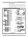
2 — INSTALLATION & WIRING: Wiring Diagram
CONTROLLER WIRING
Because the 1310 controller is so versatile, there is no “standard” wiring configuration. The diagram shown as Figure 3 illustrates some of the possibilities
for the various inputs and outputs. The power and battery connections shown
are fairly standard, although other configurations are possible. The following
paragraphs walk through the diagram.
Fig. 3 Wiring diagram, Curtis 1310 vehicle system controller.
Curtis 1310 Manual, Rev. B
11
2 — INSTALLATION & WIRING: Wiring
Power connection
The battery is connected to the 1310 controller’s power tabs through a fuse
and a keyswitch. The power tabs are used because there are inductive loads on
the system (Aux Contactor and Proportional Valve coils) which could cause
the current to exceed 3 amps. The fuse is required to protect the wiring, as
the controller could draw significant power if there were a short or failure in
the unit.
The keyswitch is used to “start” the system. Both the B+ power tab and
the B+ signal at J1-24 are used as the Keyswitch Input. When the keyswitch
is closed, the B+/KSI input goes high, the controller powers up, and the BDI
functions are enabled.
Outputs
☞
The system shown in Figure 3 has two high-power outputs and two LEDs that
run off keyswitch power.
The first power output drives a proportional valve coil. Outputs 1 and 2
are special in that they have internal current feedback lines. VCL can use this
signal in a PID loop to regulate current, which is necessary to properly control
the position (and flow) in a proportional valve. Outputs 1 through 4 also run
at a higher frequency and thus can provide a smoother current (less ripple).
The second power output drives a basic contactor coil. It is connected to
Output 2, which has a current feedback signal. In this case, VCL can use the current feedback signal to ensure that the coil is connected and drawing the proper
current when on. In this way, enhanced fault diagnostics can be performed.
Using the PWM outputs to drive the LEDs allows the the brightness of
the LEDs to be varied. The frequency is too high for the human eye to see any
flickering. Note that a dropping resistor must be used because even low duty
cycle PWM applies full battery voltage is short bursts, and this will destroy the
LED without a dropping resistor limiting the current. Note that the internal
impedance to ground of the driver will cause leakage current to flow through the
LEDs even when the output driver is off. Refer to the Digital Output Specifications (page 15) when calculating the leakage current. This leakage current can
be enough (> 2 mA) to light high efficiency LEDs. Model 1310-5210 provides
two output drivers (Outputs 14 and 15) that do not have leakage current issues
and may therefore be the best suited for driving LEDs.
Switch inputs
All the outputs can be used as active high inputs (On when connected to B+).
There are four special inputs that are active low (On when connected to B-).
If an output is used as an input (see, for example, Input/Output 15 in the
wiring diagram), VCL must take care not to turn on that output or a direct short
to B+ could be established through the switch and the internal FET driver.
12
Curtis 1310 Manual, Rev. B
2 — INSTALLATION & WIRING: Wiring
Analog inputs
Three types of analog inputs are used. The first two inputs use a 0–5V input.
The next is a 3-wire connection for a potentiometer using both Pot High and
Pot Low and the third is a 2-wire potentiometer or rheostat.
Note that in all cases, the VCL code must be written to provide the necessary wiring and potentiometer fault checking. To accomplish this, the 1310
provides the measured voltage readings of Pot High and Pot Low connections.
Monitoring these values can indicate if there is a short to B+ or B-. Using the
Pot High and Pot Low connections for the potentiometer or rheostat will also
provide a small lower and (when using Pot High) upper bound to the analog
input. Knowing this, proper range checking in VCL can be performed for additional fault diagnostics.
Encoder and pulse inputs
☞
The 1310 has two quadrature encoder inputs. Using A and B channels with a
quadrature encoder allows velocity, position (count), and direction detection.
Tying the A and B channels together, as shown on Encoder 2, allows the input
to measure a single pulse train. In this configuration, the 1310 will either count
(ENC_Count mode) or measure speed magnitude (Enc_Velocity mode); the
ENC2_DIR variable is not valid in this configuration.
Power for the encoder can be derived from the +5V output and Ground
pins found on J4. The +5V output has an output current measurement. VCL
can use this value to determine if the encoder and/or any other sensors are connected and drawing the proper current. This can be used to provide additional
fault diagnostics.
Note: If the encoder inputs are set up in velocity mode, the direction
flag will not be accurate below a low speed threshold. The direction bit may
stay in the last direction and may not return to 0 when the speed is at zero.
The VCL code must be written to read the velocity variable and doublecheck
the direction bit in this case; see page 36.
Analog outputs
The two analog outputs can be used to interface to various analog devices.
Here, Analog Output 1 is used to control the throttle input of a Curtis 1204
motor controller. Note that most throttle inputs are 0–5 V while the 1310 can
provide up to 10 volts.
Analog Output 2 is being used to drive a gage, such as a Curtis enGage 2
or simple voltmeter. VCL code can use this output to display a wide range of
data—for example, the state of the battery charge, position of the potentiometer
wipers, or speed of the encoder.
Curtis 1310 Manual, Rev. B
13
2 — INSTALLATION & WIRING: I/O Signal Specifications
INPUT/OUTPUT SIGNAL SPECIFICATIONS
The input/output signals wired to the J1, J2, J3, and J4 connectors can be
grouped by type as follows; their electrical characteristics are discussed below.
—
—
—
—
—
—
digital inputs
digital outputs
analog inputs
analog output
power
communications.
Digital inputs
These signal lines can be used as digital (on/off ) inputs. Normally, the On signal
is made by a connection direct to B+ and Off is direct to B-. Inputs 1 through
18 will pull low (Off ) if no connection is made. Inputs 19 through 22 and the
encoder inputs will pull high (On) if no connection is made.
Inputs 1 through 18 are associated with driver outputs. Inputs 19 through
22 and the encoder inputs are low voltage “TTL” level inputs and can be used
when connecting to other low voltage (5V) logic circuits or sensors. The encoder
channels are normally used for pulse count inputs from quadrature (2-channel) encoders, but they may also be used as 5V logic-level digital inputs. Take
careful note of their much lower voltage range.
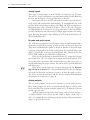
DIGITAL INPUT SPECIFICATIONS
LOGIC
THRESHOLDS
VOLTAGE
RANGE
ESD
TOLERANCE
24–48V models:
about 5.4 kΩ
48–96V models:
about 22 kΩ
* see note below
24–48V models:
-0.5 to 64 V
48–96V models:
-0.5 to 124 V
± 8 kV
(air discharge)
24–48V models:
Low = 7.5 V
High = 15.8 V
48–96V models:
Low = 14.1 V
High = 29.7 V
24–48V models:
about 5.4 kΩ
48–96V models:
about 22 kΩ
24–48V models:
-0.5 to 64 V
48–96V models:
-0.5 to 124 V
± 8 kV
(air discharge)
All models:
High = 3.8 V
Low = 1.8 V
All models:
about 4.5 kΩ
24–48V models:
-0.5 to 64 V
48–96V models:
-0.5 to 124 V
± 8 kV
(air discharge)
Rising edge=
3.0 V
Falling edge=
2.0 V
All models:
about 4.7 kΩ
All models:
-0.5 to 5.5 V
± 8 kV
(air discharge)
SIGNAL NAME
PIN
Input/Output 1–16
J1-1
thru
J1-16
24–48V models:
Low = 7.5 V
High = 15.8 V
48–96V models:
Low = 14.1 V
High = 29.7 V
Input 17–18
J1-17
thru
J1-18
Input 19–22
J1-19
thru
J1-22
Encoder 1A,1B,2A,2B J4-1
thru
J4-4
INPUT
IMPEDANCE
Tolerance of above values ±5%.
* Outputs 14 and 15 on Model 1310-5210 have over 200 kΩ output impedance.
14
Curtis 1310 Manual, Rev. B
2 — INSTALLATION & WIRING: I/O Signal Specifications
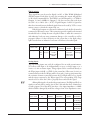
Digital outputs
These signal lines can be used as digital (on/off ) or Pulse Width Modulated
(PWM) outputs. Each driver is active low, meaning the output will pull low
(to B-) when commanded On. The PWM is at a fixed frequency (∼ 9.7kHz for
Outputs 1–4 and ∼ 400Hz for Outputs 5–16), but can vary duty cycle from
0% (Off = 0) to 100% (On = 32767). Digital Outputs 1 and 2 are special as
these have internal current feedback signals that can be used by VCL to create
current sources or check the output load, etc.
If the digital outputs are connected to inductive loads, the B+ tab must be
connected to the battery source. This connection provides a path for the internal
freewheel diodes to clamp the turn-off spike. Failure to make this connection
with inductive loads can cause permanent damage to the controller as well as
propagate failures of other electronics in the system due to the high voltage
spike caused when an inductive load turns off without a freewheel path.
DIGITAL OUTPUT SPECIFICATIONS
SIGNAL NAME
Input/Output 1–16
PIN
PWM
OUTPUT
CURRENT
FREQUENCY
J1-1 0 to 100%
thru duty cycle
J1-16
Outputs 1–4:
∼ 9.7 kHz
Outputs 5–16:
∼ 400 Hz
PROTECTED
VOLTAGE
ESD
TOLERANCE
Sink 3 amps 24–48V models:
± 8 kV
-0.5 to 64 V (air discharge)
48–96V models:
-0.5 to 124 V
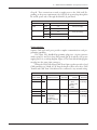
Analog inputs
☞
The four analog inputs can easily be configured for use with potentiometers.
VCL allows each input to be independently set up as a voltage input or as a
2-wire or 3-wire resistance input. Voltage inputs can be connected directly to
the Wiper input (with B- or GND for the return line). Rheostats (2-wire) are
connected between the Pot Wiper and Pot Low, and a 3-wire potentiometer has
the resistance element connected between the Pot High and Pot Low signals
and the wiper connected to the Wiper signal. The corresponding VCL setup
must be used to allow the 1310 to properly detect and scale the signal.
Although designed to be used with potentiometers, Pot High and Pot Low
signals are monitored by analog pins in the 1310 and thus have a limited use
as analog inputs. Note that these pins have a low input impedance (~ 680Ω)
which could be damaged by moderate voltages from a low impedance source.
ANALOG INPUT SPECIFICATIONS
PIN
OPERATING
VOLTAGE
INPUT
IMPEDANCE
PROTECTED
VOLTAGE
ESD
TOLERANCE
J4–6 thru J4-9
0 to 5 V
5 kΩ
- 1 V to 30 V
± 8 kV
(air discharge)
Pot High
J4-5
0 to 5 V
680 Ω to +5 V
- 1 V to 30 V
± 8 kV
(air discharge)
Pot Low
J4-10
0 to 5 V
680 Ω to ground
- 1 V to 8 V
± 8 kV
(air discharge)
SIGNAL NAME
Wiper 1–4
Curtis 1310 Manual, Rev. B
15
2 — INSTALLATION & WIRING: I/O Signal Specifications
Analog outputs
☞
C AU T I O N
☞
Two signals provide low power analog outputs. These outputs are generated
from filtered PWM signals and have about 1% ripple. The settling time (within
2% of final output) is about 30 ms for a 0–10V step. The Analog Outputs are
protected against shorts to B+ or B-.
During a FLASH software download, the DAC output voltages will float
up and can reach as high as 10 volts. Make sure that your vehicle system is safe
and can tolerate this event.
If the battery system droops below 20 volts, the DAC outputs will not
reach the 10V output specification and will start dropping as the battery voltage drops below 20 volts.
ANALOG OUTPUT SPECIFICATIONS
SIGNAL NAME
Analog Output 1–2
PIN
J4-11
& J4-12
OUTPUT
VOLTAGE
OUTPUT
IMPEDANCE
PROTECTED
VOLTAGE
ESD
TOLERANCE
0 to 10 V
about 33 kΩ
- 1 V to 124 V
± 8 kV
(air discharge)
Power
Group A: These signals provide power for the various sensors and communication
systems that might be connected to the 1310. The PWR signal is normally only
used for powering the 1311 handheld programmer or the Curtis 840 Spyglass,
but can be used to power other small sensors or electronics. These three power
supply signals are current limited. The limited supply current can be split between
these power pins as long as the combined total does not exceed 200 mA.
POWER SPECIFICATIONS: Group A
PIN
OUTPUT
VOLTAGE
OUTPUT
CURRENT
ESD
TOLERANCE
+5 Volts
J4-15
5 V ±5%
200 mA max *
± 8 kV (air discharge)
CAN +5V
J2-4
5 V ±5%
200 mA max *
± 8 kV (air discharge)
PWR (Serial Port)
J3-4
13.75 V ±5%
200 mA max *
± 8 kV (air discharge)
SIGNAL NAME
* The combined current of +5 Volts, CAN +5V, and PWR cannot exceed 200 mA.
16
Curtis 1310 Manual, Rev. B
2 — INSTALLATION & WIRING: I/O Signal Specifications
Group B: These connections are used to supply power to the 1310 itself. Depending on the power requirements, the 1310 can be powered up through the
B+ and B- power tabs or through the Mini-Fit Jr. pins listed.
POWER SPECIFICATIONS: Group B
SIGNAL NAME
B+/KSI
BPWR_UP
PIN
MAX CURRENT
ESD TOLERANCE
J1-24
3 A*
± 8 kV (air discharge)
B+ TAB
40 A
J1-23
3 A*
B- TAB
40 A
J4-14
3A
± 8 kV (air discharge
± 8 kV (air discharge)
* The B+ and B- power tabs must be used if more than 3A is expected in the system, or if the driven loads are inductive.
Communications
Separate CAN and serial ports provide complete communications and programming capability.
The Curtis 1311 handheld programmer plugs into a 4-pin connector
wired to pins J3-1 and J3-3, along with ground (pin J3-2) and the +12V power
supply (pin J3-4); see wiring diagram, Figure 3. The Curtis Model 840 Spyglass
can plug into the same 4-pin connector.
Wiring the CAN Term H and CAN Term L pins together provides a local
CAN termination of 120 Ω, 0.5 W; keep the length of these wires short. CAN
Term H and CAN Term L should never be connected to any external wiring.
COMMUNICATIONS PORT SPECIFICATIONS
SIGNAL NAME
Curtis 1310 Manual, Rev. B
PIN
CAN Hi
CAN Lo
J2-1
J2-2
CAN Term H
CAN Term L
J2-5
J2-6
TxD
RxD
J3-3
J3-1
SUPPORTED
PROTOCOL/DEVICES
CANopen
DATA RATE
up to 1 Mbps
PROTECTED
VOLTAGE
Continuous=
- 36 V to
(MaxV + 10 V)
Transient=
± 200 V
ESD
TOLERANCE
± 8 kV
(air discharge)
(no connection
± 8 kV
to external wiring) (air discharge)
Curtis 840 Display,
1311 Handheld
Programmer,
1314 PC Programming
Station
as required,
9.6 to 56 kbps
-0.3 to 12 V
± 8 kV
(air discharge)
17
3 — PROGRAMMABLE PARAMETERS
3
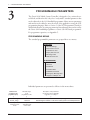
PROGRAMMABLE PARAMETERS
The Curtis 1310 Vehicle System Controller is designed to be a universal control block, and therefore has only a few “ready-made” standard parameters that
can be adjusted via the 1311 handheld programmer. Many custom parameters
and menus can be added to meet the needs of the application, using the VCL
programming language. Refer to Section 5 of the VCL Programmer’s Guide for
detailed information on setting up parameter lists and menus that can be read by
the Curtis 1311 handheld programmer or Curtis 1314 PC-based programmer.
For programmer operation, see Appendix C.
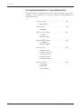
PROGRAMMING MENUS
The standard programmable parameters are grouped these two menus:
BATTERY MENU
—Nominal Voltage
—Reset Volts Per Cell
—Full Volts Per Cell
—Empty Volts Per Cell
—Discharge Time
—BDI Reset Percent
CAN INTERFACE MENU
—Master ID
—Slave ID
—Baud Rate
—Heartbeat Rate
—PDO Timeout Period
—Emergency Message Rate
—Suppress CANopen Init
Individual parameters are presented as follows in the menu charts:
Parameter name
as it appears in the
programmer display
Allowable range
in the
programmer’s units
Description of the parameter’s
function and, where applicable,
suggestions for setting it
⇓
⇓
⇓
Nominal Voltage
Nominal_Voltage
⇑
Parameter name
in VCL
18
24–48 V
1536–3072
Must be set to the system’s nominal battery voltage. This value is used in
determining the number of cells in the battery pack for the BDI parameters.
⇑
Allowable range
in VCL units
Curtis 1310 Manual, Rev. B
3 — PROGRAMMABLE PARAMETERS: Battery Parameters
Battery Discharge Indicator algorithm
The 1310 controller contains a sophisticated battery state-of-charge algorithm.
Set up properly, this algorithm can track the remaining battery charge (in percent) using only a voltage reading from the B+ power tab or J1-24. To achieve
any accuracy, it is critical to set the BDI parameters correctly for the vehicle,
battery, and normal duty cycle of the application. Note that many of the parameters are in volts per cell. A normal 24V battery has 12 cells.
The remaining battery capacity is automatically updated into the variable
BDI_Percentage.
BATTERY MENU
PARAMETER
ALLOWABLE
RANGE
Nominal Voltage
Nominal_Voltage
24–48 V
1536–3072
Must be set to the vehicle’s nominal battery pack voltage. This value is
used in determining the number of cells in the battery pack for the BDI
How so?
parameters.
Reset Volts Per Cell
BDI_Reset_Volts_Per_Cell
0.00–3.00 V
000–3000
At power up, the BDI is reset to 100% if the battery is measured above
this setting. Typical value is 2.09 V.
Reset Volts Per Cell must be set higher than Full Volts Per Cell.
Full Volts Per Cell
BDI_Full_Volts_Per_Cell
0.00–3.00 V
000–3000
The BDI will output 100% (full) while the average voltage per cell resding
is above this setting.
Empty Volts Per Cell
BDI_Empty_Volts_Per_Cell
0.00–3.00 V
000–3000
The BDI will output 0% (empty) when the average voltage per cell reading
is below this setting.
Discharge Time
BDI_Discharge_Time
0–600 min.
0–600
The time it will take the BDI to go from 100% to 0% at maximum current
drawl.
BDI Reset Percent
BDI_Reset_Percent
0–100 %
0–100
Curtis 1310 Manual, Rev. B
DESCRIPTION
If the previous BDI % value was above this point at power up, the BDI
will not reset, even if the battery is measured above the Reset Volts Per
Cell level. This will prevent a slightly discharged battery from “floating” and
resetting the BDI at every power up.
19
3 — PROGRAMMABLE PARAMETERS: CAN Interface Parameters
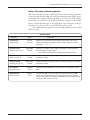
CANopen interface
The 1310 controller can be easily interfaced to other CANopen modules. The
parameters in the CAN Interface menu work with VCL to set up the basic
CANopen IDs and rates. Refer to the Section G of the VCL Common Functions Manual for information on setting up CANopen PDO, SDO, and other
CAN-related functions.
CAN INTERFACE MENU
PARAMETER
ALLOWABLE
RANGE
Master ID
CAN_Master_ID
0–3
0–3
CAN ID for incoming messages to a CANopen Slave system.
CAN Slave ID
CAN_Slave_ID
0 – 31
0 – 31
CAN ID for outgoing messages from a CANopen Slave system.
first 7 bits of the 11-bit identifier (the COB ID).
Baud Rate
CAN_BAUD_Rate
0–2
0–2
Sets the CAN baud rate for the CANopen Slave system:
0=125 kbps, 1=250 kbps, 2=500 kbps.
DESCRIPTION
Heartbeat Rate
Heartbeat_Rate
16 – 200 ms
4 – 50
Sets the rate at which the CAN heartbeat messages are sent by the
CANopen Slave system.
PDO Timeout Period
CAN_PDO_Timeout_Period
0 – 200 ms
0 – 50
Sets the PDO timeout period for the CANopen Slave system. After the
slave controller has sent a PDO MISO, it will declare a PDO Timeout Fault
if the master controller has not sent a reply PDO MOSI message within the
set time. Either PDO1 MOSI or PDO2 MOSI will reset the timer. Setting the
PDO Timeout Period = 0 will disable this fault check.
Emergency Message Rate
CANopen_Emergency_
Message_Rate
16 – 200 ms
4 – 50
Sets the minimum rate between CAN emergency messages from the
CANopen Slave system. This prevents quickly changing fault states from
generating so many emergency messages that they flood the CAN bus.
Suppress CANopen Init
Suppress_CANopen_Init
20
0–1
0–1
When Suppress CANopen Init is set = 1, at power up the initialization
of the CANopen system is suppressed. Typically this is done so that the
VCL program can make changes to the CANopen system before enabling
it (by setting the variable Suppress_CANopen_Init = 0 and running the
Setup_CAN() function).
Curtis 1310 Manual, Rev. B
4a — MONITOR MENU
4a
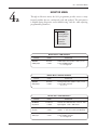
MONITOR MENU
Through its Monitor menu, the 1311 programmer provides access to many
internal variables that are continuously read and updated. This information
is helpful during diagnostics and troubleshooting, and also while adjusting
programmable parameters.
MONITOR MENU
—PWM Outputs
—Analog Outputs
—Analog Inputs
—Pot Inputs
—Switches
—CAN Status
Monitor Menu: PWM OUTPUTS
VARIABLE
Channel #
PWM#_Output
DISPLAY
RANGE
0–32767
0–32767
DESCRIPTION
PWM output value (32767 = 100%) of one
of the 16 PWM signals.
# = 1 through 16.
Monitor Menu: ANALOG OUTPUTS
VARIABLE
Channel #
DAC#_Output
DISPLAY
RANGE
0–32767
0–32767
DESCRIPTION
Analog output value (32767 = 10 V) of one
of the 2 DAC channels.
# = 1 or 2.
Monitor Menu: ANALOG INPUTS
VARIABLE
KSI Filtered
KSI_Filtered
Curtis 1310 Manual, Rev. B
DISPLAY
RANGE
DESCRIPTION
0–100.0 V
0–10000
Filtered and calibrated value of the B+ / KSI
input signals. 1 volt = 100 counts.
KSI Raw
KSI_Raw
0–1023
0–1023
Unfiltered (raw) value of the B+ / KSI input
signals. ~1 volt = 9.5 counts (uncalibrated).
Channel #
ADC#_Input
0–1023
0–1023
Analog input value (~1023 = 5 volts) of one
of the 16 ADC channels.
# = 1 through 16.
21
4a — MONITOR MENU
Monitor Menu: POT INPUTS
VARIABLE
DISPLAY
RANGE
Pot #
Pot#_Input
0–32767
0–32767
Analog value of the Pot Wiper input signal.
# = 1 through 4.
Pot High
Pot_High
0–32767
0–32767
Analog reading of the Pot High signal
Pot Low
Pot_Low
0–32767
0–32767
Analog reading of the Pot Low signal.
DESCRIPTION
Monitor Menu: SWITCHES
VARIABLE
Switch #
SW_#
DISPLAY
RANGE
On / Off
0–255
DESCRIPTION
Switch state.
# = 1 through 26.
#1 – #22 = the 22 inputs (J1-1 – J1-22);
#23 – #26 = the 4 encoder channels (J4-1 – J4-4).
22
Curtis 1310 Manual, Rev. B
4a — MONITOR MENU
Monitor Menu: CAN STATUS
DISPLAY
RANGE
VARIABLE
CAN NMT State
CAN_NMT_State
0–127
0–127
PDO1 MOS1 COB ID
PDO1 MOSI Byte Map*
PDO1 MISO COB ID
PDO1 MISO Byte Map*
PDO2 MOS1 COB ID
PDO2 MOSI Byte Map*
PDO2 MISO COB ID
PDO2 MISO Byte Map*
DESCRIPTION
CAN network state:
0=initialization, 4=stopped, 5=operational,
127=pre-operational.
0–65355
Communication object ID for the PDO1
Master Out Slave In message.
0 – 232
Mapping objects for PDO1 MOSI’s eight
bytes.
0–65355
Communication object ID for the PDO1
Master In Slave Out message.
0 – 232
Mapping objects for PDO1 MISO’s eight
bytes.
0–65355
Communication object ID for the PDO2
Master Out Slave In message.
0 – 232
Mapping objects for PDO2 MOSI’s eight
bytes.
0–65355
Communication object ID for the PDO2
Master In Slave Out message.
0 – 232
Mapping objects for PDO2 MISO’s eight
bytes.
* Each of these byte maps is a submenu containing 8 variables,
one for each byte. Each variable is 32 bits. For example, the
PDO1 MOSI Byte Map menu looks like this:
PDO1 MOSI Byte Map
Curtis 1310 Manual, Rev. B
1
0 – 232
Mapping object for byte 1 of PDO1 MOSI.
2
0–2
Mapping object for byte 2 of PDO1 MOSI.
3
0–2
Mapping object for byte 3 of PDO1 MOSI.
4
32
0–2
Mapping object for byte 4 of PDO1 MOSI.
5
0 – 232
Mapping object for byte 5 of PDO1 MOSI.
6
0–2
Mapping object for byte 6 of PDO1 MOSI.
7
32
0–2
Mapping object for byte 7 of PDO1 MOSI.
8
0 – 232
Mapping object for byte 8 of PDO1 MOSI.
32
32
32
23
4b — CONTROLLER INFO MENU
4b
24
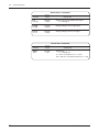
CONTROLLER INFORMATION MENU
This menu provides ID and version numbers for your controller hardware and
software.
CONTROLLER INFORMATION MENU
VARIABLE
DISPLAY
RANGE
Model Number
Model_Number
0–4294967295
0–4294967295
Model number. For example, if you have a
controller with the model number 1310-4501,
the Model Number variable will have a value
of 13104501.
Serial Number
Serial Number
0–4294967295
0–4294967295
Serial number. For example, if the serial
number printed on your controller is
08045L.11493, the Serial Number variable
will have the value of 11493.
Mfg Date Code
Manuf_Date
0–32767
0–32767
Controller date of manufacture, with the first
two digits indicating the year and the last
three indicating the day. For example, if the
serial number printed on your controller is
08045L.11493, the Mfg Date Code variable
will have the value of 08045 (45th day of
2008).
Hardware Version
Hardware_Ver
0–32.767
0–32767
The hardware version number uniquely
describes the combination of electronic
assemblies used in the controller.
OS Version
OS_Ver
0–32767
0–32767
Version number of the operating system
software that is loaded into the controller.
This variable specifies the major version
number of the controller’s operating system.
Build Number
Build_Number
0–32767
0–32767
Build number of the operating system
software that is loaded into the controller.
This variable specifies the minor version
number of the controller’s operating system.
SM Version
SM_Ver
0–327.67
0–32767
Version number of the Start Manager
software that is loaded into the controller.
Param Blk Version
Param_Blk_Ver
0–327.67
0–32767
Version number of the parameter block that
is loaded into the controller.
VCL App Version
VCL_App_Ver
0–327.67
0–32767
Version number of the VCL application
software that is loaded into the controller.
This value is set in the VCL program by
assigning a value to the VCL_App_Ver
variable.
DESCRIPTION
Curtis 1310 Manual, Rev. B
5 — VCL
5
VEHICLE CONTROL LANGUAGE (VCL)
The Curtis 1310 Vehicle System Controller is similar to other programmable
logic controllers with application-specific functions generally found in the
vehicle control industry. Key to the flexibility and application of the 1310 is a
proprietary software language, VCL (Vehicle Control Language). VCL software
provides a fast and easy way to implement unique and complex vehicle control
functions.
The VCL programming language will feel very familiar to anyone who
has worked with BASIC, Pascal, or C. VCL code can be written using either a
code-writing program (such as Code Warrior or UltraEdit) or a non-formatting
text program (such as Windows Notepad).
VCL is compiled, managed, and downloaded into the 1310 using the
Curtis WinVCL PC program. The install process for WinVCL will also install
two manuals on your PC—the VCL Programmer’s Guide and the VCL Common Functions Manual. These manuals describe the common portions of the
VCL programming language, and include more detailed information about
VCL than is included here. They should be your starting point if you are not
yet familiar with WCL. A third manual, the WinVCL User’s Guide, should
also be reviewed prior to starting your VCL programming.
This section of the manual describes additional aspects and functions of
VCL that are unique to the 1310, and also provides a basic summary overview
of VCL.
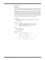
Summary of VCL Basics
• VCL is not case-sensitive:
put_pwm(), Put_PWM(), and PUT_PWM() are identical.
• Spaces in variable and constant names are not allowed in VCL;
use underscores in place of spaces.
Example: SW_1 is the VCL name for switch input #1.
• Functions are followed by parentheses; for example:
GET_ADC() is a function
ADC7_Output is a variable.
• Logical statements must be inside parentheses; examples:
IF (setpoint >50)
ELSE IF ((setpoint <20) & (temperature >100)).
• Comments are preceded by semicolons; for example:
; This is a comment.
Curtis 1310 Manual, Rev. B
25
5 — VCL
VARIABLE TYPES & QUANTITIES
VCL provides dedicated space in which to store custom variables. There are
four types of variables, based on their type of storage:
• volatile memory (RAM)
• automatic non-volatile memory (EEPROM)
• non-volatile block memory (EEPROM)
• parameter non-volatile memory (EEPROM).
☞
Volatile memory variables (RAM) are stored only while power is on; they
are lost at power-down. This is the memory used to hold temporary calculations,
counters, and other variables that are needed only while running. The generic
VCL names for these variables are User1–User120. They must be initialized
on power-up by explicit VCL assignments (e.g., User1 = 12); otherwise they
will be reset to a value of 0.
Automatic non-volatile memory variables (EEPROM) are labeled NVUser1–NVUser15 in VCL. These 15 variables are stored cyclically while running
and at power-down. They can be recalled by using the NVM_NVUser_Restore
function is used. Thus, they are automatically saved and can then be recalled at
the next power-on cycle, which restores their previous values. See the section
on non-volatile memory access in the VCL Common Functions manual for
more information.
Non-volatile block memory (EEPROM) is 38 blocks of 15 variables (total
of 570 variables), which are stored and recalled using the functions NVM_Block_
Read and NVM_Block_Write. The 38 blocks are called NVM3–NVM40. The
read and write functions will retrieve and store RAM variables (such as User20)
from and into the EEPROM blocks. See the section on non-volatile memory
access in the VCL Common Functions manual for more information.
Parameter non-volatile variables (EEPROM) are a special type of EEPROM variable that is intended to be used to create OEM-defined 1311/1314
parameters. These parameters can be defined as 16-bit words by using the
P_User variables or they can be defined as single bits (On/Off ) by using the
P_UserBit variables. Parameter variable values are modified and stored through
the programmer interface (i.e., when a 1311 user changes a parameter setting
using the 1311). They can be read or written to in the VCL code. However, it
is important to note that writing to parameters in VCL will not be stored
in EEPROM nor read by the 1311 or 1314 programmer. At the next power
down, the data changes made by VCL will be lost. These variables are intended
to be used only for creating and defining 1311/1314 parameters.
TYPE
RAM
120 16-bit variables
160 single-bit variables
RANGE
User1 – User120
UserBit1 – UserBit10
NVUser EEPROM
15 variables
NVUser1 – NVUser15
Block EEPROM
38 blocks
NVM3 – NVM40
(15 variables each)
Parameters EEPROM
26
QUANTITY
100 16-bit variables
160 single-bit variables
P_User1 – P_User100
P_UserBit1 – P_UserBit10
Curtis 1310 Manual, Rev. B
5 — VCL
VCL RUNTIME RATES
VCL is an interpreted language. Each line of VCL code is converted by the
WinVCL compiler into an array of pseudo-code which can then be flash loaded
into the controller. The controller interprets these pseudo-codes one line at a
time while the system is running (powered). The table below lists the service
rate at which the VCL interpreter runs each of the various functions, and also
lists how many instances of each function are available to the VCL software.
FUNCTION
Curtis 1310 Manual, Rev. B
FUNCTION FULL NAME
INSTANCES
SERVICE RATE
ABS
Absolute Value
2
4 ms
ADC
Analog to Digital Converter Input
2
1 ms
CAN
CAN Communications
15
4 ms
CPY
Copy
8
4 ms
DAC
Digital to Analog Converter Ouput
2
4 ms
DLY
Delay
32
1 ms
FLT
Filter
4
1 ms
LIM
Limit
4
4 ms
MAP
Map
4
4 ms
MTD
Multiply then Divide
4
4 ms
NVM
Non-Volatile Memory
38
2 ms
PID
Proportional Integral Derivative
2
4 ms
POT
Potentiometer Input
2
8 ms
PWM
Pulse Width Modulated Output
6
4 ms
RMP
Ramp
4
1 ms
RTC
Real-Time Clock
1
4 ms
SCL
Scaling
4
4 ms
SEL
Selector, 2-position switch
8
4 ms
SEL_4P
Selector, 4-position switch
8
32 ms
SW
Switch Inputs (all)
1
4 ms
TMR
Timers (hourmeters)
3
1 ms
27
5 — VCL
VCL FUNCTIONS SPECIFIC TO 1310 CONTROLLERS
The VCL functions described in the VCL Common Functions manual are
available on 1310 controllers. The 1310 also has the following additional or
expanded functions.
Pot wiper inputs . . . . . . . . . . . . . . . . . . . . . . . . . . . . . p. 29
Setup_POT(2)
Analog inputs . . . . . . . . . . . . . . . . . . . . . . . . . . . . . . . . p. 30
Get_ADC(1)
Analog (DAC) outputs . . . . . . . . . . . . . . . . . . . . . . . . p. 31
Put_DAC(2)
Automate_DAC(2)
Digital (PWM) outputs . . . . . . . . . . . . . . . . . . . . . . . p. 32
Put_PWM(2)
Automate_PWM(2)
Encoder inputs . . . . . . . . . . . . . . . . . . . . . . . . . . . . . . . p. 34
Setup_Encoder(4)
Get_Encoder_Count(1)
Get_Encoder_Vel(1)
Get_Encoder_Dir(1)
Get_Encoder_Error(1)
Real-Time Clock . . . . . . . . . . . . . . . . . . . . . . . . . . . . . p. 37
Setup_RTC(7)
Hold_RTC(0)
Release_RTC(0)
28
Curtis 1310 Manual, Rev. B
5 — VCL
Pot wiper inputs
Setup_POT(2)
This function sets the type of input that will be connected to each of the four analog
inputs. The system uses the concept of a potentiometer and thus these inputs are
called Wiper inputs. The inputs can be set up as one-wire, two-wire, or three-wire,
referring to the number of wires connected from the pot to the 1310. A one-wire pot
is a voltage input (0–5V), and connects to a Wiper input; a two-wire pot (rheostat)
connects with the Wiper and Pot Low signals; and a three-wire pot connects with
the Pot High, Wiper, and Pot Low signals. Note that this function does not enable
any fault checks. Fault checks must be done by custom VCL code.
Data Values
Pot#_Output Variable that is automatically updated with the value of
the wiper input.
Parameters
None.
Pot_ID Identifies which wiper input is used (POT1 – POT4).
Type
Identifies which type of pot is connected (ONE_WIRE,
TWO_WIRE, or THREE_WIRE).
Returns
0 – Setup did not execute.
1 – Setup successful.
Error Codes
Examples
None.
Setup_Pot(POT1,ONE_WIRE)
;refer to wiring diagram pin J4-6
Setup_Pot(POT3,THREE_WIRE)
;refer to wiring diagram pins J4-8, J4-5, J4-10
Setup_Pot(POT4,TWO_WIRE)
;refer to wiring diagram pins J4-9, J4-10
Curtis 1310 Manual, Rev. B
29
5 — VCL
Analog inputs
Get_ADC(1)
☞
This function retrieves the present input value of the selected ADC (Analog to Digital Converter) channel. Although there are only 4 dedicated analog inputs (called
Wiper 1–4), the 1310 actually monitors 12 channels of analog values. Many of these
analog signals are internal to the 1310 hardware but can nevertheless be used in
VCL. It is not necessary to use the Get_ADC() function, as the ADC channels are
constantly monitored and automatically placed in the corresponding ADC#_Output
variable, but when programming you may wish to use this function to ensure that
the most recent value is read or simply for clarity in the program. Note that all ADC
channels are read as 10 bit and therefore have a range of 0 to 1023:
Data Values
ADC#_Output Variable that is automatically updated with the value of
the ADC channel.
Parameters
ADC#
None.
Identifies which ADC channel is to be read (ADC1 – ADC16).
ADC1 Common Pot High
ADC2 Pot 1 wiper input
ADC3 Pot 2 wiper input
ADC4 Pot 3 wiper input
ADC5 Pot 4 wiper input
ADC6 Common Pot Low
ADC7 Pwr_Up Input (~ 9.5 counts/volt)
ADC8, 9, 10 not connected
ADC11 +5V output current monitor
ADC12 +5V and +12V combined current (~ 4.21 counts/mA)
ADC13 B+/KSI input (~ 9.5 counts/volt) *
ADC14 not connected
ADC15 PWM1 drive current (~ 310 counts/amp)
ADC16 PWM2 drive current (~ 310 counts/amp)
* We recommend using the variable KSI_Filtered instead
of ADC_13 since it is factory calibrated for 100 counts/volt).
ADC13 is uncalibrated.
Returns
0 – 1023
The value of the ADC channel.
Error Codes
Bad_ID
Examples
30
ADC channel is out of range (>16).
User1=Get_ADC(ADC11)
;put the current reading of +5V into User1
Curtis 1310 Manual, Rev. B
5 — VCL
Analog outputs
Put_DAC(2)
This function outputs an analog voltage on the selected DAC (Digital to Analog
Converter) channel. A constant or a variable may be used as the output value.
Parameters
DAC#
Value
Identifies which DAC channel is to be read (DAC1 or DAC2).
The digital value of the output voltage;
the scale is 0–32767 = 0.0–10.0 volts.
Returns
0 – New value did not go out.
1 – New value output on DAC.
Error Codes
Examples
Bad_ID
Incorrect DAC ID was used.
Auto_Run Trying to access an automated DAC is not allowed.
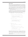
Put_DAC(DAC1,16383) ;Output 5V on DAC 1 signal
or
User1=16383
Put_PWM(PWM1,User1)
;a 50% pulse wave is output on Analog Output 1
Automate_DAC(2)
☞
This function is used to automatically update the DAC output voltage. This function
only needs to be called once. After this function is called, the DAC output will run
continuously. Note that in this function, the output value must be a variable.
Parameters
DAC#
Variable
Identifies which DAC channel is to be read (DAC1 or DAC2).
The variable that holds the desired output voltage;
the scale is 0–32767 = 0.0–10.0 volts.
Returns
0 – Setup did not execute.
1 – Setup successful.
Error Codes
Example
Bad_ID
Incorrect DAC ID was used.
PT_Range The variable used is not acceptable.
User1=0
Automate_DAC(DAC1,User1)
Loop:
User1=User1+1
;this will create a 0–10V ramp wave on DAC1
If User1=32767
{
User1=0
}
;add some delay or code here
Goto Loop
Curtis 1310 Manual, Rev. B
31
5 — VCL
Digital outputs
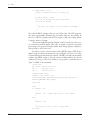
Put_PWM(2)
This function outputs an Pulse Width Modulated voltage on the selected output
pin. This function is used to control the state of the active low output FET drivers.
A value of 0 is Off (the output is open). A value of 32767 is fully On (the output
is closed to ground). Intermediate values provide a pulse train. A value of 16383
provides a 50% output (square wave). This can be useful to provide “average”
voltages and regulate current in an inductive load. A constant or a variable may
be used as the output value.
Parameters
PWM#
Value
Identifies which PWM channel is to be read (PWM1–PWM16).
The digital value of the output voltage;
the scale is 0–32767 = 0–100% On (switched to ground).
Returns
0 – New value did not go out.
1 – New value output on DAC.
Error Codes
Examples
Bad_ID
Incorrect PWM ID was used.
Auto_Run Trying to access an automated PWM
is not allowed.
Put_PWM(PWM1,16383)
;a 50% pulse wave is output on Output 1
or
User1=16383
Put_PWM(PWM1,User1)
;a 50% pulse wave is output on Output 1
32
Curtis 1310 Manual, Rev. B
5 — VCL
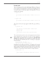
Automate_PWM(2)
☞
This function is used to automatically update the PWM output. This function only
needs to be called once. After this function is called, the PWM output will run continuously. Note that in this function, the output value must be a variable.
Parameters
PWM#
Variable
Identifies which PWM channel is to be read (PWM1–PWM16).
The variable that holds the desired output voltage;
the scale is 0–32767 = 0–100% On.
Returns
0 – Setup did not execute.
1 – Setup successful.
Error Codes
Example
Bad_ID
Incorrect PWM ID was used.
PT_Range The variable used is not acceptable.
User1=0
Automate_PWM(PWM1,User1)
Loop:
User1=User1+1
;this will create a 0–100% PWM ramp on Output 1
If User1=32767
{
User1=0
}
;add some delay or code here
Goto Loop
Curtis 1310 Manual, Rev. B
33
5 — VCL
Encoder outputs
There are two quadrature encoder inputs. These inputs can detect direction, position, and velocity from a pulse train of two channels, offset 90 degrees from each
other. Each encoder input must first be set up for use as a position counter or
as a velocity measurement. After the encoders are set up, the VCL uses special
functions to retrieve the count or velocity (in RPM) of the incoming pulse train. The
setup also allows enabling error detection.
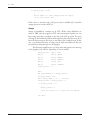
Setup_Encoder(4)
VCL must set up the encoders before they can be used. The Setup_Encoder
function sets the mode, conversion factor, and error detection parameters for the
encoder VCL functions.
Parameters
Enc#
Identifies which encoder is to be read (ENC1 or ENC2).
Mode
Sets the encoder to Velocity or Count mode, using the
predefined constant ENC_COUNT or ENC_VELOCITY.
Max_PPR
Sets either the Pulses Per Revolution or the maximum pulse
error count.
If the mode is ENC_VELOCITY, the value sets the pulses
that are seen in one revolution of the encoder; used to convert to RPM.
If the mode is ENC_COUNT, the value sets the number of
counts on Channel A that can be tolerated without a count
on Channel B before an error is declared; a setting of 0
disables error checking.
Max_Time Sets the time limit within which the count error (in Max_PPR)
must be reached for an error to be declared. This parameter
is used only in ENC_COUNT mode. Setting Max_Time to 0
means there is no time limit. Time limit = Max_Time × 16ms.
Returns
0 – Setup did not execute.
1 – Setup successful.
Error Codes
Examples
Bad_ID
Incorrect ENC ID was used.
Setup_Encoder(ENC1,ENC_VELOCITY,64,0)
;velocity mode where 64 pulses = 1 revolution
;note the last parameter is don’t care,
;but must be filled with some value.
Setup_Encoder(ENC2,ENC_COUNT,10,10)
;count mode
;if more than 10 counts on one channel without
;any on the other in under 160ms = Error!
34
Curtis 1310 Manual, Rev. B
5 — VCL
Get_Encoder_Count(1)
This function retrieves the current position (count) of the encoder. Note that this
function is not required to get the current count as it is continuously updated in the
ENC#_Count variable.
Data Values
ENC#_Count Variable that is updated with the value of the encoder count.
Parameters
Enc#
Identifies which encoder is to be read (ENC1 or ENC2).
Returns
N – Encoder count (0–32767).
Error Codes
Examples
Bad_ID
Incorrect ENC ID was used.
User1=Get_Encoder_Count(ENC1)
or
User1=ENC1_Count
Get_Encoder_Vel(1)
This function retrieves the current velocity (RPM) of the encoder. The output is the
speed in Revolutions Per Minute as scaled by the Setup_Encoder() function. Note
that this function is not required to get the current velocity as it is continuously
updated in the ENC#_Vel variable.
Data Values
ENC#_Vel Variable that is updated with the encoder velocity in RPM.
Parameters
Enc#
Identifies which encoder is to be read (ENC1 or ENC2).
Returns
N – Encoder velocity (0–32767).
Error Codes
Examples
Bad_ID
Incorrect ENC ID was used.
User1=Get_Encoder_Vel(ENC1)
or
User1=ENC1_Vel
Curtis 1310 Manual, Rev. B
35
5 — VCL
Get_Encoder_Dir(1)
This function retrieves the current direction (CW or CCW) of the encoder. Note that
this function is not required to get the current direction as it is continuously updated
in the ENC#_Dir variable. However, if the encoder speed (ENC#_Vel ) is zero, the
direction signal is not valid.
Data Values
ENC#_Dir Variable that is updated with the value of the encoder count.
Parameters
Enc#
Identifies which encoder is to be read (ENC1 or ENC2).
Returns
Encoder direction:
0 = stopped
1 = reverse
2 = forward
Error Codes
Examples
Bad_ID
Incorrect ENC ID was used.
User1=Get_Encoder_Dir(ENC1)
or
User1=ENC1_Dir
Get_Encoder_Error(1)
This function retrieves the current error status of the encoder. Note that this function is not required to get the current status as it is continuously updated in the
ENC#_Error variable.
Data Values
ENC#_Error Variable that is updated with the value of the encoder channel.
Parameters
Enc#
Identifies which encoder is to be read (ENC1 or ENC2).
Returns
Error status:
0 = OK
1 = Channel A error
2 = Channel B error
Error Codes
Examples
Bad_ID
Incorrect ENC ID was used.
User1=Get_Encoder_Error(ENC1)
or
User1=ENC1_Error
36
Curtis 1310 Manual, Rev. B
5 — VCL
Real-Time Clock (RTC)
The 1310 controller contains a real-time clock with battery backup. The clock
keeps accurate date and time for use by VCL (time stamping errors, clock display,
timed events, etc). When first used, the RTC may need to be updated. If so, the
RTC_Needs_Update variable will be set. The Setup_RTC function can be used to
set the day and time.
If the RTC stops working, the battery may need to be replaced; it should
last for many years. Open the end cap (the one with the LED status window) by
removing the six screws. Slide out the button Lithium battery. Replace the battery
and end cap. You will need to run a VCL program to update the RTC time and day
parameters. See the example following.
After it is set, the RTC continuously updates the following variables:
Hours_24
Hours_12
Am_Pm
Minutes
Seconds
Day
Month
Year
Day_of_Week
Actual Hour in 24h format (0...23)
Actual Hour in 12h format (1...12)
0 => AM, 1 => PM
Actual Minute (0...59)
Actual Seconds (0...59)
Actual Day (1...31)
Actual Month (1...12)
Year (00...99)
Actual Day of Week (MONDAY...SUNDAY).*
A few other variables of importance when using the RTC
RTC_Needs_Update
RTC_Disabled
Set to 1 when the RTC has to be updated
Set to 1 when RTC is disabled.
* When setting up the RTC or reading the Day_of_Week variable, VCL must use
the predefined constants:
MONDAY
TUESDAY
WEDNESDAY
THURSDAY
FRIDAY
SATURDAY
SUNDAY
Curtis 1310 Manual, Rev. B
37
5 — VCL
Setup_RTC(7)
This function sets up the date and time on the Real-Time Clock. Note that the
24-hour format must be used to set the time.
Parameters
Hours
Minutes
Seconds
Day
Month
Year
DayofWeek
Actual Hour in 24h format (0...23)
Actual Minute (0...59)
Actual Seconds (0...59)
Actual Day (1...31)
Actual Month (1...12)
Year (00...99)
Actual Day of Week (MONDAY...SUNDAY).
Returns
0 – Setup did not execute.
1 – Setup successful.
Error Codes
Examples
Param_Range
A parameter is out of range.
If(RTC_Needs_Update=1)
{
Setup_RTC(14,35,00,11,6,12,MONDAY)
;June 11, 2012 at 2:35:00pm
}
Hold_RTC(0) and Release_RTC(0)
These functions stop and start the updating of the Date and Time variables. Note
that the internal clock continues to run independent of these functions; only the
VCL variables are not updated after a Hold_RTC is called. This can be useful when
writing the time out to a display or time stamping a fault into EEPROM, as the time
will not tick forward unexpectedly during the process.
Use Release_RTC() to allow the automatic update of the the correct time and date
VCL variables to continue.
Hold_RTC() will set the RTC_Disabled variable (=1) and Release_RTC() will clear
it (=0)
These functions have no parameters and no errors, and return nothing.
Examples
Hold_RTC()
Release_RTC()
38
Curtis 1310 Manual, Rev. B
5 — VCL
UNIQUE I/O & VCL USAGE
The Curtis 1310 Vehicle System Controller is designed to be extremely flexible,
which means there is really no “standard configuration” or “standard wiring.”
Because of its wide ranging application and large array of inputs and outputs,
many features and possible uses of the 1310 may not be readily apparent. This
section will introduce the unique features and uses of some of the 1310’s I/O
and associated VCL. Examples cover such concepts as:
• Switch input usage with rising and falling edge detection
(interfacing to push buttons)
• Output 1 & 2 used as current source drivers
(interfacing to proportioning valves)
• Using arrays of text in VCL
(advanced interfacing to the Spyglass)
• Single channel pulse/frequency counters
• Sensor fault detection (using the measured voltage and load
on +5 and +12V).
I/O CONTROL WITH VCL
Digital Inputs
The 1310 controller can have up to 26 digital inputs; see the model selection
chart in Appendix D.
18 switch-to-B+ inputs (SW_1 through SW_18); sensed ON when switched
to B+ and OFF when left open.
8 switch-to-ground inputs (SW_19 though SW_26).
SW_19 – SW_22 will be sensed ON when left open and OFF when
switched to ground.
SW_23 – SW_26 are associated with the encoders and are sensed ON
when closed to ground and OFF when left open.
☞
To address a digital input in a VCL program, use the desired input label (SW_1
through SW_26). You must use the predefined constants ON or OFF in
the code when determining a switch state; using true/false or 1/0 will give erroneous results.
If (SW_1 = ON)
{
;put code here to run when switch 1 is On
}
If (SW_16 = OFF)
{
;put code here to run when switch 16 is Off
}
Curtis 1310 Manual, Rev. B
39
5 — VCL
All switch inputs are automatically debounced by the VCL operating system.
This prevents noisy contacts or contact bounce from causing erroneous events
in your VCL code. The debounce time can be varied from 0 to 32 milliseconds
in 4ms steps, using this function:
Setup_Switches(5); 20 milliseconds
If this line is not in the VCL code, the default debounce time is set at 16 ms.
The previous example “polls” the switch inputs at the the time the statement VCL is run. If there is a need to read fast inputs, the VCL will need to
poll these inputs very often in order not to miss a correct reading. Sometimes
it is not possible to run the VCL fast enough. Big programs or push buttons
cause the switch state to be easily missed.
SW_#_UP and SW_#_DOWN variables (where # = 1 through 26) give
VCL a better way to catch fast transients on the inputs. The “up” and “down”
terms are based on the action of a pushbutton that is pushed down to turn
something “on.” The 1310 samples the switch states 250 times per second.
Any input that has changed state from Off to On will set the corresponding
SW_#_DOWN variable. Any switch that has changed state from On to Off will
set the corresponding SW_#_UP variable. It is vital to note that once the bit is
set, it is not cleared by the corresponding variable. An input going off (released)
will not clear the SW_#_DOWN bit and likewise a switch being pushed down
(on) will not clear the SW_#_UP bit. It is this feature that allows the VCL code
to run less often and still detect input changes, even after the event occurs.
Once the VCL code has detected the change, it can clear the bit to allow the
next detection. The example below illustrates a push button interface.
If (SW_1_UP = ON)
{
;put code here to run when switch 1 is OFF (up & released)
SW_1_UP = OFF
;clear the bit so we can detect the button release
}
If (SW_1_DOWN = ON)
{
;put code here to run when switch 1 is ON (down & pressed)
SW_1_DOWN = OFF
;clear the bit so we can detect the next button press
}
Note that these bits are always checked to be ON, even for the switch off state.
Think of it not as the state of the input, but as the transition of the input.
In the first line, the VCL checks to see if it is true that the button went Off
(up). Normally, software is written to clear it (OFF) after reading it so that
the next state can be caught. Also note that it is entirely possible that both the
SW_#_UP and SW_#_DOWN bits are set. This simply means that the input
went both On and Off within the time it took for the VCL code to return to
these lines of code.
40
Curtis 1310 Manual, Rev. B
5 — VCL
Digital Outputs
All 16 outputs on the 1310 are Pulse Width Modulated active low FET drivers.
They are not simply turned On or Off but must be set to a duty cycle between
0% and 100%. Setting the PWM value to 0 will turn the output off completely
(open output) while a setting of 32767 will set it completely on (always pulled
to B-). A setting of 16383 provides nearly 50% duty cycle. The Put_PWM
and Automate_PWM functions are used for all digital outputs. The variable
PWM#_Output (where # is 1 through 16) can be used by VCL to read the
present state of any output driver.
Each output also has an associated input. This input goes on and off with
the PWM and senses the actual state of the FET driver and wiring. Using the
input function on an output can allow the wiring of a circuit to be fault checked.
Using the wiring configuration shown in Fig. 3, the Aux Contactor on Output 2
can be checked for proper connection before and after engaging it.
If (PWM2_Output = 0)
;check if Aux Contactor is open (off)
{
If (SW_2 = ON) ; check if the input is high
{
;the PWM is off and B+ is getting to the pin,
;so the coil must be connected
Put_PWM(PWM2, 32767) ;close the Aux Contactor
}
Else ;there is a fault!
{
;the input sense was low, so the coil
;must be disconnected or open.
;put your fault detect code HERE....
}
}
If (PWM2_Output = 32767)
;check if the Aux Contactor is closed (on)
{
If (SW_2 = ON)
;the input should be low, check if it is high
{
;the PWM is full on but B+ is getting to the pin,
;so the driver is bad
;put your bad FET driver code HERE
}
}
Because in this example the Aux Contactor is on Output 2, the VCL code can
check that the coil, once turned on, draws a reasonable current. If you look
at Table 2 on page 7, you will see that the raw value of this current reading
is put into ADC16_Output. The next example extends the fault checking to
include this feature.
Curtis 1310 Manual, Rev. B
41
5 — VCL
If (PWM2_Output = 32767)
;check if the Aux Contactor is closed (on)
{
If (ADC16_Output < 1000)
;the coil is drawing less than the minimum
;raw current reading
{
;put your low current coil fault detect code HERE...
}
}
Note that all ADC#_Output values are raw 10 bit value. The VCL programmer must experientially determine the reasonable values for this reading. In
the case of ADC15_Output and ADC16_output, a full scale reading (1024)
is equal to about 3.33 amps.
The current feedback signal in Outputs 1 and 2 can also be used to create a current-controlled output. This type of output is useful for accurately
positioning a flow proportional valve. In the basic wiring diagram, Output1 is
shown wired to such a valve coil.
In order to create a constant current with a PWM output, a PID loop is
added, using the current measurement as the feedback (see Section 14 of the
Common Functions manual for more detail). The PID controller automatically
regulates the PWM output so that the current reading matches the current
command. To keep a valve from sticking in one position, a small amount of
“jitter” is added to the command.
;setup code
Kp = 16767 ;Proportional gain
Ki = 2
;Integral gain
Kd = 0
;Derivative gain
Command equals User1
Command = 300 ;about 1 amp
Automate_PID(PID1,@Command,@ADC16_Output,@Kp,@Ki,@Kd,1,1)
Automate_PWM(PWM1,PID1_Output)
;Main Loop
Main:
If Command = 300
{
Command = 305
;adding some jitter to the command
}
Else
{
Command = 300
}
;add some more code or force a delay HERE
Goto Main
42
Curtis 1310 Manual, Rev. B
5 — VCL
Encoder Inputs
The encoder inputs can also be used as digital inputs. Pulling any of these pins
down to ground will cause the input to turn Off. Leaving it open will cause
it to be read On, as internally these 4 encoder inputs are pulled high to 5V.
Care must be taken not connect these inputs to any voltage above 5.5V or the
controller may be damaged.
If (SW_23 = ON)
{
;put code here to run when encoder 1 channel A (J4-1) is On
}
If (SW_24 = OFF)
{
;put code here to run when encoder 1 channel B (J4-2) is Off
}
These inputs also have the edge triggered variables SW_#_up and SW_#_
Down.
If (SW_23_Up = ON)
{
;put code here to run when encoder 1 channel A goes
;from On to Off
SW_23_Up = OFF
;clear the bit so VCL can read it next time around.
}
☞
The encoder channels can also be used to read a single pulse train. In the basic
wiring configuration, Fig. 3, this can be seen on J4-3, encoder 2 channel A.
When using the Setup_Encoder function, it is important to turn off any fault
checking. The normal ENC#_Count and ENC#_Vel variables will be valid.
Note that ENC#_Dir and ENC#_Error have no meaning in a single pulse
train measurement.
Setup_Encoder(ENC2, ENC_COUNT, 0, 0)
;count mode with error checking turned off
Normally, the encoder will be powered by the +5 volt supply on J4-15 (ground
is J4-16). The current leaving this pin is measured and placed in the variable
ADC11_Output. Checking the actual values against a known nominal value
will allow the VCL to catch a disconnected encoder/sensor (current is too low
on ADC11) or a short/excessive current (current is too high on ADC11).
If (ADC11_Output < 10)
{
;Error! encoder is disconnected, current draw is too low
}
Curtis 1310 Manual, Rev. B
43
5 — VCL
If (ADC11_Output > 1000)
{
;Error! There is a short dragging down the supply
;or too much current draw.
}
If the sensor or encoder needs +12V power, that is available at J3-4 and the
output current is sensed at ADC-12.
Arrays
Strings are handled in a unique way in VCL. All the string definitions are
taken in THE order they appear in VCL and concatenated together into one
large string array that is attached to the end of the VCL program. The array
of strings is then indirectly addressed through their index into the array. If we
know the first message in the array, we can index off it to find the next. In this
way, a one dimensional array of strings can be made and addressed. This can
be useful in creating messages for the Spyglass.
The following example creates a 5-string array and outputs a new message
to the Spyglass every 500 ms, depending on a user variable.
Display_Offset
equals
User1
MSG_01
string
“HELLO”
MSG_02
string
“ARRAYS”
MSG_03
string
“WITHIN”
MSG_04
string
“VCL”
MSG_05
string
“STRINGS”
Display_Offset = 0
Main:
Put_Spy_Text(MSG_01 + Display_Offset)
setup_delay(DLY2, 500)
while (DLY2_Output <> 0) {} ; 500 msec
Display_Offset = Display_Offset + 1
If (Display_Offset = 5)
{
Display_Offset = 0
;reset the offset if it is past the last message
}
goto Main
44
Curtis 1310 Manual, Rev. B
6 — DIAGNOSTICS & TROUBLESHOOTING
6
DIAGNOSTICS AND TROUBLESHOOTING
The following errors will be returned if VCL encounters a runtime error while
running one of its internal library functions. The error code consists of the
ID of the module where the error occurred and a Returned Error Value. The
Module ID can be found in the variable Last_VCL_Error_Module. The Error
Value is held in the variable Last_VCL_Error.
When an error occurs, its code is automatically sent out over the serial
port in Spyglass format. The format is EV VCL Module Value – Returned Error
Value; e.g., EV55-01 means Error VCL DAC Module Bad ID.
The VCL Module Values and Returned Error Values are listed in Tables
6 and 7.
Table 6 VCL Module IDs
Curtis 1310 Manual, Rev. B
VCL MODULE
VALUE
DESCRIPTION
MOD_CAN
01
Routines for CAN Bus
MOD_MAP
02
Routines for Mapping
MOD_VCL
03
Run-Time Interpreter
MOD_RMP
04
Routines for Ramping
MOD_SEL
05
Routines for Input Selectors
MOD_DLY
06
Routines for Delays
MOD_LIM
07
Routines for Limits
MOD_SCL
08
Routines for Scaling
MOD_CPY
09
Routines for Copying Objects
MOD_NVM
10
Routines for Non_Volatile Memory Access
MOD_PID
12
Routines for PID Control
MOD_TMR
13
Routines for Timers
MOD_ABS
14
Routines for Absolute Value Functions
MOD_ASP
15
Routines for Asynchronous Serial I/O
MOD_SYS
16
Routines for System Level Functions
MOD_FLT
17
Routines for Filtering
MOD_PAR
18
Routines for Non_Volatile Parameter Access
MOD_SPY
19
Routines for Spyglass
MOD_MTD
21
Routines for Multiply then Divide fucntion
MOD_ESP
23
Routines for Extended Serial Protocol Processing
MOD_ADC
50
Routines for Analog Inputs
MOD_POT
51
Routines for Pot Inputs
MOD_ENC
52
Routines to Read Encoder Inputs
MOD_PWM
53
Routines for PWM Outputs
MOD_SWI
54
Routines for Binary Switch Inputs
MOD_DAC
55
Routines for Analog Outputs
MOD_RTC
56
Routines for Real Time Clock
45
6 — DIAGNOSTICS & TROUBLESHOOTING
Table 7
RETURNED ERROR
46
VALUE
Returned Errors
DESCRIPTION
BAD_ID
01
Bad Index (device ID)
PT_RANGE
02
Variable Table Access out of range
AUTO_RUN
03
Attempt to access element running automatically
UNIT_UNDEF
04
Element accessed before being set up
PARAM_RANGE
05
Parameter is out of range
UNIT_BUSY
06
Unit is already busy
NO_FLASH_BLOCK
07
Could not find the specified flash block
FLASH_CHECKSUM
08
Flash block checksum is bad
TASK_OVR_RUN
09
Task queue overrun
NO_INIT
10
Tried to execute before initialization
CMD_END
11
Found end of table command
BAD_ENDIF
12
Bad End If location
CALL_OVF
13
Too many call statements
CALL_UNF
14
Too many return statements
OP_BAD
15
Undefined op-code
OP_UNKN
16
Unknown op-code
FUNC_IND
17
Function index is out of range
VAR_IND
18
Variable index is out of range
EVAL_OVF
19
Evaluation stack overflow
EVAL_UNF
20
Evaluation stack underflow
RESULT_OVF
21
Result stack overflow
RESULT_UNF
22
Result stack underflow
LOW_IPMS
23
Not enough instructions per millisecond
BAD_BAUD
30
Bad CAN Baud Rate
BAD_MO_ID
31
Bad Mailbox ID
BAD_MO_LEN
32
Bad Mailbox Length parameter
MO_INACTIVE
33
Attempt to access an inactive mailbox
MO_SENDING
34
Resending a message before old one sent
MO15_XMIT
35
Attempt to set mailbox to transmit
TYPE_UNDEF
40
Accessed a limit block with an undefined type
TYPE_SETUP
41
Accessed a limit block with a bad type specifier
TYPE_RUN
42
Bad type specifier in limit block while running
BAD_EEADD
43
EEPROM address is out of range
BAD_DEFAULTS
44
Parameter block default values are not up to date
PARAM_RO
45
Tried to write to a Read-Only parameter
BAD_P_TYPE
50
Pot Type out of range
ENC_PHASE
51
Encoder phase error
Curtis 1310 Manual, Rev. B
6 — DIAGNOSTICS & TROUBLESHOOTING
Note: All the VCL faults share LED fault code 68. The controller’s two
LEDs will display this repeating pattern:
RED
Curtis 1310 Manual, Rev. B
✱
(first digit)
YELLOW
RED
YELLOW
✲✲✲✲✲✲
✱✱
✲✲✲✲✲✲✲✲
(6)
(second digit)
(8)
47
7 — MAINTENANCE
7
MAINTENANCE
The Real-Time Clock battery is the only user serviceable part in Curtis 1310
controller. This battery is accessed from the rear panel (with the label and Status LEDs.) No attempt should be made to open the front panel, remove
the PCB, or otherwise modify the controller. Doing so may damage the
controller and will void the warranty. Carefully follow the procedure below to
replace the RTC battery.
It is recommended that the controller and connections be kept clean and
dry and that the controller’s fault history file be checked and cleared periodically.
CLEANING
☞
C AU T I O N
Periodically cleaning the controller exterior will help protect it against corrosion
and possible electrical control problems created by dirt, grime, and chemicals
that are part of the operating environment and that normally exist in battery
powered systems.
When working around any battery powered system, proper safety
precautions should be taken. These include, but are not limited to: proper
training, wearing eye protection, and avoiding loose clothing and jewelry.
Use the following cleaning procedure for routine maintenance. Never use
a high pressure washer to clean the controller.
1. Remove power by disconnecting the battery.
2. Discharge the capacitors in the controller by connecting a load
(such as a contactor coil) across the controller’s B+ and B- power
tabs.
3. Remove any dirt or corrosion from the power and signal
connector areas. The controller should be wiped clean with a
moist rag. Dry it before reconnecting the battery.
4. Make sure the connections are tight and plugs are seated and
latched.
FAULT HISTORY
The 1311 programmer can be used to access the controller’s fault history file.
The programmer will read out all the faults the controller has experienced
since the last time the fault history file was cleared. Faults such as contactor
faults may be the result of loose wires; contactor wiring should be carefully
checked. Faults such as overtemperature may be caused by operator habits or
by overloading.
After a problem has been diagnosed and corrected, it is a good idea to
clear the fault history file. This allows the controller to accumulate a new file
of faults. By checking the new fault history file at a later date, you can readily
determine whether the problem was indeed fixed.
48
Curtis 1310 Manual, Rev. B
7 — MAINTENANCE
REPLACING THE RTC BATTERY
It is not likely that you will need to replace the RTC battery as it is designed
to last 10+ years. But if the RTC has stopped functioning, the battery may be
dead.
1. Remove the six Phillips head screws on the rear panel (the panel with
the Status LEDs).
2. Carefully slide out the battery, noting the polarity.
3. Replace with an identical lithium battery, taking care of the proper
polarity.
4. Replace rear panel, noting the Status LEDs are on the lower right.
5. Replace the six Phillips screws. You may need to press lightly on the
bottom center cover to align the lower screw holes.
Curtis 1310 Manual, Rev. B
49
APPENDIX A: EMC & ESD DESIGN CONSIDERATIONS
APPENDIX A
VEHICLE DESIGN CONSIDERATIONS
REGARDING ELECTROMAGNETIC COMPATIBILITY (EMC)
AND ELECTROSTATIC DISCHARGE (ESD)
ELECTROMAGNETIC COMPATIBILITY (EMC)
Electromagnetic compatibility (EMC) encompasses two areas: emissions and
immunity. Emissions are radio frequency (RF) energy generated by a product.
This energy has the potential to interfere with communications systems such
as radio, television, cellular phones, dispatching, aircraft, etc. Immunity is the
ability of a product to operate normally in the presence of RF energy. EMC
is ultimately a system design issue. Part of the EMC performance is designed
into or inherent in each component; another part is designed into or inherent
in end product characteristics such as shielding, wiring, and layout; and, finally,
a portion is a function of the interactions between all these parts. The design
techniques presented below can enhance EMC performance in products that
use Curtis control products.
Emissions
Signals with high frequency content can produce significant emissions if connected to a large enough radiating area (created by long wires spaced far apart).
PWM drivers can contribute to RF emissions. Pulse width modulated square
waves with fast rise and fall times are rich in harmonics. (Note: PWM drivers at 100% do not contribute to emissions.) The impact of these switching
waveforms can be minimized by making the wires from the controller to the
load as short as possible and by placing the load drive and return wires near
each other.
For applications requiring very low emissions, the solution may involve
enclosing the system, interconnect wires and loads together in one shielded
box. Emissions can also couple to battery supply leads and circuit wires outside the box, so ferrite beads near the controller may also be required on these
unshielded wires in some applications. It is best to keep the noisy signals as far
as possible from sensitive wires.
Immunity
Immunity to radiated electric fields can be improved either by reducing overall
circuit sensitivity or by keeping undesired signals away from this circuitry. The
controller circuitry itself cannot be made less sensitive, since it must accurately
detect and process low level signals from sensors such as the throttle potentiometer. Thus immunity is generally achieved by preventing the external RF
energy from coupling into sensitive circuitry. This RF energy can get into the
controller circuitry via conducted paths and radiated paths. Conducted paths
are created by the wires connected to the controller. These wires act as antennas
and the amount of RF energy coupled into them is generally proportional to
A-1
Curtis 1310 Manual, Rev. B
APPENDIX A: EMC & ESD DESIGN CONSIDERATIONS
their length. The RF voltages and currents induced in each wire are applied to
the controller pin to which the wire is connected.
The Curtis 1310 includes bypass capacitors on the printed circuit board’s
sensitive input signals to reduce the impact of this RF energy on the internal
circuitry. In some applications, additional filtering in the form of ferrite beads
may also be required on various wires to achieve desired performance levels. A
full metal enclosure can also improve immunity by shielding the 1310 from
outside RF energy.
ELECTROSTATIC DISCHARGE (ESD)
Curtis products, like most modern electronic devices, contain ESD-sensitive
components, and it is therefore necessary to protect them from ESD (electrostatic
discharge) damage. Most of the product’s signal connections have protection
for moderate ESD events, but must be protected from damage if higher levels
exist in a particular application.
ESD immunity is achieved either by providing sufficient distance between conductors and the ESD source so that a discharge will not occur, or by
providing an intentional path for the discharge current such that the circuit
is isolated from the electric and magnetic fields produced by the discharge. In
general the guidelines presented above for increasing radiated immunity will
also provide increased ESD immunity.
It is usually easier to prevent the discharge from occurring than to divert
the current path. A fundamental technique for ESD prevention is to provide
adequately thick insulation between all metal conductors and the outside environment so that the voltage gradient does not exceed the threshold required for
a discharge to occur. If the current diversion approach is used, all exposed metal
components must be grounded. The shielded enclosure, if properly grounded,
can be used to divert the discharge current; it should be noted that the location of holes and seams can have a significant impact on ESD suppression. If
the enclosure is not grounded, the path of the discharge current becomes more
complex and less predictable, especially if holes and seams are involved. Some
experimentation may be required to optimize the selection and placement of
holes, wires, and grounding paths. Careful attention must be paid to the control
panel design so that it can tolerate a static discharge. MOV, transorbs, or other
devices can be placed between B¬and offending wires, plates, and touch points
if ESD shock cannot be otherwise avoided.
Curtis 1310 Manual, Rev. B
A-2
APPENDIX B: PROGRAMMER OPERATION
APPENDIX B
PROGRAMMERS
Curtis programmers provide programming, diagnostic, and test capabilities
for 1310 controllers. The power for operating the programmer is supplied by
the host controller via a 4-pin connector. Two programmers are available: the
PC Programming Station (1314) and the handheld programmer (1311). The
Programming Station has features not available on the handheld unit; on the
other hand, the handheld programmer has the advantage of being more portable.
Typically the Programming Station is used to set up the parameters initially and
the handheld programmer is used to made adjustments in the field.
Multiple versions of the programmers are available, each of which can
adjust the parameters at its own access level and below. A Dealer programmer,
for example, can adjust all the Dealer, Service and User-access parameters, but
not the OEM-access parameters.
HANDHELD PROGRAMMER (1311)
The 1311 programmer is easy to use, with self-explanatory functions. After
plugging in the programmer, wait a few seconds for it to boot up and gather
Fig. B-1 Curtis 1311
handheld programmer.
Curtis 1310 Manual, Rev. B
B-1
APPENDIX B: PROGRAMMER OPERATION
information from the controller. For experimenting with settings, the programmer can be left plugged in while the vehicle is driven.
The bookmark keys can make parameter adjustment more convenient.
To set a bookmark, press one of the three bookmark keys for more than two
seconds. To jump to a bookmarked location, press the appropriate bookmark
key quickly (for less than two seconds). For example, in setting the drive forward
throttle parameters, you might set a bookmark at the first of these parameters
[Program » Throttle » Forward Offset] and another at the raw throttle readout
[Monitor » Inputs » Throttle Pot]; this way you can easily toggle between the
readout and the parameters.
The bookmark keys also have another function that makes programming easier. When setting the value of a parameter, you can use these keys to
adjust the increments by which the value changes—with Bookmark Key 1, the
value changes in 10-digit steps up or down; with Bookmark Key 2 pressed,
the value changes in 100-digit steps; and with Bookmark Key 3, in 1000digit steps—which, for most parameters, takes you from the maximum to the
minimum, or vice versa.
PC PROGRAMMING STATION (1314)
The Programming Station is an MS-Windows 32-bit application that runs on a
standard Windows PC. It can do everything the handheld programmer can do,
and more. Its additional capabilities include saving/restoring sets of parameters
to/from disk and updating software. Instructions for using the Programming
Station are included with the software.
PROGRAMMER MENUS
The programmers have six menus, which in turn lead to nested submenus.
Program — provides access to the programmable parameters (see Section 3).
Monitor — presents real-time values during vehicle operation; these include
all inputs and outputs, as well as the mapped throttle values and conditioned
throttle requests (see Section 4a).
Faults — presents diagnostic information, and also a means to clear the fault
history file (see Section 6).
Functions — provides access to the controller-cloning commands and to the
“reset” command.
Information — displays data about the host controller: model and serial numbers,
date of manufacture, hardware and software revisions, and itemization of other
devices that may be associated with the controller’s operation.
Programmer Setup — displays data about the programmer: model and serial
numbers, and date of manufacture.
B-2
Curtis 1310 Manual, Rev. B
APPENDIX C: SPECIFICATIONS
APPENDIX C
SPECIFICATIONS
Table C-1
SPECIFICATIONS: 1310 CONTROLLER
Nominal input voltage
Electrical isolation to case
24–48 V
500 V ac (minimum)
Storage ambient temperature range
Operating ambient temperature range
-50°C to 90°C
-40°C to 85°C
Enclosure protection rating
IP42
Weight
0.82 kg
Dimensions (L× W×H)
198 × 138 × 46 mm
EMC Immunity
EMI Emissions
Safety
Enclosure Flammability Rating
Designed to meet EN 50082-2: 1995
Designed to meet EN 50081-1: 1992
Designed to meet EN 1175-1: 1998
Class UL 94-V0.
Note: Regulatory compliance of the complete vehicle system
with the controller installed is the responsibility of the OEM.
MODEL
NUMBER
NOMINAL
BATTERY VOLTAGE
OUTPUTS / INPUTS
OPTIONS
1310-5210
24–48 V
8 outputs / 18 inputs
a, b
1310-5310
24–48 V
16 outputs / 22 inputs
a, b
Real-Time Clock
Real-Time Clock, PV Drivers
c
Notes: a Encoder inputs can be used for an additional 4 inputs.
b Outputs 9–16 are available; Inputs 14, 15, and 17 are not available.
c PV (Proportional Valve) drivers are on Outputs 1 and 2, and have current feedback.
Curtis 1310 Manual, Rev. B
C-1