Download User`s Guide
Transcript
SUPER AOC-SIMLC AOC-SIMLC+ USER'S GUIDE Rev. 1.1 ® AOC-SIMLC/SIMLC+ User's Guide The information in this User’s Guide has been carefully reviewed and is believed to be accurate. The vendor assumes no responsibility for any inaccuracies that may be contained in this document, makes no commitment to update or to keep current the information in this user's guide, or to notify any person or organization of the updates. Please Note: For the most up-to-date version of this user's guide, please see our web site at www.supermicro.com. SUPERMICRO COMPUTER, INC. reserves the right to make changes to the product described in this user's guide at any time and without notice. This product, including software, if any, and documentation may not, in whole or in part, be copied, photocopied, reproduced, translated or reduced to any medium or machine without prior written consent. IN NO EVENT WILL SUPERMICRO COMPUTER BE LIABLE FOR DIRECT, INDIRECT, SPECIAL, INCIDENTAL, OR CONSEQUENTIAL DAMAGES ARISING FROM THE USE OR INABILITY TO USE THIS PRODUCT OR DOCUMENTATION, EVEN IF ADVISED OF THE POSSIBILITY OF SUCH DAMAGES. IN PARTICULAR, THE VENDOR SHALL NOT HAVE LIABILITY FOR ANY HARDWARE, SOFTWARE, OR DATA STORED OR USED WITH THE PRODUCT, INCLUDING THE COSTS OF REPAIRING, REPLACING, INTEGRATING, INSTALLING OR RECOVERING SUCH HARDWARE, SOFTWARE, OR DATA. Any disputes arising between manufacturer and customer shall be governed by the laws of Santa Clara County in the State of California, USA. The State of California, County of Santa Clara shall be the exclusive venue for the resolution of any such disputes. Supermicro's total liability for all claims will not exceed the price paid for the hardware product. WARNING: Handling of lead solder materials used in this product may expose you to lead, a chemical known to the State of California to cause birth defects and other reproductive harm. User's guide Revision: Rev. 1.1 Release Date: July 17, 2012 Unless you request and receive written permission from SUPER MICRO COMPUTER, Inc., you may not copy any part of this document. Information in this document is subject to change without notice. Other products and companies referred to herein are trademarks or registered trademarks of their respective companies or mark holders. Copyright © 2012 by SUPER MICRO COMPUTER, INC. All rights reserved. Printed in the United States of America 1-2 Chapter 1: Introduction Table of Contents Chapter I: Introduction .............................................................................1-4 1.1 Overview .................................................................................................... 1-4 1.2 IPMI Version 2.0 ........................................................................................ 1-5 1.3 Product Features ...................................................................................... 1-5 1.4 Checklist .................................................................................................... 1-5 1.5 Important Notes to the User .................................................................... 1-5 1.6 Contacting Supermicro ............................................................................ 1-6 &KDSWHU7HFKQLFDO6SHFL¿FDWLRQVDQG+DUGZDUH,QVWDOODWLRQ .......... 2-1 2.1 AOC-SIMLC/SIMLC+ Connector and Jumper Locations ...................... 2-1 2.1.1 Front Component and LED Descriptions ................................................ 2-1 2.1.2 Rear Component and LED Locations ..................................................... 2-2 5HDU/(''HVFULSWLRQVDQG3LQ'H¿QLWLRQV ............................................ 2-2 2.2 Block Diagram .......................................................................................... 2-3 2.3 Installing the AOC-SIMLC/SIMLC+ Add-On Card .................................. 2-4 2.3.1 Safety Guidelines .................................................................................... 2-4 2.3.2 SIMLC/SIMLC+ Slot Locations ................................................................ 2-5 Chapter 3: Software Application and Usage .......................................... 3-1 +RPH3DJH ................................................................................................ 3-3 )XQFWLRQV/LVWHG2QWKH+RPH3DJH ..................................................... 3-5 3.2.1 Remote Control ....................................................................................... 3-5 3.2.2 Virtual Media ............................................................................................ 3-7 3.2.3 System Health ........................................................................................3-11 3.2.4 User Management ................................................................................. 3-17 3.2.5 KVM Settings ......................................................................................... 3-21 3.2.6 Device Settings ...................................................................................... 3-25 3.2.7 Maintenance .......................................................................................... 3-38 3.3 Remote Console Main Page .................................................................. 3-42 3.3.1 Remote Console Options ...................................................................... 3-43 Chapter 4: Frequently Asked Questions ................................................ 4-1 1-3 AOC-SIMLC/SIMLC+ User's Guide Chapter 1 Introduction This user's guide is written for system integrators, PC technicians and knowledgeable PC users who intend to integrate Supermicro's unique IPMI 2.0 Management Utility with support of KVM-over-LAN into their systems. It provides detailed information for the application and use of the AOC-SIMLC/SIMLC+ that supports remote access for system monitoring, diagnosis and management. With the most advanced technologies built-in, the AOC-SIMLC/SIMLC+ offers a complete, ef¿FLHQWDQGFRVWHIIHFWLYHUHPRWHVHUYHUPDQDJHPHQW(See Note 1 on Page 1-5.) 1.1 Overview 7KH$2&6,0/&6,0/& LV D KLJKO\ HI¿FLHQW KLJKO\ FRPSDWLEOH DQG HDV\WRXVH IPMI card that allows the user to take advantage of the BMC, a baseboard management controller installed on a server motherboard, and the IPMIView, an IPMIcompliant management application software stored in a PC, to provide serial links between the main processor and other system components, allowing for network interfacing via remote access. With an independent KIRA100 processor built-in, the AOC-SIMLC/SIMLC+ provides the user with a solution to ease the complex and expensive systems, allowing an administrator to access, monitor, diagnose and manage network interfacing anywhere, anytime. 1.2 IPMI Version 2.0 The AOC-SIMLC/SIMLC+ supports the functionality of IPMI Version 2.0. The key features include the following: Supports IPMI 2.0 over LAN Supports Serial over LAN Supports KVM over LAN (See Note 1 on Page 1-5.) Supports Virtual Media over LAN Supports LAN Alerting-SNMP Trap Supports Event Log Offers OS (Operating System) Independency Provides remote Hardware Health Monitoring via IPMI. Key features include the following: Temperature monitoring Fan speed monitoring Voltage monitoring 1-4 Chapter 1: Introduction Power status monitoring, chassis intrusion monitoring Remote power control to power-on, power-off or reboot a system Remote access to text-based, graphic-based system information, LQFOXGLQJ%,26FRQ¿JXUDWLRQVDQG26RSHUDWLRQLQIRUPDWLRQ.90 (See the Note below.) Remote management of utility/software applications Provides Network Management Security via remote access/console redirection. Key features include: User authentication enhancement (QFU\SWLRQVXSSRUWHQKDQFHPHQWDOORZLQJIRUSDVVZRUGFRQ¿JXUDtion security to protect sensitive data transferring via Serial over LAN Supports the following Management tools: IPMIView, CLI (Command Line Interface) Supports RMCP & RMCP protocols 1.3. Product Features 6OLPVL]H:[+PP:[PP+ 6XSSRUWV,30,RYHU/$1 6XSSRUWV8DQGDERYH 1.4 Checklist If your shipping package came with missing or damaged parts, please contact Supermicro's Tech. Support. Please refer to the following checklist when contacting us. i. AOC-SIMLC/SIMLC+ ii. CDR-SIMIPMI: One Installation CD iii. White Box with Correct Barcode Label (showing AOC-SIMLC/SIMLC+). 1.5 Important Notes to the User Note 1: KVM-over-LAN is available on the AOC-SIMLC+ only. All features and options related to the functionality of KVM-over-LAN are supported by the AOCSIMLC+ only. In addition, KVM-over-LAN is not supported by the X7DA8/X7DAE, and the X7DVL-3/X7DVL-i models. Note 2: The graphics shown in this user's guide were based on the latest PCB Revision available at the time of publishing of this guide. The SIM1U-3B(+) card you’ve received may or may not look exactly the same as the graphics shown in this user's guide. 1-5 AOC-SIMLC/SIMLC+ User's Guide 1.6 Contacting Supermicro +HDGTXDUWHUV Address: Tel: Fax: Email: Web Site: SuperMicro Computer, Inc. 980 Rock Ave. San Jose, CA 95131 U.S.A. +1 (408) 503-8000 +1 (408) 503-8008 [email protected] (General Informaion) [email protected] (Technical Support) www.supermicro.com Europe Address: Tel: Fax: Email: SuperMicro Computer B.V. Het Sterrenbeeld 28, 5215 ML 's-Hertogenbosch, The Netherlands +31 (0) 73-6400390 +31 (0) 73-6416525 [email protected] (General Information) [email protected] (Technical Support) [email protected] (Customer Support) $VLD3DFL¿F Address: SuperMicro, Taiwan 4F, No. 232-1 Liancheng Road Chung-Ho Dist., New Taipei City 235 Taiwan, R.O.C. Tel: Fax: Web Site: +886-(2) 8226-3990 +886-(2) 8226-3991 www.supermicro.com.tw Email: [email protected] (Technical Support) Tel: +886-(2) 8226-5990 (Technical Support) 1-6 &KDSWHU7HFKQLFDO6SHFL¿FDWLRQVDQG,QVWDOODWLRQ Chapter 2 7HFKQLFDO6SHFL¿FDWLRQVDQG+DUGZDUH Installation 2.1 AOC-SIMLC/SIMLC+ Component and Jumper Locations Front View 1 V-RAM 2 SDRAM SDRAM 3 3 SIMLC (Note RU LQGLFDWHV3LQ 2.1.1 Front Component and LED Descriptions #1. D3: Standby Power LED Indicator When this LED is on, the standby power is on. Be sure to remove power cables before installing or removing components. #2. VRAM (64Mb/166MHz) #3. SDRAM (128Mb/133MHz) Note: KVM-over-LAN is available on the AOC-SIMLC+ only. All features and options related to the functionality of KVM-over-LAN are supported by the AOC-SIMLC+ only. In addition, KVM-over-LAN is not supported by the following motherboards: 1. The X7DA8/X7DAE, 2. The X7DVL-3/X7DVL-i 2-1 AOC-SIMLC/SIMLC+ User's Guide 2.1.2 Rear Component and LED Locations Rear View Kira 100 Processor 3 Heartbeat LED 1 Flash Memory 2 (Note RU LQGLFDWHV3LQ Rear Side Components 1. The (independent) Kira 100 Processor 2. Flash Memory 3. Heartbeat LED 5HDU/(''HVFULSWLRQDQG3LQ'H¿QLWLRQV +HDUWEHDW/(',QGLFDWRU Heartbeat LED (marked #3 above), located on the rear side of the AOCSIMLC(+) card, indicates the functionality and activity of the add-on card. The blinking of the Heartbeat LED indicates that the AOC-SIMLC(+) is active. However, when the Linux OS and the drivers are being loaded after each AC power-on or reset, the Heartbeat LED is off for about a minute. Then, the Heartbeat LED will be on again to indicate that the AOCSIMLC(+) is active. See the table on the right for details. 2-2 +HDUWEHDW/('' On (Blinking) SIMLC(+): active Off (for 1 minute) Loading Firmware Off (Continuously) SIMLC(+) is not active &KDSWHU7HFKQLFDO6SHFL¿FDWLRQVDQG,QVWDOODWLRQ 2.2 Block Diagram UART Interface USB Interface IPMI-200 Connector LPC Interface KIRA100 FML Interface DVO interface RMII Mother Board SMDATA Mother Board SMCLK Mother Board SMALT# 2-3 AOC-SIMLC/SIMLC+ User's Guide 2.3 Installing the AOC-SIMLC/SIMLC+ Add-On Card 2.3.1 Safety Guidelines To avoid personal injury and property damage, please carefully follow all the safety steps listed below when installing the AOC-SIMLC/SIMLC+ into your system. ESD Safety Guidelines Electro Static Discharge (ESD) can damage electronic components. To prevent damage to your system, it is important to handle it very carefully. The following measures are generally sufficient to protect your equipment from ESD. • Use a grounded wrist strap designed to prevent static discharge. • Touch a grounded metal object before removing a component from the antistatic bag. • Handle the add-on card by its edges only; do not touch its components, peripheral chips, memory modules or gold contacts. • When handling chips or modules, avoid touching their pins. • Put the card and peripherals back into their antistatic bags when not in use. General Safety Guidelines • Always disconnect power cables before installing or removing any components from the computer. • Use only the correct type of bracket for the add-on card. • Disconnect the power cable before removing any cable from the add-on card. • Make sure that the SIMLC/SIMLC+ add-on card is securely seated in the SIMLC/SIMLC+ slot to prevent damage to the system due to power shortage. For SIMLC/SIMLC+ slot locations, please refer to Section 2.4.2. SMC Motherboards with SIMLC/SIMLC+ support The following Supermicro's motherboards support the AOC-SIMLC/SIMLC+. 1. The X7DB8/X7DBE/X7DB8+/X7DBE+/X7DB8-X/X7DBE-X/X7DB3 Series 2. The X7DA8/X7DAE/X7DVA-8/X7DVA-E/X7DVL-3/X7DVL-i Series (Note) 3. The X7DVL-E Series (Note: KVM-over-LAN is not available on the X7DA8/X7DAE/X7DVL-3/X7DVL-i models.) 2-4 &KDSWHU7HFKQLFDO6SHFL¿FDWLRQVDQG,QVWDOODWLRQ 2.3.2 SIMLC/SIMLC+ Slot Locations To properly use the AOC-SIMLC/SIMLC+, be sure to install it in the right slot. Refer to the MB layouts below for SIMLC/SIMLC+ slot locations. 1. The X7DB8/X7DBE/X7DB8+/X7DBE+/X7DB8-X/X7DBE-X/X7DB3 Series SIMLC(+) Slot (Slot 7) 2. The X7DA8/X7DAE/X7DVA-8/X7DVA-E/X7DVL-3//X7DVL-i Series (Note) SIMLC(+) Slot (Slot 7) 3. The X7DVL-E Series SIMLC(+) Slot (JIPMI) (Note: KVM-over-LAN is not available on the X7DA8/X7DAE/X7DVL-3/X7DVL-i models.) 2-5 AOC-SIMLC/SIMLC+ User's Guide Notes 2-6 Chapter 3: Software Application and Usage Chapter 3 Software Application and Usage With an independent I/O processor embedded in Raritan's Kira 100 RISC System Chip, the AOC-SIMLC/SIMLC+ Add-On Card allows the user to access, monitor, manage and interface with systems that are in remote locations via LAN. (See the Note on Page 3-2.) 7KHQHFHVVDU\XWLOLWLHVIRUWKHDFFHVVDQGFRQ¿JXUDWLRQRIWKH add-on card are included on the Supermicro bootable CDs that came with your FDUG7KLVVHFWLRQSURYLGHVLQIRUPDWLRQRQWKHFRQ¿JXUDWLRQDQGWKHDFFHVVRIWKH IPMI card on the network. 8VLQJWKH,30,&)*8WLOLW\WR&RQ¿JXUH,30$&$GGUHVVHVDQGRWKHU IPMI Network Settings 1. Run the ipmicfg utility from the bootable CD that came with your shipment. 5HIHUWRWKHWDEOHEHORZWRFRQ¿JXUHWKH,30$&DGGUHVVHV Board IPMI MAC IP Communication through X7 Series SIMLC IPMI Card Availabl IP/DHCP LAN1 on MB H8 DDR2 Memory SIMLC IPMI Card Available IP/DHCP LAN1 on MB H8QM3/i-x (Note 2 below) SIMLC LAN1 LAN1 LAN1 on MB )ROORZWKHLQVWUXFWLRQVJLYHQLQWKH5HDGPHW[W¿OHWRFRQ¿JXUH*DWHZD\,31HWPDVN,3DGGUHVVHVWRHQDEOHGLVDEOH'+&3DQGWRFRQ¿JXUHRWKHU,30,VHWWLQJV Note17KH5HDGPHW[W¿OHLVLQFOXGHGLQWKH&'WKDWFDPHZLWK\RXUVKLSPHQW$ FRS\RIWKH5HDGPHW[W¿OHGDWHGLVDOVRLQFOXGHGEHORZ IPMICFG Version 1.04 Copyright 2007 SuperMicro Computer Inc. Usage: IPMICFG Parameters (Example: IPMICFG -m 192.168.1.123) -m Show IP and MAC -m IP Set IP (format: ###.###.###.###) -a MAC Set MAC (format: ##:##:##:##:##:##) -k Show Subnet Mask -k Mask Set Subnet Mask (format: ###.###.###.###) -dhcp on Enable the DHCP -dhcp off Disable the DHCP -g Show Gateway IP -g IP Set Gateway IP (format: ###.###.###.###) Note 2)RUWKH+40LWKH$2&6,0/&,30,FDUGKDVWRÀDVKWKH¿UPware bin from \Firmware\H8Qxx-x in the driver CD. If the AOC-SIMLC(+) IPMI card communicates through the onboard LAN1 on the H8QM3/i-2(+), you can only use the IPMIView Utility to access the AOC-SIMLC(+) IPMI card. 3-1 AOC-SIMLC/SIMLC+ User's Guide To Access the SIM1U/SIM1U+ Card from a Computer 1. Choose a computer that is connected to the same network and open the browser. 2. Type in the IP address of each server that you want to connect in the address bar in your browser. 3. Once the connection is made, the Log In screen as shown below displays. To Log In Once you are connected to the remote server, the following Log In screen displays. 7\SHLQ\RXU8VHUQDPHLQWKH8VHUQDPHER[ 7\SHLQ\RXU3DVVZRUGLQWKH3DVVZRUGER[DQGFOLFNRQ/RJLQ (Note: The default username is ADMIN. The default password is ADMIN.) 3. The Home Page will display as follows: Note: KVM-over-LAN is available on the AOC-SIMLC+ only. All features and options related to the functionality of KVM-over-LAN are supported by the AOC-SIMLC+ only. In addition, KVM-over-LAN is not supported by the following motherboards: 1. X7DA8/X7DAE 2. X7DVL-3/X7DVL-i 3-2 Chapter 3: Software Application and Usage +RPH3DJH Home Console Remote Console Screen Logout 4 2 Function Keys 1 9 3 5 6 7 8 %XWWRQVIURPWKH+RPH3DJH 1 +RPH: Click this icon to return to the Home Page. 2 Console: Click this icon to go to the Remote Console Screen. 3 Remote Console Screen: Displayed in the window is Remote Console Screen. Click on this window to go to the Remote Console Screen. 4 Logout: Click on this icon to log out. 5 Refresh: Click on this icon to refresh the screen of the remote console preview. 6 Power On: Click on this icon to power on the system of the remote host. 7 Power Down: Click on this icon to power down the system of the remote host. 8 Reset: Click on this icon to reset the remote host. 3-3 AOC-SIMLC/SIMLC+ User's Guide )XQFWLRQ.H\VIURPWKH+RPH3DJH 9 &OLFNRQWKHVHIXQFWLRQNH\VWRXVHWKHIXQFWLRQVDVVSHFL¿HGEHORZ 1 2 3 4 5 6 7 1. Remote Control: Click on this icon for remote access and management of Video Console Redirection. 2. Virtual Media: Click on this icon to use virtual remote media devices. 6\VWHP+HDOWK: Click on this icon to view and manage health monitoring for remote systems 4. User Management: Click on this icon for User Management. 5. KVM Settings &OLFN RQ WKLV LFRQ WR FRQ¿JXUH NH\board, Video and mouse settings. 6. Device Settings&OLFNRQWKLVLFRQWRFRQ¿JXUHGHYLFH settings. 7. Maintenance: Click on this icon to access, diagnose and manage hardware devices (Note3OHDVHVHHWKHQH[WSDJHIRUGHWDLOVRQWKHIXQFWLRQVVSHFL¿HGDERYH 3-4 Chapter 3: Software Application and Usage )XQFWLRQV/LVWHGRQWKH+RPH3DJH 3.2.1. Remote Control Click on the icon of Remote Control to activate its submenus-KVM Console and Remote Power as listed below. a. KVM Console (See the note on Page 3-1) &OLFN RQ WKLV LWHP WR FRQ¿JXUH NH\ERDUG PRXVH RU YLGHR VHWWLQJV IRU WKH UHPRWH host. Remote Console Screen 1 2 3 4 Explanation of Functions In the Single/Synchronized Mouse Mode, this cursor indicates the sys1 tem that is currently active. For the Double Mouse mode, this is the cursor for the remote host. 2 This second mouse cursor only appears in the Double Mouse Mode. This cursor represents the local mouse. 3 This icon indicates the availability of Keyboard and Mouse. 4 This icon indicates the number of networks (users) that are connected YLD&RQVROH5HGLUHFWLRQ7KHQXPEHURI¿JXUHLFRQVLQGLFDWHVWKHQXPber of users connected.) 3-5 AOC-SIMLC/SIMLC+ User's Guide b. Remote Power &OLFN RQ WKLV LWHP WR FRQ¿JXUH WKH SRZHU VHWWLQJV IRU 5HPRWH &RQVROH DV VKRZQ below. Remote Power Screen 1 2 3 Explanation of Functions 1 Power On: Click on this icon to power on the remote host. 2 Power Down: Click on this icon to power down the remote host. 3 Reset: Click on this icon to reset the remote host. 3-6 Chapter 3: Software Application and Usage 3.2.2. Virtual Media Click on the Virtual Media icon on the Home Page to activate its submenus-Floppy Disk, CD-ROM, Drive Redirection and Options as listed below. a. Floppy disk Floppy Disk Screen 2 3 1 4 5 6 7 Explanation of Functions Floppy Disk: Click on this function key to upload the data 1 VWRUHGLQWKHORFDOÀRSS\GLVNLPDJHWRWKHUHPRWHKRVW 2 Active Image (Drive1): This window displays the data that has been uploaded to Drive 1 of the remote host. 3 Active Image (Drive2): This window displays the data that has been uploaded to Drive 2 of the remote host. 4 Floppy Image Upload: This option allows the user to upORDG WKH ÀRSS\ LPDJH DV ÀRSS\ ORFDWHG LQ WKH UHPRWH KRVW 7KH ÀRSS\ LPDJH XSORDGHG VKDOO EH LQ WKH ELQDU\ format with a maximum size of 1.44MB. It will be loaded to the Supermicro SIMLC/SIMLC+ card and will be emulated to the host as a USB device. 5 Virtual Drive: Select a drive in the remote host as a destination drive for you to upload your image data. 6 7 Floppy Image File &OLFN RQ %URZVH WR SUHYLHZ DQG VHOHFW WKH ¿OHV WKDW \RX ZLVK WR XSORDG WR WKH KRVW GULYH selected. Upload2QFHWKHFRUUHFW¿OHQDPHDSSHDUVLQWKHER[ FOLFN8SORDGWRXSORDGWKHÀRSS\LPDJHWRWKHGULYHVSHFL¿HGLQWKHUHPRWHKRVW 3-7 AOC-SIMLC/SIMLC+ User's Guide b. CD-ROM Image CD-ROM Image Screen 2 3 1 4 5 6 7 8 9 10 Explanation of Functions 1 2 3 4 CD-ROM image: Click on this function key to share data stored in your local CD-ROM drive with other users in the remote host through the Windows Share application via USB. Active Image (Drive1) 7KLV ZLQGRZ GLVSOD\V WKH ¿OH name of the data currently active in host Drive 1. Active Image (Drive2) 7KLV ZLQGRZ GLVSOD\V WKH ¿OH name of the data currently active in host Drive 2. Image on Windows Share: This option allows the user to FRQ¿JXUH:LQGRZV6KDUHVHWWLQJV,WDOORZV\RXWRGHFLGH KRZ \RX ZDQW WR VKDUH WKH &'520,62 ,PDJH ¿OH ZLWK users in the remote host. 5 Virtual Drive: Specify the drive that you want to share your data with in the remote host. 6 6KDUH +RVW Key in the IP Address or the name of the system you wish to share data with via Windows Share. 7 Share Name: Key in the name of the system you wish to share data with in the remote host. 8 Path to Image:.H\LQWKHORFDWLRQRIVRXUFH¿OHVWKDW you wish to share via Windows Share. 9 User/Password (Optional): Key in the Username and password for the person to access the data that you want WRVKDUHDQGFOLFN6HWWRHQWHU\RXUVHOHFWLRQV 10 3-8 Chapter 3: Software Application and Usage c. Drive Redirection Drive Redirection Screen 2 3 1 4 5 6 7 8 Explanation of Functions Drive Redirection: Click on this function key to make lo1 cal drives accessible for other users via console redirection. This function allows you to share your local drives (Floppy, CD-ROM and HDDs) with users in the remote systems. 2 Active Image (Drive1) 7KLV ZLQGRZ GLVSOD\V WKH ¿OH name of the data currently active in host Drive 1. 3 Active Image (Drive2) 7KLV ZLQGRZ GLVSOD\V WKH ¿OH name of the data currently active in host Drive 2. 4 5 6 7 8 Drive Redirection 8VH WKLV ZLQGRZ WR FRQ¿JXUH 'ULYH Redirection settings. Disable Drive Redirection: Check the box to disable Drive Redirection. Once this function is disabled, local drives will not be accessible for other users in remote host. Force Read Only: Check this box to allow the data stored in local drives to be read in a remote system, but it cannot be overwritten to ensure data integrity and system security. Apply2QFH\RX YHFRQ¿JXUHG\RXUVHWWLQJVFOLFN$SSO\WRHQWHU\RXUVHWWLQJV Reset Default: You can also key in your own setting valXHV DQG UHVHW WKHVH YDOXHV DV GHIDXOW E\ FOLFNLQJ RQ this icon to reset the defaults. 3-9 AOC-SIMLC/SIMLC+ User's Guide d. Virtual Media Options Virtual Media Options Screen 2 4 1 Explanation of Functions 1 2 Options: Click on this function key to activate the Virtual Media sub-menu. Virtual Media Options: Use this option to disable or enable USB MASS storage in the remote host. Check this box to disable the function of Virtual Media Options to prevent data stored in a local drive from being accessed, or uploaded by the user in the remote host. The default VHWWLQJLVHQDEOHG 3 Apply2QFH\RX YHFKHFNHGWKHER[FOLFN$SSO\WRHQter this value. 4 Reset to Defaults,I\RXZDQWWRVHW'LVDEOHGDVWKH default setting for the item-Virtual Media Options, click on this icon. 3-10 Chapter 3: Software Application and Usage 6\VWHP+HDOWK Click on the System Health icon on the Home Page to activate its submenus: Chassis Control, Monitor Sensor, System Event Log and Alert settings as listed below. 6\VWHP+HDOWK6FUHHQ a. Chassis Control Chassis Control Screen 2 1 3 1 2 Chassis Control Chassis Control: Click on this function key to access Health Monitoring information on the remote chassis. The items monitored include 1. Chassis Information 2. Power Control. Chassis Information: The following remote chassis information is included: Power Is: This indicates if the system is on or off for the remote host. Power On Counter: If power is on, then the counter indicates the length of time the power has been turned on. Last Restart Cause: This item states the reason why the host system is restarted if the system has been turned off. Refresh &OLFN WKH 5HIUHVK EXWWRQ WR XSGDWH &KDVVLV ,QIRUPDWLRQ DV VKRZQ LQ Window 2. 3-11 AOC-SIMLC/SIMLC+ User's Guide 3 Power Control The following Power Control items are included: Refresh: Click on this icon to refresh the screen of the remote host. Power On: Click on this icon to power on the system for the remote host. Power Down: Click on this icon to power down the system for the remote host. Power Cycle: Click on this icon to power down the system for the remote host and turn it back on later. Reset: Click on this icon to reset the remote console. 3-12 Chapter 3: Software Application and Usage b. Monitor Sensors Monitor Sensors Screen 1 1 Monitoring Sensor: Click on this function key to display the following Health Monitoring Information shown in the following table: 3-13 AOC-SIMLC/SIMLC+ User's Guide Health Monitoring Sensor Information on the Remote Host Temperature Monitoring Voltage Monitoring Fan Control Physical Security Module/Board CPU0 Internal E. Module/Board CPU1 Internal E. Module/Board CPU Overheat CPU1 Temperature (Temp A, Temp B) CPU2 Temperature (Temp A, Temp B) System Temperature CPU1 VCore CPU2 VCore 3.3V 5V, 5VSB +12V, -12V 1.5V VBAT Fan1/CPU Fan Fan2/CPU Fan Fan 3 – Fan 6 Chassis Intrusion Temp A: CPU1 Core1 Temperature, Temp B: CPU1 Core2 Temperature, Temp A: CPU2 Core1 Temperature, Temp B: CPU2 Core2 Temperature, CPU1 Vcore: CPU1 Core Voltage CPU2 Vcore: CPU2 Core Voltage 5VSB: 5V Standby VBAT: Battery Voltage System Fans/Chassis Fans When the CPU temperature exceeds this preset temperature, the overheat LED or alert will be triggered, the CPUs will slow down, the CPU fans will be in the full speed mode. When the system temperature exceeds this preset temperature, the overheat LED or alert will be triggered, and the cooling fans will be in the full speed mode to prevent system overheat. Module/Board Thermal Trip 3-14 Chapter 3: Software Application and Usage c. System Event Log System Event Log Screen 1 1 System Event Log: Click on this function key to display the System Health Event Log for the remote host system. 3-15 AOC-SIMLC/SIMLC+ User's Guide d. Alert Settings Alert Settings Screen 2 3 4 1 1 Alert Settings: Click on this function key to activate the alert settings submenu for the remote host system. The items monitored include: 1. Filter List, 2. Policy List and 3. LAN Destination List 3-16 Chapter 3: Software Application and Usage 3.2.4. User Management Click on the User Management icon on the Home Page to activate its submenus: Change Password, Users & Group and Permissions as listed below. User Management Screen 1 a. Change Password 3 4 2 1 User Management: Click on this icon to activate the User Management submenu. 2QFHWKLVVXEPHQXGLVSOD\V\RXFDQDFFHVVWKH1HZ3DVVZRUG¿HOGV 2 Change Password: Click on this function key to access the New Password and &RQ¿UP1HZ3DVVZRUG¿HOGV 3 New Password: Key in your new password in the blank. 4 &RQ¿UP1HZ3DVVZRUGKey in your new password in the blank again and click $SSO\WRFRQ¿UPLW 3-17 AOC-SIMLC/SIMLC+ User's Guide b. Users & Groups-User Management and Group Management 2 3 4 5 6 7 8 9 12 10 1 13 111 14 16 15 18 17 19 3 20 15 16 17 18 1 Users & Groups: Click on this icon to activate the Users & Groups submenu. 2 User Management: This window displays the user's information. 3 Existing users: Select an existing user for information updates. Once a user is seOHFWHGFOLFNRQWKH/RRNXSLFRQRQULJKWWRYLHZXVHULQIRUPDWLRQ 4 New user name: .H\LQQHZXVHUQDPHLQWKLV¿HOG 5 Full user name: .H\LQIXOOXVHUQDPHLQWKLV¿HOG 6 7 3DVVZRUGDQG&RQ¿UP3DVVZRUG7\SHWKHXVHU VSDVVZRUGLQWKH¿HOGDQGWKHQ W\SH WKH SDVVZRUG DJDLQ LQ WKH QH[W ¿HOG WR FRQ¿UP LW 7KH SDVVZRUG PXVW EH characters or longer. 8 Email Address: .H\LQWKHXVHU VHPDLODGGUHVVLQWKH¿HOG2SWLRQDO 9 Mobile Phone: .H\LQWKHXVHU VPRELOHSKRQHQXPEHULQWKH¿HOG2SWLRQDO 10 Group Membership: 7KLV¿HOGLQGLFDWHVWKHJURXSWKDWWKHXVHUEHORQJVWR7RVHOHFWDJURXSFOLFNRQWKHJURXSQDPHRQWKH1RW0HPEHU2IZLQGRZWRVHOHFWLWDV shown in Window 111, then click on the backwards arrow shown on 12 to enter the 10 JURXSQDPHLQWKH*URXS0HPEHUVKLS¿HOGDVVKRZQLQ5HYHUVHWKHSURFHGXUH to remove the user from a group. 3-18 Chapter 3: Software Application and Usage 14 IPMI Privilege Level: Click on the arrow key on the right to activate the Privilege 6HOHFWLRQPHQX7KH,30,3ULYLOHJH/HYHOFRQWDLQV¿YHFDWHJRULHV1R$FFHVV8VHU Operator, Administrator and OEM. 15 Create: Click on this button to enter a new user's or group information in the User/ *URXS0DQDJHPHQW¿HOGV 16 Modify: Click on this button to modify a user's or group information in the User/ *URXS0DQDJHPHQW¿HOGV 17 Copy: Click on this button to copy a user's or group information in the User/Group 0DQDJHPHQW¿HOGV Copy User Choose an Existing User from the selection box. Enter a new user name in the ¿HOG1HZ8VHU1DPH&OLFNRQWKH&RS\EXWWRQDQGDQHZXVHUZLWKWKHQDPH you've typed in will be created. The properties of the selected user will be copied to the new user. Copy Group Choose an Existing group from the selection box. Enter a new group name in the ¿HOG1HZ*URXS1DPH&OLFNRQWKH&RS\EXWWRQDQGDQHZJURXSZLWKWKH name you've typed in will be created. The properties of the selected group will be copied to the new group. 18 Delete: Click on this button to delete a user's or group information in the User/Group 0DQDJHPHQW¿HOGV 19 Group Management: This window allows you to enter group information for better user management. 3-19 AOC-SIMLC/SIMLC+ User's Guide c. Permissions 3 2 4 5 6 1 1 Permissions: Click on this icon to activate the User/Group Permissions submenu. 2 Show Permissions for User/Group: click on the arrow on the right to activate the user/group permissions selection menu. 3 Update: Click this icon to update permissions information. 4 Effective Permissions: 7KLV ¿HOG LQGLFDWHV WKH DFWXDO SHUPLVVLRQV D XVHUJURXS has. 5 User Permissions: 7KLV¿HOGLQGLFDWHVWKHDFWXDOSHUPLVVLRQVDXVHUKDV 6 Inherited Group Permission: 7KLV¿HOGLQGLFDWHVWKHSHUPLVVLRQVDXVHUKDVGXHWR the fact that he or she belongs to a certain group. 3-20 Chapter 3: Software Application and Usage 3.2.5. KVM Settings (See the Note on Page 3-1) Click on the KVM Settings icon on the Home Page to activate its submenus: User Console and Keyboard/Mouse as listed below. a. User Console KVM Settings: User Console 2 3 4 5 6 7 8 9 10 111 12 1 13 14 15 16 17 18 19 20 21 22 3-21 AOC-SIMLC/SIMLC+ User's Guide a. User Console 1. User Console: Click on this icon to activate the User Console submenu. 2. User Selection: 7KLV¿HOGDOORZV\RXWRGHFLGHZKLFKJURXSWKHXVHUEHORQJVWR Click on the arrow on the right to activate the selection menu and highlight the name of the group to select it. 3. Update: Once you've selected the group name, click on Update to save the selections. 4. Transmission Encoding: 7KLV ¿HOG DOORZV WKH XVHU WR GHFLGH KRZ WKH YLGHR data is transmitted between the local system and the remote host. 5. Automatic Detection: Select this option to allow the OS to automatically detect WKHQHWZRUNLQJFRQ¿JXUDWLRQVHWWLQJVVXFKDVWKHEDQGZLGWKRIWKHFRQQHFWLRQOLQH and transmit data accordingly. (You can only select one item from #5, #6 and #8.) 3UHFRQ¿JXUHGThis item allows the user to select the data transmission setWLQJIURPDSUHGH¿QHGRSWLRQVOLVW7KHSUHFRQ¿JXUHGVHWWLQJVZLOOSURYLGHWKHEHVW result because the compression and color depth settings will be adjusted for optimization based on the network speed indicated. (You can only select one item from #5, #6 and #8.) 7. Network speed: 2QFH\RX YHVHOHFWHGWKHSUHFRQ¿JXUHGRSWLRQDERYH\RXWKHQ can select a desired network speed setting from the selection menu by clicking on the arrow on the right. 8. Manually: You can select a desired network speed setting from the selection menu by clicking on the arrow on the right. This item allows the user to adjust both compression and color depth settings individually. (You can only select one item from #5, #6 and #8.) 9. Compression: Data signal transmission is compressed to save bandwidth. High compression rates will slow down network interfacing and shall not be used when several users are connected to the network. 10. Color Depth: Click on the arrow on the right to select either 16 bit-high colors or 8 bit-256 colors. The standard color depth is 16 bit-high color. This setting is recommended for compression level 0. For typical desktop interfaces, the setting of 8 bit-256 colors is recommended for faster data transmission. 11. Remote Console Type: 7KLV¿HOGDOORZVWKHXVHUWRGHFLGHZKLFK5HPRWH&RQsole Viewer to use. 12. Default Java VM (JVM): Select this option to use the default Java Virtual Machine of your web browser. This can be the Microsoft JVM for Internet Explorer or WKH6XQ-90GHSHQGLQJRQWKHFRQ¿JXUDWLRQRI\RXUEURZVHU 13. Sun Microsystems Java Browser Plugin: Select this option when the JVM used to run the code for the Remote Console is a Java Applet. If you use this function IRUWKH¿UVWWLPHDQGWKHDSSURSULDWH-DYDSOXJLQLVQRW\HWLQVWDOOHGLQ\RXUV\VWHP you may download and install it automatically. To download and install it, you need to FKHFN\HVLQWKHGLDORJV'RZQORDGLQJ6XQ V-90ZLOODOORZ\RXWRXVHDVWDEOHDQG identical JVM across different platforms. (Note: If your internet connection is slow, please pre-install the JVM on your administration machine.) 3-22 
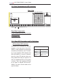
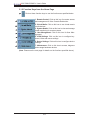
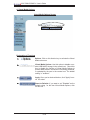
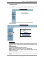
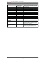
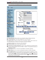
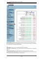
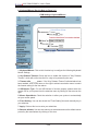
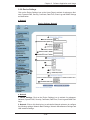
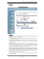
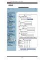
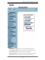
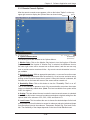
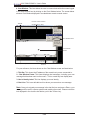
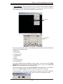
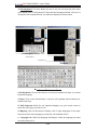
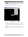
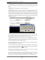
Chapter 3: Software Application and Usage 14. Miscellaneous Remote Console Settings: This window allows you to specify the following Remote Console Settings. 15. Start in Monitor Mode: Check this box to enable the Start in Monitor Mode which will allow data to be displayed in the remote monitor as soon as Remote Console is activated. (The data displayed in the remote monitor is ready-only.) 16. Start in Exclusive Access Mode: Check this box to enable the exclusive access mode immediately at Remote Console startup, which will force all other users connected to the network to close. No other users can open the Remote Console until you disable this function or log off. 0RXVH+RWNH\This option allows you to use a hotkey combination to specify the mouse synchronization mode or the single mouse mode. +RWNH\Enter a hotkey combination in the box to specify the mouse synchronization mode or the single mouse mode. 19. Remote Console Button Keys: 7KLVZLQGRZDOORZVWKHXVHUWRGH¿QHEXWWRQ keys for the remote host. The button keys allow simulating keystrokes on a remote host or issuing commands to a remote system. The button keys are needed when you have a missing key or when you want to prevent interference caused to the local system. After a remote console button key is set, it will appear on the right upper corner of the remote monitor screen as shown in the graphics below. (For details LQVWUXFWLRQVLQFUHDWLQJEXWWRQNH\VSOHDVHFOLFNRQWKHOLQN&OLFNKHUHIRU+HOS 20 Button Keys: Enter the syntax of a button key in the box. (For detailed instrucWLRQVLQFUHDWLQJEXWWRQNH\VSOHDVHFOLFNRQWKHOLQN&OLFNKHUHIRU+HOS 21 Name: Key in the name of a button key in the box. (For details instructions in FUHDWLQJEXWWRQNH\VSOHDVHFOLFNRQWKHOLQN&OLFNKHUHIRU+HOS 22 More Entries: Click on this icon to create more Button Keys. 19 3-23 AOC-SIMLC/SIMLC+ User's Guide b. Keyboard/Mouse (See the Note on Page 3-1.) KVM Settings: Keyboard/Mouse 2 3 4 5 6 7 8 1 1. Keyboard/Mouse: &OLFNRQWKLVIXQFWLRQNH\WRFRQ¿JXUHWKHIROORZLQJ.H\ERDUG Mouse Settings. 2. Key Release Timeout: &KHFN WKLV ER[ WR HQDEOH WKH IXQFWLRQ RI .H\ 5HOHDVH 7LPHRXWZKLFKZLOOVHWWKHWLPHOLPLWIRUDNH\WREHSUHVVHGE\WKHXVHU 3. Timeout after_______msec: ,IWKH.H\5HOHDVH7LPHRXWLQGLFDWHGDERYHKDV been enabled, click on the arrow on the right to activate a selection menu to select the timeout setting for the item above. 4. USB Mouse Type: For the USB Mouse to function properly, please select the correct OS for your system from the selection menu by clicking on the arrow on the right. 5. Mouse Speed-Auto: Check the selection to allow your system to automatically set your mouse speed. 6. Fixed Scaling: <RXFDQDOVRFKHFNWKH)L[HG6FDOLQJER[DQGPDQXDOO\NH\LQ your selection. 7. Apply: Click on this icon to enter your selections. 8. Reset to defaults: You can also cancel your selections and use the default values pre-set by the manufacturer by clicking on this icon. 3-24 Chapter 3: Software Application and Usage 3.2.6. Device Settings Click on the Device Settings icon on the Home Page to activate its submenus: NetZRUN'\QDPLF'166HFXULW\&HUWL¿FDWH'DWH7LPH(YHQW/RJDQG61036HWWLQJV as listed below. a. Network Device Settings: Network 3 4 5 6 7 8 9 10 111 12 13 14 15 16 1 17 2 18 19 20 a. Network 1. Device Settings: Click on the Device Settings icon to activate its submenus: 1HWZRUN'\QDPLF'166HFXULW\&HUWL¿FDWH'DWH7LPH(YHQW/RJDQG61036HWtings. 2. Network: &OLFNRQWKLVIXQFWLRQNH\WRDFWLYDWHWKH1HWZRUNVXEPHQXWRFRQ¿JXUH the following settings: Network Basic Settings, Network Miscellaneous Settings and LAN Interface Settings. 3-25 AOC-SIMLC/SIMLC+ User's Guide 3. Network Basic Settings: 7KLVZLQGRZDOORZV\RXWRFRQ¿JXUHEDVLFVHWWLQJVIRU your network. ,3$XWR&RQ¿JXUDWLRQClick on the box to activate the selection menu and select a desired item from the list. The options are None, DHCP, and BOODP. 3UHIHUUHG+RVW1DPH'+&3RQO\Enter a Preferred Host Name in the box. 6. IP Address: Enter the IP Address for the remote host in the box. 7. Subnet Mask: Enter the net mask of the local network in the box. 8. Gateway IP Address: Enter the local network router's IP address in this box for the accessibility of the users that are not connected to the local network. 9. Primary DNS Server IP Address: Enter the IP Address of the Primary Domain Name Server in the box. 10. Secondary DNS Server IP Address: Enter the IP Address of the Secondary Domain Name Server in the box. It will be used when the Primary DNS Server cannot be contacted. 11. Network Miscellaneous Setting: 7KLV¿HOGDOORZVWKHXVHUWRFRQ¿JXUHWKHIROlowing Network Miscellaneous settings as listed below: 5HPRWH&RQVROH+77363RUWEnter the port numbers the remote host and the HTTP server are listening. If a number is not entered in the box, the default value will be used. +7733RUWEnter the port number the HTTP server is listening. If a number is not entered in the box, the default value will be used. 66+3RUWEnter the port number the SSH server is listening. If a number is not entered in the box, the default value will be used. 15. Bandwidth Limit: Enter the maximum bandwidth value for network interfacing. The value should be in Kbits per second. (QDEOH66+$FFHVVClick this box to enable SSH Access. 17. Disable Setup Protocol: Check this box to disable the function of Setup Protocol for the SIMLC/SIMLC+ card. 18. LAN Interface Setting: 7KLV¿HOGDOORZVWKHXVHUWRFRQ¿JXUHWKHIROORZLQJ/$1 Interface settings as listed below: 19. LAN Interface Speed: Click on the arrow on the right to activate the selection menu and select a desired speed. The options are: Auto-detect, 10 Mega bits per second or 100 Mega bits per second. If Auto-detect is selected, LAN Interface 6SHHGZLOOEHVHWDWWKHRSWLPL]HGVSHHGEDVHGRQWKHV\VWHPFRQ¿JXUDWLRQVGHtected by the OS. 19. LAN Interface Duplex Mode: Click on the arrow on the right to activate the selection menu to select a desired LAN Interface Duplex Mode. The options are: Autodetect, Half Duplex and Full Duplex. If Auto-detect is selected, the LAN Interface 'XSOH[0RGHZLOOEHVHWWRWKHRSWLPL]HGVHWWLQJEDVHGRQWKHV\VWHPFRQ¿JXUDWLRQV detected by the OS. 3-26 Chapter 3: Software Application and Usage b. Dynamic DNS Device Settings: Dynamic DNS 2 3 4 5 6 7 8 9 10 1 b. Dynamic DNS 1. Dynamic DNS:&OLFNRQWKLVIXQFWLRQNH\WRDFWLYDWHLWVVXEPHQXDQGFRQ¿JXUH the following Dynamic DNS (-Domain Name Server) settings as listed below. 2. Enable Dynamic DNS: Check this box to enable the Dynamic DNS service. 3. Dynamic DNS Server www.dyndns.org: Click this link to access the DynDNS web site. This is the server name where the DDNS Service is registered. 4. DNS System: Dynamic DNS (Item#2 above) is enabled, you can select from the RSWLRQV&XVWRPRU'\QDPLFIURPWKHVHOHFWLRQPHQX6HOHFW&XVWRPWRXVH\RXU RZQV\VWHPDVWKH'16VHUYHU6HOHFW'\QDPLFWRXVHWKHSUHFRQ¿JXUHG'\QDPLF DNS as your server. +RVWQDPHEnter the name you want to use for the remote host server. 6/7. Username/Password: Enter the username and the password for the remote host user. &KHFNWLPH++00(QWHUWKHWLPHWKH6,0/&6,0/&FDUG¿UVWUHJLVWHUVZLWK the DNS server in the HH:MM Format. (e.g. 07:25, 19:30) 3-27 AOC-SIMLC/SIMLC+ User's Guide 9. Check Interval: Enter the interval for the IPMI to report to the Dynamic DNS again. 10. Delete Saved External IP Address: Click on the Delete Icon to delete the IP Address for an external system that has been previous entered and saved. 3-28 Chapter 3: Software Application and Usage c. Security Device Settings: Security 2 3 4 5 6 7 8 9 111 10 12 13 14 15 16 17 1 c. Security 1. Security:&OLFNRQWKLVIXQFWLRQNH\WRDFWLYDWHLWVVXEPHQXDQGFRQ¿JXUHWKHIROlowing Security settings as listed below. 2. Encryption Settings: 7KLVZLQGRZDOORZV\RXWRFRQ¿JXUHHQFU\SWLRQVHWWLQJV )RUFH +7736 IRU :HE $FFHVV Check this box to enable the function-Force HTTPS for Web Access. If enabled, you will need to use an HTTPS connection to access to the web. 4. KVM Encryption: 7KLVRSWLRQDOORZV\RXWRFRQ¿JXUHWKHHQFU\SWLRQRIWKH5)% protocol. RFB is used by the remote host to transmit video data displayed in the host monitor to the local administrator machine, and transmit keyboard and mouse data from the local administrator machine back to the remote host. ,IVHWWR2IIQRHQFU\SWLRQZLOOEHXVHG,IVHWWR7U\WKHDSSOHW-90RIWKHUHPRWH host) will attempt to make an encrypted connection. In this case, when a connection FDQQRWEHHVWDEOLVKHGDQXQHQFU\SWHGFRQQHFWLRQZLOOEHXVHG,IVHWWR)RUFHWKH applet will make an encrypted connection. In this case, an error will be reported if no connection is made. (See the note on Page 3-1.) 5. IP Access Control: 7KLVVHFWLRQDOORZV\RXWRFRQ¿JXUHWKH,3$FFHVV&RQWURO settings listed below. 3-29 AOC-SIMLC/SIMLC+ User's Guide 6. Enable IP Access Control: Check this box to enable the function of IP Access Control. This function is used to limit user access to the network by identifying them by their IP addresses. (This function is available to the LAN interface only.) 7. Default Policy: :KHQLWHP,3$FFHVV&RQWUROVHWWRHQDEOHG\RXFDQVHOHFW HLWKHU DFFHSW RU GURS DOORZLQJ DFFHVV RU GHQ\LQJ DFFHVV DFFRUGLQJ WR SUHGH¿QHGUXOHVNote,IWKLVRSWLRQLVVHWWRGURSDQG\RXGRQRWKDYHDVHWRIUXOHV that will accept the internet connection, then the internet connection over LAN is impossible. In this case, you need to change your security settings via modem or by disabling the IP Access Control.) 8. Rule#: Enter a rule number in the box for a command (or commands) that will be used by the IP Access Control. 9. IP/Mask: Enter the IP Address or an IP Address Range for which the command(s) will be applied. 10. Policy: This item instructs the IPMI what to do with the matching packages. (Note: The sequence or the order of the rules is important. The rules are checked in the ascending order until a rule matches. All rules below the matching one will be ignored. The default policy applies if no matching rules are found.) 11. Append: Select this option to add IP Address/Mask, rules or commands to the existing ones. 12. Insert: Select this option to insert IP Address/Mask, rules or commands to the existing ones. 13. Replace: Select this option to replace an old IP Address/Mask, rule or command with a new one. 14. Delete: Select this option to delete (a part of) an existing IP Address/Mask, rule or command. 15. User Blocking: This window allows you to set the conditions how a user is blocked. 16. Max. Number of Failed Logins: Enter the maximum number of failed attempts or failed logins allowed for a user. If the number of failed logins or attempts exceeds this maximum number allowed, the user will be blocked from system. Note:,IWKLVER[LVOHIWHPSW\WKHXVHULVDOORZHGWRWU\WRORJLQWRWKHVHUYHULQ¿QLWHO\ For network security, this is not recommended. 17. Block Time (Minutes): Enter the number of minutes allowed for a user to attempt to login. If the user fails to login within this time allowed, the user will be blocked from system. Note:,IWKLVER[LVOHIWHPSW\WKHXVHULVDOORZHGWRWU\WRORJLQWRWKHVHUYHULQ¿QLWHO\ For network security, this is not recommended. 3-30 Chapter 3: Software Application and Usage G&HUWL¿FDWH 'HYLFH6HWWLQJV&HUWL¿FDWH 2 3 4 5 6 7 8 9 10 111 12 13 1 G&HUWL¿FDWH &HUWL¿FDWH&OLFNRQWKLVIXQFWLRQNH\WRDFWLYDWHLWVVXEPHQXDQGFRQ¿JXUHWKH IROORZLQJ&HUWL¿FDWHVHWWLQJVDVOLVWHGEHORZ &HUWL¿FDWH6LJQLQJ5HTXHVW&657KLVZLQGRZDOORZV\RXWRGH¿QHWKH&HUWL¿FDWH6LJQLQJ5HTXHVW&65IRUP7KH,30,XVHVWKH6HFXUH6RFNHW/D\HU66/ SURWRFRO IRU HQFU\SWHG QHWZRUN WUDI¿F EHWZHHQ LWVHOI DQG WKH UHPRWH KRVW VHUYHUV When a connection is made, the IPMI has to expose its identity to a remote host by XVLQJDFU\SWRJUDSKLFFHUWL¿FDWH Note: SHA1 and RSA 2048 bit SSL supported. 7RFUHDWHDFHUWL¿FDWHWKDWLVXQLTXHWRDSDUWLFXODU,30,FDUGRU6,0/&6,0/&FDUG DFHUWL¿FDWLRQDXWKRULW\&$QHHGVWR¿OORXWWKH&65IRUPLQGLFDWHGLQWKH&65ZLQGRZDERYHDQGFOLFN&UHDWHWRJHQHUDWHLW 3-31 AOC-SIMLC/SIMLC+ User's Guide 3. Common Name: (QWHUWKHIXOO\TXDOL¿HGGRPDLQQHWZRUNQDPHRIWKH,30, 4. Organization Unit: Enter the name of the department within an organization that the IPMI belongs to. 5. Organization: Enter the name of the organization that the IPMI belongs to. 6. Locality/City: Enter the name of the city or the location where the organization is located. 7. State/Province: Enter the name of the state/province where the organization is located. 8. Country (ISO): Enter the name of the country or the ISO code where the organization is located. 9. Email: Enter the email address of a contact person that is responsible for the IPMI. 10. Challenge Password: (QWHUDFKDOOHQJH3DVVZRUGIRUWKH&HUWL¿FDWLRQ$XWKRULW\ WRDXWKRUL]HQHFHVVDU\FKDQJHVWRWKHFHUWL¿FDWHDWDODWHUWLPH7KHSDVVZRUGVKDOO be four characters or longer. &RQ¿UP&KDOOHQJH3DVVZRUGEnter a challenge Password one more time to FRQ¿UPLW 12. Key Length (bits): This is the length of key generated in bits. 3-32 Chapter 3: Software Application and Usage e. Date/Time Device Settings: Date/Time 2 3 4 5 6 1 e. Date/Time 1. Date/Time: Click on this function key to activate its submenu. This feature allows you to set the internal realtime clock for your SIMLC/SIMLC+ card. 2. UTC Offset: This window allows you to offset the UTC Timer. 8VHU6SHFL¿HG7LPHThis option allows the user to enter the time values for the SIMLC/SIMLC+ internal realtime clock. 4. Synchronize with NTP Server: Enter the IP Address for the NTP (Network Time Protocol) Server that you want your SIMLC/SIMLC+ internal realtime clock to synchronize with. 5/6. Primary Time Server/Secondary Time Server: Enter the IP Address for the primary NTP Server and the secondary NTP Server that you want your SIMLC/SIMLC+ internal realtime clock to synchronize with. (The daylight saving time cannot be automatically adjusted. Please manually set up the UTC offset twice a year for your timer to work properly.) 3-33 AOC-SIMLC/SIMLC+ User's Guide f. Event Log Device Settings: Event Log 2 3 4 5 6 7 8 9 10 111 12 13 14 15 16 17 18 1 19 20 21 22 23 3-34 Chapter 3: Software Application and Usage f. Event Log 1. Event Log: Click on this function key to activate its submenu. This feature allows you to set Event Log Targets and Event Log Assignment. 2. Event Log Targets: This section allows you to manually set the event log targets and settings. 3. List Logging Enabled: Check this box to activate the event-logging list. To show WKHHYHQWORJOLVWFOLFNRQ(YHQW/RJRQWKH0DLQWHQDQFHSDJH7KHPD[LPXP number of log list entries is 1,000 events. Every entry that exceeds this limit will automatically override the oldest one in the list. If the reset button is pressed, all logJLQJLQIRUPDWLRQZLOOEHVDYHGKRZHYHUDOOORJJLQJGDWDZLOOEHORVWLIKDUGUHVHWLV performed or the system loses power.) 4. Entries Shown Per Page: Enter the number of entries you want to display on a page. 5. Clear Internal Log: Click this icon to clear internal event log from the memory. 6. NFS Logging Enable: Click this box to enable NFS Logging which will create a Network File System (NFS) for the event logging data to be written into. 7. NFS Server: Enter the IP Address of the NFS Server. 8. NFS Share: Enter the path of the Network File System in which the event logging data is stored. 9. NFS Log File: (QWHUWKH¿OHQDPHRIWKH1HWZRUN)LOH6\VWHPLQZKLFKWKHHYHQW logging data is stored. 10. SMTP Logging Enable: Check this box to enable the function of SMTP (Simple Mail Transfer Protocol) logging. 11. SMTP Server: Enter the IP Address for the SMTP Server. 12. Receiver Email Address: Enter the email address that the SMTP event logging data will be sent to. 13. Sender Email Address: Enter the email address from which the SMTP event logging data is sent. 14. SNMP Logging Enable: Check this box to enable the function of SNMP (Simple Network Management Protocol) logging. 15. Destination IP: Enter the IP address where the SNMP trap will be sent to. 16. Community: Enter the name of the community if the receiver requires a community string. 17. Click here to view the Supermicro Daughter Card SNMP MIB: Click this link to see the SMLP card SNMP MIB. 18. Event Log Assignments: This window allows you to specify the types and the destination for the event logging. 3-35 AOC-SIMLC/SIMLC+ User's Guide g. SNMP Settings Device Settings: SNMP Settings 2 3 4 5 6 7 1 g. SNMP Settings 1. SNMP Settings: Click on this function key to activate its submenu. This feature DOORZV\RXWRFRQ¿JXUH6LPSOH1HWZRUN0DQDJHPHQW3URWRFROVHWWLQJV 2. Enable SNMP Agent: Check the box to enable the SNMP Agent and allow it to interface with your SIMLC/SIMLC+ card. 3. Read Community: Enter the name of the SNMP Community from which you will retrieve information via SNMP. 4. Write Community: Enter the name of the SNMP Community to which you can write information and issue commands via SNMP. 3-36 Chapter 3: Software Application and Usage 5. System Location: Enter the physical location of the SNMP host server. This locaWLRQZLOOEHXVHGLQUHVSRQVHWRWKH6103UHTXHVWDVV\V/RFDWLRQ 6. System Contact: Enter the name of the contact person for the SNMP host server. 7KLVYDOXHZLOOEHUHIHUUHGWRDVV\V&RQWDFW 7. Click here to view the SNMP MIB: Click this link to view the SMLP card SNMP 0,%¿OH7KLV¿OHPD\EHQHFHVVDU\IRUDQ6103FOLHQWWRLQWHUIDFHZLWKWKH6,0/& SIMLC+ card. 3-37 AOC-SIMLC/SIMLC+ User's Guide 3.2.7 Maintenance Click on the Maintenance icon on the Home Page to activate its submenus: Device Information, Event Log, Update Firmware and Unit Reset Settings as listed below. a. Device Information Maintenance: Device Information 2 3 1 1. Device Information: Click on this function key to activate its submenu. This feaWXUHGLVSOD\VWKHLQIRUPDWLRQRIWKH6,0/&6,0/&FDUGDQGLWV¿UPZDUH 2. View the Data File for Support: &OLFNRQWKLVOLQNWRYLHZWKH;0/¿OHZKLFKFRQtains you and your product information which is needed for technical support. 2. Connect Users: List the name(s), the IP Address(es) and the status of the connect person(s). 3-38 Chapter 3: Software Application and Usage b. Event Log Maintenance: Event Log 1 1. Event Log: Click on the function key on the left to activate the Event Log submenu. Once the submenu is displayed, the Event Log List will display. The Event Log List contains the information of events that are recorded by the SIMLC/SIMLC+ in the order of Date/Time, Types, and the descriptions of the events including the IP address(es), person(s) and activities involved . 3-39 AOC-SIMLC/SIMLC+ User's Guide c. Update Firmware Maintenance: Update Firmware 3 2 4 1 1. Update Firmware:&OLFNRQWKLVIXQFWLRQNH\WRHQDEOH8SGDWH)LUPZDUH 2/3. Firmware File:(QWHUWKHQDPHRIWKH¿UPZDUH\RXZDQWWRXSGDWHRUFOLFNRQ WKH%URZVHULFRQWRVHOHFWWKH¿UPZDUH¿OH 4. Update:&OLFNRQWKH8SORDGLFRQWRXSORDGWKH¿UPZDUH¿OHWRWKHVHUYHUIRUWKH update. (Note7KLVSURFHVVLVQRWUHYHUVLEOHRQFHWKH¿UPZDUHLVXSGDWHGVRSURceed with caution. It might take a few minutes to complete the procedure.) 3-40 Chapter 3: Software Application and Usage d. Unit Reset Maintenance: Unit Reset 2 3 4 5 1 1. Unit Reset: This feature allows you to reset the following components: 2. Reset Keyboard/Mouse:&OLFNWKH5HVHWLFRQWRUHVHW.H\ERDUGPRXVH 3. Reset USB:&OLFNWKH5HVHWLFRQWRUHVHWWKH86%PRGXOH 4. Reset Video Engine:&OLFNWKH5HVHWLFRQWRUHVHW9LGHRDQGLWVFRQWUROOHU 5. Reset Device:&OLFNWKH5HVHWLFRQWRFROGUHVHWWKH,30,¿UPZDUH 3-41 AOC-SIMLC/SIMLC+ User's Guide 3.3 Remote Console Main Page Home 1 Log Out Click to Open Console 2 4 3 9 Remote Console Preview Screen Refresh 5 6 Power On 7 Power Down 8 Reset After you have entered the correct IP address for your remote console and typed in correct user name and password, you should be connected to the remote console. When the remote console is connected, the Remote Console window displays as shown above. To go to the remote console screen, you can do one of the following: &OLFNRQWKHFRQVROHLFRQPDUNHGRQWKHXSSHUOHIWFRUQHURU &OLFNRQWKHOLQN&OLFNWR2SHQWRRSHQWKHUHPRWHFRQVROHVFUHHQDVVKRZQRQ #3 above. The remote console screen as shown on the next page displays. Note: For your reference, the functions of the icons for this home page are listed below: +RPH: Click this icon to return to the Home Page. 2. Console: Click this icon to open the remote console screen. 3. Click to Open: Click this link to open the remote console screen. 4. Log-Out: Click this icon to log out. 5. Refresh: Click this icon to refresh the remote console preview screen. 6. Power On: Click this icon to power on the remote server. 7. Power down: Click this icon to power down the remote server. 8. Reset: Click this icon to reset the remote server. 9. Remote Console Preview Screen: This window displays the preview of the remote console screen. Click on this window to go to the remote console screen. 3-42 Chapter 3: Software Application and Usage 3.3.1 Remote Console Options $IWHUWKHUHPRWHFRQVROHVFUHHQDSSHDUVFOLFNRQWKHEXWWRQ2SWLRQRQWKHYHU\ upper right corner to display the Options Menu as shown below.Options Menu Options a. Options Menu Items No KB/Mouse: The following items are included in the Options Menus: (Crossed-out) 1. Monitor Only:&OLFNRQWKH0RQLWRU2QO\EXWWRQWRWXUQWKHIXQFWLRQRI0RQLWRU 2QO\RQRURII,IWKHIXQFWLRQRI0RQLWRU2QO\LVVHOHFWHGWKH.%0RXVHLFRQRQ the lower right corner will be crossed out as shown above, and the user can only view or monitor remote console activities. Any remote console interaction is no longer available. 2. Exclusive Access: With an appropriate permission, a user can force other users to quit the remote console and claim the console for his or her own exclusive use by clicking on the Exclusive Access icon to select it. When this function is selected, the 2nd user icon on the lower left corner of the screen will be crossed out. 3. Readability Filter:&OLFNRQWKLVEXWWRQWRWXUQWKH5HDGDELOLW\)LOWHURQRURII Turn on this function to preserve most of the screen details even when the screen image is substantially scaled down. (Note: This item is available for a system with a JVM 1.4 or higher.) 4. Scaling: This item allows the user to scale the remote console screen to a desired size. Click on this button to access its submenu and select a desired setting from the options listed in the submenu: 25%, 50%, 100% and Scale to Fit. 5. Local Cursor: This item allows the user to choose the desired shape for the local cursor pointer. Click on this button to access its submenu and select a desired shape from the options listed in the submenu: Transparent, Default, Big, Pixel, and Crosshair. The availability of the shapes depends on the Java Virtual Machine used. 3-43 AOC-SIMLC/SIMLC+ User's Guide 6. Chat Window: This item allows the user to communicate with other users logged in the same remote host by clicking on the Chat Window button. The screen below shows a Chat Window displayed in a scaled down remote console screen. Remote Console Window Title Bar (Scaled-down to 50%) Chat Window button 1 Chat Window 2 Frame 3 4 User's Identity Label Chat line For your reference, the items shown on the Chat Window screen are listed below: 1. Title Bar: This shows the IP address of the remote host you are connected to. 2. Chat Window Frame: This frame displays chat messages, including your own message that has been sent to other users. This is a read-only test display area. 3. User's Identity Label: This line displays your own identity. 4. Chat Line: This is an edit-able text line where you can enter a new message. Note: Once you've typed your message in the chat line box and press <Enter>, your message will be sent to remote systems and read by other users. Please review the text displayed in the chat line box before you hit the <Enter> key. 3-44 Chapter 3: Software Application and Usage 7. Video Settings: This item allows the user to set the monitor display settings by FOLFNLQJRQWKH9LGHR6HWWLQJVEXWWRQPDUNHGEHORZ$IWHU\RX YHFOLFNHGWKH Video Settings button, the submenu displays as shown below. Video Settings 1 Button 2 3 Video Settings Submenu 4 5 7 6 Use your cursor pointer to click on the triangles (marked 2 and 3) to adjust the setting for each of the following items: i. Brightness ii. Contrast Red iii. Contrast Green iv. Contrast Blue v. Clock vi. Phase vii. Horizontal Offset viii. Vertical Offset ,I\RXDUHQRWKDSS\ZLWKWKHFKDQJHV\RXKDYHPDGH\RXFDQFOLFNRQWKHReset this ModeEXWWRQPDUNHGWRUHVHWDSDUWLFXODULWHPRUFOLFNRQWKHReset All ModesEXWWRQPDUNHGDERYHWRUHVHWDOOLWHPV 7RVDYHDOOFKDQJHVFOLFNRQWKHSave ChangesEXWWRQ0DUNHG<RXFDQDOVR FOLFNRQWKHUndo Changes0DUNHGDERYHWRDEDQGRQWKHFKDQJHV ,I6DYH&KDQJHVLVVHOHFWHGWKHFRQ¿UPDWLRQPHVVDJHDVVKRZQEHORZDSSHDUV &OLFN2.WRVDYHWKHFKDQJHV&OLFN&DQFHOWRUHWXUQWRWKHSUHYLRXVPHQX 3-45 AOC-SIMLC/SIMLC+ User's Guide 8. Soft Keyboard: This item allows the user to use the soft keys that have been SUHLQVWDOOHGLQWKH6RIW.H\ERDUGRIWKHSDUWLFXODUODQJXDJHVHOHFWHG$IWHU\RX YH clicked the Soft Keyboard button, the submenu displays as shown below. 1 2 4 3 5 Keys in the Soft Keyboard Language List 3 Keys in English Soft Keyboard i Soft Keyboard: Click on this button to use the pre-installed soft keys or to select keyboard language. ii. Show:&OLFNRQWKH6KRZ%XWWRQWRVKRZDVRIWNH\ERDUGZKLFKFRQWDLQVSUH installed soft keys. iii. Soft Keyboard: When the soft keyboard displays, use your mouse cursor to select the soft key(s) you want to use. iv. Mapping: Click on this button to display a list of major languages of the world. Select from the list the language you want the soft keyboard to be in. v. Language List: When this language list displays, select the language you want to use by clicking on it. 3-46 Chapter 3: Software Application and Usage 9. Local Keyboard: This item allows the user to manually change the local keyboard setting for interaction with a remote host. Use this function to change the language mapping of your browser machine running the remote console host. After you have clicked Local Keyboard button, the submenu displays as shown below. 1 2 Local Keyboard Button Language List i Local Keyboard: Click on this button to manually change the local keyboard setting for remote console interaction. Use this function to change the language mapping of your browser machine running the remote console host. Click on this button to display a list of major languages in the world. ii. Language List: When this language list displays, select the language you want to use. 3-47 AOC-SIMLC/SIMLC+ User's Guide 10. +RW.H\V: 7KLVLWHPDOORZVWKHXVHUWRVHOHFWDSUHGH¿QHGKRWNH\IURPDKRW key list. Once a hot key is selected, the command associated with the hot key will be sent to the remote console host for execution. After you've clicked Hot Key button, the submenu displays as shown below. 1 2 Hot Key Button Hot Key List L+RW.H\%XWWRQ Click on this button to display a hot key list. This list contains WKHKRWNH\VWKDWKDYHEHHQSUHGH¿QHG DQGSUHHQWHUHG LQWKHV\VWHP<RXFDQ also use this function to write your own commands and add your own hot keys to the list. LL+RW.H\/LVW Select from the list a hot key you wish to use. By selecting a hot key, you will send the command associated with this hot key will be sent to the remote host for execution. 3-48 Chapter 3: Software Application and Usage 11. Remote Console Interface Window: This item allows the local host to interact with a remote server. Through the Remote Console Interface Window, the user can VKDUH¿OHVVWRUHGLQWKHORFDOGULYHZLWKDXVHUFRQQHFWHGWRWKHUHPRWHVHUYHUGRZQload data from a local drive to the remote server, issue commands to manage the remote server, or allow the remote server be controlled and managed by a local user logged in the remote server. This function provides a full spectrum of remote console interaction and management. You also need to have the Administrator Privilege to use this feature. To access the Remote Console Interface window, you need to click the Console icon on the Remote Console window as shown below. Console Icon Remote Console Window Once you have clicked on the Console Icon on the Remote Console window, the Remote Console Interface window displays as shown below. 1 3 4 5 6 2 7 Remote Console Interface Window 3-49 AOC-SIMLC/SIMLC+ User's Guide i./ii. Local Drive List: The box displays a list of local drives available for remote access. Select from the list a local drive that you want to make accessible for a remote server. iii. Refresh: Click this button to refresh the local drive list. iv. Write Support: Check this button to allow the remote operating system to have write access to the drive that you have selected. This function allows a user to alter, overwrite, erase and destroy data stored in the drive selected. This feature should RQO\EHXVHGZLWKQRQFULWLFDOGDWD:KHQ:ULWH6XSSRUWLVFKHFNHGWKHZDUQLQJ message as shown below will display. Read the warning message carefully before enabling this function. Warning Message v. Connect: Click this button to make the drive you have selected accessible for rePRWHFRQVROHLQWHUDFWLRQ2QFH\RXKDYHFOLFNHGFRQQHFWXVHUVORJJHGLQUHPRWH servers will have access to the local drive that you have selected. vi. Disconnect: Click this button to cancel the connection established between a local drive and a remote server. Once you click this button, the drive you have selected will not be accessible for remote console interface. vii. Sending Commands7KLVIXQFWLRQVDOORZVWKHXVHUWRLVVXHDSUHGH¿QHGFRPmand to a remote server for execution. To use this function, you need to click the hot keys displayed on the upper right corner of the screen as shown below. (Note: Hot keys are the commands that have EHHQSUHGH¿QHGDQGSUHVWRUHGLQDUHPRWHFRQVROHV &OLFN %XWWRQ &WUO$OW'HOHWH DV VKRZQ RQ 3DJH WR VHQG WKH FRPPDQG &WUO$OW'HOHWHWRWKHUHPRWHVHUYHUIRUH[HFXWLRQ Once you have clicked on the button, a message displays, asking you if you really ZDQWWRVHQG&WUO$OW'HOHWHDVVKRZQLQWKHSLFWXUHRQWKHQH[WSDJH&OLFN<HV WRFRQ¿UPLWRUFOLFN&DQFHOWRVWRSVHQGLQJWKHFRPPDQGIRUUHPRWHH[HFXWLRQ 3-50 Chapter 3: Software Application and Usage &RQ¿UPLQJ0HVVDJH 3-51 AOC-SIMLC/SIMLC+ User's Guide To Log Out 5HWXUQWRWKH+RPH3DJHDQGFOLFNRQWKH/RJ2XWEXWWRQWRORJRXWIURP5HPRWH Console Interface. Logout 3-52 Chapter 4: Troubleshooting Chapter 4 Frequently Asked Questions 4XHVWLRQV+RZGR,ÀDVKWKH¿UPZDUHRIDQ,30,FDUGVXFKDVD6,0/& SIMLC+ card? Answer: /RJRQWRWKHZHELQWHUIDFHSDJHRIWKH,30,FDUGE\W\SLQJWKH,3DGGUHVV of the card. &OLFNRQWKHPDLQWHQDQFHEXWWRQ %URZVHWRFKRRVHWKHFRUUHFW¿OHWRÀDVKWKH¿UPZDUH &OLFNRQWKH8SGDWH)LUPZDUHEXWWRQDQGSURFHHGZLWK¿UPZDUHÀDVKLQJ 4XHVWLRQV+RZGR,VHWXSWKH,3DGGUHVVDQG0$&DGGUHVVIRUWKH$2& SIMLC/SIMLC+ Add-On card? Answer: %RRWWKHV\VWHPLQWR'26 5XQWKHXWLOLW\,310$&IURP'26 )ROORZWKHSURPSWVWRVHWXSWKH,3$GGUHVVDQG0$&DGGUHVVIRUWKH$2& SIMLC/SIMLC+. Contacting Supermicro's Technical Support: If you still have problems after trying out all the recommended solutions, please contact our Tech. Support @ (408)503-8000 or visit our web site @ www. supermicro.com/support/. 4-1 AOC-SIMLC/SIMLC+ User's Guide Notes 4-2