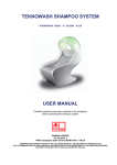
1
Sun StorageTek™
1U Rackmount Media Tray
nl
Reference Guide
Sun Doc Part Number: 875‐4297‐10
Second edition: December 2007
Legal and notice information
© Copyright 2007 Hewlett‐Packard Development Company, L.P.
This document was created by Hewlett‐Packard Company (“HP”) for Sun Microsystems, Inc. (“Sun”).
Sun makes no warranties of any kind with regard to this material, including, but not limited to, the implied warranties of
merchantability and fitness for a particular purpose. Sun shall not be liable for errors contained herein or for incidental or
consequential damages in connection with the furnishing, performance, or use of this material.
This document contains proprietary information, which is protected by copyright. No part of this document may be
photocopied, reproduced, or translated to another language without the prior written consent of Sun.
Sun shall not be liable for technical or editorial errors or omissions contained herein. The information is provided ʺas isʺ without
warranty of any kind and is subject to change without notice. The warranties for Sun products are set forth in the express
limited warranty statements for such products. Nothing herein should be construed as constituting an additional warranty.
Other trademarks may be mentioned herein which belong to other companies.
Patented under one or more of U.S. Patents Nos. 5,003,307; 5,016,009; 5,463,390; 5,506,580; held by Hi/fn, Inc.
Microsoft, Windows, Windows NT, and Windows XP are U.S. registered trademarks of Microsoft Corporation.
UNIX® is a registered trademark of The Open Group.
Contents
About this guide . . . . . . . . . . . . . . . . . . . . . . . . . .
Intended audience . . . . . . . .
Document conventions and symbols
Rack stability . . . . . . . . . .
Sun technical support . . . . . .
Sun websites . . . . . . . . . .
Documentation feedback . . . . .
.
.
.
.
.
.
.
.
.
.
.
.
.
.
.
.
.
.
.
.
.
.
.
.
.
.
.
.
.
.
.
.
.
.
.
.
.
.
.
.
.
.
.
.
.
.
.
.
.
.
.
.
.
.
.
.
.
.
.
.
.
.
.
.
.
.
.
.
.
.
.
.
.
.
.
.
.
.
.
.
.
.
.
.
.
.
.
.
.
.
.
.
.
.
.
.
.
.
.
.
.
.
.
.
.
.
.
.
.
.
.
.
.
.
.
.
.
.
.
.
.
.
.
.
.
.
.
.
.
.
.
.
.
.
.
.
.
.
.
.
.
.
.
.
.
.
.
.
.
.
.
.
.
.
.
.
.
.
.
.
.
.
.
.
.
.
.
.
.
.
.
.
.
.
1 Introduction . . . . . . . . . . . . . . . . . . . . . . . . . . .
Standard features . . . . . . . . . . . . . . . . . .
Media tray components . . . . . . . . . . . . . . .
Media tray front panel components . . . . . . . .
Media tray rear panel components . . . . . . . . .
Media tray internal components (SAS version shown)
2 Device installation
.
.
.
.
.
.
.
.
.
.
.
.
.
.
.
.
.
.
.
.
.
.
.
.
.
.
.
.
.
.
.
.
.
.
.
.
.
.
.
.
.
.
.
.
.
.
.
.
.
.
.
.
.
.
.
.
.
.
.
.
.
.
.
.
.
.
.
.
.
.
.
.
.
.
.
.
.
.
.
.
.
.
.
.
.
.
.
.
.
.
. . . . . . . . . . . . . . . . . . . . . . . .
Cabling with two devices . . . . . .
SAS devices . . . . . . . . .
SCSI devices . . . . . . . . .
Two devices on one SCSI bus
One device per SCSI bus . .
3 Rack installation
.
.
.
.
.
.
.
.
.
.
.
.
.
.
.
.
.
.
.
.
.
.
.
.
.
.
.
.
.
.
.
.
.
.
.
.
.
.
.
.
.
.
.
.
.
.
.
.
.
.
.
.
.
.
.
.
.
.
.
.
.
.
.
.
.
.
.
.
.
.
.
.
.
.
.
.
.
.
.
.
.
.
.
.
.
.
.
.
.
.
.
.
.
.
.
.
.
.
.
.
.
.
.
.
.
.
.
.
.
.
.
.
.
.
.
.
.
.
.
.
.
.
.
.
.
.
.
.
.
.
.
.
.
.
.
.
.
.
.
.
.
.
.
.
.
. . . . . . . . . . . . . . . . . . . . . . . . .
Rail mounting kit . . . . . . . . . . . . . . . . .
Tools required . . . . . . . . . . . . . . . .
Installing the media tray in a rack . . . . . . . . . .
Before you begin . . . . . . . . . . . . . . .
Installing the component rails . . . . . . . . . .
Installing the rack rails . . . . . . . . . . . . .
Installation in racks with round or square holes
Installation in racks with 10‐32 threaded holes
Completing the installation . . . . . . . . . . .
.
.
.
.
.
.
.
.
.
.
.
.
.
.
.
.
.
.
.
.
.
.
.
.
.
.
.
.
.
.
.
.
.
.
.
.
.
.
.
.
.
.
.
.
.
.
.
.
.
.
.
.
.
.
.
.
.
.
.
.
.
.
.
.
.
.
.
.
.
.
.
.
.
.
.
.
.
.
.
.
.
.
.
.
.
.
.
.
.
.
.
.
.
.
.
.
.
.
.
.
.
.
.
.
.
.
.
.
.
.
.
.
.
.
.
.
.
.
.
.
.
.
.
.
.
.
.
.
.
.
.
.
.
.
.
.
.
.
.
.
.
.
.
.
.
.
.
.
.
.
.
.
.
.
.
.
.
.
.
.
.
.
.
.
.
.
.
.
.
.
.
.
.
.
.
.
.
.
.
.
.
.
.
.
.
.
.
.
.
.
.
.
.
.
.
.
.
.
.
.
.
.
.
.
.
7
7
7
8
8
8
8
9
9
10
10
10
11
13
16
16
16
16
18
19
19
19
20
20
20
21
21
22
24
A Electrostatic discharge . . . . . . . . . . . . . . . . . . . . . . .
27
B Specifications . . . . . . . . . . . . . . . . . . . . . . . . . . .
29
Index . . . . . . . . . . . . . . . . . . . . . . . . . . . . . . .
31
Preventing electrostatic discharge . . . . . . . . . . . . . . . . . . . . . . . . . . . . . . .
Grounding methods to prevent electrostatic discharge . . . . . . . . . . . . . . . . . . . . . .
Sun StorageTek™1U Rackmount Media Tray
27
27
3
Figures
1 The 1U Rackmount Media Tray
. . . . . . . . . . . . . . . . . . . . . . . . . .
9
. . . . . . . . . . . . . . . . . . . . . . . . . . . . .
10
3 Rear panel components . . . . . . . . . . . . . . . . . . . . . . . . . . . . . .
10
4 Internal components . . . . . . . . . . . . . . . . . . . . . . . . . . . . . . .
11
5 Removing the top access panel . . . . . . . . . . . . . . . . . . . . . . . . . . .
13
6 Removing the device blank . . . . . . . . . . . . . . . . . . . . . . . . . . . .
14
7 Removing the mounting brackets
. . . . . . . . . . . . . . . . . . . . . . . . .
14
8 Installing the mounting brackets . . . . . . . . . . . . . . . . . . . . . . . . . .
14
9 Installing the device
. . . . . . . . . . . . . . . . . . . . . . . . . . . . . . .
15
10 Attaching the cables
. . . . . . . . . . . . . . . . . . . . . . . . . . . . . . .
15
11 Replacing the access panel . . . . . . . . . . . . . . . . . . . . . . . . . . . . .
16
12 Two‐device SCSI configuration . . . . . . . . . . . . . . . . . . . . . . . . . . .
17
13 Single‐device SCSI configuration . . . . . . . . . . . . . . . . . . . . . . . . . .
18
14 Rail mounting kit components . . . . . . . . . . . . . . . . . . . . . . . . . . .
19
15 Installing the rails
. . . . . . . . . . . . . . . . . . . . . . . . . . . . . . . .
21
16 Inserting the pins in racks with round or square holes . . . . . . . . . . . . . . . . .
22
17 Locking the rails in racks with round or square holes . . . . . . . . . . . . . . . . .
22
18 Removing the pins in racks with 10–32 threaded holes
. . . . . . . . . . . . . . . .
23
19 Attaching the front mounting plate . . . . . . . . . . . . . . . . . . . . . . . . .
23
20 Locking the rails in racks with 10–32 threaded holes
. . . . . . . . . . . . . . . . .
24
21 Completing the installation . . . . . . . . . . . . . . . . . . . . . . . . . . . .
24
22 Plugging in the power cord . . . . . . . . . . . . . . . . . . . . . . . . . . . .
25
23 Installing the cable support clips . . . . . . . . . . . . . . . . . . . . . . . . . .
25
2 Front panel components
4
Tables
1 Document conventions . . . . . . . . . . . . . . . . . . . . . . . . . . . . . .
Sun StorageTek™1U Rackmount Media Tray
7
5
6
About this guide
This guide provides information about:
• Features and components of the 1U Rackmount Media Tray
• Racking the media tray
• Specifications
Intended audience
This guide is intended for system administrators with knowledge of:
• Storage systems
• Backup systems
Document conventions and symbols
Table 1 Document conventions
Convention
Element
Blue text: Table 1 on page 7
Cross‐reference links and e‐mail addresses
Blue, underlined text: http://www.sun.com
website addresses
Bold text
• Keys that are pressed
• Text typed into a GUI element, such as a box
• GUI elements that are clicked or selected, such as
menu and list items, buttons, tabs, and check boxes
Italic text
Text emphasis
Monospace text
•
•
•
•
Monospace, italic text
• Code variables
• Command variables
Monospace, bold text
Emphasized monospace text
File and directory names
System output
Code
Commands, their arguments, and argument values
WARNING!
Indicates that failure to follow directions could result in bodily harm or death.
CAUTION:
Indicates that failure to follow directions could result in damage to equipment or data.
IMPORTANT:
Provides clarifying information or specific instructions.
Sun StorageTek™1U Rackmount Media Tray
7
NOTE:
Provides additional information.
Rack stability
Rack stability protects personnel and equipment.
WARNING!
To reduce the risk of personal injury or damage to equipment:
• Extend leveling jacks to the floor.
• Ensure that the full weight of the rack rests on the leveling jacks.
• Install stabilizing feet on the rack.
• In multiple‐rack installations, fasten racks together securely.
• Extend only one rack component at a time. Racks can become unstable if more than one
component is extended.
Sun technical support
Telephone numbers for worldwide technical support are listed on the Sun support website:
http://www.sun.com/service/contacting/solution.html.
Collect the following information before calling:
•
•
•
•
•
•
SunSpectrum contract number
Product serial numbers
Product model names and numbers
Error messages
Operating system type and revision level
Detailed questions
For continuous quality improvement, calls may be recorded or monitored.
Sun websites
For additional information, see the following Sun websites:
•
•
•
•
http://www.sun.com — Sun corporate website
http://www.sun.com/storagetek/tape_storage — Sun storage products
http://www.sun.com/service/contacting/solution.html — Sun Support website
http://docs.sun.com/app/docs — documentation about Sun products
Documentation feedback
Sun Microsystems welcomes your feedback.
To make comments and suggestions about product documentation, please submit comments at:
http://www.sun.com/hwdocs/feedback. All submissions become the property of Sun Microsystems.
8
About this guide
1 Introduction
The 1U Rackmount Media Tray is a rack‐mountable storage system capable of holding up to two
half‐height 5.25 inch devices. It is compatible with Sun Rack 900 and other standard 19‐inch racks
and provides SAS and SCSI interfaces.
15100
Figure 1 The 1U Rackmount Media Tray
Standard features
The standard features of the 1U Rackmount Media Tray are summarized below:
• Supports one or two 5.25 inch half‐height devices
• Installation in standard 19–inch racks with round, square, or threaded holes
NOTE:
Daisy‐chaining of two or more SCSI version 1U Rackmount Media Trays is not supported.
Daisy‐chaining of devices within the media tray is supported only with the SCSI interface.
NOTE:
The 1U media tray must be powered up manually after a power interruption. It will not
automatically power up.
newpage pi
Sun StorageTek™1U Rackmount Media Tray
9
Media tray components
Media tray front panel components
1
2
3
15101
1. Device
2. Expansion device bay
3. Power switch/LED
Figure 2 Front panel components
Media tray rear panel components
2
1
3
4
15356
1. AC Power Connector
2. SCSI Connector (SCSI models)
3. SCSI ID Switch (SCSI mode Only)
4. SAS Connector (SAS models)
Figure 3 Rear panel components
newpage pi
10
Introduction
Media tray internal components (SAS version shown)
5
4
3
1
2
15355
1. Device
2. Device blank
3. Power supply
4. Fan assemblies (2)
5. SAS Repeater Board (SAS Models only)
Figure 4 Internal components
Sun StorageTek™1U Rackmount Media Tray
11
12
Introduction
2 Device installation
A 3/16” (5mm) flat‐blade screwdriver or T‐15 Torx driver may be required to install a device in the
1U media tray.
CAUTION:
To avoid damaging the equipment due to electrostatic discharge, be sure to review and practice
the procedures in “Electrostatic discharge” on page 27 before handling the devices.
To install a device:
1.
Remove the top access panel as shown.
3
2
1
15107
Figure 5 Removing the top access panel
2.
Remove the device blank:
a.
Pull the spring‐loaded button on the right mounting rail up.
b.
Slide the assembly forward and then lift up.
Sun StorageTek™1U Rackmount Media Tray
13
2
1
15104
Figure 6 Removing the device blank
3.
Remove the mounting brackets from the device blank.
15110
Figure 7 Removing the mounting brackets
4.
Install the mounting brackets to the sides of the device.
15127
Figure 8 Installing the mounting brackets
5.
Install the device in the media tray:
a.
14
Position the mounting bracket keyhole slots over the mounting posts.
Device installation
b.
Slide the device toward the back of the media tray.
c.
The spring‐loaded button will automatically snap into place.
1
2
3
15106
Figure 9 Installing the device
6.
Attach the following cables:
SCSI
2
SAS
3
1
2
1
15357
Figure 10 Attaching the cables
1. Power
2. Signal
3. SCSI ID selector (SCSI drives only)
NOTE:
Fold excess cable length and secure with the clips provided in the media tray.
7.
Replace the top access panel as shown.
Sun StorageTek™1U Rackmount Media Tray
15
1
2
3
15128
Figure 11 Replacing the access panel
Cabling with two devices
The 1U Media Tray supports operation of two devices.
SAS devices
Each device must be connected directly to a dedicated SAS channel that supports it. (For example,
when connecting a tape drive device, be sure to check that the SAS channel supports tape.) The
SAS interface does not support daisy chaining.
SCSI devices
The 1U Media Tray supports operation of two devices on either one or two SCSI buses. Two internal
2‐port SCSI cables are installed in the media tray, so completing the device installation is just a matter
of connecting the correct SCSI port according to your configuration.
Two devices on one SCSI bus
Use the configuration shown below when connecting both devices to the same SCSI bus.
16
Device installation
5
4
3
1
2
15103
1. Device 1
2. Device 2
3. SCSI bus 1 cable; SCSI connector nearest
terminator is used for device 2, center connector is
used for device 1
4. SCSI bus 2 cable (not used)
5. SCSI ID cables, one for each device
Figure 12 Two‐device SCSI configuration
NOTE:
When adding a second device for configurations using a single SCSI bus.
1. Unplug the SCSI cable from device 1.
2. Pass the end of the cable through internal chassis openings.
3. Plug the end port into device 2.
4. Then plug the middle port into device 1.
The SCSI terminator is at the end of the cable and should be behind device 2.
NOTE:
Each SCSI device on the same SCSI bus must have a unique SCSI ID. Be sure that the SCSI ID
is different for each device and that neither is set to SCSI ID 7, which is reserved for the SCSI
controller.
newpage pi
Sun StorageTek™1U Rackmount Media Tray
17
One device per SCSI bus
Use the configuration shown below when connecting each device to a separate SCSI bus.
5
4
3
1
2
15105
1. Device 1
2. Device 2
3. SCSI bus 1 cable, SCSI connector nearest
terminator is used for device 1
4. SCSI bus 2 cable, SCSI connector nearest
terminator is used for device 2
5. SCSI ID cables, one for each device
Figure 13 Single‐device SCSI configuration
CAUTION:
To prevent possible data errors, when there is only one device on a SCSI bus that device must be
connected to the SCSI port closest to the terminator.
18
Device installation
3 Rack installation
Rail mounting kit
The rack rails supplied with the 1U rackmount media tray can be used to install the unit in racks that
have round, square, or threaded holes in the vertical mounting bars. The rails will fit racks with 23
‐ 34 inches (58 ‐ 86 cm) separation between the front and rear vertical mounting bars. The rails are
identical and may be mounted on either the left or the right side.
1
3
2
4
15121
1. Outer rack rails
2. Inner component rails
3. Cable support clips
4. Fasteners
Figure 14 Rail mounting kit components
Tools required
If you are installing the media tray in a rack with unmarked holes in the vertical mounting bars, the
following items will make the rack installation easier:
• Pencil
• Tape measure
If you are installing the media tray in a rack with threaded holes in the vertical mounting bars, you
will need the following tool:
• 3/16” (5mm) flat‐blade screwdriver
Sun StorageTek™1U Rackmount Media Tray
19
Installing the media tray in a rack
WARNING!
To reduce the risk of personal injury or equipment damage, be sure that:
• The rack leveling jacks are extended to the floor
• The full weight of the rack rests on the leveling jacks
• The stabilizing feet are attached to the rack if it is a single rack installation
• The racks are coupled in multiple rack installations
• Only one component is extended at a time. A rack may become unstable if more than one
component is extended for any reason.
When installing the media tray in a rack:
• Start at the bottom of the rack, or at the top of a previously mounted component, and work upward
• If possible, install the heaviest components at the bottom and lighter ones toward the top of the rack
• Make sure that the rack‐mounting rails are level from front to back
Before you begin
If you are installing the media tray in a rack with unmarked holes in the vertical mounting bars,
identify and mark the correct mounting holes in the rack before you begin rail installation.
CAUTION:
It is important to make sure that the rack components are level. To ensure that the 1U media tray
is installed correctly it may be necessary to measure the height of the correct mounting holes
in the front and rear vertical mounting bars.
Installing the component rails
Component rails are the inner portion of the rack rail system that are attached to the media tray.
1.
Align the slotted holes on the left and right component rails with the three pins on the sides
of the media tray (1).
2.
Slide the component rails toward the rear of the media tray (2) until they lock into place.
20
Rack installation
4
1
2
3
15118
1. Media tray pins
2. Rear slide
3. Spring‐loaded tab
4. Forward slide
Figure 15 Installing the rails
NOTE:
To remove the component rail, pull out the spring‐loaded tab (3) on the side of the
rail and slide it forward (4).
IMPORTANT:
If you are returning the 1U Rackmount Media Tray for service, be sure to remove
and save the component rail.
Installing the rack rails
Installation procedures vary depending on the rack type. The rails are shipped ready for installation
in racks with round or square holes. If the rails are to be installed in racks with 10‐32 threaded holes,
the mounting pins must first be removed. Refer to one of the following sections for installation
instructions for your rack.
• Installation in racks with round or square holes
• Installation in racks with 10‐32 threaded holes
Installation in racks with round or square holes
NOTE:
The ends of the rack rails are marked FRONT and REAR for proper orientation.
1.
Insert the pins in the front mounting plate of the outer rack rails into the previously marked holes
in the front vertical mounting bars of the rack. The rack rails will lock securely into place.
Sun StorageTek™1U Rackmount Media Tray
21
1
1
FR
ON
T
1
2
4
3
15116
Figure 16 Inserting the pins in racks with round or square holes
NOTE:
To remove the rail for repositioning, push the spring‐loaded tab (3) on the outside
of the rack rail and slide it forward (4).
2.
Extend the rack rails past the rear vertical mounting bar and insert the pins in the mounting
bracket into the previously marked holes in the rack. The rack rails will lock securely into place
when the end of the rails are pushed forward.
2
1
4
3
FR
ON
1
T
15117
Figure 17 Locking the rails in racks with round or square holes
NOTE:
To remove the rail for repositioning, push the spring‐loaded tab (3) on the outside
of the rack rail and slide rearward (4).
Rail installation in a rack is complete. Continue with ”Completing the installation”
Installation in racks with 10‐32 threaded holes
For installation in racks with 10‐32 threaded holes in the vertical mounting bars, the pins supplied on
the rails must be removed. The rails will be attached with user‐supplied 10‐32 x .375 screws.
1.
22
Remove the pins and threaded plates from both ends of each outer rack rail. These pieces will
not be used.
Rack installation
15114
Figure 18 Removing the pins in racks with 10–32 threaded holes
NOTE:
The ends of the rack rails are marked FRONT and REAR for proper orientation.
nl
2.
Attach the front mounting plate of each outer rail to the rack using four 10‐32 screws in the
previously marked holes in the front vertical mounting bars of the rack.
1
1
1
2
15119
Figure 19 Attaching the front mounting plate
3.
Extend the rack rails past the rear vertical mounting bars and attach the back mounting plate of
each outer rail to the rack using four 10‐32 screws in the previously marked holes.
Sun StorageTek™1U Rackmount Media Tray
23
1
2
1
15120
Figure 20 Locking the rails in racks with 10–32 threaded holes
Completing the installation
1.
Extend the stabilizing feet, if provided, on your rack.
2.
Extend the left and right rack rails from the front of the rack.
3.
Align the rear of the component rails on the media tray with the front ends of the rack rails,
then slide the unit fully into the rack.
2
4
3
1
FR
ON
T
15111
Figure 21 Completing the installation
CAUTION:
Be sure to keep the media tray parallel to the floor when sliding the component rails
into the rack rails. Tilting the media tray up or down could damage the rails.
NOTE:
To remove the media tray from the rack, disconnect the cables from the back of the
unit. Press the latches on each side (3) and pull the media tray from the rack (4). See
“Completing the installation” on page 24 for the location of the latches.
4.
Tighten the front panel thumbscrews.
5.
If used, retract the stabilizing feet of the rack.
24
Rack installation
6.
Plug the signal cable (SAS or SCSI) from the server into the signal connector(s) on the rear panel
of the media tray.
7.
Plug the AC power cord into the power cord connector, then into a grounded outlet.
15129
Figure 22 Plugging in the power cord
8.
Install the cable support clip(s) at the back of the rack rail(s) on one or both sides of the media tray.
15308
Figure 23 Installing the cable support clips
9.
Turn on the power to the media tray with the front panel power button.
Sun StorageTek™1U Rackmount Media Tray
25
26
Rack installation
A Electrostatic discharge
Preventing electrostatic discharge
To prevent damaging the system, be aware of the precautions you need to follow when setting up
the system or handling parts. A discharge of static electricity from a finger or other conductor
may damage system boards or other static‐sensitive devices. This type of damage may reduce the
life expectancy of the device.
To prevent electrostatic damage:
•
•
•
•
•
Avoid hand contact by transporting and storing products in static‐safe containers.
Keep electrostatic‐sensitive parts in their containers until they arrive at static‐free workstations.
Place parts on a grounded surface before removing them from their containers.
Avoid touching pins, leads, or circuitry.
Always be properly grounded when touching a static‐sensitive component or assembly.
Grounding methods to prevent electrostatic discharge
Several methods are used for grounding. Use one or more of the following methods when handling or
installing electrostatic‐sensitive parts:
• Use a wrist strap connected by a ground cord to a grounded workstation or computer chassis.
Wrist straps are flexible straps with a minimum of 1 megohm ±10 percent resistance in the
ground cords. To provide proper ground, wear the strap snug against the skin.
• Use heel straps, toe straps, or boot straps at standing workstations. Wear the straps on both
feet when standing on conductive floors or dissipating floor mats.
• Use conductive field service tools.
• Use a portable field service kit with a folding static‐dissipating work mat.
If you do not have any of the suggested equipment for proper grounding, have an authorized reseller
install the part.
For more information on static electricity or assistance with product installation, contact Sun
Microsystems.
Sun StorageTek™1U Rackmount Media Tray
27
28
Electrostatic discharge
B Specifications
S.A.E.
Metric
Height
Depth
Width
1.75 in
25.25 in
19.0 in
4.44 cm
64.1 cm
48.3 cm
Weight (1 device installed)
20 lb
9.07 kg
90 to 264 VAC
2.4 A 47 ‐ 63 Hz
140 W *
90 to 264 VAC
2.4 A 47 ‐ 63 Hz
140 W *
478 BTU/hr*
478 BTU/hr*
Operating
41° to 104° F
5° to 40° C
Non‐operating
‐40° to 158° F
‐40° to 70° C
Operating (non‐condensing)
20% to 80%
20% to 80%
Non‐operating
5% to 95%
5% to 95%
Wet bulb temperature (max)
79° F
26° C
Operating
0 to 15,000 ft
0 to 4600 m
Non‐operating
0 to 50,000 ft
0 to 15200 m
Specification
Dimensions:
Input power requirements
Heat Dissipation (max)
Temperature range
Relative humidity
Altitude (max)
* Input power and Heat dissipation specifications are maximum values and apply to worst‐case conditions
at full‐rated power supply load. The power/heat dissipation for your installation will vary depending on
the equipment configuration.
Sun StorageTek™1U Rackmount Media Tray
29
30
Specifications
Index
A
audience, 7
C
cable configurations
one device per SCSI bus, 18
SAS, 16
SCSI, 16
two drives on one SCSI bus, 16
components
fear panel , 10
front panel, 10
internal , 11
conventions
document, 7
text symbols, 7
D
daisy‐chaining
media trays, 9
device
installation, 13
document
conventions, 7
documentation
providing feedback, 8
E
electrostatic discharge, 27
grounding methods, 27
preventing, 27
F
fear panel
components, 10
features
standard, 9
front panel
components, 10
G
grounding methods, 27
H
help
obtaining, 8
I
installation
device, 13
media tray, 20
rails, 19
required tools, 19
internal components , 11
O
overview
of 1U media tray, 9
R
rack stability
warning, 8
rack systems
supported, 9
racking
the media tray, 20
warnings, 20
rails
installation, 19
S
SAS
cable configurations, 16
SCSI
cable configurations, 16
specifications, 29
static electricity, 27
Sun
technical support, 8
symbols in text, 7
T
technical support
service locator website, 8
Sun, 8
text symbols, 7
tools
for rack installation, 19
W
warning
rack stability, 8
warnings
rack, 20
Sun StorageTek™1U Rackmount Media Tray
31
websites
Sun, 8
32