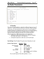
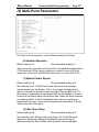
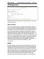
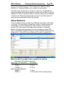
1
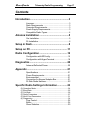
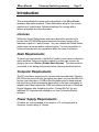
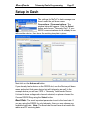
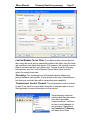
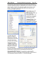
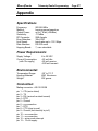
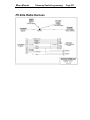
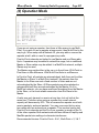
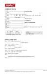
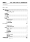
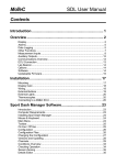
RaceGrade Telemetry Radio Programming Manual USER MANUAL Version 1.0 RaceGrade Copyright – JGM Automotive Tooling – 2011, 2012 MoTeC Systems USA and RaceGrade are registered trademarks of JGM Automotive Tooling MoTeC is a registered trademark of MoTeC Pty. The information in this document is subject to change without notice. While every effort is taken to ensure correctness, no responsibility will be taken for the consequences of any inaccuracies or omissions in this manual. 23 October, 2012 RaceGrade Telemetry Radio Programming Page Contents Introduction.........................................................3 Licenses ...................................................................3 Dash Requirements .................................................3 Computer Requirements ..........................................3 Power Supply Requirements....................................3 Compatible Radio Types ..........................................4 Antenna Installation ...........................................5 Car Installation .........................................................5 Pit Installation ...........................................................6 Setup in Dash......................................................8 Setup on PC ......................................................11 Radio Configuration .........................................12 Configuration with EZConfig ..................................15 Configuration with HyperTerminal..........................18 Diagnostics .......................................................20 Antenna Reflected Power ......................................20 Appendix ...........................................................21 Specifications .........................................................21 Power Requirements:.............................................21 Environmental: .......................................................21 Connection for Keypad Adapter Box ......................21 Pit Side Radio Harness ..........................................22 Specific Radio Settings Information...............23 (0) Operation Mode ................................................................... 24 (1) Baud Rate............................................................................ 25 (2) Call Book ............................................................................. 26 (3) Radio Parameters................................................................ 27 (5) Mutli-Point Parameters ........................................................ 31 (4) Diagnostics .......................................................................... 34 Flow Control ...........................................................34 Buffer......................................................................34 Show Statistics .......................................................35 2 RaceGrade Telemetry Radio Programming Page 3 Introduction This manual details the setup and configuration of the RaceGrade telemetry data radio modems. These data radios allow for live remote monitoring of vehicle data. Optimized settings for running with or without a repeater are also discussed. Licenses Within the United States these radios are allowed to operate in the license free 902-928 MHz spread spectrum frequency range with a maximum output of 1 watt of power. Any use outside the United States might require a license and/or reduced power. You are responsible to know and comply with any regulations within the area of operation. Dash Requirements To send real time telemetry, the MoTeC product must have its telemetry option enabled. Options currently enabled in a dash can be seen by going to the menu ‘Online | Enable Dash Options’. The dash must be connected to the laptop and powered when checking enabled options. Computer Requirements The PC must have a serial port to connect with the data radio. Physical RS-232 serial ports built into the laptop work best, but may be difficult to find on new computers. A USB-to-Serial adapter may be used instead, but might prove to be problematic depending on the type and quality of adapter used. Most require the COM port number to be set in Windows Device Manager after installing its driver. Contact MoTeC for any additional PC requirements needed to run their Telemetry Monitor software. Power Supply Requirements All radios are recommended to be wired to a 12 volt supply with a minimum current rating of 3 Amps. RaceGrade Telemetry Radio Programming Page 4 Compatible Radio Types There have been 3 variations of RaceGrade telemetry radios released. Some of the earlier ones were marked as a MoTeC USA labeled radio. Note: All three types are compatible with each other, and share the same connector pin out. Standard Mini FGR2 The mini was a smaller version of the standard, while the new FGR2 has improved noise rejection and a smaller and thinner case. RaceGrade Telemetry Radio Programming Page 5 Antenna Installation Car Installation A mobile style antenna must be fitted to the car. To improve reception and range, please follow these recommendations: The antenna should be: • outside of the car • placed on the highest surface of the car • placed in the middle of a large flat surface when possible • kept 12 inches away from any other antenna (voice or GPS) Some antennas require a ground plane. Check with the manufacture of your antenna for the best possible mounting environment. The radio itself can be mounted anywhere inside the car, but should not be exposed to excessive heat or vibration. While they are rated to 70°C, an operating temperature of less than 50°C is recommended. Reducing the power output setting will prevent over heating. The cable from the radio to the antenna should be as short as possible and the fewest number of connections to minimize any signal loss. There are many different antennas which can be used on the car, but the most popular one is the 2.5dB dipole omni. It is pictured to the left. This antenna does not require a ground plane. Non-dipole antennas all require a ground plane. It is important to electrically isolate all connections from any part of the car. As the antenna is often mounted on the body, if the connector is physically touching any steel, aluminum or carbon fiber, then there may be interference from the grounding of the antenna to the ground of the chassis. Fiberglass and Kevlar both do not conduct electricity nor block radio waves. Note: Do not over torque the antenna connection. The SMA connector coming out of the radio can be broken and bent. RaceGrade Telemetry Radio Programming Page 6 Pit Installation The pit antenna should be located as high as possible. While a 30 foot fiberglass mast is acceptable, a better solution is a 45 foot metal mast. The cable should be as short as possible, as thick as possible and with the fewest number of connections all to minimize signal loss. Antenna Selection: There are many different antennas which can be used on the pit side. Essentially 4 types exist: Pole - Omni directional so it will produce the same range in every direction. On 900 MHz, the height in feet correlates to its gain. A 3 foot antenna will have a 3dB gain. A 5 foot antenna will have a 5dB gain. A 8 foot antenna will have a 8dB gain. More gain equals more range. No ground plane is required. Pole Disk - Can be used in either the car or pit and are omni directional, so the same range in every direction. They have only a 2.5 dB gain but that is concentrated within the plane of the antenna, so it should be comparable to a 5dB pole. It does require a Disk ground plane of up to 2 square feet. Yagi - This type of antenna has a concentrated directional gain and less in other directions. It can be built with higher gains than a pole antenna, and in a more compact size. No additional ground plane required. Patch - This antenna is rarely used in motorsports. It has a high directional gain out one side, but next to nothing Fiberglass Mast Yagi Patch Metal Mast RaceGrade Telemetry Radio Programming Page 7 out the other. Sometimes used for wireless connections between two fixed points, such as the timing stand / pit and the truck / paddock. No additional ground plane required. Connections: Most connections are not waterproof, therefore wrap each connection with a plastic bag sealed at the top and open at the bottom. This will prevent water entry and allow moisture to escape. The connector itself is the antenna ground, so try to prevent the connector from touching any other grounds. A common mistake is to use a bulkhead connector through a metal plate on the timing stand for both the voice radio and telemetry radio. Separating and isolating the connectors will generate the least possible interference. Under heavy wind, the fiberglass masts will bend dramatically. Though unlikely to break, the metal mast can easily handle the heavier weight of an 8dB pole antenna, while achieving higher heights. RaceGrade Telemetry Radio Programming Page 8 Setup in Dash The settings for MoTeC’s dash manager are found under the pull down menu Connections | Communications. The window below will appear. Click the Select button and choose “Telemetry Only”. If your RS232 communications slot is already in use with another device, then leave the existing template in place. Next click on the Advanced button. If you already had a device on the RS232 slot, use the Device pull down menu and select that same device but with telemetry as well. In the example below you will see “GPS + Telemetry” listed under Device. It is best to have a diagnostic channel selected, so please choose the Comms RS232 Diag using the Select button. Baud Rate: The most important parameter to set is the baud rate. If you are using the RS232 for only telemetry, then you may choose any available baud rate. Note: The baud rate chosen here must match the radios and PC receiving data. RaceGrade Telemetry Radio Programming Page 9 Limit to Modem Carrier Rate: If you have another device which is also using the serial port by transmitting data to the dash, then the baud rate selected must match that device. It is however still possible to send data at a slower rate but not a faster rate. To slow down the telemetry transmission, use the Limit to Modem Carrier Rate check box and select the correct baud rate. Streaming: The streaming box will transmit packets without any pauses between each packet. It may speed up the rate of transmission, but also may overload the radio’s transmitting rate capability. Transmission Control Channel: The transmission control channel is used if you want to control when telemetry is sent and when it is not. See Appendix for more information on flow control. Once telemetry has been selected and the parameters have been set under communications, it will now be time to add channels to our telemetry. Navigate to the Functions | Telemetry pull down menu item. RaceGrade Telemetry Radio Programming Page 10 The telemetry setup window will appear as shown below with a list of channels selected to stream out the RS232 port in real time. The order doesn’t matter in this list. An estimated update rate is shown on the bottom. This channel rate will decrease with more channels, and increase with higher baud rates. The next tab over is the setup for End of Lap (EOL) channels. Here the order is important because this is the order in which they will appear in telemetry monitor. Transmit Point: Time from the beacon hit till transmission. This can be useful if you have spotty coverage where the beacon is located. It allows you to move the transmission point further down the track where you have solid coverage. Transmit X times: The EOL values can be repeated to make sure they get received each lap. Increasing this beyond 3 will create a noticeable hole in real time data during EOL transmission as both cannot be transmitted at the same time. Intermediate EOL Packets: It is possible to update the EOL channels more than once per lap. In the example here, 600 packets at 33.3 packets/sec results in 600/33.3 = 18 second intervals. RaceGrade Telemetry Radio Programming Page 11 Setup on PC Using the Motec Telemetry program you will need to configure the Serial Port and set the Baud Rate to match that of the radios. Select the proper COM port number for the serial port. Normally on laptops with built-in serial ports, it will be COM1. For USB-toSerial adapters, you will need to manually set the COM port number in device manager for your adapter. Once selected, use the Configure button to bring up additional parameters including baud rate. Pick the Baud rate that matches the baud rate in dash manager and the radios. Flow control should be set to None. RaceGrade Telemetry Radio Programming Page 12 Radio Configuration You may program your radio either through EZConfig, or a terminal program like HyperTerminal. HyperTerminal is included on every Windows XP installation, but is not found in Windows Vista or Win7. For those operating systems, you may use one of many shareware terminal programs available online, or EZConfig. There are three possible setups which are recommended. For all three methods, please refer to the recommended settings chart on the following page. Point-to-Point: This method is the simplest. You will have one radio setup as the Master (car radio), and the other radio setup as a Slave (pit radio). Baud rates up to 115k are supported, but 57.6k is recommended for robustness. In this method, the Call Book should contain the serial number of the other radio. Any spare radios should also be listed in the Call Book for easy replacement without the need to reprogram. All Multi-Point parameters are ignored. Car Pit Repeater: A repeater may be added in Point-to-Point mode, whereby the transmission from the Car will always go through the repeater, then to the pit lane. Car Repeater Pit RaceGrade Telemetry Radio Programming Page 13 Multi-Point with or without Repeater: This method is recommended whenever a repeater might be used. Rather than relying on a Call Book to identify which radios will talk to each other, it relies on a Network ID which is any number from 0 to 4095 but not 255. The number of repeaters must be set to 1 on each radio. The car radio is a Multi-Point Master, the pit radio a Multi-Point Slave and the repeater a Multi-Point Repeater. The repeater may be added or removed without the need to reprogram any of the radios. A repeater is an excellent way to increase telemetry coverage on larger tracks. Smaller tracks which don’t require a repeater can keep the same radio configuration, but just remove the repeater. Repeater: When powered up, the car radio will try to establish a link to both the repeater and pit radio. It is possible for the car radio to link to both at the same time. Once the car is out of range of the pit radio, it will drop that link and try to stay connected to the repeater. The pit radio having lost its link to the car will now grab data from the repeater. The repeater should always be in range of the pit radio. The pit radio will not reconnect directly to the car radio unless the car radio looses its link to the repeater and is in range of the pit. If the car radio never looses its link to the repeater, then the pit radio will always get its data through the repeater. If the car looses its link to the repeater, and the pit radio is in range, then it will link directly to it. Repeater Car Only when not connected to Car Pit It’s best to place the repeater in range of the pit, but far enough away for the car to drop its link to the repeater when its near the pit radio. This will maintain the strongest possible link while the car is traveling down the front straight near the pit radio. RaceGrade Telemetry Radio Programming Page 14 Recommended Settings: Note: When using 115k baud rate, setting (4) RF Data Rate may be set to 2. For baud rates up to 57600 setting (4) RF Data Rate must be set to 3. Flow control is always recommended whenever 115k baud rate is chosen. See the Appendix for more information about flow control. Note: In Multi-Point mode, to force the pit radio to always receive from the repeater, use the following additional settings: Subnet ID Repeater Pit / Slave RxID 0 1 TxID 1 1 Note: In Multi-Point mode, if you want the repeater to transmit data out of it’s own serial connection, then set (A) SLAVE/REPEATER to 1. RaceGrade Telemetry Radio Programming Page 15 Configuration with EZConfig Older FGR radios might not work with EZConfig. FGR2 radios require EZConfig version 3.4 or newer. EZconfig is the software program available to configure your data radios. The File pull down menu allows you to save and retrieve configurations to your computer’s hard drive. There are two buttons near the top for programming the radio and reading the configuration out of the radio. Set Operation Mode In this window, ignore all the Ethernet Options on the bottom half of the screen. Only the Modem Mode needs to be set by selecting from the pull down menu. Point-to-Point Car Radio 0 Pit Radio 1 Repeater (optional) - Multi-Point 2 3 7 RaceGrade Telemetry Radio Programming Page 16 Set Baud Rate Under most circumstances, you will want to run 57600 for the baud rate. This baud rate must match what your configuration is set to in the MoTeC product. All other settings should be left on their default as shown above. MultiPoint Parameters These settings are ignored in Point-to-Point mode. Set Master Packet Repeat, Max Slave Retry and Retry Odds all to 0. Network ID should be a unique number between 0-4095 but not 255. For Multi-Point mode with the option on the right of Repeaters choose On. For Multi-Point mode when a repeater will never be used choose Off for the Repeaters selection on the right. All other settings will be kept on default as shown in the picture above. RaceGrade Telemetry Radio Programming Page 17 Transmission Characteristics The Frequency Key must match on both radios and set to a unique number, different from other radios being used in the same area. The Max Packet Size should be set to 9 and the Min set to 0. Retry Timeout should be set to 8. RF Data Rate should be set to Normal for baud rates up to 57600 and set to High for 115k. All other settings will be kept on default as shown in the picture above. Call Book For Point-to-Point setup, the Call Book must be used. It will list the serial number of the other radio you wish to communicate to. If you have a backup radio, enter both serial numbers and choose Call All. For Multi-Point setup, the call book is not used when a Network ID is set. You may use the call book instead of Network ID but that is not recommended. RaceGrade Telemetry Radio Programming Page 18 Configuration with HyperTerminal HyperTerminal is included on every Windows XP installation, but is not included in Windows Vista or Win7. For those operating systems, you may use one of many shareware terminal programs available online, or the EZConfig software (recommended). The following describes how to setup HyperTerminal for use in programming the radio parameters. You can find HyperTerminal under: start | Programs | Accessories | Communications The “Connection Description” window appears, and you will type in a name for this connection and press OK. Note: The name here is not important, though you may save these settings for future use. In the “Connect To” window type in any area code, then select your COM port # under the Connect using pull down menu. RaceGrade Telemetry Radio Programming Page 19 The next window will be the “Com # Properties”. For the Bits per second select 19200 and Flow control to None. The 19200 is the only baud rate to which Hyper Terminal communicates with the radio and is not to be confused to the baud rate settings in the radio or dash settings. At this stage you will connect your pit harness to the radio, computer and power supply. There will be a jumper lead that extends out of the harness, this needs to be jumped (two wires shorted) to put your radio into set up mode. This can be done by wiring up a switch to the two wires, or using a small piece of wire. Once jumped your radio’s main menu should appear in Hyper Terminal and all three LEDs will light up green. Take note of the modem serial number, this will be used later when setting up your call book for the other radio. Go through each menu setting with the recommended settings. To exit setup mode, press the escape key multiple times until the three green LEDs turn off and return to their normal operating method. Note: Whenever a change is made while in HyperTerminal, a power cycle is required for the radio to accept its new settings. Do not “hot plug” radios to cycle power. RaceGrade Telemetry Radio Programming Page 20 Diagnostics In Point-to-Point, if you have one green light (CD) on both radios then they are connected and good to go. The other lights will be off, blinking red or solid red depending on the data being sent. In Multi-Point, the Car radio will never have a green light. The repeater and Pit radio should have one green light (CD). The other lights will be off, blinking red or solid red depending on the data being sent. The most common error to getting connection is not having the same baud rate set in all locations. There are four locations, dash configuration, Master radio, Slave radio and computer. All must match. Second most common is an incomplete Call Book or wrong serial numbers entered. Third is not having matching FreqKey settings. Antenna Reflected Power Another test is in Diagnostics is the Antenna Reflected Power number. This is a measure of the power or signal which gets reflected back into the radio. It is essentially a measurement of how good your antenna, wire and its connections are. The number should be 3 or less for a pit antenna, and 10 or less for the car antenna. If the number is very high such as over 50, then you have no antenna connected or a loose connection. Values less than 50 but higher than minimum point to a bad connection, heavy wire loss or improper ground plane. This value will change based on the power output of the radio. At a power setting of 10 (1 watt), the Antenna Reflected Power number will be twice that of power setting of 5 (0.5 watts). Note: A radio set to Master can report Antenna Reflected Power, but the Slave does not. Therefore when trying to test the Antenna Reflected Power you must set the radio to be Master, then power cycle the radio before a valid Antenna Reflected Power number can be read. Bench Testing It is recommended that the antenna be kept at least 23 cm away from nearby persons to satisfy FCC RF exposure requirements. Setting the Xmit power to 1 will also help. During testing, the Master (car side) will likely always require antenna. Sometimes the Slave (pit side) does not. But it is always best to run with an antenna just to be sure. A unity gain antenna is more than enough for close testing. RaceGrade Telemetry Radio Programming Appendix Specifications Frequency: Method: Output Power: Sensitivity: RF Connector: Error Detection: Link Speed: Data Interface: Hopping Bands: 902-928 MHz hopping spread spectrum up to 1 Watt (+30dBm) -110dBm SMA female 32bit CRC baud rates up to 115.2 Kbps RS-232 serial 7, user selectable Power Requirements: Supply Voltage: Current Consumption: (with 12v supply) 6 to 30 VDC ~25 mA idle ~90 mA receive ~500 mA transmit Environmental: Temperature Range: Housing Material: Weight: -20° to 75° C 6061 Aluminum 202 grams Connection: Mating connector: AS 610-35SN pin 1 – CD (carrier detect) pin 2 – TX pin 3 – RX (receive from dash transmit) pin 4 – DTR pin 5 – Ground pin 6 – no connection pin 7 – RTS pin 8 – CTS (clear to send) pin 9 – Ground (tied internally to pin 5) pin 10 – no connection pin 11 – no connection pin 12 – setup mode interrupt pin 13 – 12 volt supply Page 21 RaceGrade Telemetry Radio Programming Pit Side Radio Harness Page 22 RaceGrade Telemetry Radio Programming Page 23 Specific Radio Settings Information There are a number of settings that are controlled only by the Master and need not to match in the Slave. Point-to-Point Settings: Settings in the slave which not determined by the Master and must be set are RF Xmit Power, Slave Security, Retry Time Out and Hop Table settings (must be identical to the Master). All other settings should match. Multi-Point Settings: Baud Rate, FreqKey, Max/Min Packet Size, RF Data rate, Number of Repeaters, Network ID must all be identical. RaceGrade Telemetry Radio Programming Page 24 (0) Operation Mode If you are not using a repeater, then there is little reason to use MultiPoint. If you wish to use a repeater at some point, then Multi-Point is the way to go. When setup with a Network ID, you may add or remove the repeater at will, with no need to reprogram any radio. Point-to-Point networks are limited to one Master and one Slave radio. Up to 4 repeaters may be added to extend the range, but no additional Master or Slave radios may be added. In a MultiPoint network, multiple Slaves may be used. The Master may reside either in the car or in the pit lane. With Point-toPoint there is little difference. With Multi-Point there is a difference. In Point-to-Point, all packets are acknowledged, both from and to either the Master or Slave. In a Multi-Point network, the packets from the Master to the Slave are sent a fixed number of times and are not acknowledged by the Slave. All Slave packets are acknowledged or retransmitted until they are acknowledged by the Master. So in a MultiPoint network, you can have maximum throughput from the Master to the Slave, or the most reliable connection from the Slave to the Master. A radio may only transmit or receive at any time, but not both at the same time. Therefore when using a repeater the overall network capacity will decrease by 50%. This is because the repeater must both receive packets, and send packets. You may overcome this by using two radios with two antennas as a repeater. This involves having two Point-to-Point networks and the Rx of one repeater is wired into the Tx of the other repeater. Both networks should have different FreqKey and Max/Min packet size settings to eliminate interference. Recommended choices: Point-to-Point = 0 & 1, Mutli-Point = 2, 3 & 7 RaceGrade Telemetry Radio Programming Page 25 (1) Baud Rate The communications rate of data going in and out of the radios. Higher numbers equal faster data rates and more throughput. The radios themselves will try to communicate at 230k, but the actual throughput is much less due to overhead in handshaking and frequency hopping. Under normal race track conditions the maximum data throughput is around 80-90k. Therefore 57600 is the highest recommended rate. Under a perfect bench testing environment, 115200 is possible but will break down upon any interference which causes it to loose its connection. Once a loss of connection is experiences, the radios will never catch back up and empty its buffer. This will result in a percentage of bad packets until the connection is dropped, buffer cleared, and reconnected. Freewave recommends flow control on any baud rate higher than 38400. If your environment is very noisy, dropping the baud rate down to 38400 will help prevent buffer overflow, which is a cause of bad packets. See Flow Control in the Appendix for further information. All the other parameters in this menu should be kept at their default values, as shown below. None of them are useful in our situation. RaceGrade Telemetry Radio Programming Page 26 (2) Call Book The call book is one level of security. It is required with Point-to-Point networks. Though not recommended, the call book can be used in Multi-Point when a Network ID is not being used. For most installations of Multi-Point this call book should remain empty. The call book lists each serial number in which the radio can establish a connection with. Enter the row you wish to add, type in the serial number of the Slave. If a repeater if being used then type that in after, followed by 000-0000 to signal the end of your entry or use the ESC key. There are a number of entry rows, which can contain multiple Slaves or Slaves & Repeaters. The row which is called is found near the top under “Entry to Call is XXX”. You may change which row is called by using the C entry at the prompt and selecting which row to use. If set to Call All, then the Master will connect to the first slave it can find and no others. With Call All in the call book, a master will not connect with any slaves through repeaters. Call All is useful in a Point-to-Point situations where you want to have backup radios ready to go. Repeaters need to only be listed in the Master call book along with the Slave serial number. The repeater is not required in the Slave call book. The Slave Call book only has to have the Master serial number in it, as the repeater appears invisible to it. RaceGrade Telemetry Radio Programming Page 27 (3) Radio Parameters (0) FreqKey There are 15 hopping patterns, selected via different frequency keys (09 and A-E). This is to minimize interference with other radios operating in the same area. Spread spectrum radios work by communicating on multiple frequencies, and therefore they are never on a single frequency for very long. If two radios get onto the same frequency, having a different FreqKey setting will guarantee the next hop would be to different frequencies. Additional separation can be gained by • Adjusting the Max and Min packet sizes, therefore changing how long a radio stays on one frequency. • Limiting the frequencies a radio can use to hop through. Hop Settings: Select FreqKey F to gain access. Normally not used. (0) Hop Table Version North America Australia Selection Band 0 902 - 928 MHz 1 915 - 928 MHz 2 903.744 - 926.3232 Taiwan 3 916 - 920 MHz New Zealand 4 921 - 928 MHz 5 902-928 MHz w/o 911-919 MHz Brazil 6 902 - 915 MHz Do not use FreqKey 14 (E) with hop tables 1, 3 or 4. RaceGrade Telemetry Radio Programming Page 28 (1) Hop Table Size Defines how many channels will be used within a given network (50-112). Normal setting is 112. (2) Hop Table Version Do not use, not available on 900 MHz radios. (3) Frequency Zone Normally not used. (1 & 2) Max / Min Packet Size Default setting Max 8 Min 9 Recommended setting Max 9 Min 0 In point to point mode, the packet size will not have much impact on throughput unless 115.2k baud rate is being utilized. Total throughput can be improved if the packet size matches what is being transmitted. However, the packets sent out via telemetry from MoTeC devices are often longer than the maximum packet setting in the radio. Therefore to optimize throughput it is desirable to have the largest possible packet size on each hop. While setting the Min to 9 can lengthen the maximum packet size, it also increases the minimum packet size. This is bad for empty packets which the Slave transmits to the Master in Point-to-Point. If small amounts of data are sent and large packets are selected then there will be some wasted time in sending large packets with little data. Therefore the minimum packet size should be kept small. This also keeps the Slave packets (which aren’t transmitting any data) to be as small as possible improving throughput of the Master to the Slave. The following is a rough calculation (ie: not quite the same as in Dash Manager). Total packet size is: characters_per_packet = 12 + 2 * number_of_channels Running with RS232 settings of 8-N-1 will result in 9 bits per character. The time for each packet is: packet_time = characters_per_packet * 9 / comms_baud_rate + small overhead between packets (minimal when streaming is checked) Using the packet time, a message update rate can be calculated: update rate = 1 / packet_time RaceGrade Telemetry Radio Programming Page 29 (3) Xmit Rate Default setting is 1 Recommended setting is 1 The setting for normal operation is 1. When set to 0 the radios will transmit continuously regardless of any actual data. This is used in diagnostics to determine signal strength based off the CTS light. (4) RF Data Rate Default setting is 3 Recommended setting is 3 or 2 This parameter is the rate of communications between the radios, not to be confused with the serial baud rate into and out of the radio. This rate must be higher than the serial baud rate in order to handle the overhead during handshaking and frequency hopping. A setting of 2 can result in higher throughput, and should only be used when the serial baud rate is 115k. A setting of 3 should be used when a solid data link is preferred over throughput and any time the baud rate is lower than 115k. 1 = 230.4k 2 = 153.6k 3 = 115.2k (5) RF Xmit Power Default setting is 10 Recommended setting is 10 This is the power output of the radios where a value of 10 equals 1 watt (normal setting). During bench testing, it is recommended to set this value to 1. (6) Slave Security Default setting is 0 (enabled) Recommended setting is 0 Not normally used. A feature that allows the Slave to accept data from a Master which is not included in the Slave call book. The Slave must be included in the Master call book. Has no effect in Multi-Point networks when a Network ID is used. (7) RTS to CTS Default setting is 0 (disabled) Recommended setting is 0 Not normally used. This pass through control enables the RTS (readyto-send) line on the Master to control the CTS (clear-to-send) line of the Slave. Do not use this function with baud rates above 38.4k. RaceGrade Telemetry Radio Programming Page 30 (8) Retry Time Out Default setting is 255 Recommended setting is 8 or 151 The delay time until a radio will drop its connection and attempt to reestablish at the beginning of the hopping pattern. Time is based on packet size. This is important when using a Multi-Point repeater. When the car looses contact with one of the radios, it must drop that connection quickly in order to find the other radio. If set to 255 then it will take a long time to switch connection between radios. A lower setting allows a poor link to break in search of a stronger one. Even in a Point-to-Point mode, a setting of 151 is recommended in areas where several radios exist and interference can be a problem. (9) Lowpower mode Default setting is 0 (disabled) Recommended setting is 0 Not normally used. Can lower power draw on a Slave radio. (A) High Noise Default setting is 0 Recommended setting is 0 Not normally used. Useful only for determining if out of band interference is affecting the radio link. A setting of 1 will provide a reduction of gain in the radio, thereby reducing any effect of out of band noise. A lower signal value will result, but a much lower noise value should also occur. This setting will reduce the range of the radios. (B) MCU Speed Default setting is 0 Recommended setting is 0 Not normally used. This is the speed of the main processor. May be set to 1 only when RF Data Rate equals 2, but typically not needed. Will generate more heat inside the radio. (C) Remote LED Default setting is 0 Recommended setting is 0 Not normally used. Used to enable remote LEDs through the separate diagnostic port. This option set to 2 may be used in repeaters to save power by turning off the LEDs. RaceGrade Telemetry Radio Programming Page 31 (5) Mutli-Point Parameters For Point-to-Point operation, most of these settings do nothing. (0) Number Repeaters Default setting is 1 Recommended setting is 1 When not using a repeater, set this to 0 for increased throughput above 57.6k baud rate. When using a repeater or setup to use one but not using one, set this to 1 and limit the baud rate to no more than 57.6k. (1) Master Packet Repeat Default setting is 2 Recommended setting is 0 Not normally used. In Multi-Point mode, Slaves do acknowledge transmissions from the Master. This is to increase throughput and reduce overhead for situations where multiple Slaves might exist. For this reason, it is possible to repeat packets from the Master in order to be sure all the Slaves have received the data. When the Slave receives an identical packet, it will be discarded. When set to 0, packets are transmitted only once, when set to 9 packets are transmitted 10 times. Valid entries are 0 through 9. (2) Max Slave Retry Default setting is 9 Recommended setting is 0 Not normally used. Defines how many times (0 to 9) the Slave will attempt to retransmit a packet to the Master before backing off (determined by the Retry Odds) until the packet is acknowledged. RaceGrade Telemetry Radio Programming Page 32 (3) Retry Odds Default setting is 9 Recommended setting is 0 Not normally used. While packets from the Master to the Slave are not acknowledged, packets from the Slave to the Master are. If multiple Slaves attempt to connect to the Master at the same time, the Max Slave Retry and Retry Odds are used to determine if the Slave will retransmit its data in hopes of getting through to the Master. (4) DTR Connect Default setting is 0 Recommended setting is 0 Not normally used. When set to 0, the Slave will transmit data when it is received. When set to 1 the Slave will form a direct link for data when the DTR line is high. When set to 2 the Slave will transmit in bursts. (5) Repeater Frequency Default setting is 0 Recommended setting is 0 Not normally used. When set to 1, the repeater can use a different FreqKey than the Master. This can be used when multiple repeaters overlap their area of responsibility. (6) Network ID Default setting is 255 Recommended setting is 0-4095 The default setting of 255 instructs the radio to use its call book. Any other number will instruct the radio to use that number as a Network ID rather than the call book, connecting to any radio on that ID. Any number between 0 to 4095 may be used. Since the radio does not use a call book, radios may be replaced without reprogramming of any radio, and repeaters may be added or removed as needed. (8) MultiMaster Sync Default setting is 0 Recommended setting is 0 Not normally used. (9) 1 PPS Enable/Delay Default setting is 255 Not normally used. Recommended setting is 255 RaceGrade Telemetry Radio Programming Page 33 (A) Slave / Repeater Default setting is 0 Recommended setting is 0 or 1 When set to 1 with operation mode set to 7, the repeater radio will act like a slave and transmit data out the RS232 port (B) Diagnostics Default setting is 0 Recommended setting is 0 Not normally used. (C) SubNet ID Default setting is Disabled Recommended setting is Disabled Not normally used. Can be used to force a specific path through specific Repeaters. To force the pit radio to always receive from the repeater, use the following additional settings: Subnet ID Repeater Pit / Slave RxID 0 1 TxID 1 1 (D) Radio ID Default setting is Not Set Recommended setting is Not Set Not normally used. Can be set to identify a radio in diagnostics mode. (E) Local Access Default setting is 0 Recommended setting is 0 Not normally used. (F) Radio Name Default setting is blank Recommended setting is blank Not normally used. Used to set a unique 20 character radio name. RaceGrade Telemetry Radio Programming Page 34 (4) Diagnostics FGR and Mini radios will also report the Transmit Current of the radio. FGR2 radios will not. Flow Control True flow control cannot be accomplished with any MoTeC product in their current states of software development. A work around hack for flow control can be created by utilizing the CTS (clear to send) line as a transmission control line in the telemetry setup in the dash. The CTS line of the radio should be connected up to a digital input. Then this digital input channel will be used as the transmission control line under the advanced telemetry settings. It will help to minimize the buffer overflow, but not entirely prevent it. The CTS line is updated at the radio side after every Byte of data. But on the MoTeC side, the transmission control line only updates at 50 Hz. Therefore a time delay exists in the radio saying “stop sending” and the MoTeC actually stopping its transmission which will result in a few bad packets. This archaic flow control is still useful at rates higher than 38400 or in noisy environments. Buffer Each radio has an internal buffer which is 2000 Bytes long. When the throughput of data between the radios becomes slower than the data streaming into the radio, this buffer will fill up. When the throughput of data between the radios is faster than the incoming data it will empty. When the buffer gets full, new incoming data is written over the existing data in the buffer, starting from the beginning of the buffer. So a later packet’s data will be written into an earlier packet of data. The radio then sends out mixed data. Because each packet of data has a checksum at the end, the packet will be denied in Telemetry Monitor RaceGrade Telemetry Radio Programming Page 35 because the checksum failed. This is easily seen under the Show Statistics in Telemetry Monitor in the number of bad packets. The buffer gets cleared upon a full drop in radio link. To facilitate this happening quickly when having spotty coverage, set the Retry Time Out setting to 8. This will cause the radio to drop its existing link and attempt a fresh re-link. When the radios finally reconnect, the buffer starts off empty and no bad packets will stream through. Show Statistics Telemetry Monitor does provide some statistical information of the data it receives. This information includes the number of good packets and bad packets. It can be displayed as a total number, or the rate per second. This rate number is averaged from the start of Telemetry Monitor. So when making changes it is best to close and restart TM when evaluating throughput. Always try to start TM when data is actively being sent in, or else your rate numbers will include time spent idle. Maximum Data Throughput Values (packets per second) (based off 128 real time channels) Baud Rate / RF Data Rate Bandwidth Point-to-Point 57600 / 3 20.9 Hz 115200 / 2 41.5 Hz Multi-Point with Repeater 38400 / 3 12.5 Hz 57600 / 3 16.4 Hz (and 4.0 Hz of bad packets)