1
Sun Blade T6340 Server Module
Service Manual
Part No. 820-3902-12
April 2010, Revision A
Copyright © 2008, 2010, Oracle and/or its affiliates. All rights reserved.
This software and related documentation are provided under a license agreement containing restrictions on use and disclosure and are
protected by intellectual property laws. Except as expressly permitted in your license agreement or allowed by law, you may not use, copy,
reproduce, translate, broadcast, modify, license, transmit, distribute, exhibit, perform, publish, or display any part, in any form, or by any
means. Reverse engineering, disassembly, or decompilation of this software, unless required by law for interoperability, is prohibited.
The information contained herein is subject to change without notice and is not warranted to be error-free. If you find any errors, please report
them to us in writing.
If this is software or related software documentation that is delivered to the U.S. Government or anyone licensing it on behalf of the U.S.
Government, the following notice is applicable:
U.S. GOVERNMENT RIGHTS. Programs, software, databases, and related documentation and technical data delivered to U.S. Government
customers are "commercial computer software" or "commercial technical data" pursuant to the applicable Federal Acquisition Regulation and
agency-specific supplemental regulations. As such, the use, duplication, disclosure, modification, and adaptation shall be subject to the
restrictions and license terms set forth in the applicable Government contract, and, to the extent applicable by the terms of the Government
contract, the additional rights set forth in FAR 52.227-19, Commercial Computer Software License (December 2007). Oracle USA, Inc., 500
Oracle Parkway, Redwood City, CA 94065.
This software or hardware is developed for general use in a variety of information management applications. It is not developed or intended for
use in any inherently dangerous applications, including applications which may create a risk of personal injury. If you use this software or
hardware in dangerous applications, then you shall be responsible to take all appropriate fail-safe, backup, redundancy, and other measures to
ensure the safe use. Oracle Corporation and its affiliates disclaim any liability for any damages caused by use of this software or hardware in
dangerous applications.
Oracle and Java are registered trademarks of Oracle and/or its affiliates. Other names may be trademarks of their respective owners.
AMD, Opteron, the AMD logo, and the AMD Opteron logo are trademarks or registered trademarks of Advanced Micro Devices. Intel and Intel
Xeon are trademarks or registered trademarks of Intel Corporation. All SPARC trademarks are used under license and are trademarks or
registered trademarks of SPARC International, Inc. UNIX is a registered trademark licensed through X/Open Company, Ltd.
This software or hardware and documentation may provide access to or information on content, products, and services from third parties.
Oracle Corporation and its affiliates are not responsible for and expressly disclaim all warranties of any kind with respect to third-party content,
products, and services. Oracle Corporation and its affiliates will not be responsible for any loss, costs, or damages incurred due to your access
to or use of third-party content, products, or services.
Copyright © 2008, 2010, Oracle et/ou ses affiliés. Tous droits réservés.
Ce logiciel et la documentation qui l’accompagne sont protégés par les lois sur la propriété intellectuelle. Ils sont concédés sous licence et
soumis à des restrictions d’utilisation et de divulgation. Sauf disposition de votre contrat de licence ou de la loi, vous ne pouvez pas copier,
reproduire, traduire, diffuser, modifier, breveter, transmettre, distribuer, exposer, exécuter, publier ou afficher le logiciel, même partiellement,
sous quelque forme et par quelque procédé que ce soit. Par ailleurs, il est interdit de procéder à toute ingénierie inverse du logiciel, de le
désassembler ou de le décompiler, excepté à des fins d’interopérabilité avec des logiciels tiers ou tel que prescrit par la loi.
Les informations fournies dans ce document sont susceptibles de modification sans préavis. Par ailleurs, Oracle Corporation ne garantit pas
qu’elles soient exemptes d’erreurs et vous invite, le cas échéant, à lui en faire part par écrit.
Si ce logiciel, ou la documentation qui l’accompagne, est concédé sous licence au Gouvernement des Etats-Unis, ou à toute entité qui délivre la
licence de ce logiciel ou l’utilise pour le compte du Gouvernement des Etats-Unis, la notice suivante s’applique :
U.S. GOVERNMENT RIGHTS. Programs, software, databases, and related documentation and technical data delivered to U.S. Government
customers are "commercial computer software" or "commercial technical data" pursuant to the applicable Federal Acquisition Regulation and
agency-specific supplemental regulations. As such, the use, duplication, disclosure, modification, and adaptation shall be subject to the
restrictions and license terms set forth in the applicable Government contract, and, to the extent applicable by the terms of the Government
contract, the additional rights set forth in FAR 52.227-19, Commercial Computer Software License (December 2007). Oracle America, Inc., 500
Oracle Parkway, Redwood City, CA 94065.
Ce logiciel ou matériel a été développé pour un usage général dans le cadre d’applications de gestion des informations. Ce logiciel ou matériel
n’est pas conçu ni n’est destiné à être utilisé dans des applications à risque, notamment dans des applications pouvant causer des dommages
corporels. Si vous utilisez ce logiciel ou matériel dans le cadre d’applications dangereuses, il est de votre responsabilité de prendre toutes les
mesures de secours, de sauvegarde, de redondance et autres mesures nécessaires à son utilisation dans des conditions optimales de sécurité.
Oracle Corporation et ses affiliés déclinent toute responsabilité quant aux dommages causés par l’utilisation de ce logiciel ou matériel pour ce
type d’applications.
Oracle et Java sont des marques déposées d’Oracle Corporation et/ou de ses affiliés.Tout autre nom mentionné peut correspondre à des
marques appartenant à d’autres propriétaires qu’Oracle.
AMD, Opteron, le logo AMD et le logo AMD Opteron sont des marques ou des marques déposées d’Advanced Micro Devices. Intel et Intel
Xeon sont des marques ou des marques déposées d’Intel Corporation. Toutes les marques SPARC sont utilisées sous licence et sont des marques
ou des marques déposées de SPARC International, Inc. UNIX est une marque déposée concédée sous licence par X/Open Company, Ltd.
Ce logiciel ou matériel et la documentation qui l’accompagne peuvent fournir des informations ou des liens donnant accès à des contenus, des
produits et des services émanant de tiers. Oracle Corporation et ses affiliés déclinent toute responsabilité ou garantie expresse quant aux
contenus, produits ou services émanant de tiers. En aucun cas, Oracle Corporation et ses affiliés ne sauraient être tenus pour responsables des
pertes subies, des coûts occasionnés ou des dommages causés par l’accès à des contenus, produits ou services tiers, ou à leur utilisation.
Please
Recycle
Contents
Using This Documentation
1.
Sun Blade T6340 Server Module Product Description
1.1
Component Overview
1.1.1
1.2
Multicore Processor Information
1–10
1.2.2
1–10
To Create a Simple Volume Using Just One HDD
Sun Blade RAID 0/1 G2 Expansion Module
1.3
Finding the Serial Number
1.4
Additional Service Related Information
Diagnostics
1–10
Sun Blade RAID 5 Expansion Module
▼
1–1
1–1
Support for RAID Storage Configurations
1.2.1
2.
xi
1–12
1–12
1–15
2–1
2.1
Sun Blade T6340 Server Module Diagnostics Overview
2.2
Memory Configuration and Fault Handling
2.2.1
2.3
111
Memory Configuration
2–6
2–6
2.2.1.1
FB-DIMM Installation Rules
2.2.1.2
Memory Fault Handling
2.2.1.3
Troubleshooting Memory Faults
Interpreting System LEDs
2–1
2–7
2–10
2–10
2–11
iii
2.3.1
Front Panel LEDs and Buttons
2.3.2
Power and Reset Buttons
2–14
2.4
Using ILOM for Diagnosis and Repair Verification
2.5
Using the ILOM Web Interface For Diagnostics
2.5.1
2.6
2.7
Displaying System Faults
2–14
2–17
2–18
2.5.1.1
Viewing Fault Status Using the ILOM Web Interface
19
2.5.1.2
Viewing Fault Status Using the ILOM CLI
2–
2–21
2.5.2
Displaying the Environmental Status with the ILOM CLI
2.5.3
Displaying the Environmental Status and Sensor Readings with the
ILOM Web Interface 2–22
2.5.4
Displaying FRU Information
2–21
2–23
2.5.4.1
Using the ILOM Web Interface to Display FRU
Information 2–23
2.5.4.2
Using the CLI to Display FRU Information
Running POST
2–24
2–27
2.6.1
Controlling How POST Runs
2.6.2
Changing POST Parameters
2–27
2–30
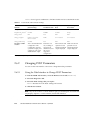
2.6.2.1
Using the Web Interface to Change POST Parameters
30
2.6.2.2
Using the CLI to Change POST Parameters
2.6.3
Interpreting POST Messages
2.6.4
Clearing POST Detected Faults
2–33
2–34
2–35
2.6.4.1
Clearing Faults With the Web Interface
2.6.4.2
Clearing Faults With the ILOM CLI
2.6.4.3
Clearing Faults Manually with ILOM
2.6.4.4
Clearing Hard Drive Faults
2–36
2–37
2–38
2–38
Using the Solaris Predictive Self-Healing Feature
2.7.1
iv
2–11
2–38
Identifying Faults With the fmadm faulty and fmdump
Commands 2–39
Sun Blade T6340 Server Module Service Manual • April 2010
2–
2.8
2.9
2.11
Using the fmdump Command
3.2
2.7.3
Clearing the PSH Fault From the ILOM Logs
2–42
2–43
Collecting Information From Solaris OS Files and Commands
2.8.1
Checking the Message Buffer
2.8.2
Viewing the System Message Log Files
2–44
2–44
2–44
Managing Components With Automatic System Recovery Commands
45
2–
Displaying System Components With the show /SYS Command
2–47
Exercising the System With SunVTS
2–48
2.10.1
Checking SunVTS Software Installation
2.10.2
Exercising the System Using SunVTS Software
Resetting the Password to the Factory Default
2–48
2–49
2–52
To Reset the Root Password to the Factory Default
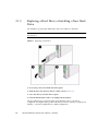
Hot-Plugging a Hard Drive
2–52
3–1
3–2
3.1.1
Rules for Hot-Plugging
3.1.2
Removing a Hard Drive
3.1.3
Replacing a Hard Drive or Installing a New Hard Drive
Adding PCI ExpressModules
3–2
3–2
Safety Information
3–4
3–5
Replacing Cold-Swappable Components
4.1
2–39
2–40
Replacing Hot-Swappable and Hot-Pluggable Components
3.1
4.
2.7.1.2
Clearing PSH Detected Faults
2.11.1
3.
Using the fmadm faulty Command
2.7.2
2.9.1
2.10
2.7.1.1
4–1
4–1
4.1.1
Safety Symbols
4–2
4.1.2
Electrostatic Discharge Safety
4–2
4.1.2.1
Using an Antistatic Wrist Strap
4.1.2.2
Using an Antistatic Mat
4–2
4–3
Contents
v
4.2
4.3
4.4
4.5
4.6
Common Procedures for Parts Replacement
4.2.1
Required Tools
4.2.2
Shutting Down the System
4.2.3
Shutting Down the Server Module Using the ILOM Web Interface
4–4
4.2.4
Shutting Down the Server Module Using the ILOM CLI
4.2.5
Preparing to Remove the Server Module
4.8
vi
4–3
Removing and Replacing DIMMs
4–3
4–6
4–6
4–10
4.3.1
Removing the DIMMs
4–10
4.3.2
Replacing the DIMMs
4–13
Removing and Replacing the Service Processor
4.4.1
Removing the Service Processor
4–14
4.4.2
Replacing the Service Processor
4–15
4–14
Removing and Replacing the Service Processor Battery
4.5.1
Removing the Service Processor Battery
4–16
4.5.2
Replacing the Service Processor Battery
4–17
4–16
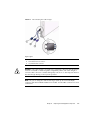
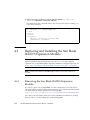
Replacing and Installing the Sun Blade RAID 5 Expansion Module
4–18
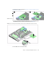
4.6.1
Removing the Sun Blade RAID 5 Expansion Module
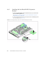
4.6.2
Installing the Sun Blade RAID 5 Expansion Module
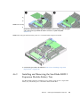
4.6.3
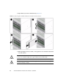
Installing and Removing the Sun Blade RAID 5 Expansion Module
Battery Tray 4–23
4.6.4
4.7
4–3
4–18
4–21
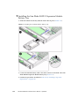
▼
Installing the Sun Blade RAID 5 Expansion Module Battery
Tray 423
▼
Removing the Sun Blade RAID 5 Expansion Module Battery
Tray 424
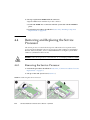
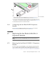
Configuring the Sun Blade RAID 5 Expansion Module
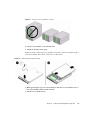
Replacing the Sun Blade G2 RAID 0/1 Expansion Module
4–25
4–25
4.7.1
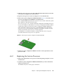
Removing the Sun Blade G2 RAID 0/1 Expansion Module
4.7.2
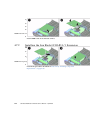
Installing the Sun Blade G2 RAID 0/1 Expansion Module
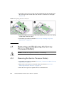
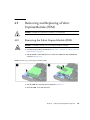
Removing and Replacing a Fabric ExpressModule (FEM)
Sun Blade T6340 Server Module Service Manual • April 2010
4–27
4–25
4–26
4.8.1
Removing the Fabric ExpressModule (FEM)
4.8.2
Replacing a Fabric ExpressModule (FEM)
4.9
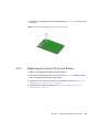
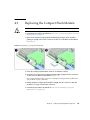
Replacing the Compact Flash Module
4.10
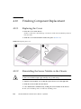
Finishing Component Replacement
4–28
4–29
4–30
4.10.1
Replacing the Cover
4.10.2
Reinstalling the Server Module in the Chassis
A. Specifications
4–27
4–30
4–30
A–1
A.1
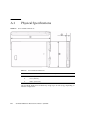
Physical Specifications
A–2
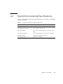
A.2
System Environmental Specifications
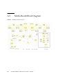
A.3
Motherboard Block Diagram
A–3
A–4
B. Creating a Bootable Array With the Sun Blade RAID 5 Expansion Module
B.1
About Creating a Bootable Array on a SPARC System
B.2
Creating a Bootable Array Task Map
B.3
Modifying the Miniroot Directory On the Install Server
▼
B.4
B.6
B–2
B–2
B–3
B-4
Modifying the Product Installation Directory on the Install Server
▼
B.5
To Modify the Miniroot Directory
To Modify the Product Installation Directory
B–6
▼
To Create a Logical Drive Using a Network Install Server
▼
To Create a Logical Drive Without a Network Install Server
▼
To Label the Newly Created Logical Drive
▼
To Delete a Logical Drive on the REM
B.6.1
B–5
B-5
Building a Logical Drive on Which to Install the Solaris OS
Next Steps
B–1
B-6
B-8
B-10
B-11
B–11
Additional Information
B–11
C. Installing the Solaris OS and the Sun Blade RAID 5 Expansion Module Driver
C–1
C.1
Preparing to Install the Solaris OS
C–1
Contents
vii
▼
C.2
Next Steps
Additional Information
D.1
Features
D.2
Video Formats
C–4
D–1
D–1
D–2
D.2.1
Obtaining Available Screen Resolutions
D.2.2
Supported Video Formats
D–2
D.3
Sun OpenGL for Solaris Software
D–3
D.4
Man Pages
D.5
Optional Video Output
D.6
Default Color Depth
D.7
Checking Device Configuration
D.8
HD15 Video Output Port
E. Connector Pinouts
D–2
D–3
D–5
D–5
D–6
D–8
E–1
E.1
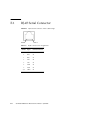
RJ-45 Serial Connector
E.2
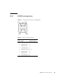
USB Connectors
E.3
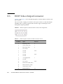
HD15 Video Output Connector
E.4
Using the Cable Dongle
E–2
E–3
E–4
E–5
F. ALOM CMT Reference Information
F–1
Switching Between the System Console and ALOM CMT and ILOM Shells
F–2
F.1.1
F.2
C-
C–4
D. XVR-50 Graphics Accelerator
F.1
C–2
To Install the RAID 5 Expansion Module Driver With the Solaris OS
2
C.3.1
viii
C-1
Installing the RAID 5 Expansion Module Driver With the Solaris OS
▼
C.3
To Prepare to Install the Solaris OS
Switching From the ALOM CMT Shell to the ILOM Shell
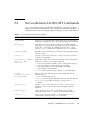
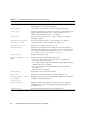
Service-Related ALOM CMT Commands
Sun Blade T6340 Server Module Service Manual • April 2010
F–3
F–2
G. ILOM Reference Information
G.1
G–1
Creating an ALOM CMT Shell
G–1
G.1.1
Creating an ALOM CMT Compatibility Shell
G–2
G.1.2
Connecting to the Host Console With SSH
G.1.3
Switching Between the ALOM CMT Shell and the Host Console
G–4
G.1.4
Returning to the ILOM CLI
G–3
G–4
G.2
Switching Between the ILOM CLI and ALOM CMT Compatibility Shell
G–5
G.3
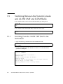
Switching Between the System Console and ILOM
G.4
Connecting to the Server Module Service Processor From the Chassis CMM
Service Processor G–6
Index
G–6
Index–1
Contents
ix
x
Sun Blade T6340 Server Module Service Manual • April 2010
Using This Documentation
This manual provides information to about servicing the Sun Blade T6340 server
module from Oracle. This manual also describes how to add components such as
hard drives and memory.
This manual is written for technicians, service personnel, and system administrators
who service and repair computer systems.
xi
How This Book Is Organized
This manual is organized into the following chapters:
Chapter 1 describes the main features of the Sun Blade T6340 server module.
Chapter 2 describes diagnostics procedures and related information.
Chapter 3 explains how to remove and replace hot-pluggable hard drives.
Chapter 4 describes how to remove and replace components that cannot be hotswapped.
Appendix A provides server specifications.
Appendix B describes how to create a bootable RAID array
Appendix C describes how to install the Solaris OS on a bootable RAID array.
Appendix D provides information about the onboard XVR-50 graphics.
Appendix E provides pinout information for the dongle cable.
Appendix F provides reference information about the ALOM CMT Compatibility
shell.
Appendix G provides additional information about ILOM and ALOM use.
xii
Sun Blade T6340 Server Module Service Manual • April 2010
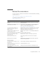
Related Documentation
You can view, print, or purchase a broad selection of Sun documentation, including
localized versions, at:
http://docs.sun.com/app/docs/prod/blade.t6340
To find other product documents, go to:
http://docs.sun.com
Document Title
Description
Sun Blade T6340 Server Module Product Notes,
820-3901
Important late-breaking information about the server module
and related software.
Sun Blade T6340 Server Module Installation and Basic information about installing, powering on, and installing
Administration Guide, 820-3900
software. If you purchased hard drives with preinstalled
software you can also find information here:
http://www.sun.com/software/preinstall
Sun Integrated Lights Out Manager 2.0
Supplement for Sun Blade T6340 Server
Modules, 820-3904
ILOM information specific to the UltraSPARC and the Sun Blade
T6340 server module. Provides command comparisons of the
ALOM CMT and ILOM CLI command sets.
Sun Blade T6340 Server Module Safety and
Compliance Manual, 820-2387
module.
Important safety information for the Sun Blade T6340 server
Chassis Documentation (Refer to the documents for your specific modular system chassis.)
Integrated Lights Out Manager ILOM
Administration Guide
ILOM information specific to the modular system chassis.
Modular System Product Notes
Late-breaking information about the chassis and related
software.
Modular System Service Manual
Component removal and replacement procedures, diagnostics
information and specifications.
Software Documentation
Sun Integrated Lights out Manager 2.0 User’s
Guide, 820-1188
Advanced Lights Out Manager (ALOM) CMT software.
Configuring Jumpstart Servers to Provision Sun Configuring JumpStart™ servers.
x86-64 Systems, 819-1962-10
Solaris 10 8/07 Installation Guide: NetworkBased Installations
Setting up network-based installations and JumpStart servers.
Using This Documentation
xiii
Document Title
Description
Sun VTS 7.0 User’s Guide, 820-0012
Testing the server module, and creating custom hardware tests.
Beginner’s Guide to LDoms: Understanding and Learning about LDoms principles.
Deploying Logical Domains, 820-0832
Solaris Operating System documentation
All information related to Solaris system administration
commands and features. Go to http://www.docs.sun.com
Documentation, Support, and Training
These web sites provide additional resources:
Sun Function
URL
Documentation
http://docs.sun.com/
Support
http://www.sun.com/support/
Training
http://www.sun.com/training/
Documentation Feedback
Submit comments about this document by clicking the Feedback[+] link at
http://docs.sun.com. Include the title and part number of your document with
your feedback:
Sun Blade T6340 Server Module Service Manual, part number 820-3902-12.
xiv
Sun Blade T6340 Server Module Service Manual • April 2010
CHAPTER
1
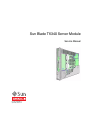
Sun Blade T6340 Server Module
Product Description
This chapter provides an overview of the features of the Sun Blade T6340 Server
Module. (A server module is also known as a blade.)
The following topics are covered:
1.1
■
Section 1.1, “Component Overview” on page 1-1
■
Section 1.2, “Support for RAID Storage Configurations” on page 1-10
■
Section 1.3, “Finding the Serial Number” on page 1-12
■
Section 1.4, “Additional Service Related Information” on page 1-15
Component Overview
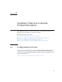
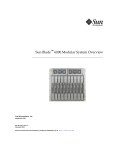
FIGURE 1-1, FIGURE 1-2, and FIGURE 1-3 show the main Sun Blade T6340 components
and some basic connections to the chassis. For information about connectivity to
system fans, PCI ExpressModules, Ethernet modules, and other components, see the
chassis documentation at:
http://docs.sun.com/app/docs/prod/blade.t6340
1-1
FIGURE 1-1
Sun Blade T6340 Server Module With Chassis
TABLE 1-1 lists the Sun Blade T6340 server module features. TABLE 1-2 lists some of
chassis input-output features.
1-2
Sun Blade T6340 Server Module Service Manual • April 2010
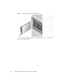
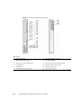
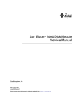
FIGURE 1-2
Front and Rear Panels
Figure Legend
1
White Locator LED
7
Universal Connector Port (UCP)
2
Blue Ready to Remove LED
8
Green Drive OK LED
3
Amber Service Action Required LED
9
Amber Drive Service Action Required LED
4
Green OK LED
10
Blue Drive Ready to Remove LED
5
Power Button
11
Chassis power connector
6
Reset Button (for service use only)
12
Chassis data connector
Chapter 1
Sun Blade T6340 Server Module Product Description
1-3
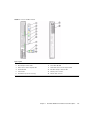
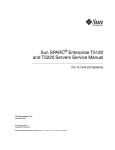
FIGURE 1-3
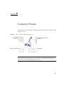
Cable Dongle Connectors
Figure Legend
1
USB 2.0 (2) connectors
2
RJ-45 Virtual Console connector
3
15-pin VGA Female connector
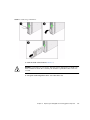
Note – Insert the connector straight into the server module.
The cable dongle is for temporary connections only. The cable dongle has not been
evaluated for electromagnetic compatibility (EMC).
The cable dongle or server module connectors could be damaged by closing rack
doors or other impacts.
Remove the cable dongle during normal system operation.
Caution – If you are using the older 4-cable dongle (UCP-4), do not use the RJ-45
connector with the Sun Blade T6340 server module. Use the DB-9 connector for serial
connections.
1-4
Sun Blade T6340 Server Module Service Manual • April 2010
TABLE 1-1
Sun Blade T6340 Server Module Features
Feature
Description
Processor
Two UltraSPARC T2 Plus multicore processors with 4MB L2 cache. Can execute up to 128
threads.
Memory
32 slots for fully buffered DIMMs (FB-DIMM), 667 MHz:
• 1 Gbyte (32 Gbyte maximum)
• 2 Gbyte (64 Gbyte maximum)
• 4 Gbyte (128 Gbyte maximum)
• 8 Gbyte (256 Gbyte maximum)
Internal hard drives Up to two hot-pluggable 2.5-inch hard drives.
• SFF SAS 73 Gbyte, 15k rpm, and 10k rpm
• SFF SAS 146 Gbyte, 10k rpm
(Filler panels are inserted anywhere hard drives are not installed.)
RAID Express
Module
RAID expansion module (hard drive management) with RAID 0, 1 controller.
Eight links, x2 SAS (3 Gb/s) or SATA (1.5 Gb/s), supporting up to two internal hard
drives and four x2 links to midplane.
Universal
Connector Port ()
One universal connector port (UCP) in the front panel. A universal cable is included with
the chassis and can be purchased separately. The following connections are supported:
• USB 2.0*
• VGA video
• Serial
• Local keyboard, video, mouse, storage support (KVMS)
Architecture
SPARC V9 architecture, ECC protected
Platform group: sun4v
Platform name: SUNW, Sun Blade T6340 Server Module
Minimum system firmware 7.1.6 or subsequent compatible release
Solaris 10 8/07 OS with appropriate patches
XVR-50 on-board
• 2D 24-bit color graphics
graphics accelerator • Flexible 8- and 24-bit color application support
• HD15 monitor connector for a wide range of Sun monitors
• 3D support through Sun™ OpenGL for Solaris software
Some USB connectors are thick and may distort or damage the connector when you
try to connect two USB cables. You can use a USB hub to avoid this problem.
Note – For information about connecting to the server module refer to the Sun Blade
T6340 Server Module Installation and Administration Guide, 820-3900.
Chapter 1
Sun Blade T6340 Server Module Product Description
1-5
TABLE 1-2
Interfaces With the chassis
Feature
Description
Ethernet ports
Two 1Gb Ethernet ports. Support for up to two 10Gb Ethernet ports through Fabric
Expansion Modules (FEM)
Consult the chassis documentation or Network Express Module (NEM) documentation
for Ethernet pass-through specifications. (See FIGURE 1-5 and FIGURE A-2.)
PCI Express I/O
Two 8-lane ports connect to chassis midplane. Can support up to two 8-lane PCI
ExpressModules (PCI EM). (FIGURE 1-5)
SAS/SATA
Four channels for remote storage connect from the RAID Express Module (REM) to the
chassis midplane.
Remote
management
ILOM management controller on the service processor. CLI management (ssh only) and
N1 system manager support. DMTF CLI and ALOM-CMT compatible CLI available
through ssh. Remote console (remote KVMS) is configurable through OpenBoot PROM
and ILOM.
Power
Power is provided from the chassis
Cooling
Environmental controls are provided from the chassis.
For more information about chassis features and controls, refer to the service manual
for your blade chassis at:
http://docs.sun.com/app/docs/prod/blade.srvr
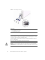
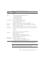
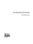
Sun Blade T6340 Server Module Field-Replaceable Units (FRUs) are shown in
FIGURE 1-4.
1-6
Sun Blade T6340 Server Module Service Manual • April 2010
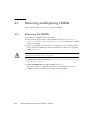
FIGURE 1-4
Field-Replaceable Units
TABLE 1-3
Sun Blade T6340 Server Module FRU List
Callout #
Description
Replacement Instructions
1
Up to two SFF SAS or SATA 2.5-inch hard drives in
mounting bracket; HDD0 and HDD1.
Section 3.1, “Hot-Plugging a
Hard Drive” on page 3-2
2
REM Battery tray
Section 4.6.3, “Installing and
Removing the Sun Blade
RAID 5 Expansion Module
Battery Tray” on page 4-23
3
Service processor. Controls the host power and monitors
host system events (power and environmental). Socketed
EEPROM stores system configuration, all Ethernet MAC
addresses, and the host ID.
Section 4.4, “Removing and
Replacing the Service
Processor” on page 4-14
Chapter 1
Sun Blade T6340 Server Module Product Description
1-7
TABLE 1-3
Sun Blade T6340 Server Module FRU List (Continued)
Callout #
Description
Replacement Instructions
4
FB-DIMMs. 1 Gbyte, 2 Gbyte, 4 Gbyte, or 8Gbyte
Section 4.3, “Removing and
Replacing DIMMs” on
page 4-10
5
FEM (pass-through)
Section 4.8, “Removing and
Replacing a Fabric
ExpressModule (FEM)” on
page 4-27
6
FEM (XAUI)
Section 4.8, “Removing and
Replacing a Fabric
ExpressModule (FEM)” on
page 4-27
7
RAID expansion module (REM).
Hard drive management for up to 8 hard drives
Section 4.6, “Replacing and
Installing the Sun Blade RAID
5 Expansion Module” on
page 4-18
8
Compact Flash memory module
Section 4.9, “Replacing the
Compact Flash Module” on
page 4-29
Server Module
Enclosure with CPU, motherboard
Replace with new server
module
1-8
Sun Blade T6340 Server Module Service Manual • April 2010
FIGURE 1-5
PCI Express and Ethernet Connections on a Sun Blade 6000 Modular System
BL = blade (server module)
NEM1
NEM0
Chapter 1
Sun Blade T6340 Server Module Product Description
1-9
1.1.1
Multicore Processor Information
The UltraSPARC® T2 Plus multicore processor is the basis of the Sun Blade T6340
server module. This server module supports two UltraSPARC T2 CPU modules.
Each processor has four, six, or eight UltraSPARC cores. Each core equates to a 64-bit
execution pipeline capable of running eight threads. The result is that the 8-core
processor handles up to 128 active threads concurrently. For more information about
the UltraSPARC® T2 Plus multicore processors, go to:
http://www.sun.com/processors/UltraSPARC-T2/features.xml
http://www.sun.com/servers/wp.jsp?tab=1
1.2
Support for RAID Storage
Configurations
By attaching one or more external storage devices to the Sun Blade T6340 server
module, you can use a redundant array of independent drives (RAID) to configure
system drive storage in a variety of different RAID levels.
As shipped, the Sun Blade T6320 Server hard drives are not configured for RAID. To
make a disk part of a RAID array while preserving the data on the drive, add the
drive to a mirrored RAID set (also known as hardware RAID Level 1).
Before configuring RAID, you must configure a RAID expansion module (REM).The
Sun Blade T6340 Server Module supports two REMs, the Sun Blade RAID 5 and Sun
Blade RAID 0/1 G2 Expansion Modules.
Refer to the following for RAID configuration instructions:
■
Uniform Command-Line Interface User's Guide, 820-2145
■
Sun StorageTek RAID Manager Software User's Guide, 820-1177
■
Sun Blade 6000 Disk Module Administration Guide, 820-4922
http://docs.sun.com/app/docs/prod/blade.6000disk~blade6000dskmod
1.2.1
Sun Blade RAID 5 Expansion Module
The Sun Blade RAID 5 Expansion Module supports RAID levels 0, 1, 1E, 10, 5, or 6
with global or dedicated hot spares.
1-10
Sun Blade T6340 Server Module Service Manual • April 2010
Note – When a Sun Blade RAID 5 Expansion Module is installed, one SAS drive
must be installed in Hard Disk Drive (HDD) Slot HDD1. The Sun Blade RAID 5
Expansion Module external battery tray must be installed in Slot HDD0 (see
Section 4.6, “Replacing and Installing the Sun Blade RAID 5 Expansion Module” on
page 4-18). To enable RAID 0, 1, 5, or 10, you must also install a Sun Blade 6000 Disk
Module, which supports up to eight SAS drives.
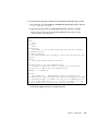
▼ To Create a Simple Volume Using Just One HDD
This task is for configurations that do not use the Sun Blade 6000 Disk Module
1. Enter the following command and options:
# ./arcconf CREATE 1 LOGICALDRIVE MAX VOLUME 0 0
Controllers found: 1
Do you want to add a logical device to the configuration?
Press y, then ENTER to continue or press ENTER to abort: y
Creating logical device: Device 0
devfsadm: mkdir failed for /dev 0x1ed: Read-only file system
Command completed successfully.
Note – You can safely ignore the mkdir failed message.
2. Perform the necessary tasks to configure the drive. Such tasks might include the
following:
■
Labeling the drive
■
Partitioning the drive
■
Preparing a file system
■
Installing data from backups or recovering data from RAID capabilities
■
Bringing the drive online
These tasks are covered in the Solaris OS administration documentation. For
additional drive verification, use SunVTS. Refer to the SunVTS and Solaris
documentation at http://docs.sun.com for details.
Chapter 1
Sun Blade T6340 Server Module Product Description
1-11
1.2.2
Sun Blade RAID 0/1 G2 Expansion Module
The Sun Blade RAID 0/1 G2 Expansion Module supports RAID 1 (two mirrored
disks with an optional hot spare) or RAID 1E (three or more mirrored disks with one
or two hot spares).
For more information, refer to the Sun Blade G2 RAID 0/1 Expansion Module
Installation Guide, 820-5448 at:
http://dlc.sun.com/pdf/820-5448-10/820-5448-10.pdf
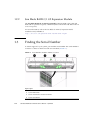
1.3
Finding the Serial Number
To obtain support for your system, you need the serial number. The serial number is
located on a sticker on the front of the server module (FIGURE 1-6).
FIGURE 1-6
Serial Number and MAC Address Locations
Figure Legend
1-12
1
Product Name: Sun Blade T6340 Server Module
2
System MAC Number
3
Chassis Serial Number and Sun Part Number
4
System Serial Number
Sun Blade T6340 Server Module Service Manual • April 2010
Chapter 1
Sun Blade T6340 Server Module Product Description
1-13
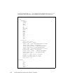
You can type the ILOM show /SYS command or the ALOM CMT showplatform
command to obtain the chassis serial number. Both examples are shown below.
-> show /SYS
/SYS
Targets:
SERVICE
LOCATE
ACT
OK2RM
SP
MB
MIDPLANE
HDD0
HDD1
NEM0
NEM1
FM0... .... .... ...
PS0
PS1
CMM
Properties:
type = Host System
keyswitch_state = Normal
chassis_name = SUN BLADE 6000 MODULAR SYSTEM
chassis_part_number = 541-1983-0
chassis_serial_number = 1005LCB-0804YM04XE
chassis_manufacturer = SUN MICROSYSTEMS
product_name = Sun Blade T6340 Server Module
product_part_number = 541-3299-02
product_serial_number = 1005LCB-08268N0008
product_manufacturer = SUN MICROSYSTEMS
fault_state = OK
prepare_to_remove_status = NotReady
prepare_to_remove_action = (none)
return_to_service_action = (none)
power_state = On
Commands:
cd
reset
set
show
start
stop
1-14
Sun Blade T6340 Server Module Service Manual • April 2010
ALOM CMT example:
sc> showplatform
SUNW, Sun Blade T6340 Server Module
Blade Serial Number: 1005LCB-08268N0008
Chassis Serial Number: 1005LCB-0804YM04XE
Slot Number: 5
Domain Status
------ -----S0
Running
sc>
1.4
Additional Service Related Information
Documentation for the Sun Blade T6340 server module, and related hardware and
software is listed in “Related Documentation” on page xiii.
The following resources are also available.
■
SunSolvesm Online – Provides a collection of support resources. Depending on
the level of your service contract, you have access to Sun patches, the Sun System
Handbook, the SunSolve knowledge base, the Sun Support Forum, and additional
documents, bulletins, and related links. Access this site at:
http://www.sunsolve.sun.com/handbook_pub/
■
Predictive Self-Healing Knowledge Database – You can access the knowledge
article corresponding to a self-healing message by taking the Sun Message
Identifier (SUNW-MSG-ID) and typing it into the field on this page:
http://www.sun.com/msg/
Chapter 1
Sun Blade T6340 Server Module Product Description
1-15
1-16
Sun Blade T6340 Server Module Service Manual • April 2010
CHAPTER
2
Diagnostics
This chapter describes the diagnostics that are available for monitoring and
troubleshooting the Sun Blade T6340 server module. This chapter is intended for
technicians, service personnel, and system administrators who service and repair
computer systems.
The following topics are covered:
2.1
■
Section 2.1, “Sun Blade T6340 Server Module Diagnostics Overview” on page 2-1
■
Section 2.2, “Memory Configuration and Fault Handling” on page 2-6
■
Section 2.3, “Interpreting System LEDs” on page 2-11
■
Section 2.4, “Using ILOM for Diagnosis and Repair Verification” on page 2-14
■
Section 2.5, “Using the ILOM Web Interface For Diagnostics” on page 2-17
■
Section 2.6, “Running POST” on page 2-27
■
Section 2.7, “Using the Solaris Predictive Self-Healing Feature” on page 2-38
■
Section 2.8, “Collecting Information From Solaris OS Files and Commands” on
page 2-44
■
Section 2.9, “Managing Components With Automatic System Recovery
Commands” on page 2-45
■
Section 2.10, “Exercising the System With SunVTS” on page 2-48
■
Section 2.11, “Resetting the Password to the Factory Default” on page 2-52
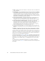
Sun Blade T6340 Server Module
Diagnostics Overview
There are a variety of diagnostic tools, commands, and indicators you can use to
monitor and troubleshoot a Sun Blade T6340 server module.
2-1
■
LEDs – Provide a quick visual notification of the status of the server module and
some of the FRUs.
■
ILOM firmware – This system firmware runs on the service processor. In addition
to providing the interface between the hardware and the Solaris OS, ILOM tracks
and reports the health of key server module components. ILOM works closely
with POST and Solaris Predictive Self-Healing technology to keep the system up
and running even when there is a faulty component. For more information about
ILOM, refer to the ILOM documentation collections.
■
Power-on self-test (POST) – POST performs diagnostics on system components
upon system reset to ensure the integrity of those components. POST is
configurable and works with ILOM to take faulty components offline if needed.
■
Solaris OS Predictive Self-Healing (PSH) – This technology continuously
monitors the health of the CPU and memory, and other components. PSH works
with ILOM to take a faulty component offline if needed. The Predictive
Self-Healing technology enables Sun systems to accurately predict component
failures and mitigate many serious problems before they occur.
■
Log files and console messages – Provide the standard Solaris OS log files and
investigative commands that can be accessed and displayed on the device of your
choice.
■
SunVTS – An application that exercises the system, provides hardware validation,
identifies possible faulty components, and provides recommendations for repair.
The LEDs, ILOM, Solaris OS PSH, and many of the log files and console messages are
integrated. For example, when the Solaris software detects a fault, it will display the
fault, log it, pass information to ILOM where the fault is logged, and depending on
the fault, one or more LEDs might be illuminated.
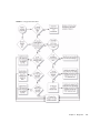
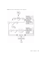
The diagnostic flowchart in FIGURE 2-1 and TABLE 2-1 describes an approach for using
the server module diagnostics to identify a faulty field-replaceable unit (FRU). The
diagnostics you use, and the order in which you use them, depend on the nature of
the problem you are troubleshooting, so you might perform some actions and not
others.
Use this flowchart to understand what diagnostics are available to troubleshoot
faulty hardware, and use TABLE 2-1 to find more information about each diagnostic in
this chapter.
2-2
Sun Blade T6340 Server Module Service Manual • April 2010
FIGURE 2-1
Diagnostic Flowchart
Chapter 2
Diagnostics
2-3
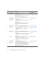
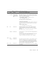
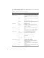
TABLE 2-1
Action
No.
Diagnostic Flowchart Actions
Diagnostic Action
Resulting Action
For more information, see
these sections
1.
Check the OK LED. The OK LED is located on the front of the Sun Blade Section 2.3, “Interpreting
T6340 server module.
System LEDs” on page 2-11
If the LED is not lit, check that the blade is properly
connected and the chassis has power.
2.
Type the ILOM
show faulty
command to check
for faults.
The faultmgmt command displays the following
types of faults:
• Environmental faults
• Solaris Predictive Self-Healing (PSH) detected
faults
• POST detected faults
Faulty FRUs are identified in fault messages using
the FRU name. For a list of FRU names, see
TABLE 1-3.
Section 2.5.1, “Displaying
System Faults” on
page 2-18
3.
Check the Solaris
log files for fault
information.
The Solaris message buffer and log files record
system events and provide information about faults.
• If system messages indicate a faulty device,
replace the FRU.
• To obtain more diagnostic information, go to
Action 4.
Section 2.8, “Collecting
Information From Solaris
OS Files and Commands”
on page 2-44
4.
Run the SunVTS
software.
SunVTS can exercise and diagnose FRUs. To run
Section 2.10, “Exercising
SunVTS, the server module must be running the
the System With SunVTS”
Solaris OS.
on page 2-48
• If SunVTS reports a faulty device replace the FRU.
• If SunVTS does not report a faulty device, go to
Action 5.
5.
Run POST.
POST performs basic tests of the server module
components and reports faulty FRUs.
• If POST indicates a faulty FRU, replace the FRU.
• If POST does not indicate a faulty FRU, go to
Action 9.
Section 2.6, “Running
POST” on page 2-27
6.
Determine if the
fault is an
environmental
fault.
If the fault listed by the show faulty
command displays a temperature or voltage fault,
then the fault is an environmental fault.
Environmental faults can be caused by faulty FRUs
(chassis power supply, fan, or blower) or by
environmental conditions such as high ambient
temperature, or blocked airflow.
Section 2.5.1, “Displaying
System Faults” on
page 2-18
2-4
Sun Blade T6340 Server Module Service Manual • April 2010
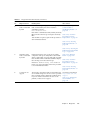
TABLE 2-1
Action
No.
7.
Diagnostic Flowchart Actions (Continued)
Diagnostic Action
Resulting Action
Determine if the
fault was detected
by PSH.
If the fault message displays the following text, the
fault was detected by the Solaris Predictive
Self-Healing software:
Host detected fault
If the fault is a PSH detected fault, identify the faulty
FRU from the fault message and replace the faulty
FRU.
After the FRU is replaced, perform the procedure to
clear PSH detected faults.
For more information, see
these sections
Section 2.7, “Using the
Solaris Predictive
Self-Healing Feature” on
page 2-38
Section 4.2, “Common
Procedures for Parts
Replacement” on page 4-3
Section 2.7.2, “Clearing
PSH Detected Faults” on
page 2-42
Section 2.7.3, “Clearing the
PSH Fault From the ILOM
Logs” on page 2-43
8.
Determine if the
fault was detected
by POST.
POST performs basic tests of the server module
components and reports faulty FRUs. When POST
detects a faulty FRU, it logs the fault and if possible
takes the FRU offline. POST detected FRUs display
the following text in the fault message:
FRU-name deemed faulty and disabled
In this case, replace the FRU and run the procedure
to clear POST detected faults.
9.
Contact Sun for
support.
The majority of hardware faults are detected by the
server module diagnostics. In rare cases it is possible
that a problem requires additional troubleshooting.
If you are unable to determine the cause of the
problem, contact Sun for support.
Section 2.6, “Running
POST” on page 2-27
Section 4.2, “Common
Procedures for Parts
Replacement” on page 4-3
Section 2.6.4, “Clearing
POST Detected Faults” on
page 2-35
Sun Support information:
http://www.sun.com/
support
Section 1.3, “Finding the
Serial Number” on
page 1-12
Chapter 2
Diagnostics
2-5
2.2
Memory Configuration and Fault
Handling
This section describes how the memory is configured and how the server module
deals with memory faults.
2.2.1
Memory Configuration
The Sun Blade T6340 server module has 32 connectors (slots) that hold fully-buffered
DIMMs (FB-DIMMs) in the following FB-DIMM capacities:
■
1 Gbyte (maximum of 32 Gbytes)
■
2 Gbyte (maximum of 64 Gbytes)
■
4 Gbyte (maximum of 128 Gbytes)
■
8 Gbyte (maximum of 256 Gbytes)
The Sun Blade T6340 server module performs best if all 32 connectors are populated
with 32 identical DIMMs. This configuration also enables the system to continue
operating even when a DIMM fails, or if an entire channel fails.
Note – All installed FB-DIMMs will be seen by the system as having the capacity of
the smallest installed FB-DIMM.
For example, suppose that you have installed 32 8-Gbyte FB-DIMMs for a total of 256
Gbytes of memory. If you were to replace one of those 8-Gbyte FB-DIMMs with a
functioning 1-Gbyte FB-DIMM, the system will now treat all installed FB-DIMMs as
1 Gbyte FB-DIMMs and thus see only 32 Gbytes of installed memory, .
2-6
Sun Blade T6340 Server Module Service Manual • April 2010
2.2.1.1
FB-DIMM Installation Rules
Caution – The following FB-DIMM rules must be followed. The server module
might not operate correctly if the FB-DIMM rules are not followed. Always use
FB-DIMMs that have been qualified by Sun.
Use these FB-DIMM configuration rules to help you plan the memory configuration
of your server:
■
32 slots hold industry-standard FB-DIMM memory modules on the motherboard.
■
All FB-DIMMs must have the same Sun part number. The system treats all
installed FB-DIMMs as the lowest-capacity installed FB-DIMM.
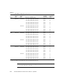
■
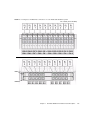
Install FB-DIMMs in this order, refer to FIGURE 2-2:
■
Fill FB-DIMMs of group 8 first.
■
Fill FB-DIMMs of group 16 next.
■
Fill FB-DIMMs of group 24 next.
■
Fill FB-DIMMs of group 32 last.
See Section 4.3.1, “Removing the DIMMs” on page 4-10 for DIMM installation
instructions.
Chapter 2
Diagnostics
2-7
FIGURE 2-2
DIMM Installation Rules
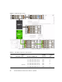
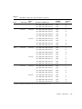
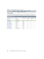
You can also use TABLE 2-2 to identify the DIMMs you want to remove.
TABLE 2-2
FB-DIMM Configuration and Installation
CPU #
Branch Name
Channel
Name
CMP 0
Branch 0
Channel 0
Channel 1
2-8
FRU Name in ILOM Messages
Motherboard
FB-DIMM
Connector
FB-DIMM
Installation
Order*
/SYS/MB/CMP0/BR0/CH0/D0
J0501
8
/SYS/MB/CMP0/BR0/CH0/D1
J0601
16
/SYS/MB/CMP0/BR0/CH0/D2
J0701
24
/SYS/MB/CMP0/BR0/CH0/D3
J0801
24
/SYS/MB/CMP0/BR0/CH1/D0
J0901
8
/SYS/MB/CMP0/BR0/CH1/D1
J1001
16
Sun Blade T6340 Server Module Service Manual • April 2010
TABLE 2-2
CPU #
FB-DIMM Configuration and Installation (Continued)
Branch Name
Branch 1
Channel
Name
Channel 0
Channel 1
CMP 1
Branch 0
Channel 0
Channel 1
Branch 1
Channel 0
Channel 1
FRU Name in ILOM Messages
Motherboard
FB-DIMM
Connector
FB-DIMM
Installation
Order*
/SYS/MB/CMP0/BR0/CH1/D2
J1101
24
/SYS/MB/CMP0/BR0/CH1/D3
J1201
24
/SYS/MB/CMP0/BR1/CH0/D0
J1301
8
/SYS/MB/CMP0/BR1/CH0/D1
J1401
16
/SYS/MB/CMP0/BR1/CH0/D2
J1501
24
/SYS/MB/CMP0/BR1/CH0/D3
J1601
24
/SYS/MB/CMP0/BR1/CH1/D0
J1701
8
/SYS/MB/CMP0/BR1/CH1/D1
J1801
16
/SYS/MB/CMP0/BR1/CH1/D2
J1901
24
/SYS/MB/CMP0/BR1/CH1/D3
J2001
24
/SYS/MB/CMP1/BR0/CH0/D0
J2401
8
/SYS/MB/CMP1/BR0/CH0/D1
J2501
16
/SYS/MB/CMP1/BR0/CH0/D2
J2601
32
/SYS/MB/CMP1/BR0/CH0/D3
J2701
32
/SYS/MB/CMP1/BR0/CH1/D0
J2801
8
/SYS/MB/CMP1/BR0/CH1/D1
J2901
16
/SYS/MB/CMP1/BR0/CH1/D2
J2601
32
/SYS/MB/CMP1/BR0/CH1/D3
J2701
32
/SYS/MB/CMP1/BR1/CH0/D0
J3201
8
/SYS/MB/CMP1/BR1/CH0/D1
J3301
16
/SYS/MB/CMP1/BR1/CH0/D2
J3401
32
/SYS/MB/CMP1/BR1/CH0/D3
J3501
32
/SYS/MB/CMP1/BR1/CH1/D0
J3601
8
/SYS/MB/CMP1/BR1/CH1/D1
J3701
16
/SYS/MB/CMP1/BR1/CH1/D2
J3801
32
/SYS/MB/CMP1/BR1/CH1/D3
J3901
32
* Upgrade path: DIMMs should be added with each group populated in the order shown.
Chapter 2
Diagnostics
2-9
2.2.1.2
Memory Fault Handling
The Sun Blade T6340 server module uses advanced ECC technology, also called chipkill,
that corrects up to 4-bits in error on nibble boundaries, as long as they are all in the same
DRAM. If a DRAM fails, the DIMM continues to function.
Note – The chipkill function is only supported on DIMMs that use “x4” DRAMs.
The following server module features manage memory faults independently.
■
POST – Runs when the server module is powered on (based on configuration
variables) and thoroughly tests the memory subsystem.
If a memory fault is detected, POST displays the fault with the FRU name of the
faulty DIMMs, logs the fault, and disables the faulty DIMMs by placing them in
the Automatic System Recovery (ASR) blacklist. For a given memory fault, POST
disables half of the physical memory in the system. When this occurs, you must
replace the faulty DIMMs based on the fault message and enable the disabled
DIMMs with the ILOM command set /SYS/component component_state=
enabled .
■
2.2.1.3
Solaris Predictive Self-healing (PSH) technology – A feature of the Solaris OS,
uses the fault manager daemon (fmd) to watch for various kinds of faults. When
a fault occurs, the fault is assigned a unique fault ID (UUID), and logged. PSH
reports the fault and provides a recommended proactive replacement for the
DIMMs associated with the fault.
Troubleshooting Memory Faults
If you suspect that the server module has a memory problem, follow the flowchart
(FIGURE 2-1). Type the ILOM command: show faulty . The faultmgmt command
lists memory faults and lists the specific DIMMs that are associated with the fault.
Once you have identified which DIMMs to replace, see Chapter 4 for DIMM removal
and replacement instructions. You must perform the instructions in that chapter to
clear the faults and enable the replaced DIMMs.
2-10
Sun Blade T6340 Server Module Service Manual • April 2010
2.3
Interpreting System LEDs
The Sun Blade T6340 server module has LEDs on the front panel and the hard drives.
The behavior of LEDs on your server module conforms to the American National
Standards Institute (ANSI) Status Indicator Standard (SIS). These standard LED
behaviors are described in TABLE 2-3.
2.3.1
Front Panel LEDs and Buttons
The front panel LEDs and buttons are located in the center of the server module
(TABLE 2-4, and TABLE 2-5). The functions of their respective devices are displayed as
follows:
TABLE 2-3
LED Behavior and Meaning
LED Behavior
Meaning
Off
The condition represented by the color is not true.
Steady on
The condition represented by the color is true.
Standby blink
The system is functioning at a minimal level and ready to resume full function.
Slow blink
Transitory activity or new activity represented by the color that is taking place.
Fast blink
Attention is required.
Feedback flash
Activity is taking place commensurate with the flash rate (such as disk drive activity).
The front panel LEDs on the Sun Blade T6340 are shown in FIGURE 2-3:
Chapter 2
Diagnostics
2-11
FIGURE 2-3
Front Panel and Hard Drive LEDs
Figure Legend
1
White Locator LED
7
Universal Connector Port (UCP)
2
Blue Ready to Remove LED
8
Green Drive OK LED
3
Amber Service Action Required LED
9
Amber Drive Service Action Required LED
4
Green OK LED
10
Blue Drive Ready to Remove LED
5
Power Button
11
Chassis power connector
6
Reset Button (for service use only)
12
Chassis data connector
2-12
Sun Blade T6340 Server Module Service Manual • April 2010
TABLE 2-4
LED Behaviors With Assigned Meanings
Color
Behavior
Definition
White
Off
Steady state
Fast blink
4 Hz repeating
sequence, equal
intervals On and
Off.
Description, Actions, and ILOM Commands
This indicator helps you to locate a particular enclosure, board, or
subsystem (for example, the Locator LED). The LED is activated
using one of the following methods:
• Press the button to toggle the indicator on or off, or
type the ILOM command:
set /SYS/LOCATE value=Off
This LED provides the following indications:
• Off– Normal operating state.
Fast blink – The server module received a signal as a result of one
of the preceding methods and indicats that the server module is
active.
• Type the ILOM command:
set /SYS/LOCATE value=Fast_Blink
Blue
Amber
Green
Off
Steady state
Steady state - If LED is off, it is not safe to remove the server
module from the chassis. You must use software to take the
component offline or shut down the server. To turn off the blue
LED, type:
set /SYS return_to_service_action=true
Steady on
Steady state
If the blue LED is on, a service action can be safely performed on
the component.
To remove a server module (and illuminate the blue LED), type:
set /SYS prepare_to_remove_action=true
To remove a hard drive, use the Solaris cfgadm command
Off
Steady state
Steady on
Steady state
This indicator signals the existence of a fault condition. Service is
required (for example, the Service Required LED). The ILOM
show faulty command provides details about any faults that
cause this indicator to be lit. To turn off an amber LED, either fix
the fault condition or mark the fault condition fixed.
Off
Steady state
Off – The system is unavailable. Either it has no power or ILOM is
not running.
Chapter 2
Diagnostics
2-13
TABLE 2-4
Color
LED Behaviors With Assigned Meanings (Continued)
Behavior
Definition
Description, Actions, and ILOM Commands
Standby
blink
Repeating sequence
consisting of a brief
(0.1 sec.) on flash
followed by a long
off period (2.9 sec.)
The system is running at a minimum level and is ready to be
quickly revived to full function (for example, the System Activity
LED).
Steady on
Steady state
Status normal; system or component functioning with no service
actions required.
Slow blink
2.3.2
A transitory (temporary) event is taking place for which direct
proportional feedback is not needed or not feasible.
ILOM is enabled but the server module is not fully powered on.
Indicates that the service processor is running while the system is
running at a minimum level in standby mode and ready to be
returned to its normal operating state.
Power and Reset Buttons
TABLE 2-5
Button
Front Panel Buttons
Color
Description
Power button gray
Turns the host system on and off. Use a non-conductive stylus to
completely press this button.
(reset)
This button causes a reset of the Service Processor.
gray
For information about Ethernet LEDs see the service manual for your modular
system chassis or ethernet device at:
http://docs.sun.com/app/docs/prod/blade.6000mod
2.4
Using ILOM for Diagnosis and Repair
Verification
The Oracle Integrated Lights Out Manager (ILOM) is contained on firmware on the
service processor in the Sun Blade T6340 server module. ILOM enables you to
remotely manage and administer your server module.
2-14
Sun Blade T6340 Server Module Service Manual • April 2010
Note – ILOM also contains an ALOM-CMT compatibility shell. For more
information about ALOM-CMT compatibility see the Sun Integrated Lights Out
Manager 2.0 Supplement for Sun Blade T6340 Server Modules, 820-3904. Appendix G of
this service manual also provides some information about the ALOM CMT CLI.
ILOM enables you to run remote diagnostics such as power-on self-test (POST), that
would otherwise require physical proximity to the server module serial port. You can
also configure ILOM to send email alerts of hardware failures, hardware warnings,
and other events related to the server module or to ILOM.
The ILOM circuitry runs independently of the server module, using the server
module standby power. Therefore, ILOM firmware and software continue to function
when the server module operating system goes offline or when the server module is
powered off.
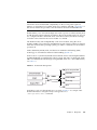
Faults detected by ILOM, POST, and the Solaris Predictive Self-healing (PSH)
technology are forwarded to ILOM for fault handling (FIGURE 2-4).
In the event of a system fault, ILOM ensures that the Service Action Required LED is
lit, FRU ID PROMs are updated, the fault is logged, and alerts are displayed (faulty
FRUs are identified in fault messages using the FRU name. For a list of FRU names,
see TABLE 1-3).
FIGURE 2-4
ILOM Fault Management
Service Required LED
FRU LEDs
ILOM
FRUID PROMs
Event Logs
Alerts
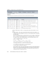
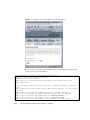
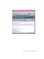
In ILOM you can view the ILOM logs to see alerts. FIGURE 2-5 is a sample of the
ILOM web interface. Using the CLI you can type the show
/SP/logs/event/list/ command.
Chapter 2
Diagnostics
2-15
FIGURE 2-5
Sample Event Log in ILOM Web Interface
ILOM can detect when a fault is no longer present and clears the fault in several
ways:
■
Fault recovery – The system automatically detects that the fault condition is no
longer present. ILOM extinguishes the Service Action Required LED and updates
the FRU PROM.
Many environmental faults can automatically recover. For example, a temperature
that is exceeding a threshold might return to normal limits when you connect a
fan. The recovery of environmental faults is automatically detected. Recovery
events are reported using one of two forms:
■
fru at location is OK.
■
sensor at location is within normal range.
There are three thresholds for an environmental fault:
■
Warning: ILOM issues a command to burst the fan speed.
■
Soft shutdown: ILOM initiates a graceful shutdown.
■
Hard shutdown: Immediate shutdown.
Environmental faults can be repaired through hot removal of the faulty FRU. The
FRU removal is automatically detected by the environmental monitoring and all
faults associated with the removed FRU are cleared. The message for that case,
and the alert sent for all FRU removals is:
2-16
Sun Blade T6340 Server Module Service Manual • April 2010
fru at location has been removed.
■
2.5
Fault repair – The fault has been repaired by human intervention. In most cases,
ILOM detects the repair and extinguishes the Service Required LED. In the event
that ILOM does not perform these actions, you must perform these tasks manually
with the following commands:
■
set /SYS/FRU/clear_fault_action=true (The ALOM-CMT equivalent
is clearfault) clears the PSH fault logs but does not enable the component.
See Section 2.7.2, “Clearing PSH Detected Faults” on page 2-42.
■
set /SYS/component/component_state=enabled (The ALOM-CMT
equivalent is enablecomponent) clears POST generated faults and enables the
component. See Section 2.6.4, “Clearing POST Detected Faults” on page 2-35.
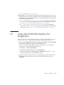
Using the ILOM Web Interface For
Diagnostics
These instructions use the ILOM web interface. To use the command line interface
(CLI), see Appendix G of this manual, the ILOM documentation collection.
1. Connect to the ILOM web interface by typing the IP address for the Sun Blade
T6340 server module service processor in a web browser.
If you do not know the IP address for the server module, you can obtain the
service processor IP address from the following:
■
ILOM CLI: ->show /SP/network
■
ALOM-CMT compatibility shell: sc> shownetwork
■
Chassis CMM ILOM: ->show /CH/BL<x>/SP/network (Where <x> is the
number of the blade server module in the chassis.)
2. Type the username and password to access the diagnostics menus in the ILOM
web interface. The default user name is root, and the default password is
changeme.
Chapter 2
Diagnostics
2-17
FIGURE 2-6
2.5.1
ILOM Login Screen
Displaying System Faults
ILOM displays the following faults with the web interface and CLI:
■
Environmental faults – Temperature or voltage problems that might be caused by
faulty FRUs (power supplies, fans, or blower), or by room temperature or blocked
air flow
■
POST detected faults – Detected by the power-on self-test diagnostics
■
PSH detected faults – Detected by the Solaris Predictive Self-healing (PSH)
technology
Use the web interface or type the show faulty command for the following
reasons:
2-18
■
To see if any faults have been passed to, or detected by the ILOM firmware
■
To obtain the fault message ID (SUNW-MSG-ID) for PSH detected faults
■
To verify that the replacement of a FRU has cleared the fault and not generated
any additional faults
Sun Blade T6340 Server Module Service Manual • April 2010
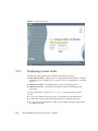
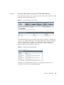
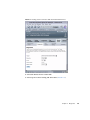
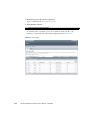
2.5.1.1
Viewing Fault Status Using the ILOM Web Interface
In the ILOM web interface, you can view the system components currently in a fault
state using the Fault Management page.
FIGURE 2-7
Fault Management Page Example
The Fault Management page lists faulted components by ID, FRU, and TimeStamp.
You can access additional information about the faulted component by clicking the
faulted component ID. For example, if you clicked the faulted component ID, 0
SYS/MB/, a dialog window similar to the following one appears, displaying
additional details about the faulted component.
FIGURE 2-8
Faulted Component ID Window
Alternatively, in the ILOM web interface, you can identify the fault status of a
component on the Component Management page.
Chapter 2
Diagnostics
2-19
FIGURE 2-9
2-20
Component Management Page - Fault Status
Sun Blade T6340 Server Module Service Manual • April 2010
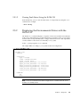
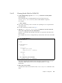
2.5.1.2
Viewing Fault Status Using the ILOM CLI
In the ILOM CLI, you can view the fault status of component(s) by using the show
command. For example:
->show faulty
2.5.2
Displaying the Environmental Status with the
ILOM CLI
The ILOM show command displays a snapshot of the server module environmental
status. This command displays system temperatures, hard drive status, power supply
and fan status, front panel LED status, voltage, and current sensors. The output uses
a format similar to the Solaris OS command prtdiag (1M).
At the -> prompt, type the show command.
The output differs according to your system model and configuration.
-> show /SYS/MB/V_+12V
/SYS/MB/V_+12V
Targets:
Properties:
type = Voltage
class = Threshold Sensor
value = 12.411 Volts
upper_nonrecov_threshold = 13.23 Volts
upper_critical_threshold = 13.10 Volts
upper_noncritical_threshold = 12.85 Volts
lower_noncritical_threshold = 11.15 Volts
lower_critical_threshold = 10.90 Volts
lower_nonrecov_threshold = 10.77 Volts
Commands:
cd
show
Note – Some environmental information might not be available when the server
module is in standby mode.
Chapter 2
Diagnostics
2-21
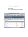
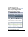
2.5.3
Displaying the Environmental Status and Sensor
Readings with the ILOM Web Interface
1. Open a web browser and type the IP address of the server module service
processor in the browser.
2. Select the top System Monitoring tab and the lower Sensor Readings tab
(FIGURE 2-10).
3. Click on the sensor reading that you want to check (FIGURE 2-10).
FIGURE 2-10
2-22
Obtaining Sensor Readings and Environmental Status With the ILOM Web Interface
Sun Blade T6340 Server Module Service Manual • April 2010
FIGURE 2-11
2.5.4
Sensor Reading Window for an FB-DIMM in Channel 1
Displaying FRU Information
ILOM can display static FRU information such as the FRU manufacturer, serial
number and some FRU status information (FIGURE 2-12).
Note – To view dynamic FRU information you must type the ALOM CMT showfru
command. The dynamic FRU information provides more details about FRUs.
2.5.4.1
Using the ILOM Web Interface to Display FRU Information
1. Select the System Information and Components tabs.
2. Click on the component to view the FRU information (FIGURE 2-12).
Chapter 2
Diagnostics
2-23
FIGURE 2-12
2.5.4.2
Static FRU Information in the ILOM Web Interface
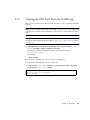
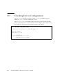
Using the CLI to Display FRU Information
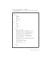
The show /SYS/MB command displays static information about the FRUs in the
server module. Use this command to see information about an individual FRU.
2-24
Sun Blade T6340 Server Module Service Manual • April 2010
●
At the -> prompt, type the show command.
In the following example, the show command displays information about the
motherboard (MB).
-> show /SYS/MB
/SYS/MB
Targets:
SEEPROM
SCC_NVRAM
PCIE0
PCIE1
PCI-SWITCH0
PCI-SWITCH1
REM
NET0
CMP0
CMP1
V_VDDIO
V_+12V
V_+3V3
V_+3V3_STBY
V_+5V
Properties:
type = Motherboard
chassis_name = SUN BLADE 6000 MODULAR SYSTEM
chassis_part_number = "541-1983-0
chassis_serial_number = "1005LCB-0804YM04XE
chassis_manufacturer = SUN MICROSYSTEMS
product_name = Sun Blade T6340 Server Module
product_part_number = 541-3299-02
product_serial_number = 1005LCB-08268N0008
product_manufacturer = SUN MICROSYSTEMS
fru_name = T6340_MB
fru_description = 8C,1.2GHZ VF,T6340,DIRECT-A
fru_manufacturer = NO JEDEC CODE FOR THIS VENDOR
fru_version = 02_01
fru_part_number = 5407762
fru_serial_number = 8J0010
fault_state = OK
clear_fault_action = (none)
Commands:
cd
show
->
Chapter 2
Diagnostics
2-25
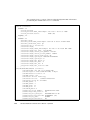
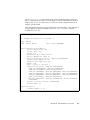
This example shows a portion of the more detailed dynamic FRU information
provided by the ALOM CMT showfru command.
sc> showfru
/SYS/SP (container)
SEGMENT: ST
/Status_CurrentR
/Status_CurrentR/UNIX_Timestamp32: Thu Feb 17 07:25:57 2000
/Status_CurrentR/status:
0x00 (OK)
SEGMENT: TH ...
... ... ...
SEGMENT: FD
/Customer_DataR
/Customer_DataR/UNIX_Timestamp32: Wed Feb 16 08:41:44 GMT 2000
/Customer_DataR/Cust_Data: QT
/InstallationR (1 iterations)
/InstallationR[0]
/InstallationR[0]/UNIX_Timestamp32: Thu Feb 17 07:26:09 GMT 2000
/InstallationR[0]/Fru_Path: /SYS/MB/REM
/InstallationR[0]/Parent_Part_Number: 5017821
/InstallationR[0]/Parent_Serial_Number: 5C00FV
/InstallationR[0]/Parent_Dash_Level: 04
/InstallationR[0]/System_Id: 1005LCB-0709YM00FV
/InstallationR[0]/System_Tz: 0
/InstallationR[0]/Geo_North: 0
/InstallationR[0]/Geo_East: 0
/InstallationR[0]/Geo_Alt: 0
/InstallationR[0]/Geo_Location: GMT
... ... ...
/SYS/MB/CMP0/BR0/CH0/D0 (container)
/SPD/Timestamp: Mon Feb 12 12:00:00 2007
/SPD/Description: DDR2 SDRAM FB-DIMM, 4 GByte
/SPD/Manufacture Location: ff
/SPD/AMB Vendor: IDT
/SPD/Vendor: Micron Technology
/SPD/Vendor Part No:
36HTF51272F667E1D4
/SPD/Vendor Serial No: d2174043
/SPD/Num_Banks: 8
/SPD/Num_Ranks: 2
/SPD/Num_Rows: 14
/SPD/Num_Cols: 11
/SPD/Sdram_Width: 4
/SunSPD/Sun_Serial_Number:
002C010707D2174043
/SunSPD/SPD_Format_Version: 20
/SunSPD/Sun_Part_Dash_Rev:
000-0000-00 Rev 00
/SunSPD/Certified_Platforms: 0x00000001 (OK)
/SunSPD/Sun_Key_Code:
0x0000
/SunSPD/Sun_Certification:
NO
2-26
Sun Blade T6340 Server Module Service Manual • April 2010
/SunSPD/timestamp:
/SunSPD/MACADDR:
/SunSPD/status
/SunSPD/Initiator
/SunSPD/Message:
/SunSPD/powerupdate:
/SunSPD/Poweron_minutes:
/SYS/MB/CMP0/BR1/CH0/D0 (container)
... ... ...
sc>
2.6
Thu Feb 17 07:26:20 2000
00:14:4F:98:84:7A
0x00 (OK)
N/A
No message
Thu Feb 17 07:01:16 2000
1487
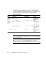
Running POST
Use POST to test and verify server module hardware. Power-on self-test (POST) is a
group of PROM-based tests that run when the server module is powered on or reset.
POST checks the basic integrity of the critical hardware components in the server
module (CPU, memory, and I/O buses).
If POST detects a faulty component, the component is disabled automatically,
preventing faulty hardware from potentially harming any software. If the system is
capable of running without the disabled component, the system will boot when
POST is complete. For example, if one of the processor cores is deemed faulty by
POST, that core will be disabled, and the system will boot and run using the
remaining cores.
You can use POST as an initial diagnostic tool for the system hardware. In this case,
configure POST to run in diagnostic service mode for maximum test coverage and
verbose output.
Note – Devices can be manually enabled or disabled using ASR commands (see
Section 2.9, “Managing Components With Automatic System Recovery Commands”
on page 2-45).
2.6.1
Controlling How POST Runs
The server module can be configured for normal, extensive, or no POST execution.
You can also control the level of tests that run, the amount of POST output that is
displayed, and which reset events trigger POST by using diag variables.
Chapter 2
Diagnostics
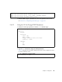
2-27
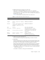
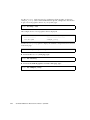
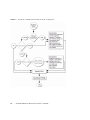
TABLE 2-6 lists the DIAG variables used to configure POST and FIGURE 2-13 shows how
the variables work together.
TABLE 2-6
Parameters Used For POST Configuration
Parameter
Values
/SYS
normal
keyswitch_state
diag_mode
diag_level
diag_trigger
diag_verbosity
2-28
Description
The system can power on and run POST (based
on the other parameter settings). For details see
FIGURE 2-13. This parameter overrides all other
commands.
diag
The system runs POST based on predetermined
settings.
stby
The system cannot power on.
locked
The system can power on and run POST, but no
flash updates can be made.
off
POST does not run.
normal
Runs POST according to diag_level value.
service
Runs POST with preset values for diag_level
and diag_verbosity.
min
If diag_mode = normal, runs minimum set of
tests.
max
If diag_mode = normal, runs all the minimum
tests plus extensive CPU and memory tests.
none
Does not run POST on reset or poweron.
user-reset
Runs POST upon user-initiated resets.
power-on-reset
Only runs POST for the first power on.
Default state is ‘power-on-reset
error-reset’
error-reset
Runs POST if fatal errors are detected.
all-resets
Runs POST after any reset.
none
No POST output is displayed.
min
POST output displays functional tests with a
banner and pinwheel.
normal
POST output displays all test and informational
messages.
max
POST displays all test, informational, and some
debugging messages.
Sun Blade T6340 Server Module Service Manual • April 2010
FIGURE 2-13
Flowchart of ILOM Variables for POST Configuration
Chapter 2
Diagnostics
2-29
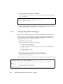
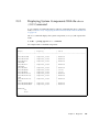
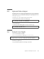
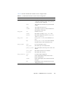
TABLE 2-7 shows typical combinations of ILOM variables and associated POST modes.
POST Modes and Parameter Settings
TABLE 2-7
Parameter
Normal Diagnostic Mode
(default settings)
No POST Execution
Diagnostic Service
Mode
Keyswitch Diagnostic
Preset Values
diag_mode
normal
off
service
normal
keyswitch_state*
normal
normal
normal
diag
diag_level
min
n/a
max
max
diag_trigger
power-on-reset
error-reset
none
all-resets
all-resets
diag_verbosity
normal
n/a
max
max
Description of POST
execution
This is the default POST
configuration. This
configuration tests the
system thoroughly, and
suppresses some of the
detailed POST output.
POST does not
run, resulting in
quick system
initialization, but
this is not a
suggested
configuration.
POST runs the full
spectrum of tests
with the maximum
output displayed.
POST runs the full
spectrum of tests
with the maximum
output displayed.
* The keyswitch_state parameter, when set to diag, overrides all the other POST variables.
2.6.2
Changing POST Parameters
You can use the web interface or the CLI to change the POST parameters.
2.6.2.1
Using the Web Interface to Change POST Parameters
1. From the ILOM web interface, select the Remote Console tab (FIGURE 2-14).
2. Select the Diagnostics Tab.
3. Select the POST settings that you require.
TABLE 2-7 describes how the POST settings will execute.
4. Click the Save button.
Note – If you do not have a console window open, you should open one. POST will
only display output to a console window, not the web interface.
2-30
Sun Blade T6340 Server Module Service Manual • April 2010
FIGURE 2-14
Setting POST Parameters With the ILOM Web Interface
5. Select the Remote Power Control Tab.
6. Select a power control setting and Select Save (FIGURE 2-15).
Chapter 2
Diagnostics
2-31
FIGURE 2-15
Changing Power Settings With the ILOM Web Interface
When you power cycle the server module, POST runs and displays output to the
service processor console window:
{0} ok Chassis | critical: Host has been powered off
Chassis | major: Host has been powered on
2007-11-07 18:22:19.511 0:0:0>
2007-11-07 18:22:19.560 0:0:0>Sun Blade T6320 Server Module POST 4.27.4
2007/10/02 19:09
/export/delivery/delivery/4.27/4.27.4/post4.27.x/Niagara/glendale/integrated
(root)
2007-11-07 18:22:19.836 0:0:0>Copyright 2007 Sun Microsystems, Inc. All rights
reserved
2007-11-07 18:22:20.001 0:0:0>VBSC cmp 0 arg is: 00ffffff.ffff00ff
2007-11-07 18:22:20.108 0:0:0>POST enabling threads: 00ffffff.ffff00ff
2007-11-07 18:22:20.223 0:0:0>VBSC mode is: 00000000.00000001
2007-11-07 18:22:20.321 0:0:0>VBSC level is: 00000000.00000001
2007-11-07 18:22:20.421 0:0:0>VBSC selecting Normal mode, MAX Testing.
2-32
Sun Blade T6340 Server Module Service Manual • April 2010
2007-11-07
2007-11-07
2007-11-07
2007-11-07
18:22:20.533
18:22:20.629
18:22:20.714
18:22:20.843
0:0:0>VBSC setting verbosity level 3
0:0:0> Niagara2, Version 2.1
0:0:0> Serial Number: 0f880060.768660a8
0:0:0>Basic Memory Tests.....
7. Read the POST output to determine if you need to perform service actions.
See Section 2.6.3, “Interpreting POST Messages” on page 2-34.
2.6.2.2
Using the CLI to Change POST Parameters
1. Verify the current post parameters with the show command. Type:
-> show /HOST/diag
/HOST/diag
Targets:
Properties:
level = min
mode = normal
trigger = power-on-reset error-reset
verbosity = normal
Commands:
cd
set
show
->
2. Type the set command to change the POST parameters.
TABLE 2-7 describes how the POST settings will execute. This example shows how
to set the verbosity to max.
-> set /HOST/diag verbosity=max
Set ’verbosity’ to ’max’
->
Chapter 2
Diagnostics
2-33
3. Power cycle the server module to run POST.
There are several ways to initiate a reset. The following example uses the ILOM
reset command.
-> reset /SYS
Are you sure you want to reset /SYS (y/n)? y
Performing hard reset on /SYS
->
4. Read the POST output to determine if you need to perform service actions. See
Section 2.6.3, “Interpreting POST Messages” on page 2-34.
2.6.3
Interpreting POST Messages
When POST is finished running and no faults were detected, the system will boot.
If POST detects a faulty device, the fault is displayed and the fault information is
passed to ILOM for fault handling. Faulty FRUs are identified in fault messages
using the FRU name. For a list of FRU names, see TABLE 1-3.
1. Interpret the POST messages:
POST error messages use the following syntax:
c:s > ERROR: TEST = failing-test
c:s > H/W under test = FRU
c:s > Repair Instructions: Replace items in order listed by H/W
under test above
c:s > MSG = test-error-message
c:s > END_ERROR
In this syntax, c = the core number, s = the strand number.
Warning and informational messages use the following syntax:
INFO or WARNING: message
The following example shows a POST error message report for a missing PCI device:
0:0:0>ERROR: TEST = PIU PCI id test
0:0:0>H/W under test = MB/PCI-SWITCH
0:0:0>Repair Instructions: Replace items in order listed by ‘H/W under test’
above.
0:0:0>MSG = PCI ID test device missing Cont.
DEVICE NAME: MB/PCI-SWITCH
0:0:0>END_ERROR
2-34
Sun Blade T6340 Server Module Service Manual • April 2010
2. Type the show faulty command to obtain additional fault information.
The fault is captured by ILOM, where the fault is logged. The Service Action
Required LED is lit, and the faulty component is disabled.
For example:
ok #.
->
-> show faulty
Target
| Property
| Value
--------------------+------------------------+---------------------------/SP/faultmgmt/0
| fru
| /SYS/MB/CMP0/BR0/CH0/D0
/SP/faultmgmt/0
| timestamp
| Sep 12 05:02:52
/SP/faultmgmt/0/
| timestamp
| Sep 12 05:02:52
faults/0
|
|
/SP/faultmgmt/0/
| sp_detected_fault
| /SYS/MB/CMP0/BR0/CH0/D0
faults/0
|
| Disabled by user
Commands:
cd
show
In this example, /SYS/MB/CMP0/BR0/CH0/D0 is disabled by a user. The system
can boot using memory that was not disabled until the faulty component is
replaced.
Note – You can use ASR commands to display and control disabled components. See
Section 2.9, “Managing Components With Automatic System Recovery Commands”
on page 2-45.
2.6.4
Clearing POST Detected Faults
In most cases, when POST detects a faulty component, POST logs the fault and
automatically takes the failed component out of operation by placing the component
in the ASR blacklist.
See Section 2.9, “Managing Components With Automatic System Recovery
Commands” on page 2-45).
After the faulty FRU is replaced, the fault is normally automatically cleared. In some
cases it might be necessary to manually clear the fault by removing the component
from the ASR blacklist.
Chapter 2
Diagnostics
2-35
2.6.4.1
Clearing Faults With the Web Interface
This procedure describes how to enable components after a POST fault has been
generated. The POST fault log is not actually cleared.
1. Select the tabs: System Information and Components tabs (FIGURE 2-16).
2. Select the radio button for the component that you must clear.
3. In the Actions menu, select: Enable Component.
FIGURE 2-16
Enabling Components With the ILOM Web Interface
Note – The Clear Faults command in the Action menu will only clear the
PSH-generated faults, and will not enable a component.
2-36
Sun Blade T6340 Server Module Service Manual • April 2010
2.6.4.2
Clearing Faults With the ILOM CLI
1. At the ILOM prompt, type the show faulty command to identify POST
detected faults.
POST detected faults are distinguished from other faults by the text:
deemed faulty and disabled, and no UUID number is reported.
For example:
-> show faulty
■
If no fault is reported, you do not need to do anything else. Do not perform the
subsequent steps.
■
If a fault is detected, continue with Step 2.
2. Type the set component_state=enabled command to clear the fault and
remove the component from the ASR blacklist.
Type the cd command with the FRU name that was reported in the fault in the
previous step.
This example shows how to change directory to thread P32 on the CPU and enable
it.
-> cd /SYS/MB/CMP0/P32
/SYS/MB/CMP0/P32
-> show
/SYS/MB/CMP0/P32
Targets:
Properties:
type = CPU thread
component_state = Disabled
Commands:
cd
show
-> set component_state=enabled
Set ’component_state’ to ’enabled’
The fault is cleared and should not show up when you type the show faulty
command. Additionally, the Service Action Required LED is no longer
illuminated.
3. Reboot the server module.
You must reboot the server module for the enablecomponent command to take
effect.
Chapter 2
Diagnostics
2-37
4. At the ILOM prompt, type the show faulty command to verify that no faults
are reported.
-> show faulty
Last POST run: THU MAR 09 16:52:44 2006
POST status: Passed all devices
No failures found in System
2.6.4.3
Clearing Faults Manually with ILOM
The ILOM set /SYS/clear_fault_action=enabled command allows you to
manually clear certain types of faults without replacing a FRU. It also allows you to
clear a fault if ILOM was unable to automatically detect the FRU replacement.
2.6.4.4
Clearing Hard Drive Faults
ILOM can detect hard drive replacement. However, to configure and unconfigure a
hard drive, you must type the Solaris cfgadm command. See Section 3.1,
“Hot-Plugging a Hard Drive” on page 3-2. ILOM does not handle hard drive faults.
Use the Solaris message files to view hard drive faults. See Section 2.8, “Collecting
Information From Solaris OS Files and Commands” on page 2-44.
2.7
Using the Solaris Predictive Self-Healing
Feature
The Solaris Predictive Self-Healing (PSH) technology enables the Sun Blade T6340
server module to diagnose problems while the Solaris OS is running. Many problems
can be resolved before they negatively affect operations.
The Solaris OS uses the fault manager daemon, fmd(1M), which starts at boot time
and runs in the background to monitor the system. If a component generates an
error, the daemon handles the error by correlating the error with data from previous
errors and other related information to diagnose the problem. Once diagnosed, the
fault manager daemon assigns the problem a Universal Unique Identifier (UUID)
that distinguishes the problem across any set of systems. When possible, the fault
manager daemon initiates steps to self-heal the system and take the component
offline. The daemon also logs the fault to the syslogd daemon and provides a fault
notification with a message ID (MSGID). You can use the message ID to get
additional information about the problem from Sun’s knowledge article database.
2-38
Sun Blade T6340 Server Module Service Manual • April 2010
The Predictive Self-Healing technology covers the following Sun Blade T6340 server
module components:
■
UltraSPARC® T2 Plus multicore processor (CPU)
■
Memory
■
I/O bus
The PSH console message provides the following information:
■
Type
■
Severity
■
Description
■
Automated response
■
Impact
■
Suggested action for system administrator
If the Solaris PSH facility has detected a faulty component, type the fmdump
command to identify the fault. Faulty FRUs are identified in fault messages using the
FRU name. For a list of FRU names, see TABLE 1-3.
Note – Additional Predictive Self-Healing information is available at:
http://www.sun.com/msg
2.7.1
Identifying Faults With the fmadm faulty and
fmdump Commands
2.7.1.1
Using the fmadm faulty Command
1. Use the fmadm faulty command to identify a faulty component.
# fmadm faulty
STATE RESOURCE /UUID
faulted cpu:///cpuid=8/serial=FAC006AE4515C47
8856153f-6f9b-47c6-909a-b05180f53c07
The output shows the UUID of the related fault and provides information for
clearing the fault.
Chapter 2
Diagnostics
2-39
2. Use the output of this command to clear the fault as shown in Section 2.7.2,
“Clearing PSH Detected Faults” on page 2-42.
If fmadm faulty does not identify a faulty component or if you need more
detailed information, type the fmdump command.
2.7.1.2
Using the fmdump Command
The fmdump command displays the list of faults detected by the Solaris PSH facility.
Use this command for the following reasons:
■
To see if any faults have been detected by the Solaris PSH facility.
■
To obtain the fault message ID (SUNW-MSG-ID) for detected faults.
■
To verify that the replacement of a FRU has not generated any additional faults.
If you already have a fault message ID, go to Step 2 to obtain more information about
the fault from the Sun Predictive Self-Healing Knowledge Article web site.
Note – Faults detected by the Solaris PSH facility are also reported through ILOM
alerts. In addition to the PSH fmdump command, the ILOM show faulty
command also provides information about faults and displays fault UUIDs. See
Section 2.5.1, “Displaying System Faults” on page 2-18.
1. Check the event log by typing the fmdump command with -v for verbose
output.
For example:
# fmdump -v
TIME
UUID
SUNW-MSG-ID
Apr 24 06:54:08.2005 lce22523-lc80-6062-e61d-f3b39290ae2c
SUN4V-8000-6H
100% fault.cpu.ultraSPARCT2l2cachedata
FRU:hc:///component=MB
rsrc: cpu:///cpuid=0/serial=22D1D6604A
In this example, a fault is displayed, indicating the following details:
2-40
■
Date and time of the fault (Apr 24 06:54:08.2005)
■
Universal Unique Identifier (UUID) that is unique for every fault
(lce22523-lc80-6062-e61d-f3b39290ae2c)
■
Sun message identifier (SUN4V-8000-6H) that can be used to obtain additional
fault information
■
Faulted FRU (FRU:hc:///component=MB). In this example it is identified as MB,
indicating that the motherboard requires replacement.
Sun Blade T6340 Server Module Service Manual • April 2010
2. Use the Sun message ID to obtain more information about this type of fault.
a. In a browser, go to the Predictive Self-Healing Knowledge Article web site:
http://www.sun.com/msg
b. Type the message ID in the SUNW-MSG-ID field, and press Lookup.
In this example, the message ID SUN4U-8000-6H returns the following
information for corrective action:
CPU errors exceeded acceptable levels
Type
Fault
Severity
Major
Description
The number of errors associated with this CPU has exceeded
acceptable levels.
Automated Response
The fault manager will attempt to remove the affected CPU from
service.
Impact
System performance may be affected.
Suggested Action for System Administrator
Schedule a repair procedure to replace the affected CPU,
the identity of which can be determined using
fmdump -v -u <EVENT_ID>.
Details
The Message ID:
SUN4U-8000-6H indicates diagnosis has
determined that a CPU is faulty. The Solaris fault manager arranged
an automated attempt to disable this CPU. The recommended action
for the system administrator is to contact Sun support so a Sun
service technician can replace the affected component.
c. Follow the suggested actions to repair the fault.
Chapter 2
Diagnostics
2-41
2.7.2
Clearing PSH Detected Faults
When the Solaris PSH facility detects faults, the faults are logged and displayed on
the console. After the fault condition is corrected, for example by replacing a faulty
FRU, you might have to clear the fault.
1. After replacing a faulty FRU, boot the system.
2. Type fmadm faulty:
# fmadm faulty
STATE RESOURCE /UUID
faulted cpu:///cpuid=8/serial=FAC006AE4515C47
8856153f-6f9b-47c6-909a-b05180f53c07
3. Clear the fault from all persistent fault records.
In some cases, even though the fault is cleared, some persistent fault information
remains and results in erroneous fault messages at boot time. To ensure that these
messages are not displayed, perform the following command:
fmadm repair UUID
For example:
# fmadm repair cpu:///cpuid=8/serial=FAC006AE4515C47
fmadm: recorded repair to cpu:///cpuid=8/serial=FAC006AE4515C47
# fmadm faulty
STATE RESOURCE/UUID
Note – You can also use the FRU fault UUID instead of the Fault Management
Resource Identifier (FMRI).
Typing fmadm faulty after the repair command verifies that there are no more
faults.
2-42
Sun Blade T6340 Server Module Service Manual • April 2010
2.7.3
Clearing the PSH Fault From the ILOM Logs
When the Solaris PSH facility detects faults, the faults are also logged by the ILOM
software.
Note – If you clear the faults using Solaris PSH, you do not have to clear the faults
in ILOM. If you clear the faults in ILOM, you do not have to clear them with Solaris
PSH.
Note – If you are diagnosing or replacing faulty DIMMs, do not follow this
procedure. Instead, perform the procedure in Section 4.3.2, “Replacing the DIMMs”
on page 4-13.
1. After replacing a faulty FRU, at the ILOM prompt, type the ILOM -> show
faulty command to identify PSH detected faults.
PSH detected faults are distinguished from other faults by the text:
Host detected fault.
For example:
-> show faulty
■
If no fault is reported, you do not need to do anything else.
■
If the fault is still reported, continue with Step 2.
2. Use the ILOM clear_fault command to clear the fault on the component
provided in the show faulty output:
-> set /SYS/component clear_fault_action=true
Clearing fault from component...
Fault cleared.
Chapter 2
Diagnostics
2-43
2.8
Collecting Information From Solaris OS
Files and Commands
With the Solaris OS running on the Sun Blade T6340 server module, you have all the
Solaris OS files and commands available for collecting information and for
troubleshooting.
In the event that POST, ILOM, or the Solaris PSH features did not indicate the source
of a fault, check the message buffer and log files for fault notifications. Hard drive
faults are usually captured by the Solaris message files.
Type the dmesg command to view the most recent system message.
Use the /var/adm/messages file to view the system messages log file.
2.8.1
Checking the Message Buffer
1. Log in as superuser.
2. Type the dmesg command.
# dmesg
The dmesg command displays the most recent messages generated by the system.
2.8.2
Viewing the System Message Log Files
The error logging daemon, syslogd, automatically records various system
warnings, errors, and faults in message files. These messages can alert you to system
problems such as a device that is about to fail.
The /var/adm directory contains several message files. The most recent messages
are in the /var/adm/messages file. After a period of time (usually every ten days),
a new messages file is automatically created. The original contents of the
messages file are rotated to a file named messages.1. Over a period of time, the
messages are further rotated to messages.2 and messages.3, and then deleted.
1. Log in as superuser.
2. Type the following command.
# more /var/adm/messages
2-44
Sun Blade T6340 Server Module Service Manual • April 2010
3. If you want to view all logged messages, type:
# more /var/adm/messages*
2.9
Managing Components With Automatic
System Recovery Commands
The Automatic System Recovery (ASR) feature enables the server module to
automatically unconfigure failed components to remove them from operation until
they can be replaced. In the Sun Blade T6340 server module, the following
components are managed by the ASR feature:
■
UltraSPARC T2 processor strands
■
Memory DIMMs
■
I/O bus
The database that contains the list of disabled components is called the ASR blacklist
(asr-db).
In most cases, POST automatically disables a component when it is faulty. After the
cause of the fault is repaired (FRU replacement, loose connector reseated, and so on),
you must remove the component from the ASR blacklist.
Chapter 2
Diagnostics
2-45
The ASR commands (TABLE 2-8) enable you to view and manually add or remove
components from the ASR blacklist. These commands are run from the ILOM ->
prompt. For information about ALOM CMT commands, see the Sun Integrated Lights
Out Manager 2.0 Supplement for Sun Blade T6340 Server Modules, 820-3904.
TABLE 2-8
ILOM Web
Interface
Select the
following tabs:
System
Information,
Components,
Actions,
then select the
action.
ASR Commands
ILOM Command
ALOM Command
Description
show /SYS/component
component_state
showcomponent*
Displays system
components and
their current state.
set /SYS/component
component_state=enabled
enablecomponent asrkey
Removes a
component from the
asr-db blacklist,
where asrkey is the
component to enable.
set /SYS/component
component_state=disabled
disablecomponent asrkey
Adds a component to
the asr-db blacklist,
where asrkey is the
component to
disable.
clearasrdb
Removes all entries
from the asr-db
blacklist.
No equivalent in ILOM
* The showcomponent command might not report all blacklisted DIMMs.
Note – The components (asrkeys) vary from system to system, depending on how
many cores and memory are present. Type the showcomponent command to see the
asrkeys on a given system.
Note – A reset or powercycle is required after disabling or enabling a
component. If the status of a component is changed with power on there is no effect
to the system until the next reset or powercycle.
2-46
Sun Blade T6340 Server Module Service Manual • April 2010
2.9.1
Displaying System Components With the show
/SYS Command
To see examples of ILOM web interface and CLI commands that show component
status, see Section 2.5.2, “Displaying the Environmental Status with the ILOM CLI”
on page 2-21.
The show command displays the system components (asrkeys) and reports their
status.
1. At the -> prompt, type the show command.
An example with no disabled components.
-> show -level all -o table component_state
Target
| Property
| Value
--------------------+------------------------+-------------------------------/SYS/MB/PCIE0
| component_state
| Enabled
/SYS/MB/PCIE1
| component_state
| Enabled
/SYS/MB/PCI| component_state
| Enabled
SWITCH0
|
|
/SYS/MB/PCI| component_state
| Enabled
SWITCH1
|
|
/SYS/MB/REM
| component_state
| Enabled
/SYS/MB/NET0
| component_state
| (none)
/SYS/MB/NET1
| component_state
| (none)
/SYS/MB/PCIE-IO
| component_state
| Enabled
/SYS/MB/PCIE-IO/
| component_state
| Enabled
USB
|
|
/SYS/MB/PCIE-IO/
| component_state
| Enabled
GRFX
|
|
/SYS/MB/CMP0/MCU0
| component_state
| Enabled
/SYS/MB/CMP0/MCU1
| component_state
| Enabled
Commands:
cd
show
->
Chapter 2
Diagnostics
2-47
2.10
Exercising the System With SunVTS
Sometimes a system exhibits a problem that cannot be isolated definitively to a
particular hardware or software component. In such cases, it might be useful to run a
diagnostic tool that stresses the system by continuously running a comprehensive
battery of tests. Sun provides the SunVTS software for this purpose.
2.10.1
Checking SunVTS Software Installation
This procedure assumes that the Solaris OS is running on the Sun Blade T6340 server
module, and that you have access to the Solaris command line.
1. Check for the presence of SunVTS packages using the pkginfo command.
# pkginfo | grep -i vts
system
SUNWvts
system
SUNWvtsmn
system
SUNWvtsr
system
SUNWvtss
system
SUNWvtsts
#
SunVTS
SunVTS
SunVTS
SunVTS
SunVTS
Framework
Man Pages
Framework (root)
Server and BUI
Core Installation Tests
■
If SunVTS software is loaded, information about the packages is displayed.
■
If SunVTS software is not loaded, no information is displayed.
TABLE 2-9 lists some SunVTS packages.
TABLE 2-9
2-48
Sample of installed SunVTS Packages
Package
Description
SUNWvts
SunVTS framework
SUNWvtsr
SunVTS Framework (root)
SUNWvtss
SunVTS middle server and BI components
SUNWvtsts
SunVTS for tests
SUNWvtsmn
SunVTS man pages
Sun Blade T6340 Server Module Service Manual • April 2010
If SunVTS is not installed, you can obtain the installation packages from the
following resources:
■
Solaris Operating System DVDs
■
Sun Download Center: http://www.sun.com/oem/products/vts
The SunVTS 7.0 software, and subsequent compatible versions, are supported on the
Sun Blade T6340 server module.
SunVTS installation instructions are described in the Sun VTS 7.0 User’s Guide,
820-0012.
2.10.2
Exercising the System Using SunVTS Software
Before you begin, the Solaris OS must be running. You should verify that SunVTS
validation test software is installed on your system. See Section 2.10.1, “Checking
SunVTS Software Installation” on page 2-48.
The SunVTS installation process requires that you specify one of two security
schemes to use when running SunVTS. The security scheme you choose must be
properly configured in the Solaris OS for you to run SunVTS.
SunVTS software features both character-based and graphics-based interfaces.
For more information about the character-based SunVTS TTY interface, and
specifically for instructions on accessing it by TIP or telnet commands, refer to the
Sun VTS 7.0 User’s Guide.
Finally, this procedure describes how to run SunVTS tests in general. Individual tests
might presume the presence of specific hardware, or might require specific drivers,
cables, or loopback connectors. For information about test options and prerequisites,
refer to the following documentation:
■
SunVTS 7.0 Test Reference Manual for SPARC Platforms
■
Sun VTS 7.0 User’s Guide
1. Log in as superuser to a system with a graphics display.
The display system should be one with a frame buffer and monitor capable of
displaying bitmap graphics such as those produced by the SunVTS BI.
2. Enable the remote display.
On the display system, type:
# /usr/openwin/bin/xhost + test-system
where test-system is the name of the server you plan to test.
Chapter 2
Diagnostics
2-49
3. Remotely log in to the server as superuser.
Type a command such as rlogin or telnet.
4. Start SunVTS software.
# /usr/sunvts/bin/startsunvts
As SunVTS starts, it prompts you to choose between using CLI, BI, or tty
interfaces. A representative SunVTS BI is displayed below (FIGURE 2-17).
FIGURE 2-17
2-50
SunVTS BI
Sun Blade T6340 Server Module Service Manual • April 2010
5. (Optional) Select the test category you want to run.
Certain tests are enabled by default, and you can choose to accept these.
Alternatively, you can enable or disable test categories by clicking the checkbox
next to the test name or test category name. Tests are enabled when checked, and
disabled when not checked.
TABLE 2-10 lists tests that are especially useful to run on this server.
TABLE 2-10
Useful SunVTS Tests to Run on This Server
Category
SunVTS Tests
FRUs Exercised by Tests
CPU
mptest
CPU and motherboard
Graphics
pfbtest, graphicstest—indirectly:
systest
DIMMs, CPU motherboard
Processor
cmttest, cputest, fputest, iutest, DIMMs, CPU motherboard
l1dcachetest, dtlbtest, and
l2sramtest—indirectly: mptest, and
systest
Disk
disktest
Disks, cables, disk backplane
Environment
hsclbtest, cryptotest
Crypto engine (CPU), SP <-->, host
communication channels (motherboard)
Network
nettest, netlbtest, xnetlbtest
Network interface, network cable, CPU
motherboard
Memory
pmemtest, vmemtest, ramtest
DIMMs, motherboard
I/O ports
usbtest, iobustest
Motherboard, service processor
(Host to service processor interface)
6. (Optional) Customize individual tests.
You can customize test categories by right-clicking on the name of the test.
7. Start testing.
Click the Start button that is located at the top left of the SunVTS window. Status
and error messages appear in the test messages area located across the bottom of
the window. You can stop testing at any time by clicking the Stop button.
During testing, SunVTS software logs all status and error messages. To view these
messages, click the Log button or select Log Files from the Reports menu. This
action opens a log window from which you can choose to view the following logs:
■
Information – Detailed versions of all the status and error messages that appear
in the test messages area.
■
Test Error – Detailed error messages from individual tests.
Chapter 2
Diagnostics
2-51
2.11
■
VTS Kernel Error – Error messages pertaining to SunVTS software itself. Look
here if SunVTS software appears to be acting strangely, especially when it starts
up.
■
Solaris OS Messages (/var/adm/messages) – A file containing messages
generated by the operating system and various applications.
■
Log Files (/var/sunvts/logs) – A directory containing the log files.
Resetting the Password to the Factory
Default
The procedure for resetting the ILOM root password to the factory default
(changeme) requires installation of a jumper on the service processor. This procedure
should be performed by a technician, a service professional, or a system
administrator who services and repairs computer systems. This person should meet
the criteria described in the preface of the Sun Blade T6340 Server Module Service
Manual.
2.11.1
To Reset the Root Password to the Factory Default
1. Remove the server module from the modular system chassis.
Prepare for removal using ILOM or ALOM CMT commands and ensure that the
blue OK to Remove LED is lit, indicating that it is safe to remove the blade.
2. Open the server module and install a standard jumper at location J0601, pins 11
and 12.
3. Close the server module, install it in the modular system chassis, and boot the
server module.
Refer to the Sun Blade T6340 Server Module Installation and Administration Guide for
instructions.
The ILOM root password is now reset to the factory default (changeme).
4. Change the root password.
Refer to the Sun Blade T6340 Server Module Installation and Administration Guide for
instructions.
2-52
Sun Blade T6340 Server Module Service Manual • April 2010
5. Remove the server module from the modular system chassis and remove the
jumper.
As in Step 1, prepare for removal using ILOM or ALOM CMT commands and
ensure that the blue OK to Remove LED is lit, indicating that it is safe to remove
the blade.
6. Close the server module, install it in the modular system chassis, and boot the
server module.
Refer to the Sun Blade T6340 Server Module Installation and Administration Guide for
instructions.
Chapter 2
Diagnostics
2-53
2-54
Sun Blade T6340 Server Module Service Manual • April 2010
CHAPTER
3
Replacing Hot-Swappable and
Hot-Pluggable Components
Hot-pluggable devices are those devices that can be removed and installed while the
system is running, but you must perform administrative tasks first. The Sun Blade
T6340 server module hard drives can be hot-swappable (depending on how they are
configured).
For information about a hot-swappable or hot-pluggable PCI ExpressModule (PCI
EM) or network express module (NEM), see the service manual for your modular
system chassis.
This chapter describes how to remove and replace the hot-swappable and
hot-pluggable field-replaceable units (FRUs) in the Sun Blade T6340 server module.
The following topics are covered:
■
Section 3.1, “Hot-Plugging a Hard Drive” on page 3-2
■
Section 3.2, “Adding PCI ExpressModules” on page 3-5
3-1
3.1
Hot-Plugging a Hard Drive
The hard drives in the Sun Blade T6340 server module are hot-pluggable, but this
may be affected by hard drive software configuration.
3.1.1
Rules for Hot-Plugging
To safely remove a hard drive, you must:
■
Prevent any applications from accessing the hard drive.
■
Remove the logical software links.
Hard drives cannot be hot-plugged if:
■
The hard drive provides the operating system, and the operating system is not
mirrored on another drive.
■
The hard drive cannot be logically isolated from the online operations of the
server module.
If your drive falls into these conditions, you must shut the system down before you
replace the hard drive. See Section 4.2.2, “Shutting Down the System” on page 4-3.
3.1.2
Removing a Hard Drive
1. Identify the physical location of the hard drive that you want to replace
(FIGURE 3-1).
2. Type the Solaris OS commands required to stop using the hard drive.
The exact commands required depend on the configuration of your hard drives.
You might need to unmount file systems or perform RAID commands.
One command that you might use to take the drive offline is cfgadm. For more
information see the Solaris cfgadm man page.
3. Verify that the blue Drive Ready to Remove LED is illuminated on the front of
the hard drive.
3-2
Sun Blade T6340 Server Module Service Manual • April 2010
FIGURE 3-1
Removing a Hard Drive
4. Push the latch release button (FIGURE 3-1).
Caution – The latch is not an ejector. The latch can be damaged if you bend it too
much. Handle the hard drive carefully: the hard drive printed circuit board is not
covered.
5. Grasp the latch and pull the drive out of the drive slot.
Chapter 3
Replacing Hot-Swappable and Hot-Pluggable Components
3-3
3.1.3
Replacing a Hard Drive or Installing a New Hard
Drive
The hard drive is physically addressed to the slot in which it is installed.
Note – If you removed a hard drive, ensure that you install the replacement drive in
the same slot.
FIGURE 3-2
Replacing a Hard Drive
1. If necessary, remove the hard drive filler panel.
2. Slide the drive into the bay until it is fully seated (FIGURE 3-2.).
3. Close the latch to lock the drive in place.
4. Perform administrative tasks to reconfigure the hard drive.
The procedures that you perform at this point depend on how your data is
configured. You might need to partition the drive, create file systems, load data from
backups, or have data updated from a RAID configuration.
3-4
Sun Blade T6340 Server Module Service Manual • April 2010
3.2
■
You can use the Solaris command cfgadm -al to list all disks in the device tree,
including 'unconfigured' disks.
■
If the disk is not in the list, such as with a newly installed disk, you can use
devfsadm to configure it into the tree. See the devfsadm man page for details.
Adding PCI ExpressModules
The PCI ExpressModules (PCI EMs) plug into the chassis. To verify installation and
to set up the PCI EMs see:
■
The service manual for your modular system chassis.
■
Sun Integrated Lights Out Manager 2.0 Supplement for Sun Blade T6340 Server
Modules, 820-3904
Chapter 3
Replacing Hot-Swappable and Hot-Pluggable Components
3-5
3-6
Sun Blade T6340 Server Module Service Manual • April 2010
CHAPTER
4
Replacing Cold-Swappable
Components
This chapter describes how to remove and replace field-replaceable units (FRUs) that
must be cold-swapped in the Sun Blade T6340 server module from Oracle.
The following topics are covered:
4.1
■
Section 4.1, “Safety Information” on page 4-1
■
Section 4.2, “Common Procedures for Parts Replacement” on page 4-3
■
Section 4.3, “Removing and Replacing DIMMs” on page 4-10
■
Section 4.4, “Removing and Replacing the Service Processor” on page 4-14
■
Section 4.5, “Removing and Replacing the Service Processor Battery” on page 4-16
■
Section 4.6, “Replacing and Installing the Sun Blade RAID 5 Expansion Module”
on page 4-18
■
Section 4.7, “Replacing the Sun Blade G2 RAID 0/1 Expansion Module” on
page 4-25
■
Section 4.8, “Removing and Replacing a Fabric ExpressModule (FEM)” on
page 4-27
■
Section 4.9, “Replacing the Compact Flash Module” on page 4-29
■
Section 4.10, “Finishing Component Replacement” on page 4-30
Safety Information
This section describes important safety information you need to know prior to
removing or installing parts in the Sun Blade T6340 server module.
For your protection, observe the following safety precautions when setting up your
equipment:
4-1
4.1.1
■
Follow all Sun standard cautions, warnings, and instructions marked on the
equipment and described in Important Safety Information for Sun Hardware Systems,
816-7190.
■
Ensure that the voltage and frequency of your power source match the voltage
and frequency inscribed on the equipment’s electrical rating label.
■
Follow the electrostatic discharge safety practices as described in this section.
Safety Symbols
The following symbols might appear in this manual, note their meanings:
Caution – There is a risk of personal injury and equipment damage. To avoid
personal injury and equipment damage, follow the instructions.
Caution – Hot surface. Avoid contact. Surfaces are hot and might cause personal
injury if touched.
Caution – Hazardous voltages are present. To reduce the risk of electric shock and
danger to personal health, follow the instructions.
4.1.2
Electrostatic Discharge Safety
Electrostatic discharge (ESD) sensitive devices, such as the motherboard, hard drives,
and memory cards require special handling.
Caution – The boards and hard drives contain electronic components that are
extremely sensitive to static electricity. Ordinary amounts of static electricity from
clothing or the work environment can destroy components. Do not touch the
components along their connector edges.
4.1.2.1
Using an Antistatic Wrist Strap
Wear an antistatic wrist strap and use an antistatic mat when handling components
such as drive assemblies, boards, or cards. When servicing or removing server
module components, attach an antistatic strap to your wrist and the other end to a
4-2
Sun Blade T6340 Server Module Service Manual • April 2010
metal area on the chassis. Do this after you disconnect the power cords from the
server module. Following this practice equalizes the electrical potentials between you
and the server module.
4.1.2.2
Using an Antistatic Mat
Place ESD-sensitive components such as the motherboard, memory, and other PCB
cards on an antistatic mat.
4.2
Common Procedures for Parts
Replacement
Before you can remove and replace internal components, you must perform the
procedures in this section.
4.2.1
Required Tools
You can service the Sun Blade T6340 server module with the following tools:
4.2.2
■
Antistatic wrist strap
■
Antistatic mat
Shutting Down the System
Performing a graceful shutdown ensures that all of your data is saved and that the
system is ready for restart. This section describes procedures for using the ILOM CLI
or the ILOM web interface to shut down the system.
1. Log in as superuser or equivalent.
Depending on the nature of the problem, you might want to view the system
status, the log files, or run diagnostics before you shut down the system. For more
information, refer to:
Sun Integrated Lights Out Manager 2.0 Supplement for Sun Blade T6340 Server
Modules, 820-3904. This document describes ILOM information specific to the
UltraSPARC and the Sun Blade T6340 server module. It also provides command
comparisons of the ALOM CMT and ILOM CLI command sets.
Chapter 4
Replacing Cold-Swappable Components
4-3
2. Notify affected users.
Refer to your Solaris system administration documentation for additional
information.
3. Save any open files and quit all running programs.
Refer to your application documentation for specific information on these
processes.
4. Shut down the Solaris OS using the shutdown (1M) command.
5. Use either the ILOM web interface, or the ILOM CLI, to finish the shut down
sequence as described in the following sections.
You can also press the power button on the front of the server module to initiate a
graceful shutdown.
4.2.3
Shutting Down the Server Module Using the
ILOM Web Interface
From the ILOM web interface (FIGURE 4-1).
1. Select the System Information tab.
2. Select the Components tab.
3. Select /SYS
4. In the Actions menu, choose the “Prepare to Remove” option.
4-4
Sun Blade T6340 Server Module Service Manual • April 2010
FIGURE 4-1
Powering Off the Server Module With the ILOM Web Interface
Chapter 4
Replacing Cold-Swappable Components
4-5
4.2.4
Shutting Down the Server Module Using the
ILOM CLI
1. Switch from the system (host) console to the ILOM -> prompt by typing the #.
(Hash-Period) key sequence.
% #.
->
2. At the ILOM -> prompt, type the server module power off command.
-> stop /SYS
If the server module fails to power off at this point, you might want to force the
issue.
-> stop -force /SYS
4.2.5
Preparing to Remove the Server Module
1. At the ILOM -> prompt, type the set /SYS/ prepare_to_remove_action=
true command and type y to confirm.
ILOM CLI, ILOM web interface, and ALOM-CMT command equivalents are
described in Appendix F and Appendix G.
-> set /SYS prepare_to_remove_action=true
Are you sure you want to stop /SYS (y/n)? y
Stopping /SYS
The blue blade ready to remove LED is illuminated.
The top white LED is the Locator LED. You can also set the white locator LED to
blink:
-> set /SYS/LOCATE value=fast_blink
Once you have located the server module, you can press the Locator LED to turn
it off.
2. If a cable is connected to the front of the server module, disconnect it.
4-6
Sun Blade T6340 Server Module Service Manual • April 2010
FIGURE 4-2
Disconnecting the Cable Dongle
Figure Legend
1
USB 2.0 (2) connector
2
RJ-45 Virtual Console connector
3
15-pin VGA Female connector
Caution – The cable dongle is for temporary connections only. The cable dongle has
not been evaluated for electromagnetic compatibility (EMC). The cable dongle or
server module connectors could be damaged by rack doors or other impacts. Remove
the cable dongle during normal system operation.
Note – If you are using the older 4-cable dongle (UCP-4), do not use the RJ-45
connector with the Sun Blade T6340 server module. Use the DB-9 connector for serial
connections.
Chapter 4
Replacing Cold-Swappable Components
4-7
3. Open both ejector levers simultaneously (FIGURE 4-3).
FIGURE 4-3
Removing the Sun Blade T6340 Server Module From the Chassis
4. While pinching the release latches, slowly pull the server module forward and
out of the chassis.
Caution – Hold the server module firmly with both hands so that you do not drop
it. The server module weighs up to approximately 19.8 pounds (9 kg).
Caution – Do not stack server modules higher than five units tall. They might fall
and cause damage or injury.
4-8
Sun Blade T6340 Server Module Service Manual • April 2010
FIGURE 4-4
Stack Five Server Modules or Fewer
5. Set the server module on an antistatic mat.
6. Attach an antistatic wrist strap.
When servicing or removing server module components, attach an antistatic strap to
your wrist and the other end to a metal area on the chassis.
FIGURE 4-5
Antistatic Mat and Wrist Strap
7. While pressing the top cover release button, slide the cover toward the rear of
the server module about an inch (2.5 mm).
8. Lift the cover off the chassis.
Chapter 4
Replacing Cold-Swappable Components
4-9
4.3
Removing and Replacing DIMMs
This section describes how to remove and replace DIMMs.
4.3.1
Removing the DIMMs
LEDs indicate if a DIMM requires replacement.
■
If the system is still powered on and installed in the chassis, see Section 2.2,
“Memory Configuration and Fault Handling” on page 2-6 to determine if a DIMM
requires replacement.
■
If the server module is powered off, you can remove the server module from the
chassis. Pressing the DIMM Locate button illuminates an LED next to the faulty
DIMMs (FIGURE 4-6).
Caution – Ensure that you follow antistatic practices as described in Section 4.1.2,
“Electrostatic Discharge Safety” on page 4-2.
1. Perform the procedures described in Section 4.2, “Common Procedures for Parts
Replacement” on page 4-3.
2. Locate the DIMMs that you want to replace (FIGURE 4-6).
The server module has a DIMM locate button on the motherboard. Press the
DIMM locate button to illuminate the LEDs of the bad DIMMs.
4-10
Sun Blade T6340 Server Module Service Manual • April 2010
FIGURE 4-6
DIMM Installation Rules
You can also use FIGURE 4-6 and TABLE 4-1 to identify the DIMMs that you want to
remove.
TABLE 4-1
FB-DIMM Configuration
CPU #
Branch
Name
Channel
Name
CMP 0
Branch 0
Channel 0
Channel 1
FRU Name in ILOM Messages
Motherboard
FB-DIMM
Connector
FB-DIMM
Installation
Order*
/SYS/MB/CMP0/BR0/CH0/D0
J0501
8
/SYS/MB/CMP0/BR0/CH0/D1
J0601
16
/SYS/MB/CMP0/BR0/CH0/D2
J0701
24
/SYS/MB/CMP0/BR0/CH0/D3
J0801
24
/SYS/MB/CMP0/BR0/CH1/D0
J0901
8
/SYS/MB/CMP0/BR0/CH1/D1
J1001
16
/SYS/MB/CMP0/BR0/CH1/D2
J1101
24
/SYS/MB/CMP0/BR0/CH1/D3
J1201
24
Chapter 4
Replacing Cold-Swappable Components
4-11
TABLE 4-1
FB-DIMM Configuration (Continued)
CPU #
Branch
Name
Channel
Name
Branch 1
Channel 0
Channel 1
CMP 1
Branch 0
Channel 0
Channel 1
Branch 1
Channel 0
Channel 1
FRU Name in ILOM Messages
Motherboard
FB-DIMM
Connector
FB-DIMM
Installation
Order*
/SYS/MB/CMP0/BR1/CH0/D0
J1301
8
/SYS/MB/CMP0/BR1/CH0/D1
J1401
16
/SYS/MB/CMP0/BR1/CH0/D2
J1501
24
/SYS/MB/CMP0/BR1/CH0/D3
J1601
24
/SYS/MB/CMP0/BR1/CH1/D0
J1701
8
/SYS/MB/CMP0/BR1/CH1/D1
J1801
16
/SYS/MB/CMP0/BR1/CH1/D2
J1901
24
/SYS/MB/CMP0/BR1/CH1/D3
J2001
24
/SYS/MB/CMP1/BR0/CH0/D0
J2401
8
/SYS/MB/CMP1/BR0/CH0/D1
J2501
16
/SYS/MB/CMP1/BR0/CH0/D2
J2601
32
/SYS/MB/CMP1/BR0/CH0/D3
J2701
32
/SYS/MB/CMP1/BR0/CH1/D0
J2801
8
/SYS/MB/CMP1/BR0/CH1/D1
J2901
16
/SYS/MB/CMP1/BR0/CH1/D2
J2601
32
/SYS/MB/CMP1/BR0/CH1/D3
J2701
32
/SYS/MB/CMP1/BR1/CH0/D0
J3201
8
/SYS/MB/CMP1/BR1/CH0/D1
J3301
16
/SYS/MB/CMP1/BR1/CH0/D2
J3401
32
/SYS/MB/CMP1/BR1/CH0/D3
J3501
32
/SYS/MB/CMP1/BR1/CH1/D0
J3601
8
/SYS/MB/CMP1/BR1/CH1/D1
J3701
16
/SYS/MB/CMP1/BR1/CH1/D2
J3801
32
/SYS/MB/CMP1/BR1/CH1/D3
J3901
32
* Upgrade path: DIMMs should be added with each group populated in the order shown.
Note – FB-DIMM names in ILOM messages are displayed with the full name, such
as /SYS/MB/CMP0/BR0/CH0/D0.
4-12
Sun Blade T6340 Server Module Service Manual • April 2010
3. Note the DIMM locations so that you can install the replacement DIMMs in the
same sockets.
4. Push down on the ejector levers on each side of the DIMM connector until the
DIMM is released.
FIGURE 4-7
Removing DIMMs
5. Grasp the top corners of the faulty DIMM and remove it from the system.
6. Place DIMMs on an antistatic mat.
4.3.2
Replacing the DIMMs
See Section 2.2.1, “Memory Configuration” on page 2-6 for complete memory
configuration and installation rules.
Caution – The DIMM rules must be followed. The server module might not operate
correctly if the DIMM rules are not followed. Always use DIMMs that have been
qualified by Sun.
1. Place the replacement DIMMs on an antistatic mat.
2. Remove any DIMM filler cards installed in the DIMM connectors in which you
plan to install the new DIMMs.
3. Ensure that the connector ejector tabs are in the open position.
Chapter 4
Replacing Cold-Swappable Components
4-13
4. Line up a replacement DIMM with the connector.
Align the DIMM notch with the key in the connector.
a. Push each DIMM into a connector until the ejector tabs lock the DIMM in
place.
b. Perform the procedures described in Section 4.10, “Finishing Component
Replacement” on page 4-30.
4.4
Removing and Replacing the Service
Processor
The service processor controls the host power and monitors host system events
(power and environmental). The service processor holds a battery for maintaining
the Real Time Clock (RTC), and a socketed EEPROM for storing the system MAC
addresses (and therefore the host ID).
Caution – The service processor card can be hot. To avoid injury, handle it carefully.
4.4.1
Removing the Service Processor
1. Perform the procedures described in Section 4.2, “Common Procedures for Parts
Replacement” on page 4-3.
2. Lift up on the card ejector lever (FIGURE 4-8).
FIGURE 4-8
4-14
Removing the Service Processor
Sun Blade T6340 Server Module Service Manual • April 2010
3. Slide the service processor out of the standoff bracket that holds the end of the
service processor opposite the card connector.
4. Flip the service processor card over and place it on an antistatic mat.
5. Remove the system configuration PROM (NVRAM) (FIGURE 4-9) from the service
processor card and place the PROM on an antistatic mat.
The socketed EEPROM attached to the Service Processor Card contains the system
MAC addresses (and therefore the host ID).
The service processor also contains the ILOM configuration including the Service
Processor IP addresses and ILOM user accounts, if configured. The MAC address
(and host ID) will be lost unless the system configuration PROM (NVRAM) is
removed from the old Service Processor card and installed in the replacement
Service Processor Card. The ILOM configuration (IP address and user accounts)
will be lost when the Service Processor Card is replaced.
The PROM does not hold the fault data, and the fault data will no longer be
accessible when the service processor is replaced.
FIGURE 4-9
Removing the System Configuration PROM (NVRAM)
6. Retain the system configuration PROM to install it on the replacement service
processsor card.
4.4.2
Replacing the Service Processor
1. Remove the replacement service processor from the package and place it on an
antistatic mat.
2. Install the system configuration PROM (NVRAM) that you removed from the
faulty service processor.
The PROM is keyed to ensure proper orientation.
Chapter 4
Replacing Cold-Swappable Components
4-15
3. Insert the service processor edge into the standoff bracket and carefully align
the service processor so that each of its contacts is centered on a socket pin
(FIGURE 4-10).
FIGURE 4-10
Replacing the Service Processor
4. Push both rubber buttons firmly and evenly until the service processor is firmly
seated in the connector socket.
5. Perform the procedures described in Section 4.10, “Finishing Component
Replacement” on page 4-30.
4.5
Removing and Replacing the Service
Processor Battery
Caution – Handle the components carefully to avoid damage.
4.5.1
Removing the Service Processor Battery
1. Perform the procedures described in Section 4.2, “Common Procedures for Parts
Replacement” on page 4-3.
2. Remove the service processor from the chassis as shown in Section 4.4.1,
“Removing the Service Processor” on page 4-14.
3. Place the service processor upside down on an antistatic mat.
4-16
Sun Blade T6340 Server Module Service Manual • April 2010
4. Carefully use your fingernail to remove the battery (FIGURE 4-11) from the service
processor.
FIGURE 4-11
4.5.2
Removing the Battery From the Service Processor
Replacing the Service Processor Battery
1. Remove the replacement battery from the package.
2. Press the new battery into the service processor (FIGURE 4-11) with the positive
side (+) facing upward (away from the card).
3. Replace the service processor in the server module as shown in Section 4.4.2,
“Replacing the Service Processor” on page 4-15.
4. Perform the procedures described in Section 4.10, “Finishing Component
Replacement” on page 4-30.
Chapter 4
Replacing Cold-Swappable Components
4-17
5. Before you power on the host system, type the ILOM set /SP/clock
datetime command to set the day and time.
For details about this command, refer to the Sun Integrated Lights out Manager 2.0
User’s Guide, 820-1188.
-> set /SP/clock datetime=10
Set ‘datetime’ to ‘102421532007.30’
-> show
/SP/clock
Targets
Properties:
datetime = Wed Oct 24, 21:53:38 2007
usentpserver = disabled
...
4.6
Replacing and Installing the Sun Blade
RAID 5 Expansion Module
Note – Depending on how you ordered your server, the Sun Blade RAID 5
Expansion Module ships preinstalled in your server or as an option shipped
separately. If your Sun Blade RAID 5 Expansion Module was shipped separately, see
Section 4.6.2, “Installing the Sun Blade RAID 5 Expansion Module” on page 4-21.
Note – Avoid excess strain on the REM edges. Lift as close to the connector as
possible.
4.6.1
Removing the Sun Blade RAID 5 Expansion
Module
If you have a previously installed REM, save the configuration (save state) before
removing it. Refer to the Sun Blade 6000 Disk Module Service Manual, 820-1703 and the
Sun Blade 6000 Disk Module Administration Guide 820-4922
http://docs.sun.com/app/docs/prod/blade.6000disk~blade6000dskmod
Also refer to the Sun Adaptec RAID User’s Guide, 820-4708 for instructions on using
the Java GUI to save the configuration of the existing REM.
4-18
Sun Blade T6340 Server Module Service Manual • April 2010
1. Perform the procedures described in Section 4.2, “Common Procedures for Parts
Replacement” on page 4-3.
2. Lift up on the REM ejector lever (FIGURE 4-12).
Note – The REM’s external battery cable is still connected to the component side of
the REM. Lift the REM slowly and only enough to disconnect the battery cable.
3. Carefully lift the REM free from the connector and plastic standoff (FIGURE 4-12).
FIGURE 4-12
Removing the Sun Blade RAID 5 Expansion Module
4.
Disconnect the 520 mm external battery cable from the component (bottom) side
of the REM at J3 and also from the external battery tray (FIGURE 4-13).
FIGURE 4-13
Disconnecting the External Battery Cable from the Sun Blade RAID 5 Expansion Module
5. Set the REM aside on an antistatic surface.
Chapter 4
Replacing Cold-Swappable Components
4-19
4.6.2
Installing the Sun Blade RAID 5 Expansion
Module
1. Install the Sun Blade RAID 5 Expansion Module battery tray in internal hard
drive slot HDD1 (top HDD slot).
See Section 4.6.3, “Installing and Removing the Sun Blade RAID 5 Expansion
Module Battery Tray” on page 4-23
2. Connect the 520 mm battery cable to the component side of the REM at J3 and to
the external battery tray (FIGURE 4-14).
FIGURE 4-14
4-20
Connecting the Battery Cable to the Sun Blade RAID Expansion Module
Sun Blade T6340 Server Module Service Manual • April 2010
3. Slide the end of the REM opposite the connector under the tabs of the plastic
standoff (FIGURE 4-15 Step 1).
4. Press down on the button to secure the connector in place (FIGURE 4-15 Step 2)
FIGURE 4-15
Installing the Sun Blade RAID 5 Expansion Module
5.
Route the Sun Blade RAID 5 Expansion Module 520 mm battery cable along the
side of the memory, behind the SATA connectors at J9802 and J9803
(FIGURE 4-16).
FIGURE 4-16
Routing the External Battery Cable for a Sun Blade RAID 5 Expansion Module
6. Perform the procedures described in Section 4.10, “Finishing Component
Replacement” on page 4-30.
4.6.3
Installing and Removing the Sun Blade RAID 5
Expansion Module Battery Tray
Sun Blade RAID 5 Expansion Module receives battery support from a replaceable
battery tray installed in place of the HDD1 internal hard drive.
Chapter 4
Replacing Cold-Swappable Components
4-21
▼ Installing the Sun Blade RAID 5 Expansion Module
Battery Tray
1. Slide the module into the bay until the latch clicks in place (FIGURE 4-17.).
FIGURE 4-17
Installing the Sun Blade RAID 5 Battery Tray
2. Connect the 520 mm battery cable to the cable connector at the back of the Sun
Blade RAID 5 Expansion Module battery tray (FIGURE 4-17).
3. Perform the procedures described in Section 4.10, “Finishing Component
Replacement” on page 4-30.
4-22
Sun Blade T6340 Server Module Service Manual • April 2010
▼ Removing the Sun Blade RAID 5 Expansion Module
Battery Tray
1. Identify the physical location of the battery tray, which is in slot HDD1
(FIGURE 4-18).
FIGURE 4-18
Removing the Sun Blade RAID 5 Expansion Module Battery Tray
2.
the Disconnect
520 mm battery cable from the REM battery tray connector (FIGURE 4-18).
3. Press down on the the battery tray latch (circled in red) on the upper left side of
the module case, and slide the module straight out of the drive slot (FIGURE 4-18).
4. Set the battery tray aside on an antistatic surface.
4.6.4
Configuring the Sun Blade RAID 5 Expansion
Module
See Appendix B for creating a bootable array. See Appendix C for nstalling the
Solaris OS and the Sun Blade RAID 5 Expansion Module driver.
4.7
Replacing the Sun Blade G2 RAID 0/1
Expansion Module
Note – Avoid excess strain on the REM edges. Lift as close to the connector as
possible.
4.7.1
Removing the Sun Blade G2 RAID 0/1 Expansion
Module
If you have a previously installed REM, save the configuration with the LSI Utility
(lsiutil) before removing it. Refer to the Sun Blade 6000 Disk Module Service
Manual, 820-1703 and the Sun Blade 6000 Disk Module Administration Guide 820-4922
http://docs.sun.com/app/docs/prod/blade.6000disk~blade6000dskmod
Chapter 4
Replacing Cold-Swappable Components
4-23
1. Perform the procedures described in Section 4.2, “Common Procedures for Parts
Replacement” on page 4-3.
2. Lift up on the REM ejector lever (FIGURE 4-19).
3. Lift the REM free from the connector.
4. Lift the REM free from the plastic standoff.
FIGURE 4-19
Removing the RAID Expansion Module
5.
Set the REM aside on an antistatic surface.
4.7.2
Installing the Sun Blade G2 RAID 0/1 Expansion
Module
1. Slide the end of the REM opposite the connector under the tabs of the plastic
standoff (FIGURE 4-20).
2. Press firmly on the rubber button on the top of the REM until its connector
fully engages the connector on the motherboard.
FIGURE 4-20
Replacing the RAID Expansion Module
3.
Perform the procedures described in Section 4.10, “Finishing Component
Replacement” on page 4-30.
4-24
Sun Blade T6340 Server Module Service Manual • April 2010
4.8
Removing and Replacing a Fabric
ExpressModule (FEM)
Caution – Handle the components carefully to avoid damage.
4.8.1
Removing the Fabric ExpressModule (FEM)
Caution – The FEM can be hot. To avoid injury, handle it carefully.
1. Perform the procedures described in Section 4.2, “Common Procedures for Parts
Replacement” on page 4-3.
2. Lift the handle of the FEM ejector to release the FEM from the motherboard
connector (FIGURE 4-21).
FIGURE 4-21
Removing a Fabric ExpressModule (FEM)
3. Lift the FEM free from the plastic standoff (FIGURE 4-21).
4. Place the FEM on an antistatic mat.
Chapter 4
Replacing Cold-Swappable Components
4-25
4.8.2
Replacing a Fabric ExpressModule (FEM)
1. Remove the replacement FEM from the package and place it on an antistatic
mat.
FIGURE 4-22
Replacing the Fabric ExpressModule (FEM)
2. Insert the FEM edge into the bracket and carefully align the FEM so that its
contacts are centered on motherboard connector (FIGURE 4-22).
3. Press firmly on the rubber buttons on the top of the FEM until its connectors
fully engage the connectors on the motherboard..
4. Perform the procedures described in Section 4.10, “Finishing Component
Replacement” on page 4-30.
4-26
Sun Blade T6340 Server Module Service Manual • April 2010
4.9
Replacing the Compact Flash Module
Caution – Handle the components carefully to avoid damage.
1. Perform the procedures described in Section 4.2, “Common Procedures for Parts
Replacement” on page 4-3.
2. Remove an installed Compact Flash module by pressing it down and then
pulling it straight out from its connector on the server module’s motherboard
(FIGURE 4-23).
FIGURE 4-23
Replacing a Compact Flash Module
3. Place the Compact Flash module aside on an antistatic surface.
4. Insert the new replacement Compact Flash module straight into the connector
on the server module’s motherboard (FIGURE 4-23).
The Compact Flash module connector is keyed; the Compact Flash module will
only fit in the correct orientation.
5. Firmly push the Compact Flash module straight into the connector, until the
module is securely seated in the connector.
6. Perform the procedures described in Section 4.10, “Finishing Component
Replacement” on page 4-30.
Chapter 4
Replacing Cold-Swappable Components
4-27
4.10
Finishing Component Replacement
4.10.1
Replacing the Cover
1. Place the cover on the chassis.
Set the cover down so that it hangs over the rear of the server module by about an
inch (2.5 mm).
2. Slide the cover forward until it latches into place (FIGURE 4-24).
FIGURE 4-24
4.10.2
Replacing the Cover
Reinstalling the Server Module in the Chassis
Caution – Hold the server module firmly with both hands so that you do not drop
it. The server module weighs approximately 19.8 pounds (9 kg).
1. Turn the server module over so that the ejector levers are on the right side.
2. Slide the server module into the chassis.
3. Close both latches simultaneously, locking the server module in the chassis.
■
4-28
The server module powers on with 3.3V standby power.
Sun Blade T6340 Server Module Service Manual • April 2010
■
The ILOM software boots.
You can either press the Power button to fully power on the server module, type the
ILOM command start /SYS, or use the ALOM-CMT poweron command.
FIGURE 4-25
Inserting the Server Module in the Chassis
FIGURE 4-25 shows the server module being inserted into the chassis, and latches
closing simultaneously.
Note – The sever module power on process can take five or more minutes to
complete, depending on the amount of installed memory, diagnostic level set, and
possibly other factors.
Chapter 4
Replacing Cold-Swappable Components
4-29
4-30
Sun Blade T6340 Server Module Service Manual • April 2010
Chapter 4
Replacing Cold-Swappable Components
4-31
4-32
Sun Blade T6340 Server Module Service Manual • April 2010
APPENDIX
A
Specifications
This appendix discusses the various specifications of the Sun Blade T6340 server
module. Topics covered are:
■
Section A.1, “Physical Specifications” on page A-2
■
Section A.2, “System Environmental Specifications” on page A-3
■
Section A.3, “Motherboard Block Diagram” on page A-4
If you need specifications for the modular system chassis, see the chassis
documentation.
A-1
A.1
Physical Specifications
FIGURE A-1
Server Module Dimensions
TABLE A-1
Callout
Server Module Dimensions
Measurement in Inches (Measurement in Millimeters)
1
19.56 in. (496.82 mm)
2
1.75 in. (44.6 mm)
3
12.88 in. (327.15 mm)
The Sun Blade T6340 server module may weigh up to 19.8 lbs (9 kg), depending on
internal configuration.
A-2
Sun Blade T6340 Server Module Service Manual • April 2010
A.2
System Environmental Specifications
TABLE A-2 includes the environmental requirements that are specific to the Sun Blade
T6340 server module.
TABLE A-2
Sun Blade T6340 Environmental Requirements
Condition
Requirement
Operating temperature
5˚C (41˚F) to 35˚C (95˚F) noncondensing
Nonoperating temperature
-40˚C (-40˚ F) to 65˚C (149˚ F)
Operating humidity
10% to 90% noncondensing (27˚C (80˚ F) max. wet
bulb)
Nonoperating humidity
93% noncondensing (38˚ C (100˚ F) max. wet bulb)
Operating altitude
3048 meters (10,000’) at 35˚C (95˚ F)
Nonoperating altitude
12,000 meters (40,000’)
Appendix A
Specifications
A-3
A.3
Motherboard Block Diagram
FIGURE A-2
A-4
Motherboard Block Diagram
Sun Blade T6340 Server Module Service Manual • April 2010
APPENDIX
B
Creating a Bootable Array With the
Sun Blade RAID 5 Expansion
Module
As an installation option, you can choose to create a bootable array (bootable logical
drive) and then install the Solaris operating system and the HBA driver onto that
array (logical drive). This chapter describes how to set the Sun Blade T6340 to be the
boot controller, and how to create a bootable array on a SPARC system.
Note – This appendix assumes that you are experienced with Solaris network
installs.
Topics include:
■
“About Creating a Bootable Array on a SPARC System” on page 2
■
“Creating a Bootable Array Task Map” on page 2
■
“Modifying the Miniroot Directory On the Install Server” on page 3
■
“Modifying the Product Installation Directory on the Install Server” on page 5
■
“Building a Logical Drive on Which to Install the Solaris OS” on page 6
B-1
B.1
About Creating a Bootable Array on a
SPARC System
These instructions describe how to use the Sun Blade RAID 5 Expansion Module to
create boot disks for a SPARC system that will run the Solaris 10 OS with a network
install server. Instructions for creating a bootable array with just the Live CD and no
install server are also included. Creating a bootable array using an install server is
suggested for larger sites.
The SUNWaac driver, which is required by Solaris to communicate with logical drives
created on the Sun Blade RAID 5 Expansion Module, is not present on the install
image. Because of this, you must manually add the driver. Manually adding the
SUNWaac driver is necessary only if you want to boot directly off logical drives that
are presented by the Sun Blade RAID 5 Expansion Module. Disks attached through a
REM must be presented as logical volumes. They cannot be accessed directly.
B.2
Creating a Bootable Array Task Map
To create a bootable array for a SPARC system that will run the Solaris 10 OS, do the
following:
1. Install and connect the HBA and disk drives.
See “Replacing and Installing the Sun Blade RAID 5 Expansion Module” on
page 18.
2. Obtain the Live CD from the HBA ship kit or go to:
http://support.intel.com/support/go/sunraid.htm
3. To create a bootable array using just the REM and Live CD (no install server), go
to “To Create a Logical Drive Without a Network Install Server” on page 8.
To create a bootable array using the REM, Live CD, and install server (suggested
for larger sites), continue with Step 4.
4. Install and configure a network install server, as described in Solaris 10
Installation Guide: Network Based Installations.
You can obtain this document by performing a search at:
http://docs.sun.com
B-2
Sun Blade T6340 Server Module Service Manual • April 2010
5. Obtain the following packages from the Live CD or from
http://support.intel.com/support/go/sunraid.htm,and copy them into a
working directory on the install server:
■
SUNWaac
■
StorMan
■
SUNWgccruntime
Note – When you copy these packages to a working directory, ensure that you use
the recursive copy command (cp -r). The packages are structured in a
directory/file system format, so you need to copy the entire contents.
6. Modify two locations on the network install server:
■
The miniroot - The directory on the install server that is mounted as the root
directory on client machines during the client machines’ installation process.
See “Modifying the Miniroot Directory On the Install Server” on page 3.
■
The product installation directory - The directory on the network install server
in which all other Solaris products will be installed during the network install.
See “Modifying the Product Installation Directory on the Install Server” on
page 5.
7. Build a logical drive on which to install the Solaris 10 5/08 OS.
See “Building a Logical Drive on Which to Install the Solaris OS” on page 6.
B.3
Modifying the Miniroot Directory On the
Install Server
The miniroot is the Solaris image mounted on / during a network installation, and is
used to provide a Solaris environment to run installation programs within.
To enable configuration of logical drives on the Sun StorageTek SAS RAID Internal
HBA card and to enable booting via the logical drives, you must add three packages
to the miniroot directory:
■
SUNWaac - The SUNWaac driver, which is required by the Solaris 10 5/08 OS to
access logical drives.
■
SUNWgccruntime - The gcc runtime libraries, which are required by the
command-line interface and the Sun Storagetek RAID Manager graphical user
interface (GUI).
Appendix B
Creating a Bootable Array With the Sun Blade RAID 5 Expansion Module
B-3
■
StorMan - The Sun StorageTek SAS RAID Internal HBA utilities package, which
contains the command-line interface and Sun StorageTek RAID Manager GUI.
For information about obtaining these packages, see “Creating a Bootable Array Task
Map” on page 2.
▼ To Modify the Miniroot Directory
The examples in this procedure use install_dir_path to refer to the location where
the network install image is located. This is the same directory path that you use
with the setup_install_server command, as described in the Solaris 10
Installation Guide: Network Based Installations.
1. If the install server is running a version of the Solaris OS prior to Solaris 10
5/08, update the server with the appropriate Solaris patch:
■
Solaris 10 - patch 137321 (SPARC) or 137322 (x64)
■
Solaris 9 - patch 137477 (SPARC) or 137478 (x64)
You can download the patches from http://www.sunsolve.com.You must
install the patch because the SUNWgccruntime package,which is one of the
required packages on the miniroot directory, requires the presence of the p7zip
compression program on the install server. This compression program is included
in the Solaris 10 5/08 OS and in the patches described in this step.
2. Obtain the required packages, as described in “Creating a Bootable Array Task
Map” on page 2.
3. As a root user, log into a SPARC architecture host (install server) from which
you can run the pkgadd commands.
4. If you are installing the packages directly from the Live CD from the HBA ship
kit, mount the Live CD and use the cd command to change to the Live CD
directory.
# cd /cdrom/raid_live/s0/Raid_card
5. Use the pkgadd -R command to install the SUNWaac, SUNWgccruntime, and
StorMan packages in the install_dir_path/Solaris_10/Tools/Boot directory.
B-4
Sun Blade T6340 Server Module Service Manual • April 2010
Note – In the following example, the -R flag is directing the pkgadd command to
use an alternate root so that the packages will be installed correctly onto the
miniroot image. When you substitute your own directory path for install_dir_path, be
sure to begin with a / to provide an absolute path name. Also note that -d. (dash d
dot) syntax before the package names.
# pkgadd -R install_dir_path/Solaris_10/Tools/Boot -d. SUNWaac
# pkgadd -R install_dir_path/Solaris_10/Tools/Boot -d. SUNWgccruntime
# pkgadd -R install_dir_path/Solaris_10/Tools/Boot -d. StorMan
B.4
Modifying the Product Installation
Directory on the Install Server
The product installation directory is the directory into which all other Solaris products
will be installed during the network install. On the network install server, the
directory is install_dir_path/Solaris_10/Product.
You must place a copy of the SUNWaac package in this product installation directory.
Doing so enables you to add the SUNWaac driver to the client machine after other
Solaris packages have been installed. Without the SUNWaac driver, logical drives,
including boot drives, will not be accessible to the operating system, and booting the
newly installed machine will fail.
▼ To Modify the Product Installation Directory
1. Obtain the SUNWaac package, as described in “Creating a Bootable Array Task
Map” on page 2.
2. Use the cp -r command to copy the SUNWaac package from the working
directory to the install_dir_path/Solaris_10/Product directory on the install
server.
# cp -r SUNWaac install_dir_path/Solaris_10/Product
Appendix B
Creating a Bootable Array With the Sun Blade RAID 5 Expansion Module
B-5
The cp command places the package on a network-mounted directory that will be
available to the install client. However, the command does not install the package.
Installing the package is a manual step that you will perform after the installation of
other Solaris software.
B.5
Building a Logical Drive on Which to
Install the Solaris OS
Before you can install the Solaris OS, you need to build the logical drive (array) on
which to install it. This section contains these topics:
■
“To Create a Logical Drive Using a Network Install Server” on page 6
■
“To Create a Logical Drive Without a Network Install Server” on page 8
■
“To Delete a Logical Drive on the REM” on page 11
■
“To Label the Newly Created Logical Drive” on page 10
Note – The following procedures provide basic examples of the command-line
interface (CLI). For detailed information about using the CLI, see the Uniform
Command-Line Interface User’s Guide, located at:
http://docs.sun.com/app/docs/prod/stortek.raid.hba
▼ To Create a Logical Drive Using a Network
Install Server
Note – To create a logical drive using just the REM and Live CD, go to: “To Create a
Logical Drive Without a Network Install Server” on page 8.
Note – The following procedure requires having a Sun Blade 6000 Disk Module
installed and configured for RAID. To create a simple volume on just one hard drive,
see “To Create a Simple Volume Using Just One HDD” on page 11.
1. Create a bootable array task map, see “Creating a Bootable Array Task Map” on
page 2.
B-6
Sun Blade T6340 Server Module Service Manual • April 2010
2. From the system console, boot over the network into single user mode.
ok boot net -s
3. At the system prompt, access the command-line interface (CLI), and use the
./arcconf GETCONFIG command to print a list of the complete configuration
of card 1 on the system.
In the following example, note that the CLI is located in the /opt/StorMan
directory, and the name of the CLI is aarconf. All commands must start with ./
unless you have altered the path to include /opt/StorMan in it.
# cd /opt/StorMan
# ./arcconf GETCONFIG 1
Note – Ignore any “failing to write to log files” messages that might be displayed
after running the command. The command will run successfully and will provide a
list of physical disks, card status, and logical disks. The list might be long if you have
many physical disks.
4. Create a logical drive on the REM, using RAID 5 and all space on disks 0,2 0,3
and 0,4.
Run the CREATE command as shown in the following example.
# ./arcconf CREATE 1 LOGICALDRIVE MAX 5 0 2 0 3 0 4
Note – After using the CREATE command, you will see error messages like the one
shown in the next example. This is because you are working on a read-only file
system and certain links cannot be created. However, if the last message says
“Command completed successfully”, the logical drive is created.
Creating logical device: Device 2
devfsadm: mkdir failed for /dev 0x1ed: Read-only file system
WARNING: /pci@7c0/pci@0/pci@8/scsi@0/sd@2,0 (sd2):
Corrupt label; wrong magic number
devfsadm: inst_sync failed for /etc/path_to_inst.117: Read-only file system
devfsadm: WARNING: failed to update /etc/path_to_inst
Command completed successfully.
Appendix B
Creating a Bootable Array With the Sun Blade RAID 5 Expansion Module
B-7
5. Perform the necessary tasks to configure the drive. Such tasks might include the
following:
■
Labeling the drive
■
Partitioning the drive
■
Preparing a file system
■
Installing data from backups or recovering data from RAID capabilities
■
Bringing the drive online
These tasks are covered in the Solaris OS administration documentation. For
additional drive verification, use SunVTS. Refer to the SunVTS and Solaris
documentation at http://docs.sun.com for details.
▼ To Create a Logical Drive Without a Network
Install Server
Note – The following procedure requires having a Sun Blade 6000 Disk Module
installed and configured for RAID. To create a simple volume on just one hard drive,
see “To Create a Simple Volume Using Just One HDD” on page 11.
1. Using ILOM, obtain the IP address of the system console from the blade server:
sc> shownetwork
SC network configuration is:
IP Address: 10.6.214.63
Gateway address: 10.6.214.1
Netmask: 255.255.255.0
Ethernet Address: 00:14:4F:E5:AD:6B
2. Type the IP address in the browser interface and select the Remote Control tab
and the Launch Redirection option.
3. Insert the Live CD in the blade server you are working on, then select
Devices/CDROM.
4. Insert the path to your CDROM drive.
5. On the host system, type the following from the OpenBoot PROM prompt and
follow the directions:
ok boot cdrom
B-8
Sun Blade T6340 Server Module Service Manual • April 2010
6. At the system prompt, access the command-line interface (CLI), and use the
./arcconf GETCONFIG command to print a list of the complete configuration
of card 1 on the system.
In the following example, note that the CLI is located in the /opt/StorMan
directory, and the name of the CLI is aarconf. All commands must start with ./
unless you have altered the path to include /opt/StorMan in it.
# cd /opt/StorMan
# ./arcconf GETCONFIG 1
Note – Ignore any “failing to write to log files” messages that might be displayed
after running the command. The command will run successfully and will provide a
list of physical disks, card status, and logical disks. The list might be long if you have
many physical disks.
7. Create a logical drive on the REM, using RAID 5 and all space on disks 0,2 0,3
and 0,4.
Run the CREATE command as shown in the following example.
# ./arcconf CREATE 1 LOGICALDRIVE MAX 5 0 2 0 3 0 4
Note – After using the CREATE command, you will see error messages like the one
shown in the next example. This is because you are working on a read-only file
system and certain links cannot be created. However, if the last message says
“Command completed successfully”, the logical drive is created.
Creating logical device: Device 2
devfsadm: mkdir failed for /dev 0x1ed: Read-only file system
WARNING: /pci@7c0/pci@0/pci@8/scsi@0/sd@2,0 (sd2):
Corrupt label; wrong magic number
devfsadm: inst_sync failed for /etc/path_to_inst.117: Read-only file system
devfsadm: WARNING: failed to update /etc/path_to_inst
Command completed successfully.
8. To label the logical drive, see “To Label the Newly Created Logical Drive” on
page 10.
Appendix B
Creating a Bootable Array With the Sun Blade RAID 5 Expansion Module
B-9
▼ To Label the Newly Created Logical Drive
Before the Solaris OS can install software onto the newly created logical drive, you
must label the drive.
1. Use the ./arcconf GETCONFIG card-number LD command to display the logical
drives on the REM.
# ./arcconf GETCONFIG 1 LD
2. Use the devfsadm command to find the newly created drive and load its drivers.
# devfsadm
3. To label the newly created drive, use the format command and select the
logical drive.
You can distinguish the logical REM drives in the output by looking at the
vendor/product ID string. The Sun Blade RAID 5 Expansion Module is displayed
as “Sun-STKRAID.” The last part of the string will display “EXT” (for external) or
“INT” (for internal), depending on the type of card you have.
# format
Searching for disks...done
AVAILABLE DISK SELECTIONS:
0. c0t0d0 <SUN72G cyl 14087 alt 2 hd 24 sec 424>
/pci@780/pci@0/pci@9/scsi@0/sd@0,0
1. c0t1d0 <SUN72G cyl 14087 alt 2 hd 24 sec 424>
/pci@780/pci@0/pci@9/scsi@0/sd@1,0
2. c2t0d0 <Sun-STKRAIDINT-V1.0 cyl 17818 alt 2 hd 255 sec 63>
/pci@7c0/pci@0/pci@8/scsi@0/sd@0,0
3. c2t1d0 <Sun-STKRAIDINT-V1.0 cyl 8907 alt 2 hd 255 sec 63>
/pci@7c0/pci@0/pci@8/scsi@0/sd@1,0
Specify disk (enter its number): 2
4. When the format process displays the Disk not labeled. Label it now?
prompt, type y and press Enter.
5. Exit the format process by typing quit and pressing Enter.
You now have a labeled logical drive.
B-10
Sun Blade T6340 Server Module Service Manual • April 2010
6. Use the init 0 command, switch to the ok prompt, and use the boot net
command to reboot the system for normal network-based installation.
# init 0
# syncing file systems... done
Program terminated
r)eboot, o)k prompt, h)alt?o
ok boot net
▼ To Delete a Logical Drive on the REM
You might need to free up some space in order to create the logical drive on which
the Solaris OS will be installed. You can do so by deleting existing logical drives.
Caution – Using the command in this procedure will destroy all data on the
specified logical drive. Be very careful when using this command to prevent
unintentional data loss.
●
To delete a logical drive on REM, use the DELETE card-number LOGICALDRIVE
drive-number command.
In this example, x is the number of the logical drive that you want to delete.
# ./arcconf DELETE 1 LOGICALDRIVE x
B.6
Next Steps
Install the Solaris OS and the HBA driver onto the bootable array, as described in
Appendix C.
B.6.1
Additional Information
For more information, refer to the following documents at:
http://docs.sun.com/app/docs/coll/dsk-cntrl
■
Uniform Command-Line Interface User’s Guide, 820-2145
■
Sun StorageTek RAID Manager Software User’s Guide, 820-1177
Appendix B
Creating a Bootable Array With the Sun Blade RAID 5 Expansion Module
B-11
■
Sun StorageTek RAID Manager Software Release Notes, 820-2755
■
Sun StorageTek SAS RAID HBA Installation Guide Eight-Port, Internal HBA
http://docs.sun.com/app/docs/doc/820-1847-17
For Sun RAID controller drivers, firmware, and utilities including Sun StorageTek
RAID Manager for SPARC (8/4/2008) Version 5.50, go to:
http://support.intel.com/support/motherboards/server/sunraid/
B-12
Sun Blade T6340 Server Module Service Manual • April 2010
APPENDIX
C
Installing the Solaris OS and the Sun
Blade RAID 5 Expansion Module
Driver
If you chose to create a bootable array as part of your installation (see Appendix B),
you can install the Solaris operating system (OS) and the REM driver on that
bootable array.
This appendix explains how to install the Solaris OS onto a bootable array (logical
drive) and then install the REM driver on the array (logical drive).
Note – This appendix assumes you are experienced with Solaris network installs.
Topics include:
C.1
■
“Preparing to Install the Solaris OS” on page 1
■
“Installing the RAID 5 Expansion Module Driver With the Solaris OS” on page 2
■
“Next Steps” on page 4
Preparing to Install the Solaris OS
Before you begin, prepare to install the Solaris operating system.
▼ To Prepare to Install the Solaris OS
●
Complete the procedures in Appendix B.
C-1
Note – For up-to-date Sun StorageTek SAS RAID HBA support, go to
http://support.intel.com/support/go/sunraid.htm.
C.2
Installing the RAID 5 Expansion Module
Driver With the Solaris OS
This section contains the following subsection:
■
“To Install the RAID 5 Expansion Module Driver With the Solaris OS” on page 2
▼ To Install the RAID 5 Expansion Module Driver
With the Solaris OS
1. Obtain the Solaris 10 5/08 OS and perform a normal network installation, as
described in the Solaris 10 Installation Guide: Network-Based Installations, until you
encounter the prompt, Reboot After Installation?.
Note – Do NOT select Auto Reboot at this point in the network installation
process.
2. Specify that you want to perform a Manual Reboot.
Specifying a manual reboot provides you with the opportunity to install the HBA
driver after all other Solaris software is in place. Without this driver, subsequent
reboots will fail.
Note – If you accidentally choose Auto Reboot, you can still install the HBA driver
prior to reboot. From an ok prompt, you can use the boot net -s command to
boot from the network into single-user mode and then install the driver.
3. Use the df command to verify the following:
■
C-2
The product install directory is mounted on /cdrom from the network install
server.
Sun Blade T6340 Server Module Service Manual • April 2010
■
The logical drive onto which you need to place the driver package is mounted
on /a.
/a is the standard Solaris mount point for the disk on which the OS is being
installed.
4. If the product install directory and the logical drive are not mounted, manually
mount them.
Note – With this example, you must substitute the correct host names, directory
paths, and device paths in your environment.
# mount /dev/dsk/c2t0d0s0 /a (for the logical drive)
# mount install_host:install_dir_path /cdrom (for the install server products)
5. Apply the HBA driver package, SUNWaac.
# cd /cdrom/Solaris_10/Product
# pkgadd -R /a -d. SUNWaac
6. Apply any patches that are specifically required for the system.
7. Reboot the system.
# reboot
The system will now be able to see, and boot from, the logical drive on which you
installed the Solaris OS.
Note – You might want to keep the network install server intact for re-installing or
for emergency recovery, because as of Solaris 10 5/08, the SUNWaac driver is not
included on standard Solaris install media. Using the boot net -s command from
the ok prompt enables you to perform maintenance on the system, while a Solaris
CD will not let you do so. You might also want to install the StorMan package on a
running system. This enables you to have access to the GUI and command-line
interface for the Sun StorageTek SAS RAID Internal HBA card, to configure or
monitor disks.
Appendix C
Installing the Solaris OS and the Sun Blade RAID 5 Expansion Module Driver
C-3
C.3
Next Steps
You can optionally install and use the Sun StorageTek RAID Manager GUI to create
arrays on the disk enclosure. See the Sun StorageTek RAID Manager User’s Guide at:
http://docs.sun.com/app/docs/prod/stortek.raid.hba
C.3.1
Additional Information
For more information, refer to the following documents at:
http://docs.sun.com/app/docs/coll/dsk-cntrl
■
Uniform Command-Line Interface User’s Guide, 820-2145
■
Sun StorageTek RAID Manager Software User’s Guide, 820-1177
■
Sun StorageTek RAID Manager Software Release Notes, 820-2755
■
Sun StorageTek SAS RAID HBA Installation Guide Eight-Port, Internal HBA
http://docs.sun.com/app/docs/doc/820-1847-17
For Sun RAID controller drivers, firmware, and utilities including Sun StorageTek
RAID Manager for SPARC (8/4/2008) Version 5.50, go to:
http://support.intel.com/support/motherboards/server/sunraid/
C-4
Sun Blade T6340 Server Module Service Manual • April 2010
APPENDIX
D
XVR-50 Graphics Accelerator
The XVR-50 graphics accelerator is a 24-bit onboard PCI-based graphics frame buffer.
D.1
■
Section D.1, “Features” on page D-1
■
Section D.2, “Video Formats” on page D-2
■
Section D.3, “Sun OpenGL for Solaris Software” on page D-3
■
Section D.4, “Man Pages” on page D-3
■
Section D.5, “Optional Video Output” on page D-5
■
Section D.6, “Default Color Depth” on page D-5
■
Section D.7, “Checking Device Configuration” on page D-6
■
Section D.8, “HD15 Video Output Port” on page D-8
Features
The XVR-50 graphics accelerator offers the following features:
■
2D 24-bit color graphics
■
Flexible 8-bit and 24-bit color application support
■
HD15 monitor connector for a wide range of Sun monitors
■
3D support through Sun OpenGL for SolarisTM software
D-1
D.2
Video Formats
The video formats available for you to use are the intersection of those supported by
the XVR-50 graphics hardware with those supported by the display device connected
to the Sun Blade T6340 server module.
D.2.1
Obtaining Available Screen Resolutions
To get a list of available screen resolutions for your display device, type:
host% fbconfig -res \?
D.2.2
Supported Video Formats
If you have selected a resolution where support for this resolution cannot be verified,
fbconfig displays the following output:
SUNWpfb_config: Cannot verify that selected resolution is a
supported video resolution for this monitor
TABLE D-1 lists video formats supported by the HD15 port.
TABLE D-1
D-2
XVR-50 Graphics Accelerator HD15 Video Formats
Display
Resolution
Vertical Refresh Rate
Sync Standard
Aspect Ratio
Format
1600 x 1200
60 Hz
VESA
4:3
1600 x 1000
66, 76 Hz
Sun
16:10
1440 x 900
60 Hz
VESA
16:10
1440 x 900
76 Hz
Sun
16:10
1280 x 1024
60, 75, 85 Hz
VESA
5:4
1280 x 1024
67, 76 Hz
Sun
5:4
1280 x 800
76 Hz
Sun
16:10
1152 x 900
66, 76 Hz
Sun
5:4
Sun Blade T6340 Server Module Service Manual • April 2010
TABLE D-1
XVR-50 Graphics Accelerator HD15 Video Formats (Continued)
Display
Resolution
Vertical Refresh Rate
Sync Standard
Aspect Ratio
Format
1152 x 864
75 Hz
VESA
4:3
1024 x 768
60, 70, 75, 85 Hz
VESA
4:3
800 x 600
56, 60, 72, 75 Hz
VESA
4:3
720 x 400
85 Hz
VESA
9:5
640 x 480
60, 72, 75 Hz
VESA
4:3
Note – The XVR-50 graphics accelerator video composite sync is an XOR composite
sync.
Note – Not all resolutions are supported by all monitors. Using resolutions that are
not supported by the monitor might damage the monitor. Refer to your monitor
manuals for supported resolutions.
The default resolution is dictated either by EDID information from the connected
monitor or by the console resolution that is set (TABLE D-1). When no monitor is
connected to supply EDID information, the default resolution is 1024 x 768 @ 75 Hz.
D.3
Sun OpenGL for Solaris Software
The Sun OpenGL 1.5 for Solaris software supports the XVR-50 graphics accelerator
through software implementation.
D.4
Man Pages
The XVR-50 graphics accelerator man pages describe how you can query and set
frame buffer attributes such as screen resolutions and visual configurations.
Appendix D
XVR-50 Graphics Accelerator
D-3
Use the fbconfig (1M) man page for configuring all Sun graphics accelerators.
SUNWpfb_config (1M) contains XVR-50 device-specific configuration information.
To get a list of all graphics devices on your system, type:
host% fbconfig -list
This example shows a list of graphics devices displayed:
Device-Filename
--------------/dev/fbs/pfb0
Specific Config Program
----------------------SUNWpfb_config
Use the fbconfig -help option to display the attributes and parameters information
of the man page.
host% fbconfig -dev pfb0 -help
●
To access the fbconfig man page, type:
host% man fbconfig
●
To access the XVR-50 graphics accelerator man page, type:
host% man SUNWpfb_config
D-4
Sun Blade T6340 Server Module Service Manual • April 2010
D.5
Optional Video Output
The default system uses a resolution suggested by the monitor as long as the monitor
is connected to power and connected to the XVR-50 video port. This is the default the
system uses if no fbconfig commands have been given, or after entering fbconfig
-dev pfb0 -defaults.
To manually set up a video output resolution, do the following:
1. Set the desired screen resolution. For example, type:
host% fbconfig -dev pfb0 -res 1280x1024x60
2. Log out, then log in.
3. To find all possible XVR-50 graphics accelerator resolutions, type:
host% fbconfig -dev pfb0 -res \?
D.6
Default Color Depth
1. Set or reset the default color depth.
To set 8 or 24 as the default color depth, type /usr/sbin/svccfg.
/usr/sbin/svccfg -s x11-server setprop options/default_depth=8
/usr/sbin/svccfg -s x11-server setprop options/default_depth=24
The default color depth is 24.
2. Log out and then log back in for the change to take effect.
Appendix D
XVR-50 Graphics Accelerator
D-5
D.7
Checking Device Configuration
Type fbconfig to check the X window system (-propt) and XVR-50 graphics
accelerator (-prconf) device configuration values.
The fbconfig -propt option displays the values of all options (for the specified
device) saved in the OWconfig file (see below for an example). These are the values
the X window system will use the next time it starts on that device:
host% fbconfig -dev pfb0 -propt
-- Graphics Configuration for /dev/fbs/pfb0 --OWconfig: machine
Video Mode: not set
Screen Information:
Fake8 Rendering: Disable
Gamma Correction: Disable
D-6
Sun Blade T6340 Server Module Service Manual • April 2010
The fbconfig -prconf option displays the current XVR-50 graphics accelerator
device configuration (see below for an example). If certain values differ from those
displayed in -propt, it is because those values have been configured since the X
window system started.
The values displayed are those supported by the connected device.. The intersection
of these display resolutions with those shown in TABLE D-1 are the resolutions
available for you to use.
host% fbconfig -dev pfb0 -prconf
--- Hardware Configuration for /dev/fb --Type: XVR-50
ASIC: version 0x515e
REV: version 0x3000002
Monitor/Resolution Information:
Monitor Manufacturer: SUN
Product code: 1431
Serial #: 0
Manufacture date: 2006, week 24
Monitor dimensions: 34x27 cm
Monitor preferred resolution: SUNW_STD_1280x1024x60
Separate sync supported: yes
Composite sync supported: yes
Gamma: 2.20
EDID: Version 1, Revision 3
Supported resolutions: SUNW_STD_1280x1024x60,
VESA_STD_1280x1024x60, VESA_STD_1280x1024x75,
SUNW_STD_1152x900x66, VESA_STD_1024x768x75,
VESA_STD_720x400x70, VESA_STD_640x480x60, VESA_STD_640x480x67,
VESA_STD_640x480x72, VESA_STD_640x480x75, VESA_STD_800x600x56,
VESA_STD_800x600x60, VESA_STD_800x600x72, VESA_STD_800x600x75,
VESA_STD_832x624x75, VESA_STD_1024x768x70,
VESA_STD_1024x768x75, VESA_STD_1280x1024x75, APPLE_1152x870x75,
1152x870x75
Current resolution setting: 1280x1024x60
Current depth: 24
Depth Information:
Possible depths: 8, 24
Appendix D
XVR-50 Graphics Accelerator
D-7
D.8
HD15 Video Output Port
The HD15 connector diagram and pinout signals are shown in Section E.3, “HD15
Video Output Connector” on page E-4.
D-8
Sun Blade T6340 Server Module Service Manual • April 2010
APPENDIX
E
Connector Pinouts
This chapter shows the pin signal assignments (pinouts) for the three-connector cable
dongle (FIGURE E-1).
FIGURE E-1
Three-Connector Cable Dongle (UCP-3)
Two USB 2.0
connectors
RJ-45 virtual console
Universal cable connector
to chassis
VGA video
Note – The older four-connector cable dongle (UCP-4) can also be used on the Sun
Blade T6340 server module, with some restrictions. The Sun Blade T6340 does not
support use of the UCP-4 dongle’s RJ-45 connector.
E-1
E.1
RJ-45 Serial Connector
FIGURE E-2
RJ-45 Serial Connector on the Cable Dongle
Pin 1
Pin 8
TABLE E-1
Pin
Number
E-2
RJ-45 Connector Pin Assignments
Signal
Pin Number on
Universal Connector
7
DSR
21
6
RxD
22
1
RTS
23
3
TxD
24
8
CTS
25
2
DTR
26
7
DCD
27
4, 5
GND
29
Sun Blade T6340 Server Module Service Manual • April 2010
E.2
USB Connectors
FIGURE E-3
Pin 5
Dual USB 2.0 Connector Pin Assignments
TOP
Pin 1
Pin 8
Pin 4
TABLE E-2
USB 2.0 Connector Pinout
Pin
Number Signal
Pin Number on
Universal Connector
1
USB1 VCC Red
14, 15
2
USB1 DN white
12
3
USB1 DP Green
13
4
USB1 GND Black
11
5
USB2 VCC Orange 16, 17
6
USB2 DN Yellow
18
7
USB2 DP Blue
19
8
USB2 GND Brown 20
Appendix E
Connector Pinouts
E-3
E.3
HD15 Video Output Connector
FIGURE E-4 and TABLE E-3 show the XVR-50 graphics accelerator HD15 connector and
pinout signals.
The console video output port connects to the 15-pin connector on the cable dongle.
The HD15 video connector supports DDC2 monitor support and Display Power
Management Signaling (DPMS).
FIGURE E-4
TABLE E-3
XVR-50 Graphics Accelerator HD15 Connector Pin Assignments
XVR-50 Graphics Accelerator HD15 Connector Pinout
Signal
Pin Number on Universal
Connector
1
Red analog video
2
2
Green analog video
3
3
Blue analog video
4
4
No Connect
-
5
Ground
shell
6
Ground
7
Ground
8
Ground
9
+5V Supply, black
10
Ground
11
No Connect
12
Monitor ID1 (DAT, white)
13
Horizontal Sync, orange
14
Vertical Sync, yellow
15
Monitor ID2, red
Pin Number
E-4
Sun Blade T6340 Server Module Service Manual • April 2010
shell
1
shell
11
E.4
Using the Cable Dongle
Caution – The cable dongle is for temporary connections only. The cable dongle has
not been evaluated for electromagnetic compatibility (EMC). The cable dongle or
server module connectors could be damaged by closing rack doors or other impacts.
Remove the cable dongle during normal system operation.
Appendix E
Connector Pinouts
E-5
E-6
Sun Blade T6340 Server Module Service Manual • April 2010
APPENDIX
F
ALOM CMT Reference Information
This appendix shows some ALOM CMT compatibility shell commands and related
information.
Topics covered are:
■
Section F.1, “Switching Between the System Console and ALOM CMT and ILOM
Shells” on page F-2
■
Section F.2, “Service-Related ALOM CMT Commands” on page F-3
If you require additional information, refer to the following documents:
■
Sun Integrated Lights Out Manager 2.0 Supplement for Sun Blade T6340 Server
Modules, 820-3904
■
Sun Integrated Lights out Manager 2.0 User’s Guide, 820-1188
■
Integrated Lights Out Manager ILOM Administration Guide, 820-3904.
F-1
F.1
Switching Between the System Console
and ALOM CMT and ILOM Shells
■
To switch from the console to the ALOM CMT shell, type hash-period:
host> #.
SC>
■
To switch from the ALOM CMT shell, to the host console, type:
SC> console
host>
F.1.1
Switching From the ALOM CMT Shell to the
ILOM Shell
1. Type the following commands from the ALOM CMT shell:
SC> userclimode root default
SC> logout
2. Log in to the ILOM shell.The default user name is root and the default
password is changeme.
SUNSP00144F985629 login: root
password: changeme
Waiting for daemons to initialize...
Daemons ready
Sun(TM) Integrated Lights Out Manager
Version 2.0.4.0
Copyright 2007 Sun Microsystems, Inc. All rights reserved.
Use is subject to license terms.
Warning: password is set to factory default.
->
F-2
Sun Blade T6340 Server Module Service Manual • April 2010
F.2
Service-Related ALOM CMT Commands
TABLE F-1 describes the typical ALOM CMT commands for servicing a Sun Blade
T6340 server module. For descriptions of all ALOM CMT commands, type the help
command or refer to the Sun Integrated Lights out Manager 2.0 User’s Guide, 820-1188.
TABLE F-1
Service-Related ALOM CMT Commands
ALOM CMT Command
Description
help [command]
Displays a list of all ALOM CMT commands with syntax and descriptions.
Specifying a command name as an option displays help for that command.
break [-y][-c]
Takes the host server from the OS to either kmdb or OpenBoot PROM
(equivalent to a Stop-A command), depending on the Solaris mode that was
booted. The -y option skips the confirmation question. The -c option
executes a console command after completion of the break command.
clearfault UUID
Manually clears host-detected faults. The UUID is the unique fault ID of the
fault to be cleared.
console [-f]
Connects you to the host system. The -f option forces the console to have
read and write capabilities.
consolehistory [-b lines|-e
lines|-v] [-g lines]
[boot|run]
Displays the contents of the system’s console buffer. The following options
enable you to specify how the output is displayed:
• -g lines option specifies the number of lines to display before pausing.
• -e lines option displays n lines from the end of the buffer.
• -b lines option displays n lines from beginning of the buffer.
• -v option displays the entire buffer.
• boot|run option specifies the log to display (run is the default log).
bootmode
[normal|reset_nvram|
bootscript=string]
Enables control of the firmware during system initialization with the
following options:
• normal is the default boot mode.
• reset_nvram resets OpenBoot PROM parameters to their default values.
• bootscript=string enables the passing of a string to the boot
command.
powercycle [-f]
Performs a poweroff followed by poweron. The -f option forces an
immediate poweroff, otherwise the command attempts a graceful
shutdown.
poweroff [-y] [-f]
Powers off the host server. The -y option enables you to skip the
confirmation question. The -f option forces an immediate shutdown.
poweron [-c]
Powers on the host server. Using the -c option executes a console
command after completion of the poweron command.
Appendix F
ALOM CMT Reference Information
F-3
TABLE F-1
Service-Related ALOM CMT Commands (Continued)
ALOM CMT Command
Description
removeblade [-y]
Pauses the service processor tasks and illuminates the white locator LED
indicating that it is safe to remove the blade.
unremoveblade
Turns off the locator LED and restores the service processor state.
reset [-y] [-c]
Generates a hardware reset on the host server. The -y option enables you to
skip the confirmation question. The -c option executes a console
command after completion of the reset command.
resetsc [-y]
Reboots the service processor. The -y option enables you to skip the
confirmation question.
setkeyswitch [-y] normal |
stby | diag | locked
Sets the virtual keyswitch. The -y option enables you to skip the
confirmation question when setting the keyswitch to stby.
setlocator [on | off]
Turns the Locator LED on the server on or off.
showenvironment
Displays the environmental status of the host server. This information
includes system temperatures, power supply, front panel LED, hard drive,
fan, voltage, and current sensor status. See Section 2.5.2, “Displaying the
Environmental Status with the ILOM CLI” on page 2-21.
showfaults [-v]
Displays current system faults..
showfru [-g lines] [-s | -d]
[FRU]
Displays information about the FRUs in the server.
• The -g lines option specifies the number of lines to display before
pausing the output to the screen.
• The -s option displays static information about system FRUs (defaults to
all FRUs, unless one is specified).
• The -d option displays dynamic information about system FRUs
(defaults to all
FRUs, unless one is specified)..
showkeyswitch
Displays the status of the virtual keyswitch.
showlocator
Displays the current state of the Locator LED as either on or off.
showlogs [-b lines | -e lines |v] [-g lines] [-p
logtype[r|p]]]
Displays the history of all events logged in the ALOM CMT event buffers
(in RAM or the persistent buffers).
showplatform [-v]
Displays information about the host system’s slot location, hardware
configuration, the system serial number, and whether the hardware is
providing service.
shownetwork [-v]
Displays information about the local connected network.
F-4
Sun Blade T6340 Server Module Service Manual • April 2010
TABLE F-2 lists the ALOM CMT variables used to configure POST.
TABLE F-2
ALOM CMT Parameters Used For POST Configuration
Parameter
Values
Description
setkeyswitch*
normal
The system can power on and run POST (based
on the other parameter settings). This parameter
overrides all other commands.
diag
The system runs POST based on predetermined
settings.
stby
The system cannot power on.
locked
The system can power on and run POST, but no
flash updates can be made.
off
POST does not run.
normal
Runs POST according to diag_level value.
service
Runs POST with preset values for diag_level
and diag_verbosity.
min
If diag_mode = normal, runs minimum set of
tests.
max
If diag_mode = normal, runs all the minimum
tests plus extensive CPU and memory tests.
none
Does not run POST on reset.
user_reset
Runs POST upon user initiated resets.
power_on_reset
Only runs POST for the first poweron. This is the
default.
error_reset
Runs POST if fatal errors are detected.
all_reset
Runs POST after any reset.
none
No POST output is displayed.
min
POST output displays functional tests with a
banner and pinwheel.
normal
POST output displays all test and informational
messages.
max
POST displays all test, informational, and some
debugging messages.
diag_mode
diag_level
diag_trigger
diag_verbosity
* Set all of these parameters using the ALOM CMT setsc command, except for the setkeyswitch command.
Appendix F
ALOM CMT Reference Information
F-5
FIGURE F-1
F-6
Flowchart of ALOM CMT Variables for POST Configuration
Sun Blade T6340 Server Module Service Manual • April 2010
APPENDIX
G
ILOM Reference Information
This appendix shows some ILOM CLI commands and related information. Topics
covered include:
■
Section G.1, “Creating an ALOM CMT Shell” on page G-1
■
Section G.2, “Switching Between the ILOM CLI and ALOM CMT Compatibility
Shell” on page G-5
■
Section G.3, “Switching Between the System Console and ILOM” on page G-6
■
Section G.4, “Connecting to the Server Module Service Processor From the Chassis
CMM Service Processor” on page G-6
If you require additional information, refer to the following documents:
G.1
■
Sun Integrated Lights Out Manager 2.0 Supplement for Sun Blade T6340 Server
Modules, 820-3904. This document describes ILOM information specific to the
UltraSPARC and the Sun Blade T6340 server module. It also provides command
comparisons of the ALOM CMT and ILOM CLI command sets.
■
Sun Integrated Lights out Manager 2.0 User’s Guide, 820-1188
■
Integrated Lights Out Manager ILOM Administration Guide, 820-3904.
■
Sun Blade T6340 Server Module Installation and Administration Guide, 820-3900
Creating an ALOM CMT Shell
Your server is configured to operate under an ILOM shell, by default. You can create
an ALOM compatibility shell if you prefer to use commands that resemble ALOM
CMT commands to administer your server.
G-1
G.1.1
Creating an ALOM CMT Compatibility Shell
1. Log onto the service processor with the user name root.
When powered on, the SP boots to the ILOM login prompt. The factory default
password is changeme.
SUNSPxxxxxxxxxxxx login: root
Password:
Waiting for daemons to initialize...
Daemons ready
Sun(TM) Integrated Lights Out Manager
Version 2.0.0.0
Copyright 2007 Sun Microsystems, Inc. All rights reserved.
Use is subject to license terms.
Warning: password is set to factory default.
2. Create a user named admin, then set the admin account role to Administrator
and the CLI mode to alom.
-> create /SP/users/admin
Creating user...
Enter new password: ********
Enter new password again: ********
Created /SP/users/admin
-> set /SP/users/admin role=Administrator
Set 'role' to 'Administrator'
-> set /SP/users/admin cli_mode=alom
Set 'cli_mode' to 'alom'
Note – The asterisks in the example will not appear when you type (enter) your
password.
You can combine the create and set commands on a single line:
-> create /SP/users/admin role=Administrator cli_mode=alom
Creating user...
Enter new password: ********
Enter new password again: ********
Created /SP/users/admin
3. Log out of the root account after you have finished creating the admin account:
.
-> exit
G-2
Sun Blade T6340 Server Module Service Manual • April 2010
4. Log into the ALOM CLI shell (indicated by the sc> prompt) from the ILOM
login prompt:
SUNSPxxxxxxxxxxxx login: admin
Password:
Waiting for daemons to initialize...
Daemons ready
Sun(TM) Integrated Lights Out Manager
Version 2.0.0.0
Copyright 2007 Sun Microsystems, Inc. All rights reserved.
Use is subject to license terms.
sc>
Using the ALOM CMT compatibility shell (with few exceptions) you can type
commands that resemble the commands of ALOM CMT. It is useful to remember that
the ALOM CMT compatibility shell is an ILOM interface. The comparisons between
the ILOM CLI and The ALOM CMT compatibility CLI are described in the Sun
Integrated Lights Out Manager 2.0 Supplement for Sun Blade T6340 Server Modules, 8203904.
G.1.2
Connecting to the Host Console With SSH
1. Using SSH, type the IP address of the service processor for your server module.
$ ssh -l root 11.5.100.101
The authenticity of host ’11.5.100.101 can’t be established.
RSA key fingerprint is
32:77:0c:55:21:ce:90:c3:a1:b1:a9:9d:64:c5:7c:c1.
Are you sure you want to continue connecting (yes/no)? yes
Warning: Permanently added ’10.6.214.130’ (RSA) to the list of
known hosts.
Password:
Waiting for daemons to initialize...
Daemons ready
Sun(TM) Integrated Lights Out Manager
Version 2.0.4.6
Copyright 2007 Sun Microsystems, Inc. All rights reserved.
Use is subject to license terms.
Warning: password is set to factory default.
2. Start the host console.
-> start /SP/console
Are you sure you want to start /SP/console (y/n)? y
Serial console started. To stop, type #.
Appendix G
ILOM Reference Information
G-3
G.1.3
Switching Between the ALOM CMT Shell and the
Host Console
■
Switch from the ALOM CMT shell to the host console, type:
SC> console
host>
■
To switch from the console to the ALOM CMT shell, type hash-period:
host> #.
SC>
G.1.4
Returning to the ILOM CLI
1. Set the CLI mode for root to default, then log out of the ALOM CMT
compatibility shell:
sc> userclimode root default
sc> logout
The ILOM login prompt is displayed.
2. Then, log in to the ILOM CLI as usual, using an account other than the admin
account (such as root).
The admin account cannot be used for the ILOM CLI as long as its CLI mode is set
to the value alom.
Using the ALOM CMT compatibility shell (with few exceptions), you can use
commands that resemble the commands of ALOM CMT. Remember that the ALOM
CMT compatibility shell is an ILOM interface. The comparisons between the ILOM
CLI and the ALOM CMT compatibility CLI are described in the Sun Integrated Lights
Out Manager 2.0 Supplement for Sun Blade T6340 Server Modules, 820-3904.
G-4
Sun Blade T6340 Server Module Service Manual • April 2010
G.2
Switching Between the ILOM CLI and
ALOM CMT Compatibility Shell
1. To switch from the ILOM command line interface (CLI) to the ALOM-CMT
compatibility shell, type:
->set /SP/users/root cli_mode=alom
Set ’cli_mode’ to ’alom’
->exit
Note – A banner displays the ILOM version, however the sc> prompt, indicates that
you are now using ALOM CMT.
2. To Switch from the ALOM-CMT compatibility shell to the default ILOM
command line interface, type:
sc> userclimode root default
sc> logout
->
3. If you are using an ssh session, type ssh to login to the service processor.
ssh -l root 12.3.456.78
Password:
Waiting for daemons to initialize...
Daemons ready
Sun(TM) Integrated Lights Out Manager
Version 2.0.4.6
Copyright 2007 Sun Microsystems, Inc. All rights reserved.
Use is subject to license terms.
->
Appendix G
ILOM Reference Information
G-5
G.3
Switching Between the System Console
and ILOM
1. Type the following commands from the host console:
user1% #.
SUNSP00145:
->
2. Login to the ILOM shell.
-> login
username: root
password:changeme
Note – If you want to use ssh session, you will have to type the ssh command.
G.4
Connecting to the Server Module Service
Processor From the Chassis CMM Service
Processor
You can connect to any server module service processor through the chassis CMM
and the CMM ILOM firmware. The procedure is described in the Sun Blade T6340
Server Module Installation and Administration Guide, 820-3900.
You might also want to consult the ILOM administration or ILOM user’s guide for
the chassis CMM that your server module is installed in; for example, the Integrated
Lights Out Manager ILOM Administration Guide, 820-3904.
G-6
Sun Blade T6340 Server Module Service Manual • April 2010
Index
A
advanced ECC technology, 2-10
Advanced Lights Out Management (ALOM) CMT
POST, and, F-5
Advanced Lights Out Management (ALOM) CMT
and POST, 2-28
ALOM and ILOM, switching between, F-2
ALOM CMT commands, F-1
antistatic mat, 4-3
antistatic wrist strap, 4-2
architecture designation, 1-5
ASR blacklist, 2-45
asrkeys, 2-47
asrkeys, 2-46
Automatic System Recovery (ASR), 2-45
B
battery, service processor
replacing, 4-16
blacklist, ASR, 2-45
bootmode command, F-3
break command, F-3
button
Locator, 4-6
Power, 2-14
C
cfgadm command, 3-2, 3-5
chassis
reinstalling server, 4-30
chipkill, 2-10
clear_fault command, 2-43
clear_fault_action, ILOM command, 2-17
clearasrdb command, 2-46
clearfault command, F-3
clearfault, ALOM-CMT command, 2-17
clearing POST detected faults, 2-35
clearing PSH detected faults, 2-42
clock settings, 4-18
common procedures for parts replacement, 4-3
component, replaceable, 1-7
component_state=enabled, ILOM command, 217
components, disabled, 2-45
components, displaying the state of, 2-46
connector pinouts, cable dongle, E-1
console, F-2
console command, F-3
console, switching with ALOM, G-4
consolehistory command, F-3
cooling, 1-6
cores, 1-10
cover, removing, 4-9
cover, replacing, 4-30
D
defaults, resetting, 2-52 to 2-53
device configuration, checking
-prconf, D-7
-propt, D-6
diag_level parameter, 2-28, 2-30, F-5
Index-1
diag_mode parameter, 2-28, 2-30, F-5
diag_trigger parameter, 2-28, 2-30, F-5
diag_verbosity parameter, 2-28, 2-30, F-5
diagnostics
about, 2-1
flowchart, 2-3
low level, 2-27
running remotely, 2-15
SunVTS, 2-48
DIMM configuration, 2-6
DIMMs
example POST error output, 2-34
replacing, 4-13
troubleshooting, 2-10
disabling components with ILOM, 2-46
disk configuration
RAID, 1-10
striping, 1-10
disk drives see hard drives
displaying FRU status, 2-23
dmesg command, 2-44
Drive Ready to Remove LED, 2-13
dynamic FRU and ALOM, 2-23
POST detected, 2-18
recovery, 2-16
repair, 2-17
fbconfig, D-4
-list, D-4
man page, D-3, D-4
-prconf, D-7
-propt, D-6
FB-DIMMs, fully-buffered DIMMs, 2-6
features, server module, 1-1
field-replaceable units (FRUs) also see FRUs, 4-1
fmadm command, 2-42
fmadm faulty command, 2-39
fmadm faulty command, 2-42
fmdump command, 2-40
front panel
LED status, displaying, 2-21
LEDs, 2-11
FRU
replacement, common procedures, 4-3
status, displaying, 2-23
FRU ID PROMs, 2-15
FRUs
hot-swapping, 3-1
E
EEPROM, system configuration, 4-15
electrostatic discharge (ESD) prevention, 4-2
enablecomponent command, 2-37, 2-46
enabling components with ILOM, 2-46
environmental faults, 2-4, 2-16, 2-18
Ethernet ports
LEDs, 2-14
specifications, 1-6
event log, checking the PSH, 2-40
F
factory defaults, 2-52 to 2-53
fan status, displaying, 2-21
fault manager daemon, fmd(1M), 2-38
fault message ID, 2-18
fault records, 2-42
faults
clearing with PSH, 2-42
environmental, 2-4
ILOM handling, 2-15
Index-2
G
graphics accelerator specifications, D-1
H
hard drives
hot-plugging, 3-2
identification, 3-2, 4-24
latch release button, 3-3
mirroring, 1-10
replacing, 3-2
replacing or installing, 3-4
specifications, 1-5
status, displaying, 2-21
HD15 video connector pinouts, E-4
help command, F-3
host console, switching to ILOM console, 4-6
host, ALOM and ILOM, switching between, F-2
hot-plugging hard drives, 3-2
hot-swapping FRUs, 3-1
Sun Blade T6340 Server Module Service Manual • April 2010
I
I/O port, front panel, 1-5
identifying the chassis, 1-12
ILOM and ALOM, switching between, F-2
ILOM see Integrated Lights Out Management
Integrated Lights Out Management, 2-14
K
knowledge database, PSH, 1-15, 2-39
L
latch release button, hard drive, 3-3
LEDs
descriptions, 2-11, 2-13
Ethernet port (chassis), 2-14
OK, 2-4
system, interpreting, 2-11
locating the server for maintenance, 4-6
locating the server module, 2-13
Locator LED, 4-6
log files, viewing, 2-44
M
MAC address label, 1-12
man pages, D-3
fbconfig, D-4
SUNWpfb_config, D-4
memory
configuration, 2-6
fault handling, 2-6
overview, 1-5
message ID, 2-38, 2-40
messages file, 2-44
mirrored disk, 1-10
MSG-ID, online, 1-15, 2-39
N
NVRAM, system controller PROM, 4-15
O
OK LED, 2-4, 2-13
operating state, determining, 2-13
P
parts, replaceable, 1-7
parts, replacement see FRUs
password
root, 2-52 to 2-53
PCI EM, adding, 3-5
PCI ExpressModules, adding, 3-5
pinouts, cable dongle, E-1
platform name, 1-5
POST
detected faults, 2-4
reasons to run, 2-27
POST detected faults, 2-18
POST see also power-on self-test (POST), 2-27
Power button, 2-14
power supply, 1-6
power supply status, displaying, 2-21
powercycle command, F-3
powering off the system, 4-6
poweroff command, F-3
poweron command, F-3
power-on self-test (POST), 2-4
about, 2-27
ALOM CMT commands, 2-28, F-5
configuration flowchart, 2-29, F-6
error message example, 2-34
error messages, 2-34
fault clearing, 2-35
faulty components detected by, 2-35
memory faults and, 2-10
parameters, changing, 2-30
reasons to run, 2-27
troubleshooting with, 2-5
power-on, standby, 4-30
-prconf, D-7
Predictive Self-Healing (PSH)
about, 2-38
clearing faults, 2-42, 2-43
knowledge database, 1-15, 2-39
memory faults and, 2-10
Sun URL, 2-39
preinstalled software, -xiii
procedures for finishing up, 4-30
procedures for parts replacement, 4-3
processor, 1-10
processor description, 1-5
product notes, -xiii
Index-3
PROM, system configuration, 4-15
-propt, D-6
PSH detected faults, 2-18
PSH see also Predictive Self-Healing (PSH), 2-38
R
RAID (redundant array of independent disks)
storage configurations, 1-10
RAID expansion module replacement, 4-18
REM replacement, 4-18
remote management, 1-6
Remote Power Control in ILOM, 4-6
removeblade command, F-4
reset /SYS command, 2-34
reset button, 2-14
reset command, F-4
resetsc command, F-4
resolutions, D-2
RJ45 connector pinouts, E-2
S
safety information, 4-1
safety symbols, 4-2
screen resolutions, D-2
serial number
finding, 1-12
server module, 1-12
server module
locating, 2-13
serial number, 1-12
Service Action Required LED, 2-13, 2-15, 2-37
service information resources, 1-15
service mode, 2-27
service processor
battery, 4-16
description, 1-7
service processor and ILOM, 2-2
service resources, 1-15
set /SP/clock datetime command and
POST, 4-18
set /SYS/component component_state=disabled
command, 2-46
set /SYS/component component_state=enabled
command, 2-46
set /SYS/LOCATE command, 2-13
Index-4
set /SYS/PS0 prepare_to_remove_action=
true command, 4-6
set component_state=enabled command, 237
setkeyswitch parameter, 2-30, F-4, F-5
setlocator command, F-4
show /SP/faultmgmt command, 2-4, 2-18, 2-21
troubleshooting with, 2-4
show /SYS command, 2-47
show /SYS/MB command, 2-24
showcomponent command, 2-46
showenvironment command, 2-21, F-4
showfaults command
syntax, F-4
showfru command, 2-23, 2-26, F-4
showkeyswitch command, F-4
showlocator command, F-4
showlogs command, F-4
shownetwork command, F-4
showplatform command, 1-12, F-4
shutting down the system, 4-3
signal, cable dongle pinouts, E-1
software, preinstalled, -xiii
Solaris log files, 2-4
Solaris OS, collecting diagnostic information
from, 2-44
Solaris Predictive Self-Healing (PSH) detected
faults, 2-4
specifications, A-1
standby power, 4-30
state of server module, 2-13
stop /SYS command, 4-6
striping disks, 1-10
striping support, 1-10
Sun XVR-50 graphics accelerator
man pages, D-3
video formats, HD15, D-2
SunSolve online, 1-15
SunVTS, 2-4
running, 2-49
tests, 2-51
user interfaces, 2-48, 2-49, 2-51
SUNW-MSG-ID, online, 1-15, 2-39
SUNWpfb_config, D-4
Sun Blade T6340 Server Module Service Manual • April 2010
syslogd command, 2-44
syslogd daemon, 2-44
system configuration PROM, 4-15
system console, switching to, F-2, G-4
system console, switching to ILOM console, 4-6
system controller card
removing, 4-14, 4-19, 4-25, 4-27, 4-29
replacing, 4-15, 4-28
system controller, see service processor, 4-14
system status LEDs
interpreting, 2-11
system temperatures, displaying, 2-21
T
tools required, 4-3
troubleshooting
actions, 2-4
DIMMs, 2-10
U
UltraSPARC T2 Plus processor
and PSH, 2-39
universal connector port features, 1-5
Universal Unique Identifier (UUID), 2-38, 2-40
unremoveblade command, F-4
USB connector pinouts, E-3
V
video connector pinouts, E-4
video formats, HD15, D-2
video, Sun XVR-50, D-1
voltage and current sensor status, displaying, 2-21
W
web interface and ILOM, 2-17
Index-5
Index-6
Sun Blade T6340 Server Module Service Manual • April 2010