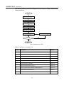
1
About This Manual
Thank you for purchasing the inverter SG1K5TL-31 from Sungrow. We hope that the
device will meet your satisfaction when you use it with your PV plant system.
Aim
This manual contains detailed product information, operation instructions and safety
instructions that must be understood and obeyed during installation and maintenance
of the inverter.
Target Readers
The manual is provided to people who need to install and operate the grid-connected
inverter.
How to Use This Manual
Read this manual and other documents before any work with inverter.
The document must be stored with other documents and be available at all times.
The contents of this manual will be periodically updated or revised if necessary.
However discrepancies cannot be excluded. Please refer to the actual product.
The latest version is available online at www.sungrowpower.com or from the usual
sales channels. Any suggestion, question or criticism is always welcome.
No part of this document may be reproduced, stored in a retrieval system or
transmitted, in any form or by any means, electronic, mechanical, photographic,
magnetic or otherwise, without the prior written permission of Sungrow.
I
Symbols Explanation
Important instructions contained in this manual should be followed during installation,
operation and maintenance of the inverter. And they will be highlighted by these
symbols.
DANGER indicates a hazard with a high level of risk which, if not avoided, will
result in death or serious injury.
WARNING indicates a hazard with a medium level of risk which, if not avoided,
could result in death or serious injury.
CAUTION indicates a hazard with a low level of risk which, if not avoided, could
result in minor or moderate injury.
NOTICE indicates a situation which, if not avoided, could result in equipment or
property damage.
NOTE indicates additional information, emphasized contents or tips to help you solve
problems or save time.
II
Contents
SAFETY AND PRODUCT INFORMATION ................................................................ 1 1 Safety Instructions ................................................................................................. 3 2 Product Introduction .............................................................................................. 9 2.1 Intended Usage .............................................................................................................................. 10 2.2 Principle Description ........................................................................................................................11 2.3 Product Description ........................................................................................................................ 12 2.3.1 Product Appearance ............................................................................................................... 12 2.3.2 Dimensions and Weight of Inverter ........................................................................................ 13 2.3.3 LCD Display Panel ................................................................................................................. 13 2.3.4 DC Switch ............................................................................................................................... 14 INSTALLATION AND MAINTENANCE INFORMATION ....................................... 15 3 Installation Flow ................................................................................................... 17 4 Installing Inverter onto Wall.............................................................................. 19 4.1 Unpacking and Inspection .............................................................................................................. 20 4.2 Nameplate ...................................................................................................................................... 21 4.3 Delivery Contents ........................................................................................................................... 22 4.4 Storage of Inverter .......................................................................................................................... 23 4.5 Selecting Installation Location ........................................................................................................ 23 4.6 Moving Inverter ............................................................................................................................... 26 4.7 Installation Procedure ..................................................................................................................... 27 5 Electrical Connection ........................................................................................... 29 5.1 General Safety Instruction .............................................................................................................. 30 5.2 Terminals Description ..................................................................................................................... 31 5.3 Specifications of Cables.................................................................................................................. 31 5.4 Overview of Electrical Connection .................................................................................................. 32 5.5 Connecting Inverter to PV Arrays ................................................................................................... 33 5.5.1 Safety ..................................................................................................................................... 33 5.5.2 Assembling DC Cable to Connector....................................................................................... 34 5.5.3 DC Wiring Procedure ............................................................................................................. 35 5.6 Connecting Inverter to AC Grid ....................................................................................................... 36 1
5.6.1 Safety ..................................................................................................................................... 36 5.6.2 Assembling AC Cables to Connector ..................................................................................... 38 5.6.3 AC Wiring Procedure .............................................................................................................. 39 5.7 Grounding of Inverter ...................................................................................................................... 40 5.8 Disconnection of Inverter ................................................................................................................ 41 5.9 Connecting Communication Cable ................................................................................................. 42 5.9.1 Monitoring System.................................................................................................................. 42 5.9.2 Connecting RS485 Cable ....................................................................................................... 43 6 Commissioning ..................................................................................................... 45 6.1 Verify before Commissioning .......................................................................................................... 46 6.2 Commissioning Procedure.............................................................................................................. 46 7 Troubleshooting ................................................................................................... 47 7.1 Troubleshooting of LED Indicator ................................................................................................... 48 7.2 Troubleshooting of Faults in LCD Screen ....................................................................................... 49 OPERATION INFORMATION................................................................................... 51 8 Operation of LCD Menu ..................................................................................... 53 8.1 Description of Button Function ....................................................................................................... 54 8.2 Operation Mode of Inverter ............................................................................................................. 54 8.3 Overview of LCD Menu................................................................................................................... 55 8.4 Contrast Adjustment ....................................................................................................................... 56 8.5 Current Running Information .......................................................................................................... 56 8.6 Total Information ............................................................................................................................. 58 8.7 Fault Record ................................................................................................................................... 59 8.8 Parameters Configuration ............................................................................................................... 60 8.8.1 Language Settings ................................................................................................................. 60 8.8.2 Time Settings .......................................................................................................................... 61 8.8.3 Deviation of Energy Settings .................................................................................................. 62 8.8.4 Load Default ........................................................................................................................... 63 8.8.5 Firmware Version ................................................................................................................... 64 8.8.6 Protective Parameters Settings .............................................................................................. 65 8.8.7 Communication Parameters Settings..................................................................................... 66 8.9 Inverter Start and Stop .................................................................................................................... 67 APPENDIX .................................................................................................................. 69 Technical Data ...................................................................................................................................... 69 Exclusion of Liability ............................................................................................................................. 71 About Us ............................................................................................................................................... 72 Contact Information .............................................................................................................................. 72
2
SAFETY AND PRODUCT INFORMATION FOR INSTALLER AND USER
1
2
1
Safety Instructions
About This Chapter
This chapter provides crucial safety instructions about SG1K5TL-31. Please read
“Safety Instructions” carefully before any work with inverter.
3
SG1K5TL-31
User Manual
IMPORTANT SAFETY INSTRUCTIONS
SAVE THESE INSTRUCTIONS
Inverter SG1K5TL-31 has been designed and tested strictly according to the
international safety regulations. However, for electrical and electronic equipment,
safety instructions related to electrical device must be complied with during installation,
commissioning, operation and maintenance. Operation or work performed incorrectly
may result in damage to:
z
The life and well-being of the operator or a third party
z
The inverter and other properties that belong to the operator or a third party
Therefore in order to reduce the risk of personal injury, inverter damage or other
properties damage, the following general safety instructions must be read and always
kept in mind prior to any work. All detailed work-related safety warnings and notes will
be specified at the critical points in corresponding chapter.
All installation and electrical work must only be performed by qualified
personnel. They have
z
been trained specially;
z
already completely read through and understood the manual and other
related documents;
z
been familiar with safety requirements for electrical system.
Technical personnel mentioned above may perform the following work:
z
Install the inverter onto the wall
z
Connect inverter into the PV power system
z
Connect other devices into the PV power system
z
Commission the inverter
z
Maintain and service the inverter
4
Safety Instructions
1
Before Installation
There is a risk of injury due to improperly handling the device!
z
Always follow the instructions contained in the manual when moving and
positioning the inverter.
z
The weight of the equipment can cause injuries, serious wounds, or
bruising if it is not handled correctly.
During Installation
Prior to installing the inverter onto the wall, it is crucial to make certain that the inverter
is not electrically connected.
System performance loss due to bad ventilation!
The equipment requires good quality ventilation during operation. It is essential
to keep the unit upright and nothing covering the heat sink in order to ensure
that the equipment interior is well cooled down.
During Electrical Connection
Lethal voltage exists!
PV arrays will produce electrical energy when exposed to sunlight and thus can
create an electrical shock hazard.
z
Wiring of the PV arrays should only be performed by qualified personnel.
z
PV modules should be covered by opaque materials during wiring.
All cables must be firmly attached, undamaged, properly insulated and
adequately dimensioned.
5
SG1K5TL-31
User Manual
During Inverter Operation
There is a risk of inverter’s damage or personal injury!
Do not disconnect DC connectors while the inverter is under AC load! First
de-energize the equipment from dual power sources and verify that there is no
voltage present.
There is a risk of burn!
Prevent from touching device hot parts (such as heat sink) during operation.
Only LCD display panel and DC switch can be touched during inverter
operation.
Maintenance and Service
z
Any malfunction that may impair inverter safety functions must be repaired
immediately before the inverter is restarted again.
z
Inverter contains no owner serviceable parts inside. Please contact local
authorized personnel if any service work is required.
Servicing of the device in accordance with the manual should never be undertaken in
the absence of proper tools, test equipments and the more recent revision to the
manual which is clearly and thoroughly understood.
6
Safety Instructions
1
There is a risk of inverter damage or personnel injury due to incorrect service
work!
Always keep in mind that inverter is power supplied by dual power source: PV
arrays and utility grid.
Before any service work, you should obey the following procedures.
z
Disconnect inverter from the utility grid side first and then PV arrays;
z
Wait at least ten minutes for inner capacitors discharge completely;
z
Verify that no voltage and current present with appropriate testing device.
Keep non-related person away!
A temporary warning sign and barrier must be posted to keep non-related
person away for any period while performing electrical connection and service
work.
Do not open the enclosure when the inverter is under voltage. There is a highly
unlikely risk of explosion in very specific cases of malfunction. The housing will protect
persons and property from such an explosion, only if it is correctly sealed.
There is a risk of inverter damage if it is improperly serviced.
Use only accessories and spare parts approved by the inverter manufacturer.
And never modify the inverter or other components of the inverter. Otherwise it
will lead to loss of any and all warranty rights.
There is a risk of inverter damage due to electrostatic discharge!
The printed circuit boards contain components sensitive to electrostatic
discharge. Wear a grounding wrist band when handling the boards. Do not
touch the boards unnecessarily during replacement.
7
SG1K5TL-31
User Manual
Others
The selected country settings can be changed by service personnel only!
Unauthorized access to country settings should be prohibited. Alternation of
the country settings may cause a breach of the type-certificate marking.
All safety instructions, warning labels and nameplate on the inverter body:
z
Must be clearly visible;
z
Must not be removed, covered and pasted.
These regulations should also be followed:
z
The regulations related to the electricity fed into grid;
z
The safety instructions related to PV arrays;
z
The safety instructions related to other electrical device.
8
2
Product Introduction
About This Chapter
This chapter introduces intended use, main circuits and constituent parts of the
inverter SG1K5TL-31.
9
SG1K5TL-31
User Manual
2.1 Intended Usage
SG1K5TL-31 is robust, grid-connected, transformer-less and of high conversion
efficiency.
SG1K5TL-31 inverter converts DC power generated from the PV arrays into stable AC
current, and then directly feeds the AC power into the utility grid. It is a crucial unit in
the small-scaled PV power system. An example about intended usage of the inverter
is shown in Fig 2-1.
Where PV arrays need to be grounded of the positive or negative terminal,
SG1K5TL-31 inverter must not be connected in this kind of PV power system.
Fig 2-1 Inverter Applied in the PV Power System
Item
Description
A
PV arrays
B
Inverter SG1K5TL-31
C
Metering device
D
Utility grid
Any other or additional usage is not permitted except the intended use.
The inverter must only be connected to a public utility grid. Local loads (home
appliance, lights, motor loads, etc.) can not be connected between the inverter
and the AC circuit breaker.
10
Product Introduction
2
2.2 Principle Description
The principle design of the SG1K5TL-31--a transformer-less and grid-connected
inverter can be known from the block diagram Fig 2-2.
The PV array voltage connected to the inverter input is always positive and is initially
regulated by the Boost circuit and then converted into alternating current by the full
bridge circuit inverter. The AC connection to the local utility grid is via 3 wires for a
single phase feed point.
Additionally, there is a MPP tracker to ensure that maximum power from PV array can
be utilized. Inside the inverter protective circuit to can trigger AC relay if required for
guaranteeing inverter safely operation and person.
Inverter provides standard interface RS485 for communication. User can look up
running data and configure parameters through human-computer interaction interface
--LCD display panel.
Fig 2-2 Main Circuit Diagram of SG1K5TL-31
11
SG1K5TL-31
User Manual
2.3 Product Description
2.3.1 Product Appearance
Fig 2-3 Product Description
Item
Name
Description
1
LCD display panel
A friendly human-computer interaction interface. Running data and
configuration parameters are displayed in the LCD screen.
2
AC terminal
Inverter feeds power via this terminal.
3
RS485 terminal
Standard communication interface.
4
DC terminal
Interface between inverter and PV arrays.
5
DC switch
Optional component. Disconnect DC current safely.
6
Mounting ear
Hang up the inverter onto the backplate via this mounting ear.
12
Product Introduction
2
2.3.2 Dimensions and Weight of Inverter
W
D
H
Fig 2-4 Dimensions of Inverter
Table 2-1 Dimensions Value
Type
W(mm)
H(mm)
D(mm)
Net weight(kg)
SG1K5TL-31
318
460
151
14
2.3.3 LCD Display Panel
As a friendly human-computer interface, LCD display panel comprises LED indicators,
buttons and LCD screen.
z
LEDs indicate the current state of the inverter
z
The current running information shown in the LCD screen
z
Malfunction records shown in the LCD screen
z
Inverter configuration by pressing the buttons
Fig 2-5 LCD Display Panel
13
SG1K5TL-31
User Manual
Item
Name
Description
1
LCD
screen
LCD screen can display the current state of inverter, current running
information, history information and parameters to be set.
2
Buttons
User can operate the LCD menu of the inverter via the two buttons.
Detailed function is shown in Table 8-1.
3
LED
indicators
They are “RUN” and “FAULT”. User can observe two indicators to get
the current state of inverter. Detailed definition is shown in Table 2-2.
Table 2-2 Description of LED Indicators
Name
State
Description
“RUN”
On
Inverter is running.
Off
Inverter is not running.
On
A malfunction occurs.
Off
A malfunction doesn’t occur.
“FAULT”
The background illumination of LCD screen will go out to save power if there is not
button operation in one minute. You can activate it by pressing any button.
2.3.4 DC Switch
The DC switch is designed for safely disconnecting the DC current if required.
The inverter works automatically if input and output meet the requirements. If you
want to interrupt running or if a malfunction occurs, it can be rotated to the “OFF”
position and then the inverter will cease.
Rotate the DC switch to the “ON” position again before restarting the inverter.
14
INSTALLATION AND MAINTENANCE INFORMATION ONLY FOR INSTALLER
15
16
3
Installation Flow
About This Chapter
This chapter demonstrates installation flow from unpacking to successful
commissioning.
17
SG1K5TL-31
User Manual
The following diagram shows the installation flow of inverter for installer. Please follow
these procedures.
Fig 3-1 Installation Flow Chart
Table 3-1 Description of Installation Flow
Order
Description
Remark
1
Unpacking the inverter and inspection
Section 4.1
2
Read this manual, especially the section on “safety instruction”
Chapter 1
3
Choose the best installation site
Section 4.4
4
Install the inverter against the chosen wall
Section 4.5
5
Connect inverter to PV arrays
Section 5.5
6
Connect inverter to utility grid
Section 5.6
7
Connect the PV system to ground
Section 5.7
8
Connect communication cable for inverter(optional)
Section 5.9
9
Examine before commissioning.
Section 6.1
10
Start up the inverter for the first time
Section 6.2
18
4
Installing Inverter onto Wall
About This Chapter
This chapter provides information about choose installation site and gives
step-by-step procedures to install the inverter onto the wall. And related safety
instructions are also included.
19
SG1K5TL-31
User Manual
4.1 Unpacking and Inspection
The unit is thoroughly tested and inspected strictly before delivery. Although sturdy
packaging is used, damage may still occur during shipping.
z
Check the packing for any visible damage upon receiving.
z
Check the inner contents for damage after unpacking.
z
Check the completeness of delivery contents according to the supplied packing
list.
If there is visible damage to the packaging or the inner contents, or if there is
something missing, contact the unit dealer.
30
2
496
Do not dispose of the original packaging. It is the best choice to store the inverter by
re-using the original packaging.
676
Fig 4-1 Single Inverter in Wooden Crate (unit: mm)
20
Installing Inverter onto Wall
4
4.2 Nameplate
A nameplate is attached to one side of the inverter and the carton respectively. It
provides information on type of inverter, along with the most important specifications,
marks of certification institutions, website and serial number which is available and
identified by Sungrow.
Fig 4-2 Nameplate of Inverter SG1K5TL-31
* Image shown here is indicative only. Actual product you receive may differ.
Item
Description
1
SUNGROW logo and product type
2
Technical data of inverter
3
Marks of certification institutions of inverter
4
Company name, website and origin
21
SG1K5TL-31
User Manual
4.3 Delivery Contents
Fig 4-3 Delivery Contents
Item
Description
A
Inverter
B
Backplate
C
Fastener
D
DC connector
E
AC connector
F
RS485 connector
G
User manual
H
Packing list and test report
I
Quality certificate
22
Installing Inverter onto Wall
4
4.4 Storage of Inverter
If you want to perform decommissioning the inverter, you should choose an
appropriate location to store the inverter.
z
The unit must be stored in original package and desiccant must be left in the
package.
z
The unit must be stored in a clean and dry place to protect against dust and
moisture.
z
The storage temperature should be always between -25℃ and +60℃. And the
storage relative humidity should be always between 0 and 95%.
z
During the storage time, periodically check whether any visible damage by rats.
Replace the package if necessary.
z
After long term storage, local installer or service dept. of Sungrow should perform
a comprehensive test before connecting the inverter into PV power system.
4.5 Selecting Installation Location
Installation shall comply with local regulations and technical rules. Installation shall
comply with the relevant instructions of AS 4777.1.
Selecting an optimal installation location for the inverter is decisive for its operating
safety as well as it expected efficiency and service life.
1. Take the load capacity of the wall into account. The wall (such as concrete wall and
metal structure) should be strong enough to hold the weight of the inverter over a long
period of time.
2. Install the unit where is accessible to install, electrical connection or service.
3. Do not install the inverter where contains flammable
materials or flammable gas in the vicinity of the unit
installation.
23
SG1K5TL-31
User Manual
4. Do not install the unit on wall of flammable materials.
5. Install the unit at eye level for easily buttons operation
and display read.
6. It is suggested that the inverter be installed vertically
with upside up for good heat dissipation.
7. Never install the inverter horizontally, or with a forward tilt, or with a backward tilt or
even with upside down.
8. The inverter unit with IP65 can be installed indoors or outdoors also.
24
Installing Inverter onto Wall
9. The ambient temperature should range from
-25°C to 60°C. When ambient temperature
exceeds 45°C, the power output will reduce.
10. The relative humidity of chosen installation site
should never exceed 95%. Moisture may result in
corrosion and damage to the inner electronic
components.
Max. ambient temperature:
+60°C
Min. ambient temperature:
-25°C
Max. relative humidity:
+95%
No condensing
11. Do not expose the inverter to the direct sunlight. Otherwise inverter will not
operate normally.
Meanwhile avoid exposing to rain or snow to extend its service life despite of IP65
protection degree. Shaded site of the building will be better.
12. Take enough space for convection into consideration during installing multiple
inverters.
25
4
SG1K5TL-31
User Manual
13. Do not install the inverter in a closed cabinet. Otherwise the inverter will not
operate normally.
Closed Cabinet
14. Do not install inverter where children can reach.
15. Do not install inverter in living area. Noise can be produced during running of
inverter, which may affect your daily life.
4.6 Moving Inverter
If the inverter is to be installed, remove the unit from the packaging and move it to the
chosen installation site. During the moving process the instructions below should be
obeyed.
1. Remember the weight of inverter.
2. Grasp the equipment with both hands by means of handles.
3. Do not release the equipment unless it has been secured to the wall firmly.
26
Installing Inverter onto Wall
4
4.7 Installation Procedure
There is a backplate and fasteners supplied to install the inverter. If you don’t want to
use the supplied backplate, you can drill holes referring to its dimension below.
Fig 4-4 Dimensions of Backplate(unit: mm)
Fig 4-5 Dimensions of Fastener Set (unit: mm)
INSTALLATION PROCEDURE:
Step 1: Get the supplied backplate and fasteners from the packaging.
Step 2: Choose the best installation site according to above requirements. Place the
backplate onto the chosen wall and adjust it until it is in a horizontal position.
Step 3: Mark the positions to drill holes using the backplate as the template.
Step 4: Drill six holes at the marks you have made.
27
SG1K5TL-31
User Manual
In order to avoid electrical shock or other injury, inspect existing electronic or
plumbing installations before drilling holes.
Step 5: Fasten the backplate against the wall with the supplied fastener.
Step 6: Lift up the inverter above the backplate and then slide down to make sure that
mounting ear on the back of the inverter fit perfectly together with the backplate.
1
3
2
4
28
5
Electrical Connection
About This Chapter
This chapter proposes step-by-step procedures to perform electrical connection and
related safety instructions.
29
SG1K5TL-31
User Manual
5.1 General Safety Instruction
Improper operation during the wiring process can cause fatal injury to the
operator or unrecoverable inverter damage.
Only qualified personnel can perform the wiring work.
All electrical installations must be in accordance with local and national
electrical codes.
Only after receiving prior approval from the utility company and qualified
personnel installing the inverter, should the inverter be connected to the utility
grid.
All cables must be firmly attached, undamaged, properly insulated and
adequately dimensioned.
These regulations should also be followed:
z
The regulations related to the electricity fed into the grid
z
The safety instructions related to the PV arrays
30
Electrical Connection
5
5.2 Terminals Description
All electrical terminals are located at the bottom of the unit, as the following diagram
shows. Enough space should be kept for electrical connection at the bottom of the
inverter when choosing the installation site.
Fig 5-1 Terminals Description
5.3 Specifications of Cables
All cables for PV power system are equipped with water-proof direct plug-in
connectors. You’ll find these connectors in the package.
For electrical connection in PV power system, specification of all cables used should
meet following requirements. And user should equip these appropriately sized cables.
Table 5-1 Specifications of Cables
Items
No.
Min. cross area
Max. cross area
Recommended
(mm2)
(mm2)
value (mm2)
DC positive cable
1
2.5
4
4
DC negative cable
1
2.5
4
4
L
1
2.5
4
2.5
N
1
2.5
4
2.5
PE
1
2.5
4
2.5
RS485 cable
2
0.5
1.5
0.75
AC
cable
31
SG1K5TL-31
User Manual
5.4 Overview of Electrical Connection
Electrical connections of the inverter include DC connection, AC connection and
communication connection.
This should comply with the National Wiring Rules of Standard AS/NZS 3000.
The requirements in AS 4777.1 and AS/NZS 3000 indicate that a DC isolator must be
used before the inverter.
Fig 5-2 Electrical Connection Diagram
Item
Description
Remark
A
PV arrays
The maximum open-circuit voltage of each PV string is 450V.
B
SolarInfo
logger
It can be ordered from Sungrow.
C
Remote PC
User uses this device to monitor the whole PV system.
D
AC circuit
breaker
Used as a protective device during electrical connection. User equips
this device according to maximum output voltage and current.
E
Utility Grid
Grid voltage is 230V.
32
Electrical Connection
5
5.5 Connecting Inverter to PV Arrays
5.5.1 Safety
As input of the inverter in the PV power system, PV Arrays’ features should be paid
attention to. Please refer to PV module’s data sheet.
When designing PV arrays, following requirements should be met.
Lethal voltage exists!
Do cover the PV arrays with light-tight materials. Exposed to sunlight, PV arrays
will output lethal voltage.
There is a risk of inverter damage.
Make sure that the maximum open voltage of each string is within DC input
voltage range of the inverter. Voltage over 450V can damage to the inverter.
There is a risk of inverter damage.
Make sure that the maximum short current of each string does not exceed
maximum input current. Please refer to chapter “Appendix”.
PV string should have a homogenous structure, including the same type, the same
number, identical tilt and identical orientation.
33
SG1K5TL-31
User Manual
5.5.2 Assembling DC Cable to Connector
All DC cables are equipped with water-proof direct plug-in connectors, which mate
with DC terminals at the bottom of the inverter.
The positive and negative connectors are marked with polarity symbols and should be
equipped with correctly colored cable. Red cable represents DC positive connector
and blue one represents negative.
Step 1: Unscrew the water-proof terminal in the following direction.
Step 2: Strip off insulation layer of DC cable and crimp cable core with hand crimping
pliers. The length of strip insulation is approximate 8mm.
Step 3: Insert appropriately sized DC cable through water-proof terminal.
Step 4: Plug cable gland into connector housing until it makes a clicking sound.
Step 5: Tighten the water-proof terminal in the opposite direction.
When connecting connectors, they will be correctly locked in the mating place.
34
Electrical Connection
5
5.5.3 DC Wiring Procedure
Step 1: Assemble the DC cables to the corresponding connectors at the inverter side.
See “5.5.2 Assembling DC Cable to Connector”.
Step 2: Manually rotate the DC switch at the bottom of the inverter to the “OFF”
position.
Step 3: Check the connection cable of one PV string for the correct polarity and that
the maximum input voltage does not exceed 450V.
Step 4: Measure the DC voltage between the positive terminal of the PV string and
Earth and the DC voltage between the negative terminal of the PV string and Earth. If
the two voltages are constant and not zero, there is an insulation failure somewhere in
this PV string.
Step 5: Plug the DC positive and negative connector into corresponding terminals. If it
makes a clicking sound, DC connector has been attached to the terminals.
35
SG1K5TL-31
User Manual
5.6 Connecting Inverter to AC Grid
5.6.1 Safety
Only after receiving prior approval from the utility company, should you
connect the inverter to the local utility grid.
The grid should meet these following requirements. Otherwise the inverter will
not work.
z
Grid Voltage
z
Grid Frequency
174~274Vac
47~52.5Hz/57~62.5Hz
The grid connection of inverter SG1K5TL-31 is made via 3 wires (L, N and PE).
Feeding power is always single-phase via AC terminal at the bottom of the unit.
An appropriately sized AC circuit breaker is suggested as a protection equipment in
AC connection, as shown in Fig 5-2.
Requirements of Inverter Parallel Grid Connection
If several inverters are operated in parallel connection to grid, there are different
requirements according to different scenarios.
Scenario 1: Several inverters are operated in parallel connection to the single-phase
Low Voltage grid.
Requirements: The sum of all inverters in parallel connection is limited to TEN.
Scenario 2: Several inverters are operated in parallel connection to the three-phase
Low Voltage grid.
36
Electrical Connection
5
Requirements:
z
The sum of all inverters in parallel connection is limited to ten.
n(L1)+n(L2)+n(L3)≤10.
z
Inverters should be distributed as equally as possible between the three phases
with maximum unbalanced load of 4.6kVA.
Scenario 3: Several inverters are operated in parallel connection to low-voltage side
of MV transformer. The high-voltage side of MV transformer is connected to the
Middle Voltage Grid.
Requirements:
z
The sum of all inverters in parallel connection is limited to ten.
n(L1)+n(L2)+n(L3)≤10.
z
Inverters should be distributed as equally as possible between the three phases
at the low-voltage side with maximum unbalanced load of 4.6kVA.
z
The rate voltage on the low-voltage side of transformer must meet the inverter
output electrical specification. A neutral point is necessary and must lead
outwards as neutral conductor.
As mentioned above in the three scenarios, the total number of inverters is
always less than or equal to TEN. If there are inverters more than the limited
value, Inverters may not operate normally.
37
SG1K5TL-31
User Manual
5.6.2 Assembling AC Cables to Connector
Inverter is equipped with water-proof direct plug-in connectors for AC connection,
which mate with AC terminals at the bottom of the inverter.
“L”, “N” and “PE” should be equipped with correctly colored cables for distinguishing.
Please refer to related standards about wiring color.
Step 1: Unscrew the water-proof terminal in the following direction.
Step 2: Insert appropriately sized AC cables through water-proof terminal.
Step 3: Strip off insulation layer of all AC cables. The length of strip insulation is
approximate 5mm.
Step 4: Fix all cables with screwdriver according to markings on the connector,
especially “PE” cable. If a phase wire is connected to the “PE” terminal, it may
permanently destroy the inverter.
Step 5: Pull cables outwards to confirm whether they are installed firmly.
Step 6: Combine the two front-end parts together until there makes a clicking sound.
Step 7: Tighten the water-proof terminal in opposite direction.
38
Electrical Connection
5.6.3 AC Wiring Procedure
Assignment of AC cables should be paid attention to, especially “PE” wire.
Step 1: Assemble AC cables to connector supplied. See “5.6.2 Assembling AC
Cables to Connector”.
Step 2: Make sure that the AC circuit breaker is disconnected and DC switch is
rotated to the “OFF” position.
Step 3: Connect phase cables and “N” cable to AC circuit breaker.
−
Plug AC connector to corresponding AC terminals.
−
Screw AC cables except the “PE” cable to the AC circuit breaker.
Step 4: Connect AC circuit breaker to utility grid.
Step 5: Make sure that all AC cables are firmly installed.
39
5
SG1K5TL-31
User Manual
5.7 Grounding of Inverter
Because of the transformer-less design of the inverter, the DC positive pole and
DC negative pole of the PV arrays are not permitted to be grounded. Otherwise
the inverter can not work.
All non-current carrying exposed metal parts of the equipment and other enclosures in
the PV power system should be grounded (e.g., PV arrays and inverter). For AC side,
it is better to use a continuous irreversibly appropriately sized conductor bare to
ground inverter.
N
40
N
N
Fig 5-3 Grounding of Inverter
Electrical Connection
5
5.8 Disconnection of Inverter
For maintenance work and repairs, the inverter must be switched off.
In order to disconnect the inverter from the AC and DC power sources, you should
proceed with the following procedures. Otherwise you will be exposed to lethal
voltages or the inverter will be damaged.
Step 1: Disconnect the external AC circuit breaker and prevent it from connecting
again.
Step 2: Rotate the DC switch to the “OFF” position.
Please strictly follow the sequence of the above procedures. Otherwise it will
lead to unrecoverable inverter and human damage.
Step 3: Wait about ten minutes until the capacitors inside the inverter have
discharged.
Step 4: Measure AC output of inverter at the AC circuit breaker is voltage free.
Step 5: Measure currents of all DC cables to make sure that there is no current.
Step 6: Release the locking part of DC connectors by pressing on the ribbing of the
locking hooks with nipper pliers and pull outwards.
Step 7: Dismantle AC cables as the opposite procedures in “5.6.2 Assembling AC
Cables to Connector”.
41
SG1K5TL-31
User Manual
5.9 Connecting Communication Cable
5.9.1 Monitoring System
The inverter provides RS485 interface to communicate with remote PC or logger.
User can monitor the inverter’s state via the following types of communication
systems.
z
Through RS485 interface-Data logger
Inverter
Data logger
Fig 5-4 Data Logger Collecting Data
z
Through RS485 interface-Data logger+ PC
Fig 5-5 Communication with PC via Data Logger
z
Through RS485 interface-RS485-232 converter+ PC
Fig 5-6 Communication with PC and RS485-232 Converter
42
Electrical Connection
5
5.9.2 Connecting RS485 Cable
RS485 is communication standard for bidirectional transmission of data between
more than one inverter and a PC or a data logger.
If there is more than one inverter to communicate with a PC or a data logger, it is
crucial to configure communication parameters of each inverter. See “8.8.7
Communication Parameters Settings”. And the maximum number of connected
inverters in a daisy chain is dependent on the converter device. Please refer to the
corresponding manual.
RS485 bus’ requirements to ensure quality of communication:
z
Shielding twist-pair type
z
Shielding layer of RS485 bus should be single-point grounding
SolarInfo logger and RS485-232 converter are optional parts and can be ordered from
Sungrow.
z
Data logger
Inverter 1
Inverter 2
Inverter n
...
SolarInfo logger
A
B
A
B
A
B
A1B1
Step 1: A 120Ω resistance is connected between RS485 A and RS485 B of the first
inverter.
Step 2: Connect RS485 A of Inverter 1 to RS485 A of inverter 2.
Step 3: Connect RS485 B of Inverter 1 to RS485 B of inverter 2.
Step 4: Connect other inverters in the same way.
43
SG1K5TL-31
User Manual
Step 5: Connect RS485 cables of the last inverter to A1 and B1 port of SolarInfo
logger.
z
Data logger+ PC
Step 1: A 120Ω resistance is connected between RS485 A and RS485 B of the first
inverter.
Step 2: Connect RS485 A of Inverter 1 to RS485 A of inverter 2.
Step 3: Connect RS485 B of Inverter 1 to RS485 B of inverter 2.
Step 4: Connect other inverters in the same way.
Step 5: Connect RS485 cables of the last inverter to A1 and B1 port of SolarInfo
logger.
Step 6: Connect RS232 port of SolarInfo logger to RS232 port of PC.
z
PC
Step 1: A 120Ω resistance is connected between RS485 A and B of the first inverter.
Step 2: Connect RS485 A of Inverter 1 to RS485 A of inverter 2.
Step 3: Connect RS485 B of Inverter 1 to RS485 B of inverter 2.
Step 4: Connect other inverters in the same way.
Step 5: Connect RS485 A and B of the last inverter to “RX+” and “TX-” port of
RS232-RS485 converter.
Step 6: Connect RS232 port of RS485-232 converter to RS232 port of PC.
44
6
Commissioning
About This Chapter
This chapter demonstrates how to check before commissioning and operation
procedures.
45
SG1K5TL-31
User Manual
6.1 Verify before Commissioning
Num
Item
Remark
1
Verify whether inverter is fastened onto the wall.
See “4 Installing Inverter onto Wall”.
2
Check whether all cables are undamaged,
properly insulated and adequately dimensioned.
See” 5.3 Specifications of Cables”.
3
Check whether all cables are firmly attached and
correctly.
See “5.5 Connecting Inverter to PV
Arrays” to “5.9 Connecting
Communication Cable”
6.2 Commissioning Procedure
Step 1: Make sure all items above meet demands.
Step 2: Close external AC circuit breaker.
Step 3: Rotate DC switch to the “ON” position.
Suppose that there is sufficient sunlight and no malfunctions:
−
PV arrays initialize and supply DC power to inverter;
−
Inverter verify whether grid conditions are OK.
Step 4: During the startup process, LCD will enter into the below screen, choose the
appropriate language with the buttons and press “ENTER”.
Step 5: Wait for a while and observe state of LED indicators and LCD main screen.
If inverter’s commissioning fails, “FAULT” indicator will be lit. And “state” in the LCD
screen will display type of malfunction. In this case malfunction must be removed and
then repeat step1 to step 4.
If inverter‘s commissioning succeeds, “RUN” indicator will be lit. And “state” in the
LCD screen will display “RUN”.
Step 6: Set time for the inverter according to your local time if successful
commissioning. See “8.8.2 Time Settings”.
46
7
Troubleshooting
About This Chapter
This chapter illustrates troubleshooting of LED indicator and malfunction displayed in
LCD screen.
47
SG1K5TL-31
User Manual
7.1 Troubleshooting of LED Indicator
See “2.3.3 LCD Display Panel” to know definition of LED’s state.
Type of fault
Troubleshooting
LED indicators and
LCD cannot be lit
1. Disconnect the AC circuit breaker.
2. Rotate the DC switch to the “OFF” position.
3. Check the polarity of DC input.
“RUN” indicator
goes out
1. Disconnect the AC circuit breaker.
2. Rotate the DC switch to the “OFF” position.
3. Check the correctness of electrical connection of the inverter. See “5
Electrical Connection”.
4. Check whether the voltage of DC input exceeds start-up voltage of
inverter.
5. If all above conditions are OK, please contact with Sungrow.
“Fault” indicator is lit
1. There is a fault which is not removed yet.
2. Perform troubleshooting in according to fault type in LCD screen. See
“7.2 Troubleshooting of Faults in LCD Screen”.
3. If it can not be solved, please contact with Sungrow.
48
Troubleshooting
7
7.2 Troubleshooting of Faults in LCD Screen
Type of fault
Troubleshooting
Vdc-high
1. Disconnect the AC circuit breaker.
2. Rotate the DC switch to the “OFF” position.
3. Check the voltage of DC side.
4. Restart the inverter until the DC voltage returns to the allowable range.
Vac-low
1. Disconnect the AC circuit breaker.
2. Rotate the DC switch to the “OFF” position.
3. Check the voltage of grid side.
Vac-high
4. If local grid condition exceeds AC requirements of inverter, reset the
protecting parameters. See “8.8.6 Protective Parameters Settings”.
And if local grid voltage exceeds the upper limit value of “Vgrid-max”, or
if local grid voltage is under the lower limit value of “Vgrid-min”, please
contact your local electricity company to adjust the grid voltage.
5. Rotate the DC switch to the “ON” position
6. Close AC circuit breaker to restart the inverter.
7. If the fault still exists, please contact with Sungrow.
F-fault
1. Disconnect the AC circuit breaker.
2. Rotate the DC switch to the “OFF” position.
3. Check the frequency of grid side.
4. If local grid condition exceeds AC demands of inverter, reset the
protective parameters. See “8.8.6 Protective Parameters Settings”.
And if local grid frequency exceeds the upper limit value of “Fgrid-max”,
or if local grid frequency is under the lower limit value of “Vgrid-min”,
please contact your local electricity company to adjust the grid frequency.
5. Rotate the DC switch to the “ON” position
6. Close AC circuit breaker to restart the inverter.
7. If the fault can not be solved, please contact with Sungrow.
PM-fault
If this malfunction occurs, the reasons are very complicated.
1. Disconnect the AC circuit breaker.
2. Rotate the DC switch to the “OFF” position.
3. Check the inner temperature of the inverter and wait for cooling down.
4. Rotate the DC switch to the “ON” position
5. Close AC circuit breaker to restart the inverter.
6. If this malfunction happens again, please contact with Sungrow.
49
SG1K5TL-31
User Manual
Type of fault
Troubleshooting
No-grid
1. Check whether AC circuit breaker is off.
2. Check whether AC cables are all firmly connected.
3. Check whether grid is cut off.
4. If all conditions are OK and this malfunction still occurs in the LCD
screen, please contact with Sungrow.
Temp-flt
1. Check whether AC output power exceeds rated power too much.
2. Reinstall the inverter of appropriate position.
If you have any problems in operating on the inverter, please contact us via
service hotline: +86 551 532 7834/532 7845
email: [email protected]
We need the following information to provide you the best assistance:
y
Type of the inverter
y
Serial number of the inverter
y
Fault name
y
Simple description of the fault phenomenon
50
OPERATION INFORMATION FOR INSTALLER AND USER
51
52
8
Operation of LCD Menu
About This Chapter
This chapter shows operation of LCD menu via buttons to check the records in the
inverter and configure the parameters of the inverter.
53
SG1K5TL-31
User Manual
8.1 Description of Button Function
Inverter offers two buttons to look up running information and configure parameters.
Users should know the button functions before any operation onto inverter.
Table 8-1 Description of Button Function
Name
“
”
Operation
Description
Press less than two
seconds
Move cursor upwards and downwards in the screen
or increase and decrease the setting value. In the
following text, it is called “short press “
“
”
”.”
Press more than two
seconds
Return to parent screen or cancel the command.
Press less than two
seconds
Move cursor left or right in the screen. In the following
Press more than two
seconds
Enter into sub-screen or confirm the command. In the
In the following text, it is called “long press “
text, it is called “short press “
following text, it is called “long press “
””.
””.
””.
8.2 Operation Mode of Inverter
z
Stand-by
Stand-by mode is entered for insufficient input power.
z
Run
After being energized, the inverter tracks the PV arrays’ maximum power point
(MPP) and converts DC power to AC power.
z
Fault
If a fault occurs during operation, the inverter will automatically stop operation,
trigger AC relay and display the fault type in the LCD panel with the “Fault” LED lit.
Once the fault is removed in 5 min., inverter will automatically resume running.
z
Stop
The inverter will stop operation by manually stop through LCD menu; this
condition needs manual restart through LCD menu. During the “Stop” mode, the
inverter will block the driving signals that control the switching PM and disconnect
the inverter from the grid by switching off the AC relay.
z
Com-flt
There is communication malfunction. The both two LED indicators will not be lit.
54
ESC
ENTER
ENTER
55
ENTER
ENTER
ENTER
ENTER
Fig 8-1 Menu Tree-English
ENTER
ENTER
ENTER
ENTER
ENTER
ENTER
ENTER
ENTER
ENTER
ENTER
中
间
器
件
8
Operation of LCD Menu
8.3 Overview of LCD Menu
SG1K5TL-31
User Manual
8.4 Contrast Adjustment
1. Long press “
” to enter into the
“Contrast-adj” menu from the default menu.
2. Short press “
” to decrease the setting
value and short press “
the contrast value.
” to increase
8.5 Current Running Information
Users can view inverter running information conveniently as follows:
1. Short press button “
information.
2. Short press “
” to view current
” to turn pages.
P-ac: inverter output power.
E-day: energy is generated in current day.
E-total: energy has been generated in total.
CO2-total: CO2 weight has been reduced in
total.
E-month: energy has been generated in current
month.
V-grid: grid voltage
I-grid: grid current
F-grid: grid frequency
V-dc: DC voltage of PV string
I-dc: DC current of PV string
T-day: working hour of inverter in current day
h-total: working hour of inverter in total
Temp: inner temperature inside the inverter
State: working status of inverter
56
Operation of LCD Menu
8
User can also view inverter running information via “Current-inform” menu.
1. Long press button “
sub-screen.
” to enter into
2. Short press button “
” to select icon
“Run-inform” and long press button “
to confirm the selection.
”
3. Short press button “
” to select icon
“Current-inform” and confirm the selection.
4. Short press “
57
” to turn pages.
SG1K5TL-31
User Manual
8.6 Total Information
1. Long press button “
sub-screen.
” to enter into
2. Short press button “
” to select icon
“Run-inform” and long press button “
to confirm the selection.
”
3. Short press button “
” to select icon
“Total-inform” and confirm the selection.
4. Short press “
” to turn pages.
E-total: Inverter produces power in total
CO2-total: reduce CO2 Weight
E-month: Inverter produces power in current
month
h-total: total working hour of inverter
58
Operation of LCD Menu
8
8.7 Fault Record
1. Long press button “
sub-screen.
” to enter into
2. Short press button “
” to select icon
“Fault-record” and long press button
“
” to confirm the selection.
3. Short press “
” to turn pages.
Table 8-2 Fault Type Explanation in LCD Screen
Fault type
Explanation
Vdc-high
DC voltage exceeds maximum DC voltage of inverter.
Vdc-low
DCvoltage is less than the lower limit input value.
Vac-high
AC voltage exceeds the upper limit value of grid voltage range.
Vac-low
AC voltage is less than the lower limit value of grid voltage range.
Vbus-high
Bus voltage exceeds the allowable value.
Samp-flt
There is malfunction in the sample circuit.
F-fault
Grid frequency exceeds range.
No-grid
Grid is unavailable or grid malfunction occurs.
PM-fault
PM fault occurs.
Temp-flt
Temperature inside the inverter is too high.
Inverter SG1K5TL-31 an store at most 20 fault records. The latest fault record number
is always 01. The oldest fault record number is always 20(suppose there are 20 fault
records).
59
SG1K5TL-31
User Manual
8.8 Parameters Configuration
If you want to set inverter’s parameters, you have to input correct password.
The default password is 1111.
There are system parameters, running parameters and communication parameters
that users can set.
System parameters include language, time, power-adj, load default, firmware version.
8.8.1 Language Settings
The inverter supports three different languages: English, Chinese and Spanish.
Language can be configured as the following indication.
1. Long press button “
sub-screen.
” to enter into
2. Short press button “
” to select icon
“Set-param” and long press button “
to confirm the selection.
3. Short press “
short press “
1111.
”
” to move cursor and
” to set the password
4. Short press button “
” to select icon
“Sys-param” and long press button “
to confirm the selection.
5. Short press button “
” to select icon
“language” and long press button “
to confirm the selection.
60
”
”
Operation of LCD Menu
6. Short press button “
chosen language.
8
” to select the
8.8.2 Time Settings
If there is deviation between the time in the default screen and your local time, you
should perform the operation “set time”. Where clock set is not 24-hour format, setting
is not valid.
1. Long press button “
sub-screen.
” to enter into
2. Short press button “
” to select icon
“Set-param” and long press button “
to confirm the selection.
3. Short press “
short press “
1111.
”
” to move cursor and
” to set the password
4. Short press button “
” to select icon
“Sys-param” and long press button “
to confirm the selection.
5. Short press button “
“Time” and long press button “
confirm the selection.
61
”
” to select icon
” to
6. Short press button “
” move cursor
and short press button “
correct time.
” to set the
SG1K5TL-31
User Manual
8.8.3 Deviation of Energy Settings
If the accumulative value of “E-tot” by inverter has deviation from the value in the
external metering device, you should adjust the parameter “power-adj”.
1. Long press button “
into sub-screen.
” to enter
2. Short press button “
” to select
icon “Set-param” and long press button
“
” to confirm the selection
3. Short press “
” to move cursor
and short press “ ESC/ ” to set the
password 1111.
4. Short press button “
” to select
icon “Sys-param” and long press button
“
” to confirm the selection.
5. Short press button “
” to select
icon “Power-adj” and long press button
“
” to confirm the selection.
6. Short press button “
” move
cursor and short press button “ ESC/ ” to
set the correct time.
(Power-adj value)= (Real measured
value)-(E-tot reading value).
“+” can be changed to negative symbol “-”.
The adjustable range is from -9999~+9999
kWh. “E-tot” after “Power-adj” adjustment
must not be negative. Otherwise
“Power-adj” settings is not valid.
62
Operation of LCD Menu
8
8.8.4 Load Default
If you perform the operation “Load default”, all running information recorded
will unrecoverable cleared and all parameters will return to the default value
except protective parameters and time.
1. Long press button “
sub-screen.
” to enter into
2. Short press button “
” to select icon
“Set-param” and long press button “
to confirm the selection.
3. Short press “
short press “
1111.
”
” to move cursor and
” to set the password
4. Short press button “
” to select icon
“Sys-param” and long press button “
to confirm the selection.
”
5. Short press button “
” to select icon
“Load-default” and long press button
“
” to confirm the selection.
6. Input password “1111”.
If users restart the inverter after “Load default”,
there is a language selection screen.
63
SG1K5TL-31
User Manual
8.8.5 Firmware Version
User can not set this parameter.
1. Long press button “
sub-screen.
” to enter into
2. Short press button “
” to select icon
“Set-param” and long press button “
to confirm the selection.
3. Short press “
short press “
1111.
”
” to move cursor and
” to set the password
4. Short press button “
” to select icon
“Sys-param” and long press button “
to confirm the selection.
5. Short press button “
”
” to select icon
“Firmware” and long press button “
to confirm the selection.
”
6. This screen displays software version of this
inverter.
64
Operation of LCD Menu
8
8.8.6 Protective Parameters Settings
1. Long press button “
sub-screen.
” to enter into
2. Short press button “
” to select
icon “Set-param” and long press button
“
” to confirm the selection.
3. Short press “
and short press “
1111.
” to move cursor
” to set the password
4. Short press button “
” to select
icon “Pro-param” and long press button
“
” to confirm the selection.
5. Short press button “
” to move
cursor and short press “
” to set
appropriate protective parameters.
Table 8-3 Protective Parameters Range
Parameter
Simple explanation
Adjustable range
Default value
Vgrid-max
Maximum AC voltage
240V-274V
270V
Vgrid-min
Minimum AC voltage
174V-215V
180V
Fgrid-max
Maximum AC frequency
50.2Hz-52.5Hz
51.5Hz
60.5Hz-62.5Hz
61.0Hz
47.0Hz-49.5Hz
47.5Hz
57.0Hz-59.5Hz
59.0Hz
Fgrid-min
Minimum AC frequency
65
SG1K5TL-31
User Manual
8.8.7 Communication Parameters Settings
1. Long press button “
sub-screen.
” to enter into
2. Short press button “
” to select
icon “Set-param” and long press button
“
” to confirm the selection.
3. Short press “
and short press “
1111.
” to move cursor
” to set the password
4. Short press button “
” to select
icon “Com-param” and long press button
“
” to confirm the selection.
5. Short press button “
” to move
cursor and short press “
” to set
appropriate communication parameters.
Each inverter should have different address and have same baud rate to ensure
good communication.
Address range:
1~247
Baud rate:
1200,2400,4800,9600
Default protocol:
Modbus
66
Operation of LCD Menu
8
8.9 Inverter Start and Stop
1. Long press button “
sub-screen.
” to enter into
2. Short press button “
” to select
icon “Set-param” and long press button
“
” to confirm the selection.
3. Short press “ ESC/
long press “
selection.
67
” to move cursor and
” to confirm the
SG1K5TL-31
User Manual
68
APPENDIX Technical Data
Technical Specifications
SG1K5TL-31
DC Side Data
Max. DC Power
1600W
Max. Input Current
10A
MPP Voltage Range
150~380V
Max. DC Voltage
450V
Min. DC Voltage
150V
Start Voltage
170V
AC Side Data
Nominal AC Power
1500W
Max. AC Output Current
8A
Rated Grid Voltage
230Vac
AC Voltage Range
174~274Vac
Rated Grid Frequency
50Hz/60Hz
AC Frequency Range
47~52.5Hz/57~62.5Hz
Output Current THD
<3% (at nominal power)
DC Current Injection
<0.5% of rated inverter output current
Power Factor
≥0.99 (at nominal power)
System
Max. Efficiency
95%
Euro. Efficiency
94%
69
Ingress Class
IP65
Power Consumption at Night
0W
Operating Temperature
-25℃~+60℃
Cooling Method
Natural cooling
Relative Humidity
0~95%, non-condensing
Max. Working Altitude
2000m
DC Switch
Optional
Technical Specifications
SG1K5TL-31
Mechanical Data
Dimensions(W x H x D)
318*460*151mm
Weight
14kg
Display and Communication
Display
LCD
Communication(Standard)
RS485
Communication(Optional)
Ethernet
70
Exclusion of Liability
The content of these documents is periodically checked and revised, when necessary,
please call us or check our website www.sungrowpower.com for the latest information.
However discrepancies cannot be excluded. No guarantee is made for the
completeness of these documents. Please contact our company or distributors to get
the latest version.
Guarantee or liability claims for damages of any kind are excluded if they are caused
by one or more of the following:
z
Improper or inappropriate use or install of the product
z
Installing or operating the product in an unintended environment
z
Installing or operating the product when ignoring relevant safety regulations in
the deployment location
z
Ignoring safety warnings and instructions contained in all documents relevant to
the product
z
Installing or operating the product under incorrect safety or protection conditions
z
Altering the product or supplied software without authority
z
The product malfunctions due to operating attached or neighboring devices
beyond allowed limit values
z
In case of unforeseen calamity or force majeure
The use of supplied software produced by Sungrow Power Supply Co., Ltd. is subject
to the following conditions:
z
Sungrow Power Supply Co., Ltd. rejects any liability for direct or indirect
damages arising from the use of the SolarInfo software. This also applies to the
provision or non-provision of support activities.
z
Using the SolarInfo software for commercial purposes is prohibited.
z
Decompiling, decoding or destroying the original program, including SolarInfo
software and the embedded software, is prohibited.
71
About Us
Sungrow power supply is a China-leading manufacturer of various power electronics
products for renewable energy generation systems. Our products include converters,
inverters, battery chargers and other power supplies for distributable generation
system in both grid-connected and stand-alone applications. The power rating of
Sungrow products covers from several hundred watt to large mega-watt systems.
The pursuit of Sungrow is to help our customers acquire stable and clean power with
minimum cost, maximum reliability and enhanced safety.
Contact Information
If you have any questions about this product, our hotline will be happy to assist you.
Please keep the following data when contacting Sungrow.
Company:
Sungrow Power Supply Co., Ltd.
Website:
www.sungrowpower.com
Contact:
Mr. Henry (Director of International Trade)
Email:
[email protected], [email protected]
Address:
No.2 Tianhu Rd. New & High Technology Industrial Development Zone, Hefei,
P.R.China
Zip:
230088
Telephone: +86 551 532 7834, +86 551 532 7845
Fax:
+86 551 532 7856
72
Sungrow Power Supply Co., Ltd.
Add: No.2 Tianhu Rd., New & High Technology Industrial
Development Zone, Hefei, P.R.China.
Contact: Mr. Henry (Director of International Trade)
Zip: 230088
Specifications subject to change without notice.
Web: www.sungrowpower.com
E-mail: [email protected]
Tel: +86 551 532 7834/532 7845
Fax: +86 551 532 7856