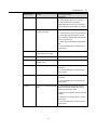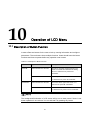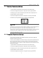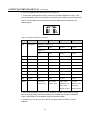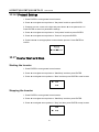
1
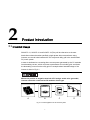
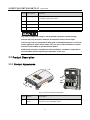
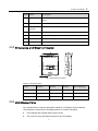
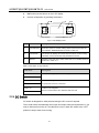
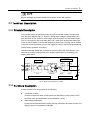
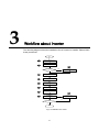
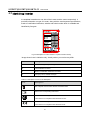
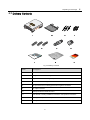
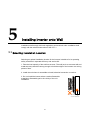
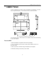
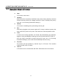
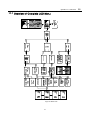
About This Manual
This manual is for the inverter SG2K5TL-31, SG3KTL-31 and SG4KTL-31. These
inverters are grid-connected, transformer-less, robust and of high conversion
efficiency. The device will bring you more profits from PV power system.
Aim
The manual contains information about the inverter, which will provide you guidelines
to connect the inverter into the PV power system and operate the inverter.
Related Documents
The manual cannot include complete information about the PV system. You will get
the additional information about other devices at www.sungrowpower.com/download
or via webpage of device manufacturer.
Target Group
The manual is targeted to technical personnel who is responsible for inverter
installation and commissioning in the PV power system and inverter owner who will
perform daily LCD operation.
How to Use This Manual
Read this manual and other related documents before any work with the inverter.
Documents must be stored carefully and available at all times.
The contents of the manual due to the product development will be periodically
updated or revised. It is probably that there are changes of manual in subsequent
inverter edition. The latest manual can be acquired via visiting the web page
www.sungrowpower.com.
I Symbols Explanation
Important instructions contained in this manual should be followed during installation,
operation and maintenance of the inverter. And they will be highlighted by these
symbols.
DANGER indicates a hazard with a high level of risk which, if not avoided, will
result in death or serious injury.
WARNING indicates a hazard with a medium level of risk which, if not avoided,
could result in death or serious injury.
CAUTION indicates a hazard with a low level of risk which, if not avoided, could
result in minor or moderate injury.
NOTICE indicates a situation which, if not avoided, could result in equipment or
property damage.
NOTE indicates additional information, emphasized contents or tips to help you solve
problems or save time.
II
Symbols on the Inverter Body
This symbol indicates that you should wait at least 10 minutes after
disconnecting the inverter from the utility grid and from the PV input before
touching any inner live parts.
Hot surface! In order to reduce the risk of burns, do not touch device hot
surface when the device is running.
Look over the user manual before any operation onto the inverter!
The installation and service of the inverter unit can only be performed by
qualified personnel.
Do not disconnect DC connectors from the unit under load!
III IV
Contents
1 Safety Instructions ................................................................................................. 1 2 Product Introduction .............................................................................................. 7 2.1 Intended Usage ................................................................................................................................ 7 2.2 Product Description .......................................................................................................................... 8 2.2.1 Product Appearance ................................................................................................................. 8 2.2.2 Dimensions and Weight of Inverter .......................................................................................... 9 2.2.3 LCD Display Panel ................................................................................................................... 9 2.2.4 DC Switch ............................................................................................................................... 10 2.3 Technical Description .......................................................................................................................11 2.3.1 Principle Description................................................................................................................11 2.3.2 Functions Description ..............................................................................................................11 3 Workflow about Inverter .................................................................................... 13 4 Unpacking and Storage ....................................................................................... 15 4.1 Unpacking and Inspection .............................................................................................................. 15 4.2 Identifying Inverter .......................................................................................................................... 16 4.3 Delivery Contents ........................................................................................................................... 17 4.4 Storage of Inverter .......................................................................................................................... 18 5 Installing Inverter onto Wall.............................................................................. 19 5.1 Selecting Installation Location ........................................................................................................ 19 5.2 Moving Inverter to Installation Site ................................................................................................. 22 5.3 Installation Procedure ..................................................................................................................... 23 6 Electrical Connection ........................................................................................... 25 6.1 Terminals Description ..................................................................................................................... 25 6.2 Simplified Electrical Connection Diagram....................................................................................... 26 6.3 Connecting Inverter to AC Grid ....................................................................................................... 27 6.3.1 AC Side Requirements ........................................................................................................... 27 6.3.2 Assembling AC Connector with Cables .................................................................................. 29 6.3.3 Connecting Inverter to AC Grid .............................................................................................. 31 6.4 Connecting Inverter to PV Arrays ................................................................................................... 32 6.4.1 Assembling DC Cable to Connector....................................................................................... 32 6.4.2 Wiring Procedures .................................................................................................................. 34 6.5 PV System Grounding .................................................................................................................... 35 I 6.6 Communication Connection............................................................................................................ 36 6.6.1 Communication Types ............................................................................................................ 36 6.6.2 RS485 Communication Connection ....................................................................................... 36 7 Commissioning ..................................................................................................... 39 7.1 Verify before Commissioning .......................................................................................................... 39 7.2 Commissioning Procedures ............................................................................................................ 39 8 Disconnection of Inverter ................................................................................... 41 9 Troubleshooting ................................................................................................... 43 9.1 Troubleshooting of LED Indicator ................................................................................................... 43 9.1.1 Troubleshooting of LED Indicator ........................................................................................... 43 9.1.2 Troubleshooting of Faults in LCD Screen .............................................................................. 44 9.2 Maintenance ................................................................................................................................... 46 9.2.1 Cleaning the Cabinet .............................................................................................................. 46 9.2.2 Cleaning the Heat Sink........................................................................................................... 46 9.2.3 Battery Maintenance .............................................................................................................. 46 10 Operation of LCD Menu ................................................................................... 49 10.1 Description of Button Function ...................................................................................................... 49 10.2 Operation Mode of Inverter ........................................................................................................... 50 10.3 Overview of Complete LCD Menu ................................................................................................ 51 10.4 The Default Screen ....................................................................................................................... 52 10.5 Contrast Adjustment...................................................................................................................... 52 10.6 Current Running Information ........................................................................................................ 53 10.7 Historical Information .................................................................................................................... 53 10.7.1 Running Record.................................................................................................................... 53 10.7.2 Fault Record ......................................................................................................................... 54 10.8 Language Settings ........................................................................................................................ 55 10.9 Time Settings ................................................................................................................................ 55 10.10 Deviation of E-tot Adjustment ...................................................................................................... 56 10.11 Load Default Settings .................................................................................................................. 57 10.12 Firmware Version ........................................................................................................................ 57 10.13 Auto-test (Only for Italy) .............................................................................................................. 58 10.14 Running Parameters Settings ..................................................................................................... 59 10.15 Protective Parameters Settings .................................................................................................. 59 10.16 Communication Parameters Settings ......................................................................................... 61 10.16.1 Address Settings ................................................................................................................. 61 10.16.2 Protocol Settings................................................................................................................. 62 10.17 Inverter Start and Stop ................................................................................................................ 62 II APPENDIX .................................................................................................................. 63 Electrical Specifications ........................................................................................................................ 63 Temperature Derating Curve ............................................................................................................... 65 Exclusion of Liability ............................................................................................................................. 66 About Us ............................................................................................................................................... 67 III IV 1
Safety Instructions
IMPORTANT SAFETY INSTRUCTIONS
SAVE THESE INSTRUCTIONS
Inverter SG2K5TL-31, SG3KTL-31 and SG4KTL-31 have been designed and tested
strictly according to the international safety regulations. However, for electrical and
electronic equipment, safety instructions related to electrical device must be complied
with during installation, commissioning, operation and maintenance. Operation or
work performed incorrectly may result in damage to:
z
The life and well-being of the operator or a third party
z
The inverter and other properties that belong to the operator or a third party
Therefore in order to reduce the risk of personal injury, inverter damage or other
properties damage, the following general safety instructions must be read and always
kept in mind prior to any work. All detailed work-related safety warnings and notes will
be specified at the critical points in corresponding chapter.
All installation and electrical work must only be performed by qualified
personnel. They have
z
been trained specially;
z
already completely read through and understood the manual and other
related documents;
z
been familiar with safety requirements for electrical system.
Technical personnel mentioned above may perform the following work:
1 SG2K5TL/SG3KTL/SG4KTL-31
User Manual
z
Install the inverter onto the wall
z
Connect inverter into the PV power system
z
Connect other devices into the PV power system
z
Commission the inverter
z
Maintain and service the inverter
Before Installation
There is a risk of injury due to improperly handling the device!
z
Always follow the instructions contained in the manual when moving and
positioning the inverter.
z
The weight of the equipment can cause injuries, serious wounds, or
bruising if it is not handled correctly.
During Installation
Prior to installing the inverter onto the wall, it is crucial to make certain that the inverter
is not electrically connected.
System performance loss due to bad ventilation!
The equipment requires good quality ventilation during operation. It is essential
to keep the unit upright and nothing covering the heat sink in order to ensure
that the equipment interior is well cooled down.
During Electrical Connection
Lethal voltage exists!
PV arrays will produce electrical energy when exposed to sunlight and thus can
create an electrical shock hazard.
z
Wiring of the PV arrays should only be performed by qualified personnel.
z
PV modules should be covered by opaque materials during wiring.
2 Safety Instructions
1
All cables must be firmly attached, undamaged, properly insulated and
adequately dimensioned.
During Inverter Operation
There is a risk of inverter’s damage or personal injury!
Do not disconnect DC connectors while the inverter is under AC load! First
de-energize the equipment from dual power sources and verify that there is no
voltage present.
There is a risk of burn!
Prevent from touching device hot parts (such as heat sink) during operation.
Only LCD display panel and DC switch can be touched during inverter
operation.
Maintenance and Service
z
Any malfunction that may impair inverter safety functions must be repaired
immediately before the inverter is restarted again.
z
Inverter contains no owner serviceable parts inside. Please contact local
authorized personnel if any service work is required.
Servicing of the device in accordance with the manual should never be undertaken in
the absence of proper tools, test equipments and the more recent revision to the
manual which is clearly and thoroughly understood.
3 SG2K5TL/SG3KTL/SG4KTL-31
User Manual
There is a risk of inverter damage or personnel injury due to incorrect service
work!
Always keep in mind that inverter is power supplied by dual power source: PV
arrays and utility grid.
Before any service work, you should obey the following procedures.
z
Disconnect inverter from the utility grid side first and then PV arrays;
z
Wait at least ten minutes for inner capacitors discharge completely;
z
Verify that no voltage and current present with appropriate testing device.
Keep non-related person away!
A temporary warning sign and barrier must be posted to keep non-related
person away for any period while performing electrical connection and service
work.
Do not open the enclosure when the inverter is under voltage. There is a highly
unlikely risk of explosion in very specific cases of malfunction. The housing will protect
persons and property from such an explosion, only if it is correctly sealed.
There is a risk of inverter damage if it is improperly serviced.
Use only accessories and spare parts approved by the inverter manufacturer.
And never modify the inverter or other components of the inverter. Otherwise it
will lead to loss of any and all warranty rights.
There is a risk of inverter damage due to electrostatic discharge!
The printed circuit boards contain components sensitive to electrostatic
discharge. Wear a grounding wrist band when handling the boards. Do not
touch the boards unnecessarily during replacement.
4 Safety Instructions
Others
The selected country settings can be changed by service personnel only!
Unauthorized access to country settings should be prohibited. Alternation of
the country settings may cause a breach of the type-certificate marking.
All safety instructions, warning labels and nameplate on the inverter body:
z
Must be clearly visible;
z
Must not be removed, covered and pasted.
These regulations should also be followed:
z
The regulations related to the electricity fed into grid;
z
The safety instructions related to PV arrays;
z
The safety instructions related to other electrical device.
5 1
SG2K5TL/SG3KTL/SG4KTL-31
User Manual
6 2
Product Introduction
2.1 Intended Usage
SG2K5TL-31, SG3KTL-31 and SG4KTL-31(They will be referred to as inverter
hereinafter unless otherwise specified), single-phase without transformer string
inverters, are crucial units between the PV arrays and utility grid in the small-scaled
PV power system.
Inverter is dedicated to converting direct current power generated by the PV modules
into alternating current, which conforms to parameters of local utility grid, and feeds
the alternating current into the utility grid. An example about intended usage of the
inverter is show in Fig 2-1.
Where the positive or negative terminal of PV strings needs to be grounded,
inverter cannot be connected to PV modules of this type.
A
B
C
Fig 2-1 Inverter Applied in the PV Power System
7 D
SG2K5TL/SG3KTL/SG4KTL-31
User Manual
Item
Description
Remark
A
PV strings
monocrystalline silicon; polycrystalline silicon and thin-film without
grounding of protection class II
B
Inverter
SG2K5TL-31, SG3KTL-31 or SG4KTL-31 involved
C
Metering device
meter cupboard with power distribution system
D
Utility grid
TT, TN
Any other or additional usage is not permitted except the intended usage.
Inverter may only accept PV modules of Protection Class II as its input.
Inverter may only be connected to utility grid via distribution board. Local loads
(home appliance, lights, motor loads, etc.) can not connected between inverter
and AC circuit breaker on the distribution board.
Additionally, the unit is intended for fixed installation. Located on a part that is
not removable without impairing the operation of the unit.
2.2 Product Description
2.2.1 Product Appearance
Fig 2-2 Product Components Description
Item
Name
Description
1
LCD display
panel
Inverter operation data viewing and parameters configuration can be
performed on the LCD display panel.
8 Product Introduction
2
Item
Name
Description
2
DC switch
Optional component. It is designed for safely disconnecting DC
current.
3
DC terminals
There are three pairs of DC terminals between PV arrays and inverter.
4
RS485
terminals
Standard communication interface.
5
AC terminal
Inverter feeds power to utility grid via this terminal.
6
Mounting ear
It is used for hanging inverter onto the backplate.
7
Heat sink
It is used for cooling down the unit temperature during operation.
8
Fan
Only SG4KTL-31 is equipped with fan to help air ventilation.
2.2.2 Dimensions and Weight of Inverter
H
Fig 2-3 Dimensions of Inverter
Table 2-1 Dimensions Value
Type
W(mm)
H(mm)
D(mm)
Net weight(kg)
SG2K5TL-31
420
555
179
20
SG3KTL-31
420
555
179
20
SG4KTL-31
420
555
179
20
2.2.3 LCD Display Panel
As a friendly human-computer interaction interface, LCD display panel comprises
LED indicators, buttons and LCD display screen on inverter front panel.
z
LEDs indicate the working status of the inverter
z
The current running information shown on the LCD display
9 SG2K5TL/SG3KTL/SG4KTL-31
User Manual
z
Malfunction records shown on the LCD display
z
Inverter configuration by pressing the buttons
Fig 2-4 LCD Display Panel
No.
Name
Description
1
LED indicators
“RUN” and “FAULT”. Inverter working status can be known from the
two indicators. Detailed definition is shown in Table 2-2.
2
LCD Screen
LCD screen can display the current state of inverter, current running
information, history information and parameters to be set.
3
Buttons
Navigate in the LCD menu, select values and so on. Detailed functions
are shown in Table 10-1.
Table 2-2 Description of LED Indicator
LED State
Description
“RUN”: on
Inverter is feeding AC power to the utility grid.
“FAULT”: off
“RUN”: off
“FAULT”: on
“RUN”: off
“FAULT”: off
A malfunction happens;
Or a protection function is activated.
Inverter is not energized;
There is communication error between DSP and LCD.
2.2.4 DC Switch
DC switch is designed for safely disconnecting the DC current if required.
The inverter works automatically when input and output meet the requirements. If you
want to interrupt its running or if a malfunction occurs, rotate DC switch to the “OFF”
position to stop inverter from running.
10 2
Product Introduction
Before restarting the inverter, rotate the DC switch to the “ON” position.
2.3 Technical Description
2.3.1 Principle Description
The principle design of transformer-less and grid-connected inverter can be known
from the block diagram Fig 2-5. Three PV strings input voltage is transmitted to DC
BUS via Boost circuit. And then a full bridge circuit converts it into sinusoidal current.
The AC connection to the local utility grid is via 3 wires for a single phase feed point.
There is a MPP tracker to ensure that maximum power from PV string can be utilized.
Inside the inverter protective circuit to can trigger AC relay if required for guaranteeing
inverter safely operation and person.
Standard interface RS485 are provided for communication with other devices. You
can look up inverter running status and configure parameters by navigating LCD
display panel menu.
Functional Safety
and Protective Circuit
MPPT
DC Switch
L
N
Boost
Full Bridge
Communication Interface RS485
Relay 1
Relay 2
PE
LCD Display Panel
Fig 2-5 Main Circuit Diagram of Inverter
2.3.2 Functions Description
Inverter functions can be grouped as the following:
z
Conversion function
Inverter converts the direct current power into alternating current power, which
conforms to the grid requirement of its installation country.
z
Data storage and display
Inverter stores essential data including running information and fault records, and
displays them on integrated LCD display.
11 SG2K5TL/SG3KTL/SG4KTL-31
z
User Manual
Parameters configuration
Inverter provides various parameters configuration for optimal operation.
z
Communication interface
Standard RS485 interface for connecting other monitoring devices into the PV
system is included.
z
Protection functions include
−
reverse polarity protection
−
short circuit protection
−
insulation resistance to ground surveillance
−
inverter output voltage surveillance
−
inverter output frequency surveillance
−
residual current protection
−
DC component of AC output current surveillance
−
anti-islanding phenomena protection
−
ambient temperature surveillance
12 3
Workflow about Inverter
The following diagram shows the installation flow of inverter for installer. Please follow
these procedures.
Start
1
Unpacking and Inspection
2
Read User Manual
3
Install Immediately?
No
Storage
Yes
4
Mounting Location Selection
5
Moving Inverter
6
Mounting the Inverter
7
Electrical Connection
8
Check before Commissioning
9
Commissioning
10
Success?
Troubleshooting
No
Yes
End
Fig 3-1 Installation Flow Chart
13 SG2K5TL/SG3KTL/SG4KTL-31
User Manual
Table 3-1 Description of Installation Flow
Order
Description
Remark
1
Unpacking and inspection
Section 4.1
2
Read this manual, especially the section on “safety instruction”
Chapter 1
3
Store the inverter unit if not installed immediately
Section 4.4
4
Choose the best installation site
Section 5.1
5
Moving the inverter to installation site
Section 5.2
6
Install the inverter against the chosen wall
Section 5.3
7
Electrical connections include DC, AC, ground and
communication(optional)connection
Section 6.3~6.6
8
Examine before commissioning
Section 7.1
9
Start up inverter and configure corresponding parameters
Section 7.2
10
Troubleshooting
Section 9.1
14 4
Unpacking and Storage
4.1 Unpacking and Inspection
The unit is thoroughly tested and inspected strictly before delivery. Although sturdy
packaging is used, damage may still occur during shipping.
z
Check the packing for any visible damage upon receiving.
z
Check the inner contents for damage after unpacking.
z
Check the completeness of delivery contents according to the supplied packing
list.
If there is visible damage to the packaging or the inner contents, or if there is
something missing, contact the unit dealer.
Do not dispose of the original packaging. It is the best choice to store the inverter by
re-using the original packaging.
387
57
62
5
0
313
710
775
Fig 4-1 Single Inverter in Original Carton and Wooden Crate (unit:mm)
15 SG2K5TL/SG3KTL/SG4KTL-31
User Manual
4.2 Identifying Inverter
A nameplate is attached to one side of the inverter and the carton respectively. It
provides information on type of inverter, along with the most important specifications,
marks of certification institutions, website and serial number which is available and
identified by Sungrow.
Fig 4-2 Nameplate of Inverter SG4KTL-31(without serial number)
*Image shown here is indicative only. Actual product you receive may differ.
Item
Description
1
SUNGROW logo and product type
2
Technical data of inverter
3
Marks of certification institutions of inverter
4
Company name, website and origin
Table 4-1 Description of Icons on the Nameplate
Icon
Description
Don’t dispose of the inverter with the household waste.
Refer to the corresponding instructions.
TUV mark of conformity.
The inverter is in compliance with directives of TUV.
CE mark of conformity.
The inverter is in compliance with directives of CE.
16 Unpacking and Storage
4.3 Delivery Contents
Fig 4-3 Delivery Contents
Item
Description
A
Inverter unit
B
Backplate is used for mounting inverter onto the wall
C
Expansion bolts for fastening backplate onto concrete wall
D
Fastener set for installing inverter onto metal frame
E
PV input connectors, including positive and negative connectors
F
AC output connector
G
Waterproof Ethernet male-connector
H
User Manual, including installation instructions and operation instructions
I
Packing list and product test report
J
Quality certificate
17 4
SG2K5TL/SG3KTL/SG4KTL-31
User Manual
4.4 Storage of Inverter
Where the inverter may not be installed immediately or inverter needs to be stored
under certain condition, store the unit as the following indications:
z
The unit must be packed into original carton and desiccant must be left inside. If
the original packaging is not accessible, an equivalent carbon which is able to
support the unit weight and size can be used.
z
The packing should be sealed by adhesive tape.
z
The unit must be stored in a clean and dry place to protect against dust and
moisture.
z
The storage temperature should be always between -25℃~60℃. And the
storage relative humidity should be always between 0 and 95%.
z
It is very important to keep the packing away from chemicals. Otherwise it will
lead to corrosion.
z
During the storage time, periodically check any visible damage by rats and other
rodents. Replace the packaging if necessary.
z
The packaging should be kept upright.
z
If there is more than one inverter to be stored, the maximum layers for original
carton is three.
z
After long term storage, local installer or service dept. of Sungrow should perform
a comprehensive test before connecting the inverter into PV power system.
18 5
Installing Inverter onto Wall
Installation shall comply with local regulations and technical rules. Installation shall
comply with the relevant instructions of AS 4777.1.
5.1 Selecting Installation Location
Selecting an optimal installation location for the inverter is decisive for its operating
safety as well as it expected efficiency and service life.
1. Take the load capacity of the wall into account. The wall (such as concrete wall and
metal structure) should be strong enough to hold the weight of the inverter over a long
period of time.
2. Install the unit where is accessible to install, electrical connection or service.
3. Do not install the inverter where contains flammable
materials or flammable gas in the vicinity of the unit
installation.
Flammable material or gas
near the installation
19 SG2K5TL/SG3KTL/SG4KTL-31
User Manual
4. Do not install the unit on wall of flammable materials.
Flammable wall material
5. Install the unit at eye level for easily buttons operation
and display read.
6. It is suggested that the inverter be installed vertically
with upside up for good heat dissipation.
7. Never install the inverter horizontally, or with a forward tilt, or with a backward tilt or
even with upside down.
With a forward tilt
With a backward tilt
Horizontally
With upside down
8. The inverter unit with IP65 can be installed indoors or outdoors also.
20 Installing Inverter onto Wall
9. The ambient temperature should range from
-25°C to 60°C. When ambient temperature
exceeds 45°C, the power output will reduce.
10. The relative humidity of chosen installation site
should never exceed 95%. Moisture may result in
corrosion and damage to the inner electronic
components.
5
Max. ambient temperature:
+60°C
Min. ambient temperature:
-25°C
Max. relative humidity:
+95%
No condensing
11. Do not expose the inverter to the direct sunlight. Otherwise inverter will not
operate normally. Meanwhile avoid exposing to rain or snow to extend its service life
despite of IP65 protection degree. Shaded site of the building will be better.
12. Take enough space for convection into consideration during installing multiple
inverters.
13. Do not install the inverter in a closed cabinet. Otherwise, the inverter will not
operate normally.
21 SG2K5TL/SG3KTL/SG4KTL-31
User Manual
14. Do not install inverter where children can reach.
15. Do not install inverter in living area. Noise can be produced during running of
inverter, which may affect your daily life.
5.2 Moving Inverter to Installation Site
If the inverter is to be installed, remove the unit from the packaging and move it to the
chosen installation site. During the moving process the instructions below should be
obeyed.
1. Remember the weight of inverter.
2. Grasp the equipment with both hands by means of handles.
3. Do not release the equipment unless it has been secured to the wall firmly.
22 Installing Inverter onto Wall
5
5.3 Installation Procedure
Inverter is installed onto the wall by means of backplate in the packaging. If you don’t
use the supplied backplate, you can drill holes refer to its dimension below.
M10
45
Fig 5-1 Dimensions of Backplate and Fastener(unit: mm)
In the following pages we will introduce how to install the inverter onto the wall using
the provided backplate.
Concrete Wall
1. Remove backplate and expansion bolts from the packaging.
2. Place the backplate onto the chosen concrete wall and adjust it until it is in a
horizontal position.
3. Mark the positions to drill holes using the backplate as the template.
4. Drill holes according to the marks you have made.
23 SG2K5TL/SG3KTL/SG4KTL-31
User Manual
Mark positions
Drill holes
In order to avoid electrical shock or other injury, inspect existing electronic or
plumbing installations before drilling holes.
5. Attach the backplate to the wall with the supplied expansion bolt set. The torque for
fastening the nut should be at least 35 Nm.
6. Lift up the inverter above the backplate and then slide down, making sure that the
two mounting ears on the back of the inverter and counterparts of the backplate
engage perfectly.
Install backplate
Hang inverter
Mounting
ear
1
2
4
5
Backplate
3
6
24 6
Electrical Connection
Once the inverter is firmly attached to the appropriate location, it can be connected
into the PV power system.
Improper operation during the wiring process can cause fatal injury to the
operator or unrecoverable inverter damage. Only qualified personnel can
perform the wiring work.
Prior to any electrical connection, keep in mind that inverter has dual power supplies.
It is mandatory for technical personnel to wear personal protective equipments:
helmet, footwear and gloves during the electrical work.
6.1 Terminals Description
All electrical terminals are located at the bottom of unit, as the following diagram
shown. Sungrow provides corresponding plug connectors in the scope of delivery, as
a result of convenient and safe connection without opening the lid.
Fig 6-1 Terminals Description
25 SG2K5TL/SG3KTL/SG4KTL-31
User Manual
6.2 Simplified Electrical Connection Diagram
Connecting inverter to the existing PV system includes inverter connection to local
grid and inverter connection to PV arrays. There may be communication connection to
be established for monitoring inverter operation if necessary.
A
-
-
C
-
B
D
E
Fig 6-2 Electrical Connection Diagram
Item
Description
Remark
A
AC circuit breaker
Used as a protective device during electrical connection. User
equips this device according to maximum output voltage and
current.
B
Utility grid
Rated grid voltage is 230V.
C
SolarInfo logger or
converter device
User may order it from Sungrow.
D
PC
User equips this device to monitor inverter.
E
PV arrays
There are three pairs of input terminals for inverter. The allowable
maximum open-circuit voltage for each PV string is 500V.
26 Electrical Connection
6
6.3 Connecting Inverter to AC Grid
6.3.1 AC Side Requirements
Only after receiving prior approval from the local grid company as required, should
you connect the inverter to the grid.
Prior to connecting to the utility grid, verify whether the grid voltage and frequency are
within the range of inverter output parameters, referred to “Appendix”. Otherwise
consult local grid company for solution.
AC Side Circuit Breaker
An independent two-pole circuit breaker for each inverter must be installed at the
output side to ensure that the inverter can be securely disconnected under load.
Inverter Type
Specification Recommended of AC Circuit Breaker
SG2K5TL-31
20A
SG3KTL-31
25A
SG4KTL-31
32A
There are some points that are not allowed for the inverter:
z
It is not allowed for several inverters to use the same circuit breaker.
z
It is not allowed to connect loads between inverter and circuit breaker.
Residual Current Device
With an integrated universal current-sensitive residual current monitoring unit inside,
the inverter is able to distinguish the fault currents from normal capacitive leakage
currents. The inverter will disconnect immediately from mains as soon as a fault
current of more than limit value has been detected.
However if an external RCD or residual current breaker is mandatory, the switch must
trigger at a failure current of 100mA or higher.
Requirements of Inverter Parallel Grid Connection
If several inverters are operated in parallel connection to grid, there are different
requirements according to different scenarios.
27 SG2K5TL/SG3KTL/SG4KTL-31
User Manual
Scenario 1: Several inverters are operated in parallel connection to the single-phase
Low Voltage grid.
Requirements: The sum of all inverters in parallel connection is limited to THIRTY.
Scenario 2: Several inverters are operated in parallel connection to the three-phase
Low Voltage grid.
Requirements:
z
The sum of all inverters in parallel connection is limited to thirty.
n(L1)+n(L2)+n(L3)≤30.
z
Inverters should be distributed as equally as possible between the three phases
with maximum unbalanced load of 4.6kVA.
Scenario 3: Several inverters are operated in parallel connection to low-voltage side
of MV transformer. The high-voltage side of MV transformer is connected to the
Middle Voltage Grid.
28 Electrical Connection
6
Requirements:
z
The sum of all inverters in parallel connection is limited to thirty.
n(L1)+n(L2)+n(L3)≤30.
z
Inverters should be distributed as equally as possible between the three phases
at the low-voltage side with maximum unbalanced load of 4.6kVA.
z
The rate voltage on the low-voltage side of transformer must meet the inverter
output electrical specification. A neutral point is necessary and must lead
outwards as neutral conductor.
As mentioned above in the three scenarios, the total number of inverters is always
less than or equal to THIRTY. If there are inverters more than the limited value,
Inverters may not operate normally.
6.3.2 Assembling AC Connector with Cables
The grid connection of inverter is made via 3 wires (L, N, and PE). And feeding power
is always single-phase via AC terminal at the bottom of the unit.
AC Cable Requirements
Select AC cable specifications and type considering the following facts:
1. The grid impedance of the AC cable must correspond to the specification to avoid
unintended disconnection from the grid or derating of the output power.
2
Max. allowable grid impedance [Ohm]
SG2K5TL‐31
SG3KTL‐31
SG4KTL‐31
1.5
1
0.5
0
230
235
240
245
250
Grid voltage without load[V]
255
260
2. Cross section of AC cables should be selected, considering power loss not
exceeding 1%. The recommended cross section is 4mm2.
3. Withstand ambient temperature;
4. Layout type (inside wall, underground, free air etc.);
5. UV resistance and so on.
29 SG2K5TL/SG3KTL/SG4KTL-31
User Manual
Assembling Procedures
1. Strip off insulation layer of AC cables. The length of strip insulation is about 10mm.
10mm
2. Insert AC cables through cable gland and threaded sleeve.
3. Fix all cables ends to the corresponding terminals with the torque of 1Nm according
to markings on the connector, especially “PE” cable.
Observe the pin assignment of AC connector. If a phase wire is connected to
the “PE” terminal, it may permanently destroy the inverter.
L
N
N
Pin assignment:
L
Front connector
Threaded sleeve
Cable gland
4. Pull cables outwards slightly to confirm whether they are installed firmly.
5. Plug the threaded sleeve into the front connector.
6. Screw cable gland to the threaded sleeve with tightening torque 2.5Nm.
30 Electrical Connection
6
6.3.3 Connecting Inverter to AC Grid
Make sure that all the DC and AC cables to the inverter are not live before you
start the electrical work.
Connect the inverter exclusively to TN or TT mains as the following procedures:
1. Disconnect AC circuit breaker and prevent it from reconnection inadvertently.
2. Plug AC connector into corresponding AC terminal underneath the inverter.
3. Connect “PE” cable to the grounding electrode. Where there are multiple inverters
in the PV power system, connect “PE” cables of all inverters and mounting frame of
PV arrays to the same copper bus bar, which may establish equipotential connection.
4. Connect phase cable and “N” cable to the AC circuit breaker.
5. Check whether cables are firmly secured.
No consuming load may be connected to power supply cables from the inverter to the
AC circuit breaker.
In addition, ensure that the ground cable is laid as far away from and not directly in
parallel to the power supply cable.
Danger to human life due to high voltage existing inside the inverter!
Do not turn on the AC side circuit breaker until all inverter electrical
connections have completed.
31 SG2K5TL/SG3KTL/SG4KTL-31
User Manual
6.4 Connecting Inverter to PV Arrays
Lethal voltage exists!
PV arrays produce electrical energy when exposed to light and thus can create
an electrical shock hazard. Wiring of the PV arrays should only be performed by
qualified personnel.
Prior to connecting PV array to inverter, the following specifications of PV arrays
should be met:
Type
DC Power Limit
Open-circuit Voltage
Short-circuit Current
Limit
Limit
SG2K5TL-31
2.8kW
500V
19A
SG3KTL-31
3.3kW
500V
23A
SG4KTL-31
4.4kW
500V
25A
There is a risk of inverter damage! Exceeding the above specification
requirements will cancel any and all warranty and liability claims.
The three PV strings connected to inverter should also meet the following
requirements:
z
The same number of PV modules in each PV string
z
The same type of PV modules
z
The identical inclination angle of all PV modules
z
The identical azimuth angle of all PV modules
6.4.1 Assembling DC Cable to Connector
DC cables from PV strings should be equipped with DC connectors. Pairs of DC
connectors are supplied in the scope of delivery.
To maintain IP65 weatherproof function of inverter, only the supplied DC connectors
or the connectors of the same protection class can be used.
32 Electrical Connection
6
DC Cable Requirements
Cross-section Area Range
Max. Withstand Voltage
Max. Withstand Current
2.5~4mm2
500V
Same with short-circuit current
The positive and negative connectors, marked with polarity symbols will be
assembled with colored cables as the following procedures:
Assembling Procedures
1: Strip off 7mm insulation layer from all DC cables.
7mm
2. Crimp cable ends into corresponding circular contacts with crimping pliers.
Positive Circular Contact
Negative Circular Contact
3. Lead cable through cable gland.
4. Insert the crimped-on circular contact into insulator until it snaps into place. And pull
gently to check that it is correctly engaged.
5. Screw the cable gland to front insulator with tightening torque 2 Nm.
33 SG2K5TL/SG3KTL/SG4KTL-31
User Manual
6.4.2 Wiring Procedures
Make sure that all the DC and AC cables to the inverter are no live before you
start the electrical work.
Connect the inverter to PV array as the following procedures:
1. Manually rotate the DC switch at the bottom to the “OFF” position.
2. Check the connection cable of PV string for the correct polarity and that the short
circuit voltage does not exceed inverter input limit 500V, even under the lowest
operating temperature. Refer to module specification supplied by module
manufacturer.
3. Measure the DC voltage between the positive terminal of the PV string and Earth
and the DC voltage between the negative terminal of the PV string and Earth. If the
two voltages are constant and not zero, there is an insulation failure somewhere in
this PV string. Solve the insulation failure if required.
4. Plug the positive and negative DC connectors into corresponding terminals until
there is an audible sound.
5. Connect other two PV strings in the same procedures if necessary. Unused DC
terminals should be sealed.
34 Electrical Connection
6
6.5 PV System Grounding
Because of the transformer-less design of the inverter, neither the DC positive
pole nor DC negative pole of the PV strings can be grounded.
All non-current carrying exposed metal parts of the equipment and other enclosures in
the PV power system should be grounded (e.g., PV arrays frame and inverter
enclosure).
Where there is only one inverter in the PV power system, connect “PE” cable to the
installation ground.
Where there are multiple inverters in the PV power system, connect “PE” cables of all
inverters and mounting frame of PV arrays to the same copper bus bar. In this way,
they are in equipotential connection.
Fig 6-3 PV Power System Grounding
35 SG2K5TL/SG3KTL/SG4KTL-31
User Manual
6.6 Communication Connection
6.6.1 Communication Types
Inverter may transfer the monitored information from inverter via its integrated RS485
interface to a PC with monitoring software (such as SolarInfo Insight), or to data
logging device (such as SolarInfo Logger).
z
Where there is only one inverter, a RS485 cable with RJ45 connector enables
connection between inverter and PC.
z
Where there is more than one inverter, all inverters can be connected to PC in
daisy chain. The first inverter in the chain must be terminated with a resistor of
120 Ohm. And shielding layer of RS485 cable should be single-point grounded.
z
A converter such as RS485-232 converter or SolarInfo Logger, which converts
485 to 232 signal, is needed between inverter and PC.
6.6.2 RS485 Communication Connection
RS485 is the standard communication choice for inverter.
The maximum number that inverters are connected in the daisy chain depends on
converter and other factors. Please refer to converter’s manual to obtain the limit.
RS485 terminals on the bottom of the inverter are RJ45 sockets. First prepare
communication cable and RJ45 plug. Meanwhile to guarantee inverter protection
degree, there are waterproof communication connectors supplied in the scope of
delivery.
RS485 cable’ requirements to ensure quality of communication:
z
Shielding Ethernet cable
z
Twist-pair type
1. Lead shielding Ethernet cable through cable gland and inner rings.
2. Use the Ethernet crimper to crimp the cables and connect cables to RJ45 plug
according to TIA/EIA 568B.
36 Electrical Connection
RJ45 plug
Cable gland
Plastic ring
6
12345678
Rubber rings
Shielding Ethernet cable
Corresponding Relationship Between
Cables and Pins:
Pin 1: White-orange;
Pin 2: Orange;
Pin 3: White-green;
Pin 4: Blue;
Pin 5: White-blue;
Pin 6: Green;
Pin 7: White-brown;
Pin 8: Brown
3. Pull cables outwards to confirm whether they are fastened firmly.
4. Insert the RJ45 plug into the front plug connector until it makes a clicking sound.
5. Tighten the cable gland with appropriate torque.
Front connector
Cable gland
6. Now perform RS485 communication connection as the diagram shown below.
−
Connect connector of one cable end to RS485 terminal on the bottom of the
inverter. Make connector and RS485 terminal engage and rotate clockwise
about 60 degrees.
−
Connect the other end of cable to other devices. Communication terminal
definition is referred to device manual.
Fig 6-4 One Inverter Connected to PC or SolarInfo Logger
37 SG2K5TL/SG3KTL/SG4KTL-31
User Manual
Fig 6-5 Multiple Inverters Communication with Other Devices
7. Verify the communication connection and configure communication parameters.
If there is more than one inverter to communicate with a PC or a data logger, it is
crucial to configure communication parameters of each inverter. See “10.16
Communication Parameters Settings”.
SolarInfo logger and RS485-232 converter are optional parts and can be ordered from
Sungrow.
38 7
Commissioning
7.1 Verify before Commissioning
Before starting up the inverter, you should check the following items for requirements.
1. Inverter unit is accessible for operation, maintenance and service.
2. Re-check that the inverter is firmly installed on to the wall.
3. Room for ventilation well is provided for one inverter or more than one inverter.
4. There is nothing left on top of the inverter heat sinker.
5. Inverter and accessories are correctly connected.
6. Cables are routed in safe place or protected against mechanical damage.
7. Specification of AC circuit breaker is reasonable.
8. Terminals not used underneath the inverter are sealed.
9. Warning signs & labels suitably affixed and durable.
7.2 Commissioning Procedures
1. Make sure all items above meet demands.
2. Close external AC circuit breaker.
3. Rotate DC switch to the “ON” position.
Provided that there is sufficient sunlight:
−
PV arrays initialize and supply DC power to inverter;
39 SG2K5TL/SG3KTL/SG4KTL-31
User Manual
−
DC bus starts to charge and check the state of utility grid;
−
If the conditions are OK, inverter feeds AC power to grid and enters into the
running state.
4. Observe state of LED indicators and LCD screen.
State
If inverter’s commissioning fails, “FAULT” indicator will be lit. And “
” on the LCD
screen will display type of malfunction. In this case malfunction must be removed and
then repeat 1 to 4.
If inverter‘s commissioning succeeds, “RUN” indicator will be lit. “
screen will display “RUN”.
40 ” on the LCD
8
Disconnection of Inverter
For maintenance work or any service work, inverter must be switched off. In normal
operation, switching off is not necessary.
In order to disconnect the inverter from the AC and DC power sources, you should
proceed with the following procedures. Otherwise you will be exposed to lethal
voltages or the inverter will be damaged.
1: Disconnect the external AC circuit breaker and prevent it from connecting again.
2: Rotate the DC switch to the “OFF” position.
Please strictly follow the sequence of the above procedures. Otherwise it will
lead to unrecoverable inverter damage.
3: Wait about ten minutes until the capacitors inside the inverter have discharged.
4: Measure to confirm AC output of inverter at the AC circuit breaker is voltage free.
5: Pull AC connector out of the inverter.
6: Release the locking part of DC connectors by pressing on the ribbing of the locking
hooks with nipper pliers and pull outwards.
41 SG2K5TL/SG3KTL/SG4KTL-31
Press the ribbing
User Manual
Pull outwards
42 Disconnect DC connectors
9
Troubleshooting
9.1 Troubleshooting of LED Indicator
9.1.1 Troubleshooting of LED Indicator
Phenomenon
Causes
Troubleshooting
LED indicators
and LCD cannot
be turned on
1. The polarity of DC cables is
opposite.
1. Disconnect inverter from its dual power
supplies.
2. The DC input voltage is too
slow or there is no DC input
voltage.
2. Check the polarity of DC input.
Reconnect DC cables if necessary.
3. Wait for DC voltage to return to the
operating voltage.
4. If the phenomenon still exists, contact
Sungrow service dept..
“RUN” indicator
and LCD turn on
and turn off after
a while
irregularly
DC voltage supplied is not
stable.
1. Wait for DC voltage to return to the
operating voltage.
“RUN” indicator
flashes regularly
There is not sufficient DC
power.
1. Wait for DC power to recover.
“RUN” indicator
goes out
Inverter may be in “standby”,
“startup” or “key-stop” state.
1. Wait a while for inverter entering into
“Run” state.
2. If the phenomenon still exists, contact
Sungrow service dept..
2. If the phenomenon still exists, contact
Sungrow service dept..
2. Perform “start” command in the LCD
screen.
3. If the phenomenon still exists, contact
43 SG2K5TL/SG3KTL/SG4KTL-31
Phenomenon
User Manual
Causes
Troubleshooting
Sungrow service dept..
“Fault” indicator
is on
There exists a malfunction that
not been cleared off.
Perform troubleshooting in according to
fault type in LCD screen. See “9.1.2
Troubleshooting of Faults in LCD Screen”.
9.1.2 Troubleshooting of Faults in LCD Screen
Fault Code
Cause
Troubleshooting
Vdc-high
The DC input voltage of the
inverter exceeds allowable
threshold.
1. Rotate the DC switch to the “OFF”
position immediately.
2. Measure the open circuit voltage of PV
string again. Decrease the number of PV
modules in the PV string if the voltage
measured is not permissible.
3. Reconnect the DC cables to the inverter
and start up the inverter.
4. If the fault still exists, contact Sungrow
service dept..
Vac-low
Vac-high
The grid voltage falls below the
allowable minimum grid
voltage threshold of the
installation country.
The grid voltage exceeds the
allowable maximum threshold
of the installation country.
1. Check the voltage of the grid.
2. If the grid voltage exceeds the
permissible range of inverter protective
parameters (the corresponding voltage
range for different countries can be found in
Table 10-3), ask utility grid company for
solution.
3. If the grid voltage is within the permissible
range, contact Sungrow service dept..
F-fault
The grid frequency exceeds
the permissible range.
1. Check the frequency of the grid.
2. If the grid frequency exceeds the
permissible range of inverter protective
parameters(the corresponding frequency
range for different countries can be found in
Table 10-3), ask utility grid company for
solution.
3. If the grid voltage is within the permissible
range, contact Sungrow service dept..
PM-fault
There may be malfunctions of
internal modules of inverter.
Contact Sungrow service dept. for solution.
No-grid
Grid is not present.
1. Check whether AC circuit breaker is
triggered.
2. Check whether AC cables are all firmly
44 Troubleshooting
Fault Code
Cause
9
Troubleshooting
connected.
3. Check whether grid is not on service.
4. If all conditions are OK and this
malfunction still occurs in the LCD screen,
contact Sungrow service dept. for solution.
Temp-flt
The ambient temperature
inverter is too high
1. The installation site may not be optimal.
2. There may be too much dirt on the fans.
3. Check that there is abnormal noise of
fans. Otherwise please replace broken fan
(only for SG4KTL-31).
4. There may be something covering heat
sink.
5. If the fault still exists, contact Sungrow
service dept..
DC inject
DC components of inverter
output current is too high
Contact Sungrow service dept. for solution.
Earth-ft
Earth fault happens
Contact Sungrow service dept. for solution.
Samp-ft
There may be malfunction of
sample circuit.
Contact Sungrow service dept. for solution.
Bus-high
The Bus voltage exceeds limit.
1. Restart the inverter through LCD
command.
2. If the fault still exists, contact Sungrow
service dept..
Bus-low
The Bus voltage is too low.
1. Restart the inverter through LCD
command.
2. If the fault still exists, contact Sungrow
service dept..
Com-err
LCD can not communicate with
DSP
1. If this malfunction happens, wait for a
while and observe whether fault can be
cleared by the inverter itself.
2. Perform the command “Stop” in the LCD
display.
3. Perform the command “Start” to restart
the inverter
4. If the fault still exists, contact Sungrow
service dept..
45 SG2K5TL/SG3KTL/SG4KTL-31
User Manual
If you have any problems in operating on the inverter, please contact us:
Service hotline: +86 551 532 7834/532 7845
Email: [email protected]
We need the following information to provide you the best assistance:
y
Type of the inverter
y
Serial number of the inverter
y
Fault code
y
Brief description of the fault phenomenon
9.2 Maintenance
Once the inverter is well operated, normally inverter needs no maintenance or
calibration. It should be ensured, however, that the heat sink is not covered.
To ensure the functionality of the DC switch, it should be switched on and off (by
turning the switch to on and off positions at least ten times) once a year.
9.2.1 Cleaning the Cabinet
Clean inverter by means of pressurized air or a soft cloth or a brush. Do not use a
water hose, aggressive chemicals, cleaning solvents or strong detergents to clean
inverter.
9.2.2 Cleaning the Heat Sink
In order to secure proper function and extend inverter service life, it is essential that
the free air circulation around the heat sink and the fan(only for SG4KTL-31) at the
back of the inverter is not obstructed. If the free air circulation is obstructed, e.g. by
dust, this has to be removed.
9.2.3 Battery Maintenance
There is a button battery on the inner LCD PCB board. It may need to be serviced
when it comes to service life.
Step 1: Disconnect the connection of the output and input side.
Step 2: Wait for at least ten minutes.
46 Troubleshooting
9
Step 3: Loose screws of inverter upper lid.
Step 4: Check that there is no voltage existing inside with appropriate test device.
Step 5: Replace the button battery.
The following requests should be obeyed during the battery maintenance.
z
Servicing of batteries should be performed or supervised by personnel
knowledgeable about batteries and the required precautions.
z
When replacing batteries, replace with the same type and number of batteries or
battery packs.
z
Do not dispose of batteries in a fire. The batteries may explode.
z
Do not open or damage batteries. Released electrolyte is harmful to the skin and
eyes. It may be toxic.
z
A battery can present a risk of electrical shock and high short-circuit current. The
following precautions should be observed when working on batteries:
−
Remove watches, rings, or other metal objects.
−
Use tools with insulated handles.
−
Wear rubber gloves and boots.
−
Do not lay tools or metal parts on top of batteries.
−
Disconnect charging source prior to connecting or disconnecting battery
terminals.
−
Determine if battery is inadvertently grounded. If inadvertently grounded,
remove source from ground. Contact with any part of a grounded battery can
result in electrical shock. The likelihood of such shock can be reduced if such
grounds are removed during installation and maintenance (applicable to
equipment and remote battery supplies not having a grounded supply circuit).
47 SG2K5TL/SG3KTL/SG4KTL-31
User Manual
48 10
Operation of LCD Menu
10.1 Description of Button Function
Inverter offers two buttons for the user to look up running information and configure
parameters. The two buttons have multiple functions. Users should know the button
functions and how to operate before any operation onto inverter.
Table 10-1 Description of Button Function
Name
Operation
Description
“ESC/▼”
Press less than two seconds
Move arrow upwards and downwards in the
screen or increase and decrease the setting
value. It is referred to as “press ESC”
hereinafter.
Press more than two seconds
Return to parent screen or cancel the command.
It is referred to as “press ▼” hereinafter.
“ENTER/▶”
Press less than two seconds
Move arrow left or right in the screen. It is
referred to as “press ▶” hereinafter.
Press more than two seconds
Enter into sub-screen or confirm the command.
It is referred to as “press ENTER” hereinafter.
The background illumination of LCD screen will go out to save power if there is not
button operation in one minute. You can activate it by pressing any button.
49 SG2K5TL/SG3KTL/SG4KTL-31
User Manual
10.2 Operation Mode of Inverter
z
Stop
The inverter is shut down.
z
Stand-by
Stand-by mode is entered for insufficient input power. During stand-by mode the
inverter will wait until the DC voltage recovers to 150V in standby time (set by
user, see “10.14 Running Parameters Settings”).
z
Startup
The inverter is initializing and synchronizing with the grid.
z
Run
After being energized, the inverter tracks the PV arrays’ maximum power point
and converts DC power to AC power. This mode is the normal operation mode.
z
Fault
If a fault occurs during operation, the inverter will automatically stop operation,
trigger AC relay and display the fault type in the LCD panel with LED “Fault” lit.
Once the fault is removed in recover time (set by user, see “10.14 Running
Parameters Settings”), the inverter will automatically resume running.
z
Key-stop
The inverter will stop operation by manual “stop” in LCD menu. This condition
needs manually “start” to restart.
z
Com-err
LCD screen can not communicate with DSP. LED indictors are not turned on.
50 Operation of LCD Menu
10.3 Overview of Complete LCD Menu
▼
▼
▼
▼
▼
▼
Fig 10-1 Menu Tree
51 ▼
10
SG2K5TL/SG3KTL/SG4KTL-31
User Manual
10.4 The Default Screen
The LCD is initialized upon energized of inverter and then enters into the default menu.
Current date and time are also displayed.
P-ac: the current output power of inverter.
E-day: generated energy in the current day.
E-tot: the overall accumulative generated energy.
State: the inverter’s operation mode.
If there is no button operation in two minutes, it will go back to default screen.
10.5 Contrast Adjustment
1. Press ESC to enter into contrast adjustment screen.
2. Press ▼ to increase the setting value and press ► to decrease the value. Contrast
value ranges from 0 %( min.) to 100 %( max.).
52 Operation of LCD Menu
10
10.6 Current Running Information
1. Press ENTER to enter general control screen from the default screen.
2. Press ▼ to view current running information. And press ▼ to go to the next page.
V-dc: PV arrays input voltage;
I-dc: PV strings input current;
V-grid: Grid voltage;
I-grid: Grid current;
F-grid: grid frequency;
Temp: Current ambient temperature;
CO2-reduce: reduced CO2 weight
E-month: Accumulative generated energy in
current month;
T-tot: Accumulative running time;
T-day: Running time in current day.
10.7 Historical Information
10.7.1 Running Record
Inverter stores the running information every fifteen minutes during running. User can
look up the historical running records following the procedures below.
1. Press ENTER to enter general control screen from default screen.
2. Press ▼ to navigate arrow-pointer to “His-inform” and press ENTER.
3. Press ▼ to navigate arrow-pointer to “Run-record” and then press ENTER.
4. Press ▼ to navigate arrow-pointer to the time to look up and press ENTER.
5. Press▼ to move to next screen of the current time. And press ► to go back to last
time node. “P8/15”: There are running records of 15 pages in total and here is the
eighth page.
53 SG2K5TL/SG3KTL/SG4KTL-31
User Manual
10.7.2 Fault Record
Inverter stores up to 20 fault records, which include type and the occurrence time.
User can look up the historical fault records following the procedures below.
1. Press ENTER to enter general control screen from the default screen.
2. Press ▼ to navigate arrow-pointer to “His-inform” and then press ENTER.
3. Press ▼ to navigate arrow-pointer to “Fault-record” and then press ENTER.
4. Press ▼ to move to next fault record in same page. Press ► to turn pages. “P1/1”:
There are fault records of one page in total and here is the first page. “T[2]”: The total
number of fault records is two.
Table 10-2 The Explanation of Faults
Fault type
Explanation
Vdc-high
DC voltage is too high
Vac-high
Grid voltage is too high
Vac-low
Grid voltage is too low
Iac-high
AC power over-load
F-fault
Grid frequency is abnormal
No-grid
Island or grid is unavailable
PM-fault
Malfunctions of the power module occur
Temp-flt
Temperature inside the enclosure is too high
Earth-ft
There is leakage current in the AC side
Bus-high
The inner DC bus(boost output) voltage is too high
Bus-low
The inner DC bus (boost output)voltage is too low
Samp-ft
The sampling circuit malfunction happens
DC Inject
DC component of output current is too high
54 Operation of LCD Menu
10
10.8 Language Settings
Inverter supports four different languages: English, Deutsch, Française and Italia.
Language can be configured as the following indications.
1. Press ENTER to enter general control screen from the default screen.
2. Press ▼ to navigate arrow-pointer to “Set-param” and then press ENTER.
3. Press ► to move cursor to the right and press button ▼ to set password 1111.
4. Press ENTER to confirm command.
5. Press ▼ to navigate arrow-pointer to “Sys-param” and then press ENTER.
6. Press ▼ to navigate arrow-pointer to “Language” and then press ENTER.
7. Press ▼ to navigate cursor to select the number that represents language. And
press ENTER to confirm the selection.
10.9 Time Settings
If there is deviation between the time in the default screen and your local time, you
should perform time settings as they will directly affect data record.
1. Press ENTER to enter general control screen from the default screen.
2. Press ▼ to navigate arrow-pointer to “Set-param” and then press ENTER.
3. Press ► to move cursor to the right and press button ▼ to set password 1111.
4. Press ENTER to confirm command.
5. Press ▼ to navigate arrow-pointer to “Sys-param” and then press ENTER.
6. Press ▼ to navigate arrow-pointer to “Time” and then press ENTER.
7. Press ► to move right and press ▼ to set the correct time. Press ENTER after
finish settings.
55 SG2K5TL/SG3KTL/SG4KTL-31
User Manual
10.10 Deviation of E-tot Adjustment
Where there is deviation between E-tot in the inverter LCD screen and energy
recorded in the energy metering device, you should perform energy-adj settings as
the following indications.
1. Press ENTER to enter general control screen from the default screen.
2. Press ▼ to navigate arrow-pointer to “Set-param” and then press ENTER.
3. Press ► to move cursor to the right and press button ▼ to set password 1111.
4. Press ENTER to confirm command.
5. Press ▼ to navigate arrow-pointer to “Sys-param” and then press ENTER.
6. Press ▼ to navigate arrow-pointer to “Energy-adj” and then press ENTER.
7. Press ► to move right and press ▼ to set off-set value. Press ENTER to confirm
the settings.
The positive symbol “+” can also be changed to negative symbol “-”. The adjustable
range is from -9999~+9999 kWh.
(Energy-adj value)= (Real measured value)-(E-tot reading value).
56 Operation of LCD Menu
10
10.11 Load Default Settings
If “Load default” is performed, all running information and historical records
will unrecoverable cleared off. And all parameters not including protective
parameters and time will return to the default values.
1. Press ENTER to enter general control screen from the default screen.
2. Press ▼ to navigate arrow-pointer to “Set-param” and then press ENTER.
3. Press ► to move cursor to the right and press button ▼ to set password 1111. And
press ENTER to enter into parameters settings.
4. Press ▼ to navigate arrow-pointer to “Sys-param” and then press ENTER.
5. Press ▼ to navigate arrow-pointer to “Load default” and then press ENTER.
6. Press ► to move right and press ▼ to input the password 1111.
7 Inverter will begin to return to the factory value after pressing ENTER.
10.12 Firmware Version
1. Press ENTER to enter general control screen from the default screen.
2. Press ▼ to navigate arrow-pointer to “Set-param” and then press ENTER.
3. Press ► to move cursor to the right and press button ▼ to set password 1111. And
press ENTER to enter into parameters settings.
4. Press ▼ to navigate arrow-pointer to “Sys-param” and then press ENTER.
5. Press ▼ to navigate arrow-pointer to “Firmware Version” and then press ENTER to
get the version information.
57 SG2K5TL/SG3KTL/SG4KTL-31
User Manual
10.13 Auto-test (Only for Italy)
Inverter provides for Italian auto-test operation to verify the validity of functions about
over-voltage protection, under-voltage protection, over-frequency protection and
under-frequency protection.
After confirming “Auto test [Italy]” command, the inverter will perform protection
functions test automatically in turn. Finally the results will come out.
1. Press ENTER to enter general control screen.
2. Press ▼ to navigate arrow-pointer to “Set-param” and then press ENTER.
3. Press ► to move cursor to the right and press button ▼ to set password 1111.
4. Press ENTER to confirm command.
5. Press ▼ to navigate arrow-pointer to “Sys-param” and then press ENTER.
6. Press ▼ to navigate arrow-pointer to “Auto test [Italy]” and then press ENTER.
Inverter will start to auto testing.
Vgrid-max: the maximum threshold of allowable grid voltage;
Vgrid-min: the minimum threshold of allowable grid voltage;
Fgrid-max: the maximum threshold of allowable grid frequency;
Fgrid-min: the minimum threshold of allowable grid frequency;
Vnorm: current grid voltage; Fnorm: current grid frequency;
Ttrip: time interval from current grid state exceeding allowable ranges to inverter
disconnecting from grid.
If four different values of “Ttrip” meet the corresponding standards, protective
functions of inverter are valid.
58 Operation of LCD Menu
10
10.14 Running Parameters Settings
1. Press ENTER to enter general control screen from the default screen.
2. Press ▼ to navigate arrow-pointer to “Set-param” and then press ENTER.
3. Press ► to move cursor to the right and press button ▼ to set password 1111.
4. Press ENTER to confirm command.
5. Press ▼ to navigate arrow-pointer to “Run-param” and then press ENTER.
6. Press ► to move right and press ▼ to configure running parameters.
“Standby time” is the time from inverter starting to initialize to inverter feeding power to
grid. This parameter ranges from 10s to 255s. And the default value is 10s.
“Recover time” is the time from the point that the fault is cleared to inverter recovering
to feed power to grid. It ranges from 30s to 300s. And the default value is 30s.
“Power limit” ranges from 0 to 100%.
10.15 Protective Parameters Settings
These protective parameters are designed for the limit value that can trigger the
protective functions of the inverter.
In order to ensure realization of protective function, these protective parameters have
been configured before delivery according to different countries grid requirements.
There is password only for installer to configure parameters and the password can be
acquired from Sungrow.
1. Press ENTER to enter general control screen from the default screen.
2. Press ▼ to navigate arrow-pointer to “Set-param” and then press ENTER.
3. Press ► to move cursor to the right and press button ▼ to set password 1111.
4. Press ENTER to confirm command.
5. Press ▼ to navigate arrow-pointer to “Pro-param” and then press ENTER.
59 SG2K5TL/SG3KTL/SG4KTL-31
User Manual
6. Input the password that be acquired from Sungrow.
7. Choose the corresponding country code of the inverter installation country. If the
inverter installation site is not included in the following list, installer should choose item
“Other” and manually set corresponding protective parameters according to the
following table.
Table 10-3 Range of Protective Parameters
Code
Full Name
Vgrid-max
Fgrid-max
Fgrid-min
GB
Great Britain
SG2K5TL-31, SG3KTL-31
210V
50.4Hz
47.1Hz
264V
184V
52.0Hz
47.0Hz
260V
Vgrid-min
SG4KTL-31
DE
Deutschland
264V
184V
51.5V
47.5Hz
FR
France
264V
184V
50.2Hz
47.5Hz
IT
Italia
276V
184V
50.3Hz
49.7Hz
ES
Espaňa
253V
195.5V
51.0Hz
48.0Hz
AT
Austria
253V
195V
51.0Hz
47.0Hz
AU
Australia
260V
210V
51.0Hz
49.0Hz
CZ
Czech
264V
195.5V
50.5Hz
49.5Hz
BE
Belgium
264V
196V
51.5Hz
47.5Hz
230V~276V
184V~230V
50Hz~53Hz
47~50Hz
Default: 264V
Default: 184V
Default:51.5Hz
Default:47.5Hz
60Hz~63Hz
57Hz~60Hz
Default: 61.5Hz
Default: 57.5Hz
Other
If the inverter installation country is not included in, installer should choose “Other”
and set corresponding protective parameters according to the inverter installation
country requirement, not exceeding ranges in the above table.
1: Press ► to move arrow to item “Other” and press button ENTER to confirm
selection.
60 Operation of LCD Menu
10
2: Press ► to move cursor and Press ▼ to select values. press button ENTER to
confirm value settings.
3: Press button ENTER to confirm protective parameters settings.
10.16 Communication Parameters Settings
If there is more than one inverter to communicate with a PC or a data logger, it is
crucial to configure communication parameters of each inverter.
You can set address for inverters and choose the communication protocol as the
following indications. The default protocol is Modbus protocol.
If there are several inverters to communicate with a PC or a data logger, address of
every inverter should be different with each other and the default baud rate 9600 of
every inverter is identical.
10.16.1 Address Settings
1. Press ENTER to enter general control screen from the default screen.
2. Press ▼ to navigate arrow-pointer to “Set-param” and then press ENTER.
3. Press ► to move cursor to the right and press button ▼ to set password 1111.
Press ENTER to enter into parameters settings.
4. Press ▼ to navigate arrow-pointer to “Com-param” and then press ENTER.
5. Press ▼ to navigate arrow-pointer to “Address” and press ENTER.
6. Press ► to move right and press button▼ to set address. Press ENTER to confirm.
The range of communication address is 1~247. And the baud rate of serial
communication is 9600.
61 SG2K5TL/SG3KTL/SG4KTL-31
User Manual
10.16.2 Protocol Settings
1. Press ENTER to enter general control screen.
2. Press ▼ to navigate arrow-pointer to “Set-param” and then press ENTER.
3. Press ► to move cursor to the right and press button ▼ to set password 1111.
Press ENTER to enter into parameters settings.
4. Press ▼ to navigate arrow-pointer to “Com-param” and then press ENTER.
5. Press ▼ to navigate arrow-pointer to “Protocol” and press ENTER.
6. Press button▼ to set appropriate communication protocol. Press ENTER to
confirm.
10.17 Inverter Start and Stop
Starting the Inverter
1. Press ENTER to enter general control screen.
2. Press ▼ to navigate arrow-pointer to “Start/Stop” and then press ENTER.
3. Press ▼ to navigate arrow-pointer to “Start” and then press ENTER to start inverter.
Stopping the Inverter
1. Press ENTER to enter general control screen.
2. Press ▼ to navigate arrow-pointer to “Start/Stop” and then press ENTER.
3. Press ▼ to navigate arrow-pointer to “Stop” and then press ENTER to stop inverter.
62 APPENDIX Electrical Specifications
Technical Specifications
SG2K5TL-31
SG3KTL-31
SG4KTL-31
Max. Input Power
2800W
3300W
4400W
Max. Input Current
15A
18A
20A
Isc PV
19A
23A
25A
MPP Voltage Range
180~400V
180~400V
210~400V
Max. Input Voltage
500V
Min. Input Voltage
150V
Start Voltage
170V
Number of MPP Trackers/Strings Per MPP
Tracker
1/3
DC SIDE DATA
AC SIDE DATA
Nominal AC Power
2500W
3000W
4000W
Max. Output Current
12A
14A
19A
Rated Output Voltage
230Vac
Output Voltage Range
184~276Vac
Rated Output Frequency
50Hz/60Hz
Output Frequency Range
47Hz~53Hz/57Hz~63Hz
Output Current THD
<3% (at nominal power)
DC Current Injection
<0.5% of rated inverter output current
Power Factor
≥0.99 (at nominal power)
63 System
Max. Efficiency
97.3%
Euro. Efficiency
96%
Enclosure
96.2%
IP65
Power Consumption at Night
0W
Ambient Temperature
-25℃~+60℃
Safety Class
I
PV Side Overvoltage Category
II
AC Side Overvoltage Category
III
Wet Location
Yes
Pollution Degree
3
Cooling Method
natural cooling
Relative Humidity
0~95%, non-condensing
Max. Working Altitude
2000m
DC Switch
Optional
Mechanical DATA
Dimensions(W x H x D)
420x555 x179 mm
Weight
20kg
DISPLAY AND COMMUNICATION
Display
LCD
Communication(Standard)
RS485
Communication(Optional)
Ethernet
64 96.3%
Fans: IP54;
Other: IP65
controlled
forced-air
cooling
Temperature Derating Curve
Pnom[P.U.]
1
0.2
45
65 60
Ambient
temperature [°C]
Exclusion of Liability
The content of these documents is periodically checked and revised, when necessary,
please call us or check our website www.sungrowpower.com for the latest information.
However discrepancies cannot be excluded. No guarantee is made for the
completeness of these documents. Please contact our company or distributors to get
the latest version.
Guarantee or liability claims for damages of any kind are excluded if they are caused
by one or more of the following:
z
Improper or inappropriate use or install of the product
z
Installing or operating the product in an unintended environment
z
Installing or operating the product when ignoring relevant safety regulations in
the deployment location
z
Ignoring safety warnings and instructions contained in all documents relevant to
the product
z
Installing or operating the product under incorrect safety or protection conditions
z
Altering the product or supplied software without authority
z
The product malfunctions due to operating attached or neighboring devices
beyond allowed limit values
z
In case of unforeseen calamity or force majeure
The use of supplied software produced by Sungrow Power Supply Co., Ltd. is subject
to the following conditions:
z
Sungrow Power Supply Co., Ltd. rejects any liability for direct or indirect
damages arising from the use of the SolarInfo software. This also applies to the
provision or non-provision of support activities.
z
Using the SolarInfo software for commercial purposes is prohibited.
z
Decompiling, decoding or destroying the original program, including SolarInfo
software and the embedded software, is prohibited.
66 About Us
Sungrow power supply is a China-leading manufacturer of various power electronics
products for renewable energy generation systems. Our products include converters,
inverters, battery chargers and other power supplies for distributable generation
system in both grid-connected and stand-alone applications. The power rating of
Sungrow products covers from several hundred watt to large mega-watt systems.
The pursuit of Sungrow is to help our customers acquire stable and clean power with
minimum cost, maximum reliability and enhanced safety.
Contact Information
If you have any questions about this product, our hotline will be happy to assist you.
Please keep the following data when contacting Sungrow.
Company:
Sungrow Power Supply Co., Ltd.
Website:
www.sungrowpower.com
Contact:
Mr. Henry (Director of International Trade)
Email:
[email protected], [email protected]
Address:
No.2 Tianhu Rd., New & High Technology Industrial Development Zone,
Hefei, P.R.China.
Zip:
230088
Telephone:
+86 551 532 7834, +86 551 532 7845
Fax:
+86 551 532 7856
67 Sungrow Power Supply Co., Ltd.
Add: No.2 Tianhu Rd., New & High Technology Industrial
Development Zone, Hefei, P.R.China.
Contact: Mr. Henry (Director of International Trade)
Zip: 230088
Specifications subject to change without notice.
Web: www.sungrowpower.com
E-mail: [email protected]
Tel: +86 551 532 7834/532 7845
Fax: +86 551 532 7856