1
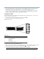
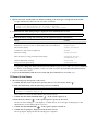
Sun SPARC® Enterprise M3000 Server
Getting Started Guide
This guide describes the minimum steps you must perform to power on and boot your server for the first time.
Before installing the Sun SPARC Enterprise M3000 server, check for late breaking information about patches and
known issues. Information found in the Sun SPARC Enterprise M3000 Server Product Notes supersedes the
information in this documents.
Detailed installation information can be found in the Sun SPARC Enterprise M3000 Server Installation Guide, which
is available at the Sun documentation web site:
http://docs.sun.com/app/docs/prod/servers.entry#hic
Safety and Compliance Information
Before performing an installation, refer to the following documents for safety information regarding the Sun
SPARC Enterprise M3000 Server:
■
Important Safety Information for Sun Hardware Systems (816-7190) – Printed document included in the ship kit.
■
Sun SPARC Enterprise M3000 Server Safety and Compliance Manual (820-5582) – Available online at the Sun
documentation web site.
Prepare the Site for Installation
1. Verify power, air conditioning, and floor area requirements.
See the Sun SPARC Enterprise M3000 Server Site Planning Guide.
2. Check the delivered items against the “LIST OF ATTACHMENT” that came with the server.
Register the System
1. Locate the serial number for your system or the customer information sheet that came with the system.
2. Go to the following web site to register your system:
http://www.sun.com/service/warranty/index.xml#reg
Install Optional Components
Before installing the server into the rack, you must first install any optional components that you ordered with
the server, such as DIMMs, PCIe cards, and so on. Refer to the Sun SPARC Enterprise M3000 Server Service Manual
for the instructions on installing optional components.
Mount the System In a Rack
For rackmounting instructions, refer to the instructions in the Sun SPARC Enterprise Rack Mounting Guide (online)
and the Rail Kit Instructions which ships with the rails.
Installation Steps for SPARC Enterprise M3000 Server
For quick installation and configuration, follow these steps. For more detailed information, see the SPARC
Enterprise M3000 Server Installation Guide.
Caution – Make sure that the AC power source circuit breaker is in the OFF position before
plugging in the AC power cables.
▼ Connecting the Cables
1. Connect the power cables to the power supply units on the rear panel of the server.
2. Connect the power cables to AC power supply system.
This server is shipped with grounding-type (three-wire) power cables. Always connect the power cables into
grounded power outlets.
FIGURE 1
Rear Panel of the Server
1
2
3
4
5
Figure Legend
Location Number
Component
1
Power supply unit
2
PCIe slot
3
Serial port (for XSCF)
4
LAN port (for XSCF)
5
Gigabit Ethernet (GbE) port (for OS)
3. Use the brown RS232C cable (serial cable, RJ-45 to DB-9) supplied with the server, and connect the
administration console to the serial port (see FIGURE 1, #3) on the rear panel of the server.
You can use any of the following devices with a DB-9 serial port as the administration console: ASCII
terminal, workstation, terminal server (or a patch panel connected to a terminal server), or personal
computer. A Serial-to-USB port adapter may be required for laptops.
▼ Initialize the XSCF
The following steps will log in to the XSCF Shell and initialize the XSCF settings. XSCF is a system control
facility to set up and control the server.
1. Set the mode switch on the operator panel to the Service mode (
).
The key for the operator panel is supplied with the server.
FIGURE 2
Operator Panel
1
2
3
4
5
Figure Legend
Location No.
Name
1
POWER LED
2
XSCF STANDBY LED
3
CHECK LED
4
Power button
5
Mode switch (Key switch)
2. Turn the AC power source circuit breaker to "ON".
After AC power is turned on, the server starts the XSCF initialization that can take up to 5 or more minutes.
When the initialization completes, the XSCF STANDBY LED (
) on the operator panel lights.
3. After the XSCF initialization completes, enter default at the login prompt.
login: default
4. Operate the mode switch within one minute according to the messages to change the mode switch.
A login authentication timeout will occur after one minute.
Change the panel mode switch to Locked and press return...
Leave it in that position for at least 5 seconds.
Change the panel mode switch to Service, and press return...
5. Confirm that the XSCF Shell prompt is displayed on the administration console.
XSCF>
6. Initialize the XSCF settings. The following are the required settings for installation.
Settings
Command
Registration of an XSCF user account, password, and user privileges
Registration of an user account of a field engineer (FE) (for maintenance)
adduser, password,
setprivileges
Date and time settings
setdate, settimezone
Confirmation of the XSCF host public key
showssh
SSH/telnet settings
setssh, settelnet
Network interface, routing, and DNS-related settings
setnetwork,setroute,
setnameserver etc.
Altitude administration setting
setaltitude
Dual power feed option setting
setdualpowerfeed
To apply the settings, the XSCF unit must be reset with the applynetwork and rebootxscf commands.
For details on the setting procedure, see the Sun SPARC Enterprise M3000/M4000/M5000/M8000/M9000
Servers XSCF User’s Guide.
7. Log in to the XSCF Shell with the user account and password that were set in the Step 6.
▼ Power On the Server
1. The following steps will power on the server.
a. Confirm that the mode switch on the operator panel is set to the Service mode (
).
b. From the XSCF Shell, enter the following console command:
XSCF> console -d 0
Connect to DomainID 0?[y|n] :y
This switches you from the XSCF Shell to the domain console.
c. Confirm that the XSCF STANDBY LED (
) on the operator panel is on.
d. Push the Power button (
) on the operator panel to power on the server.
The server starts and begins a self-diagnosis. Confirm that no error messages are displayed on the
administration console during the boot process.
e. Confirm that the POWER LED (
) on the operator panel is turned on.
f. Confirm that ok prompt is displayed on the domain console.
The ok prompt is displayed after the self-diagnosis completes.
g. Press the Enter key, and then press the "#" and “.”(period) keys.
This switches you from the domain console to the XSCF Shell.
h. From the XSCF Shell, execute the fmdump command or showlogs command, and confirm that no errors
are found.
2. Connect the system control network to a LAN port (see FIGURE 1, #4) on the rear panel of the server with
an Ethernet cable.
3. Verify the hardware configuration by using the following commands on the administration console
connected to the system control network.
Command
Prompt
Description
showhardconf
XSCF Shell
All the components installed in the server and their statuses are displayed.
Confirm that no asterisk (*) is displayed in front of any FRUs.
showhardconf -u
XSCF Shell
Check the number of FRUs mounted on the server against the “PRODUCT
TEST RECORD“ that came with the server.
probe-scsi-all
ok Prompt
Confirm that the CD-RW/DVD-RW drive unit and hard disk drive
installed in the server are recognized.
show-devs
ok Prompt
Confirm that each installed PCIe card is recognized.
To switch from the XSCF console to the ok prompt, enter the console -d 0 command. To switch from the
ok prompt to the XSCF console, press the enter key, and then press the "#" and "." (period) keys.
4. Install additional hardware or peripheral devices. If not needed, proceed to the Step 5.
For details on how to add optional devices, such as additional memory or an additional PCIe card, see the
Sun SPARC Enterprise M3000 Servers Service Manual. To add an additional storage device or other peripheral
device, see the manual supplied with the device.
5. The following steps will connect the domain to the user network. If you isolate the domain from the
network, proceed to the Step 1.
The user network is a network which enables users to access the domain.
a. Connect one end of an Ethernet cable to a GbE port (for the OS) (see FIGURE 1, #5) on the rear panel of
the server.
You can connect the Ethernet cable to a GbE port (for the OS) or to the LAN port on a LAN card mounted
in a PCIe slot (see FIGURE 1, #2).
b. Connect the other end of the Ethernet cable to the customer’s network environment.
▼ Boot the Solaris Operating System
1. The following steps will boot the SolarisTM Operating System.
The Solaris OS is preinstalled in the slot 0 of the hard disk drives.
a. From the ok prompt of the domain console, execute the boot command.
ok boot
b. After the login prompt is displayed, log in with root account.
2. Confirm the status of hardware operations and device connection by using SunVTS.
For details, see the SunVTS User’s Guide.
3. Make the initial settings for the domain.
For details, see the Sun SPARC Enterprise M3000/M4000/M5000/M8000/M9000 Servers Administration Guide.
Sun SPARC Enterprise M3000 Server Related Documentation
System Planning and Site Preparation
• Sun SPARC Enterprise M3000 Server Overview Guide
• Sun SPARC Enterprise M3000 Server Site Planning Guide
System Installation
• Sun SPARC Enterprise Equipment Rack Mounting Guide
• Sun SPARC Enterprise M3000 Server Installation Guide
Administration
• Sun SPARC Enterprise
• Sun SPARC Enterprise
Administration Guide
• Sun SPARC Enterprise
User’s Guide
• Sun SPARC Enterprise
Reference Manual
Repair and Troubleshooting
M3000 Server Product Notes
M3000/M4000/M5000/M8000/M9000 Servers
M3000/M4000/M5000/M8000/M9000 Servers XSCF
M3000/M4000/M5000/M8000/M9000 Servers XSCF
• Sun SPARC Enterprise M3000 Server Service Manual
Sun Contact Information
Topic
URL
Technical support
http://www.sun.com/service/contacting
Submitting comments on this document
http://www.sun.com/hwdocs/feedback
Patch and firmware updates
http://www.sun.com/support/index.jsp
Copyright 2008 Sun Microsystems, Inc. All rights reserved.
Copyright 2008 Sun Microsystems, Inc. Tous droits réservés.
Sun Microsystems, Inc.
www.sun.com
Manual Code C120-E549-01EN
Part No. 820-5581-10, Rev. A
October 2008
FUJITSU LIMITED provided technical input and review on portions of this material.
Entrée et revue tecnical fournies par FUJITSU LIMITED sur des parties de ce matériel.