1
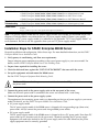
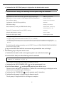
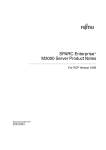
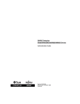
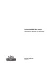
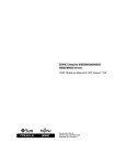
SPARC Enterprise M3000 Server
Getting Started Guide
Accessing Important Information and Documentation
Before you deploy the SPARC Enterprise M3000 server, check for late breaking information about patches for
firmware and software, and known issues. This information, found in the SPARC Enterprise M3000/M4000/M5000/
M8000/M9000 Servers Product Notes, supersedes the information in other documents. The latest version of SPARC
Enterprise M3000/M4000/M5000/M8000/M9000 Servers Product Notes, SPARC Enterprise M3000 Server Installation Guide,
and other documentation for the M3000 server are available on the following website:
http://www.fujitsu.com/sparcenterprise/manual/
SPARC Enterprise M3000 Server Documentation
System
Planning and
Site Preparation
System
Installation
•
•
•
•
•
•
•
•
•
•
SPARC Enterprise M3000 Server Overview Guide
SPARC Enterprise M3000 Server Site Planning Guide
SPARC Enterprise Equipment Rack Mounting Guide
SPARC Enterprise M3000/M4000/M5000/M8000/M9000 Servers Product Notes
SPARC Enterprise M3000/M4000/M5000/M8000/M9000 Servers Important Legal and Safety
Information (Printed)
SPARC Enterprise M3000 Server Safety and Compliance Guide
SPARC Enterprise M3000 Server Getting Started Guide (This document)
SPARC Enterprise M3000 Server Installation Guide
SPARC Enterprise M3000/M4000/M5000/M8000/M9000 Servers Administration Guide
SPARC Enterprise M3000/M4000/M5000/M8000/M9000 Servers XSCF User’s Guide
1
Administration
Repair and
Troubleshooting
Globalization
•
•
•
•
•
•
SPARC
SPARC
SPARC
SPARC
SPARC
SPARC
Enterprise
Enterprise
Enterprise
Enterprise
Enterprise
Enterprise
M3000/M4000/M5000/M8000/M9000
M3000/M4000/M5000/M8000/M9000
M3000/M4000/M5000/M8000/M9000
M3000/M4000/M5000/M8000/M9000
M3000 Server Service Manual
M3000/M4000/M5000/M8000/M9000
Servers
Servers
Servers
Servers
Product Notes
Administration Guide
XSCF User’s Guide
XSCF Reference Manual
Servers Administration Guide
For SPARC Enterprise M3000 server, the documents of localized versions will be offered on the
website:
http://www.fujitsu.com/sparcenterprise/manual/
Note – AC power supply model and DC power supply model are available for the M3000 server. The
chapters of each document are written based on AC power supply model. If there is any specific
information on DC power supply model, it is indicated in the appendix “DC Power Supply Model“ of
each document. Be sure to see the appendix when you use DC power supply model.
Installation Steps for SPARC Enterprise M3000 Server
For quick installation and configuration, follow these steps. For more detailed information, see the SPARC
Enterprise M3000 Server Installation Guide.
1. Verify power, air conditioning, and floor area requirements.
Prepare adequate power equipment according to the type of power supply to your server model. For
details, see the SPARC Enterprise M3000 Server Site Planning Guide.
2. Prepare items required for installing the server.
3. Check the delivered items against the “LIST OF ATTACHMENT” that came with the server.
4. Set up the equipment rack and mount the M3000 server.
See the SPARC Enterprise Equipment Rack Mounting Guide.
Caution – Make sure that the power source circuit breaker is in the OFF position before connecting
the power cords.
5. Connect the power cords to the power supply units on the rear panel of the server.
Make sure that each power cord is connected to the server and secured with a cord clamp.
6. Connect the power cords to the power supply system.
The requirements for connecting power cords vary depending on the type of power supply to your server
model. For details, see the SPARC Enterprise M3000 Server Installation Guide.
■
AC power supply model
The AC power supply model of the M3000 server is shipped with two grounding-type (three-wire)
power cords. Always connect the power cords into grounded power outlets.
■
DC power supply model
The DC power supply model of the M3000 server is shipped with two DC power cords. Since these DC
power cords have a connector only for the server end, a terminal matching the DC power supply
equipment will need to be attached to the DC power supply end of the cord. Moreover, the power
supply equipment must be correctly grounded.
2
FIGURE 1
Rear Panel of the Server
AC Power Supply Model
1
2
3
5
DC Power Supply Model
1
4
2
3
4
5
Location Number
Component
1
Power supply unit
2
PCIe slot
3
Serial port (for XSCF)
4
LAN port (for XSCF)
5
Gigabit Ethernet (GbE) port (for OS)
7. Use the RS232C cable (serial cable, RJ-45 to DB-9) supplied with the server in the Accessory Kit, and
connect the administration console to the serial port (see FIGURE 1, #3) on the rear panel of the server.
You can use any of the following devices with a DB-9 serial port as the administration console: ASCII
terminal, workstation, terminal server (or a patch panel connected to a terminal server), personal
computer.
Caution – Be careful not to connect a LAN cable to the serial port.
3
8. The following steps will log in to the XSCF Shell and initialize the XSCF settings.
XSCF is a system control facility to set up and control the server. To initialize the XSCF settings, use the
XSCF default user account.
a. Set the mode switch on the operator panel to the Service mode (
The key for the mode switch is supplied with the server.
FIGURE 2
).
Operator Panel
1
2
3
4
5
Location Number
Name
1
POWER LED
2
XSCF STANDBY LED
3
CHECK LED
4
Power button
5
Mode switch (Key switch)
b. Turn the power source circuit breaker to "ON".
After the power is turned on, the server starts the XSCF initialization that can take up to 5 or more
minutes. When the initialization completes, the XSCF STANDBY LED (
) on the operator panel
lights.
c. After the XSCF initialization completes, enter default at the login prompt.
login: default
d. Operate the mode switch within one minute according to the messages to change the mode switch.
A login authentication timeout will occur after one minute.
Change the panel mode switch to Locked and press return...
Leave it in that position for at least 5 seconds.
Change the panel mode switch to Service, and press return...
4
e. Confirm that the XSCF Shell prompt is displayed on the administration console.
XSCF>
f. Initialize the XSCF settings. The following are the required settings for installation.
Settings
Command
Registration of an XSCF user account, password, and user privileges
Registration of a user account of a field engineer (FE) (for maintenance)
adduser, password,
setprivileges
Date and time settings
setdate, settimezone
Confirmation of the XSCF host public key
showssh
SSH/telnet settings
setssh, settelnet
Network interface, routing, and DNS-related settings
*
setnetwork,setroute,
setnameserver etc.
Domain-SP Communication Protocol (DSCP) settings †
Altitude administration setting
setdscp
‡
setaltitude
Dual power feed option setting
setdualpowerfeed
* To apply the settings, the XSCF unit must be reset with the applynetwork and rebootxscf commands.
† To apply the settings, the XSCF unit must be reset with the rebootxscf commands.
‡ To apply changes made with the setdualpowerfeed command, power to the server must be completely disconnected and then
reconnected (all power cords must be disconnected and then reconnected). Wait at least 30 seconds before reconnecting the power cords to
the server.
For details on the setting procedure, see the SPARC Enterprise M3000/M4000/M5000/M8000/M9000
Servers XSCF User’s Guide.
g. Log in to the XSCF Shell with the user account and password that were set in Step f.
9. The following steps will power on the server.
a. Confirm that the mode switch on the operator panel is set to the Service mode (
).
b. From the XSCF Shell, enter the following console command:
XSCF> console -d 0
Connect to DomainID 0?[y|n] :y
This switches you from the XSCF Shell to the domain console.
c. Confirm that the XSCF STANDBY LED (
) on the operator panel is on.
d. Push the Power button (
) on the operator panel to power on the server.
The server starts and begins a self-diagnosis. Confirm that no error messages are displayed on the
administration console during the boot process.
e. Confirm that the POWER LED (
) on the operator panel is turned on.
f. Confirm that ok prompt is displayed on the domain console.
The ok prompt is displayed after the self-diagnosis completes.
5
g. Press the Enter key, and then press the "#" and “.“(period) keys.
This switches you from the domain console to the XSCF Shell.
h. From the XSCF Shell, execute the fmdump command or showlogs command, and confirm that no
errors are found.
10. Connect the system control network to a LAN port (see FIGURE 1, #4) on the rear panel of the server with
an Ethernet cable.
The system control network is a network that connects the XSCF to the administration console for the
system administrator's use. This connection will replace the temporary connection between the
administration console and the serial port.
The LAN ports conform to IEEE 802.3i and IEEE 802.3u. However, only the auto-negotiation mode can be
used for negotiation. The fixed mode cannot be used.
11. Verify the hardware configuration by using the following commands on the administration console
connected to the system control network.
Command
Prompt
Description
showhardconf
XSCF Shell
All the components installed in the server and their statuses are displayed.
Confirm that no asterisk (*) is displayed in front of any FRUs.
showhardconf -u
XSCF Shell
Check the number of FRUs mounted on the server against the “PRODUCT
TEST RECORD“ that came with the server.
probe-scsi-all
ok Prompt
Confirm that the CD-RW/DVD-RW drive unit and hard disk drive
installed in the server are recognized.
show-devs
ok Prompt
Confirm that each installed PCIe card is recognized.
To switch from the XSCF console to the ok prompt, enter the console -d 0 command. To switch from
the ok prompt to the XSCF console, press the enter key, and then press the "#" and "." (period) keys.
12. Install additional hardware or peripheral devices. If not needed, proceed to the Step 13.
For details on how to add optional devices, such as additional memory or an additional PCIe card, see the
SPARC Enterprise M3000 Server Service Manual. To add an additional storage device or other peripheral
device, see the manual supplied with the device.
13. The following steps will connect the domain to the user network. If you isolate the domain from the
network, proceed to the Step 14.
The user network is a network which enables users to access the domain.
a. Connect one end of an Ethernet cable to a GbE port (for the OS) (see FIGURE 1, #5) on the rear panel
of the server.
You can connect the Ethernet cable to a GbE port (for the OS) or to the LAN port on a LAN card
mounted in a PCIe slot (see FIGURE 1, #2).
b. Connect the other end of the Ethernet cable to the customer’s network environment.
6
14. The following steps will boot the Oracle Solaris Operating System.
The Oracle Solaris OS is preinstalled in the slot 0 of the hard disk drives.
a. From the ok prompt of the domain console, execute the boot command.
ok boot
b. After the login prompt is displayed, log in with root account.
15. Confirm hardware operations and device connection statuses by using the Oracle VTS software.
The Oracle VTS software is included in the Oracle Solaris OS. For details, see the Oracle VTS User’s Guide.
16. Make the initial settings for the domain.
For details, see the SPARC Enterprise M3000/M4000/M5000/M8000/M9000 Servers Administration Guide.
7
Documentation Feedback
If you have any comments or requests regarding this document, or if you find any unclear statements in the
document, please state your points specifically on the form at the following website:
http://www.fujitsu.com/global/contact/computing/sparce_index.html
Copyright ® 2007, 2012, Fujitsu Limited. All rights reserved. Oracle and/or its affiliates provided technical input and review on portions of this material.
Copyright ® 2007, 2012, Fujitsu Limited. Tous droits réservés. Entrée et revue tecnical fournies par Oracle et/ou ses affiliés sur des parties de ce matériel.
FUJITSU LIMITED
Manual Code: C120-E536-04EN
March 2012, Revision A
8