1
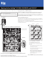
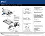
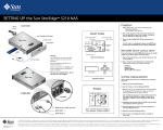
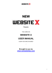
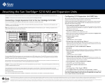
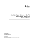
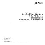
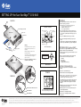
SETTING UP the Sun StorEdge 5310 NAS
TM
Power
Cord
POWERUP
CONTENTS
Follow storage installation instructions on the other side of this
poster before powering up the system.
NOTE: Always power on the units in the following order:
1. If present, expansion enclosure(s) first.
2. RAID EU controller tray next.
3. Sun StorEdge 5310 NAS last.
FRONT PANEL
Sun StorEdge 5310 NAS
Hard Drive Status LED
Power LED
Front "ears"
Front view
System Status LED
System ID LED
NIC 1 LED
Front Bezel
NIC 2 LED
System ID
Button
Power Button
Reset
Button
Set up poster
2. Power on the RAID EU controller tray power switches.
3. Turn on the Sun StorEdge 5310 NAS by pressing its power
switch.
If the IP address is automatically configured using DHCP, skip
Network Setup without DHCP and go to System Configuration.
NMI (Not Used)
Warning:
CD
1. Power on the EU-F expansion enclosure(s) (if present) power
switches and allow the hard drives to spin up for a minute. If
you do not have any EU-F expansion enclosure(s), skip to the
next step.
The X5030A slide rail kit is required to
safely mount this unit. The kit is sold
separately.
If your network does not support DHCP, follow these steps to manually
configure the IP address using the LCD Panel Controls:
Detailed installation instructions are
included with the kit.
Up
Using a kit other than the X5030A could
create a safety hazard or damage the
system or cabinet.
The front "ears" hold the bezel. Do not
use them for rack mounting.
NETWORK SETUP without DHCP
LEDs and Pushbuttons
Exit
LCD display
1. After the system has booted up, press the Select button once, then
select Set Static IP.
Select
Down
Rear view
2. Enter or accept the values listed below, then using the Select
button move the cursor to the far right to save them:
*
*
*
*
IP Address
Subnet mask
Broadcast Address
Gateway Address (if necessary)
LCD Panel Controls
SYSTEM CONFIGURATION
Using a separate system with a Java™-enabled browser connected to
the network:
1. Make sure the network link LED is green.
POWER
2. Enter the IP address of the Sun StorEdge 5310 NAS
NOTE: You must use a Java-enabled browser. If not already installed,
the Configuration Wizard prompts you to allow your browser to
install the Java plug-in from the Internet. Click Yes.
CABLING
1
POWER
A
B
2
After installing the Java plug-in, it takes about 45 seconds for the
Login page to load. Check browser settings to confirm that no
proxy server is enabled or that it is bypassed for local network
addresses.
3. Click Apply to log in (no passwords are required at this point). The
system displays the End-User agreement.
RJ45 Serial UPS Control
RJ45 NIC 1
RJ45 NIC 2
Power connector #1 powers module A
Power connector #2 powers module B
4. Click Accept Agreement to continue. The system prompts you to
start the Configuration Wizard.
5. Click Next to start the Configuration Wizard.
6. Follow the steps in the Configuration Wizard to complete the
system setup.
Copyright 2004 Sun Microsystems, Inc. All rights reserved. Use is subject to license terms. Third-party software, including font technology, is copyrighted and licensed from Sun suppliers. Portions may be derived from Berkeley BSD systems, licensed from U. of CA. Sun, Sun Microsystems, the Sun logo, Sun StorEdge, Java, and Solaris are trademarks or registered trademarks of Sun Microsystems, Inc. in
the U.S. and in other countries. All SPARC trademarks are used under license and are trademarks or registered trademarks of SPARC International, Inc. in the U.S. and in other countries. U.S. Government Rights—Commercial use. Government users are subject to the Sun Microsystems, Inc. standard license agreement and applicable provisions of the FAR and its supplements.
Part Number / Numéro de pièce:
819-1168-11 Revision A
Date: 12-2004
Copyright 2004 Sun Microsystems, Inc. Tous droits réservés. Distribué par des licences qui en restreignent l’utilisation. Le logiciel détenu par des tiers, et qui comprend la technologie relative aux polices de caractères, est protégé par un copyright et licencié par des fournisseurs de Sun. Des parties de ce produit pourront être dérivées des systèmes Berkeley BSD licenciés par l’Université de Californie. Sun,
Sun Microsystems, le logo Sun, Sun StorEdge, Java, et Solaris sont des marques de fabrique ou des marques déposées de Sun Microsystems, Inc. aux Etats-Unis et dans d’autres pays. Toutes les marques SPARC sont utilisées sous licence et sont des marques de fabrique ou des marques déposées de SPARC International, Inc. aux Etats-Unis et dans d’autres pays.
Attaching the Sun StorEdge 5310 NAS, 5300 RAID EU, and 5300 EU-F
TM
Before you can use the Sun StorEdge 5310 NAS, you must attach it to the RAID EU and the EU-Fs (if present).
Caution — • Connect all cables before powering up the systems.
• When you power off the RAID EU or EU-F, wait ten seconds before you power it back on.
• Always power up the systems in the order described on the front of this poster under "POWERUP."
Wiring for two HBA cards
Connecting the 5310 NAS to a 5300 RAID EU Controller Tray
The 5310 NAS and one 5300 RAID EU connect through a pair of Optical Fiber cables. Connect the HBA port 2 on the server to the left
module "Host 1" port on the RAID EU (1). Connect the HBA port 1 on the server to right module "Host 1" port on the RAID EU (2).
If you have two HBA cards, refer to callout A. Connect the first HBA port 2 (A1) to the left module "Host 1" port on the RAID EU. Connect
the second HBA port 2 (A2) to the right module "Host 1" port on the RAID EU. If you are connecting two 5300 RAID EUs please refer to the
Sun StorEdge 5310 NAS Hardware Installation, Configuration, and User Guide.
Connecting a Single EU-F Expansion Enclosure
The EU-F expansion enclosure connects to the RAID EU controller tray through a pair of Active Copper cables. Connect the RAID EU's left
module expansion port to "Port 1" on the left module of the EU-F (3). Connect the RAID EU's right module expansion port to "Port 2" on the
right module of the EU- F (4). If you are connecting multiple EU-Fs please refer to callout B.
A1
The RAID EU Tray Number is set to "0." Each EU-F must be set to a different number. Use the Tray Number thumb wheels to set the EU-Fs
to "1" for the first, "2" for the second, and so on.
A2
A
B
RAID EU
From HBA Port 2
From HBA Port 1
Sun StorEdge 5310 NAS connected to a 5300 RAID EU and a single EU-F Expansion Enclosure
Port 1
Port 2
Power connector #1 powers module A
2
EU-F
xxx
xxx
xxx
xxx
Host 1
2 Gb/s
B1
B2
Power connector #2 powers module B
Optional Optical NIC
1
EU-F
B3
B4
B5
B6
xxx
xxx
Host 2
xxx
Host 1
xxx
2 Gb/s
2 Gb/s
A
Host 2
xxx
xxx
2 Gb/s
EU-F
B
Expansion Ports
1Gb/s
2Gb/s
WARNING
WARNING
This unit can have more
than one power supply
cord. To de-energize the
internal circuitry you
must disconnect all
power supply cords.
This unit can have more
than one power supply
cord. To de-energize the
internal circuitry you
must disconnect all
power supply cords.
3
Conflict
X10
X1
Apparaten skal anslutas til jordat
utag nar den ansluts til ett netverk
4
Apparaten skal anslutas til jordat
utag nar den ansluts til ett netverk
Tray Number
Connecting Multiple EU-F Expansion Enclosures
xxx
A
xxx
Connect the RAID EU's left module right expansion port to "Port 1"
on the left module of the top EU-F (B1).
B
1Gb/s
2Gb/s
To EU-F
WARNING
WARNING
This unit can have more
than one power supply
cord. To de-energize the
internal circuitry you
must disconnect all
power supply cords.
This unit can have more
than one power supply
cord. To de-energize the
internal circuitry you
must disconnect all
power supply cords.
Conflict
X10
Each EU-F Expansion Enclosure is connected through a pair of Active
Copper cables.
X1
Apparaten skal anslutas til jordat
utag nar den ansluts til ett netverk
Apparaten skal anslutas til jordat
utag nar den ansluts til ett netverk
Tray Number
Units should be rack-mounted from the bottom up, starting with any EU-F(s), then the RAID EU, then the NAS.
For product documentation for the Sun StorEdge 5310, please go to
http://www.sun.com/products-n-solutions/hardware/docs/Network_Storage_Solutions/storage_appliances/index.html
Connect the RAID EU's right module right expansion port to "Port 2"
on the right module of the bottom EU-F (B2).
Each EU-F connects to the EU-F below it: the left module "Port 2"
connects to the next EU-F left module "Port 1" (B3), (B5), and so
on. The right module "Port 2" connects to the next EU-F right
module "Port 1" (B4), (B6), and so on.
Refer to the "POWERUP" instructions on the other side of this poster.