1
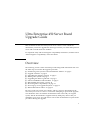
Ultra Enterprise™ 450 Server
Board Upgrade Guide
Sun Microsystems, Inc.
901 San Antonio Road
Palo Alto, CA 94303-4900 USA
650 960-1300
Fax 650 969-9131
Part No. 805-6599-11
June 1999, Revision A
Send comments about this document to: [email protected]
Copyright 1999 Sun Microsystems, Inc., 901 San Antonio Road • Palo Alto, CA 94303 USA. All rights reserved.
This product or document is protected by copyright and distributed under licenses restricting its use, copying, distribution, and
decompilation. No part of this product or document may be reproduced in any form by any means without prior written authorization
of Sun and its licensors, if any. Third-party software, including font technology, is copyrighted and licensed from Sun suppliers.
Parts of the product may be derived from Berkeley BSD systems, licensed from the University of California. UNIX is a registered trademark in
the U.S. and other countries, exclusively licensed through X/Open Company, Ltd.
Sun, Sun Microsystems, the Sun logo, AnswerBook, ShowMe How, SunCD, Ultra Enterprise and Solaris are trademarks, registered trademarks,
or service marks of Sun Microsystems, Inc. in the U.S. and other countries. All SPARC trademarks are used under license and are trademarks or
registered trademarks of SPARC International, Inc. in the U.S. and other countries. Products bearing SPARC trademarks are based upon an
architecture developed by Sun Microsystems, Inc.
The OPEN LOOK and Sun™ Graphical User Interface was developed by Sun Microsystems, Inc. for its users and licensees. Sun acknowledges
the pioneering efforts of Xerox in researching and developing the concept of visual or graphical user interfaces for the computer industry. Sun
holds a non-exclusive license from Xerox to the Xerox Graphical User Interface, which license also covers Sun’s licensees who implement OPEN
LOOK GUIs and otherwise comply with Sun’s written license agreements.
RESTRICTED RIGHTS: Use, duplication, or disclosure by the U.S. Government is subject to restrictions of FAR 52.227-14(g)(2)(6/87) and
FAR 52.227-19(6/87), or DFAR 252.227-7015(b)(6/95) and DFAR 227.7202-3(a).
DOCUMENTATION IS PROVIDED “AS IS” AND ALL EXPRESS OR IMPLIED CONDITIONS, REPRESENTATIONS AND WARRANTIES,
INCLUDING ANY IMPLIED WARRANTY OF MERCHANTABILITY, FITNESS FOR A PARTICULAR PURPOSE OR NONINFRINGEMENT, ARE DISCLAIMED, EXCEPT TO THE EXTENT THAT SUCH DISCLAIMERS ARE HELD TO BE LEGALLY INVALID.
Copyright 1999 SunMicrosystems, Inc., 901 San Antonio Road • Palo Alto, CA 94303 Etats-Unis. Tous droits réservés.
Ce produit ou document est protégé par un copyright et distribué avec des licences qui en restreignent l’utilisation, la copie, la distribution, et la
décompilation. Aucune partie de ce produit ou document ne peut être reproduite sous aucune forme, par quelque moyen que ce soit, sans
l’autorisation préalable et écrite de Sun et de ses bailleurs de licence, s’il y en a. Le logiciel détenu par des tiers, et qui comprend la technologie
relative aux polices de caractères, est protégé par un copyright et licencié par des fournisseurs de Sun.
Des parties de ce produit pourront être dérivées des systèmes Berkeley BSD licenciés par l’Université de Californie. UNIX est une marque
déposée aux Etats-Unis et dans d’autres pays et licenciée exclusivement par X/Open Company, Ltd.
Sun, Sun Microsystems, le logo Sun, AnswerBook, ShowMe How, SunCD, Ultra Enterprise et Solaris sont des marques de fabrique ou des
marques déposées, ou marques de service, de Sun Microsystems, Inc. aux Etats-Unis et dans d’autres pays. Toutes les marques SPARC sont
utilisées sous licence et sont des marques de fabrique ou des marques déposées de SPARC International, Inc. aux Etats-Unis et dans d’autres
pays. Les produits portant les marques SPARC sont basés sur une architecture développée par Sun Microsystems, Inc.
L’interface d’utilisation graphique OPEN LOOK et Sun™ a été développée par Sun Microsystems, Inc. pour ses utilisateurs et licenciés. Sun
reconnaît les efforts de pionniers de Xerox pour la recherche et le développement du concept des interfaces d’utilisation visuelle ou graphique
pour l’industrie de l’informatique. Sun détient une licence non exclusive de Xerox sur l’interface d’utilisation graphique Xerox, cette licence
couvrant également les licenciés de Sun qui mettent en place l’interface d’utilisation graphique OPEN LOOK et qui en outre se conforment aux
licences écrites de Sun.
CETTE PUBLICATION EST FOURNIE "EN L’ETAT" ET AUCUNE GARANTIE, EXPRESSE OU IMPLICITE, N’EST ACCORDEE, Y
COMPRIS DES GARANTIES CONCERNANT LA VALEUR MARCHANDE, L’APTITUDE DE LA PUBLICATION A REPONDRE A UNE
UTILISATION PARTICULIERE, OU LE FAIT QU’ELLE NE SOIT PAS CONTREFAISANTE DE PRODUIT DE TIERS. CE DENI DE
GARANTIE NE S’APPLIQUERAIT PAS, DANS LA MESURE OU IL SERAIT TENU JURIDIQUEMENT NUL ET NON AVENU.
Please
Recycle
Contents
Preface
1.
v
Ultra Enterprise 450 Server Board Upgrade Guide
Overview
1
1
Transferring Your System’s hostid and Ethernet Address
Upgrade Contents
2
2
Unpacking the Shipping Cartons
Halting Your System
3
3
Upgrading the Main Logic Board
5
Removing the Old Main Logic Board
Main Logic Board Jumpers
5
Installing the New Main Logic Board
About UltraSPARC II CPU Modules
Installing the CPU Module
5
6
8
9
Installing the Remaining Main Logic Board Components
Reassembling the System
10
Electromagnetic Compatibility
Class A EMC Label
10
12
12
Contents
iii
Information for Systems Used in Taiwan
14
14
Powering Up Your Upgraded System
Return Material Procedure
iv
16
Ultra Enterprise 450 Server Board Upgrade Guide • June 1999
15
Preface
The Ultra Enterprise 450 Server Board Upgrade Guide, used with the Ultra
Enterprise 450 Server Owner’s Guide, gives you the information you need to perform a
main logic board upgrade to your Ultra Enterprise™ 450 server.
Features and options, installation, troubleshooting, parts replacement, network
administration information, and other topics about the Ultra Enterprise 450 server
are all covered in the Ultra Enterprise 450 Server Owner’s Guide, which accompanied
your purchase of the server. Refer to the original documentation to install the parts
you will be transferring from your old server into your new Ultra Enterprise 450
server. You should also use the documentation to install any options that you
purchased with this upgrade.
In addition, you can also view many of the component installation and replacement
procedures in the multimedia CD-ROM application ShowMe How™, which also
accompanied your purchase of the original server.
Using UNIX Commands
This document may not contain information on basic UNIX® commands and
procedures such as shutting down the system, booting the system, and
configuring devices.
See one or more of the following for such information:
■
Solaris 2.x Handbook for SMCC Peripherals
■
AnswerBook™ online documentation for the Solaris™ software environment
■
Other software documentation that you received with your system
v
Typographic Conventions
TABLE P-1
Typographic Conventions
Typeface
Meaning
Examples
AaBbCc123
The names of commands, files,
and directories; on-screen
computer output
Edit your .login file.
Use ls -a to list all files.
% You have mail.
AaBbCc123
What you type, when
contrasted with on-screen
computer output
% su
Password:
AaBbCc123
Book titles, new words or terms,
words to be emphasized
Read Chapter 6 in the User’s Guide.
These are called class options.
You must be superuser to do this.
Command-line variable; replace
with a real name or value
To delete a file, type rm filename.
Shell Prompts
TABLE P-2
vi
Shell Prompts
Shell
Prompt
C shell
machine_name%
C shell superuser
machine_name#
Bourne shell and Korn shell
$
Bourne shell and Korn shell superuser
#
Ultra Enterprise 450 Server Board Upgrade Guide • June 1999
Related Documentation
TABLE P-3
Related Documentation
Application
Title
Performing diagnostic tests
SunVTS User’s Guide
SunVTS Quick Reference Card
SunVTS Test Reference Manual
Solstice SyMON User’s Guide
System and network administration
Solaris System Administrator AnswerBook
SPARC: Installing Solaris Software
Using operating system software
Solaris User’s Guide
Miscellaneous
Solaris on Sun Hardware AnswerBook
Solaris Handbook for Sun Peripherals
SPARC Hardware Platform Guide
Sun Documentation on the Web
The docs.sun.comsm web site enables you to access Sun technical documentation
on the Web. You can browse the docs.sun.com archive or search for a specific book
title or subject at:
http://docs.sun.com
Preface
vii
Sun Welcomes Your Comments
We are interested in improving our documentation and welcome your comments
and suggestions. You can email your comments to us at:
[email protected]
Please include the part number of your document in the subject line of your email.
viii
Ultra Enterprise 450 Server Board Upgrade Guide • June 1999
Ultra Enterprise 450 Server Board
Upgrade Guide
This document and the Ultra Enterprise 450 Server Owner’s Guide contain the
information you need to upgrade the main logic board in your Ultra Enterprise 450
server and to install faster CPU modules.
For important safety and electromagnetic compatibility information, read the section
“Electromagnetic Compatibility” in this document.
Overview
The following sections of this document provide background information and cover
the main steps involved in the upgrade procedure:
■
■
■
■
■
■
■
■
■
■
“Transferring Your System’s hostid and Ethernet Address” on page 2
“Upgrade Contents” on page 2
“Unpacking the Shipping Cartons” on page 3
“Halting Your System” on page 3
“Upgrading the Main Logic Board” on page 5
“About UltraSPARC II CPU Modules” on page 8
“Reassembling the System” on page 10
“Electromagnetic Compatibility” on page 12
“Powering Up Your Upgraded System” on page 15
“Return Material Procedure” on page 16
Be sure to read each section in its entirety, and any necessary information in the
Ultra Enterprise 450 Server Owner’s Guide before attempting to perform the upgrade.
You should also have on hand the documentation that came with your original
system, and the documentation supplied with any third-party devices that you
installed in your server. You will need to refer to that documentation to perform the
procedures during this upgrade.
1
Transferring Your System’s hostid and
Ethernet Address
Because the new NVRAM module on the replacement board contains a new hostid
and a new Ethernet address, unless you transfer the NVRAM module from your old
main logic board to your replacement board, your server’s Ethernet address and
hostid number will change. This information is used by the system administrator to
identify your server in the network configuration files, and the information is also
often used for licensing application software.
If you transfer the NVRAM chip from your old main logic board to the new main
logic board, you do not have to make any changes to your server configuration files
or to your application software.
Note – If you have customized your NVRAM module with an nvramrc script,
together with any non-default settings in the NVRAM, you will need to save the
information separately, so that you may restore the information after you have
performed the upgrade.
If you do not transfer your NVRAM module, the system administrator will need to
know the new Ethernet address and hostid stored in the new NVRAM module.
Upgrade Contents
Your Ultra Enterprise 450 server main logic board upgrade includes:
■
■
■
■
■
■
■
Ultra Enterprise 450 server main logic board
Class A Electromagnetic Compatibility (EMC) label
BSMI Class A warning label (required for servers used in Taiwan only)
Wrist strap
Antistatic mat
Sun Upgrade Program Policy document
Sun Upgrades RMA letter
In addition to the main logic board upgrade, you may have ordered one or more of
the following hardware components:
2
Ultra Enterprise 450 Server Board Upgrade Guide • June 1999
■
■
■
■
Memory modules (32-megabyte or larger capacity SIMMs)
CPU module
Additional DC to DC converter(s), if necessary
New disk drives
If any item, except CPU modules, is not included in the list above, you are expected
to transfer the item(s) from your old system main logic board to your new one.
When you upgrade to an Ultra Enterprise 450 server, you must return your old main
logic board to Sun Microsystems. See “Return Material Procedure” on page 16 for
additional details.
Unpacking the Shipping Cartons
Follow these steps to unpack your main logic board:
1. Inspect the shipping cartons before opening them.
If there is evidence of damage to a carton, contact your sales representative and
arrange for an agent of the carrier to be present when you remove the equipment.
2. Unpack your new Ultra Enterprise 450 server main logic board.
3. Save the cartons and the packing material.
You will need them to return your old main logic board.
Halting Your System
Caution – You must halt the system in an orderly manner. When the operating
system or any other standalone program is up and running, do not press Stop-a to
halt the system. Abruptly aborting program execution may cause damage to data
files.
Halt your system using the following procedure:
1. Save all your work.
Consult your software documentation for instructions on ending a work session and
saving your files. If you do not save your work, you could lose it when you switch
off the power.
Ultra Enterprise 450 Server Board Upgrade Guide
3
2. Perform a complete system dump before starting the upgrade process.
See your operating system documentation if you need instructions on how
to do this.
3. Return to the operating system environment.
If you are in a windowing environment, exit from it and wait for the system prompt
to appear. See the documentation supplied with your windowing system.
Caution – If you are transferring your NVRAM module, and have customized your
NVRAM module with an nvramrc script, together with any non-default settings in
the NVRAM, you will need to save the information separately now, so that you may
restore the information after you have performed the upgrade.
4. Halt the operating system.
See the documentation supplied with your operating system for instructions on how
to halt it.
■
For Solaris 2.5.1 Hardware 11/97 or later compatible systems, type:
% su
Password: superuser password
# /usr/sbin/shutdown -y -g60 -i0
The operating system warns other users of your system of the impending shutdown,
and then halts itself after a one-minute delay. If you wish to provide a longer delay,
see the man page for shutdown(1).
The system responds with system halt messages, followed by either the > prompt or
the ok prompt. When either prompt appears, you can safely turn off the power in
the proper sequence.
5. Turn off the power in sequence to:
a. External drive units (if any)
b. Ultra Enterprise 450 server unit
c. Monitor (if applicable)
4
Ultra Enterprise 450 Server Board Upgrade Guide • June 1999
Upgrading the Main Logic Board
For the procedures that follow in this section, use the sections in the Ultra
Enterprise 450 Server Owner’s Guide. Be sure to read all the information that precedes
the steps and follow any procedures noted there in the Ultra Enterprise 450 Server
Owner’s Guide.
You should also have on hand the documentation supplied with any third-party
devices that you installed in your server’s main logic board. You will need to refer to
that documentation to perform some of the procedures during this upgrade.
The following sections cover the main steps involved in the main logic board
upgrade procedure:
■
■
■
■
■
■
“Removing the Old Main Logic Board” on page 5
“Main Logic Board Jumpers” on page 5
“Installing the New Main Logic Board” on page 6
“About UltraSPARC II CPU Modules” on page 8
“Installing the CPU Module” on page 9
“Installing the Remaining Main Logic Board Components” on page 10
Be sure to read each section in its entirety, and any necessary information in the
Ultra Enterprise 450 Server Owner’s Guide to upgrade the main logic board.
Removing the Old Main Logic Board
● Remove the old main logic board using the steps in the section “How to Remove
the Main Logic Board” in the Ultra Enterprise 450 Server Owner’s Guide.
Remove and clearly label the old NVRAM module, if you plan to transfer it to the
new main logic board.
Main Logic Board Jumpers
The following information supersedes the information presented in the
Ultra Enterprise 450 Server Owner’s Guide concerning main logic board jumpers:
■
The clock mode select jumper (J2701) is now used on the Ultra Enterprise 450
server main logic board.
Ultra Enterprise 450 Server Board Upgrade Guide
5
Set the clock mode jumper shunt at address J2701 to correspond to the speed of your
UltraSPARC II CPU module(s). Verify that the jumper setting is correct before
starting the system.
Jumper
J2701
Shunt on
Pins 1 + 2 Selects
Shunt on
Pins 2 + 3 Selects
Default Shunt1
on Pins
Signal Controlled
Correct clock
mode for
UltraSPARC II
250- and 300MHz CPU
modules
Correct clock
mode for
UltraSPARC II
400-MHz CPU
modules
1+2
UPA_RATIO2
1. Factory setting for main logic boards shipped without CPU modules installed.
Installing the New Main Logic Board
1. Install the new main logic board.
a. If you are using the new NVRAM, perform the steps in the section “How to
Install the Main Logic Board” in the Ultra Enterprise 450 Server Owner’s Guide,
and then go to the next section “About the New NVRAM Module Data” on
page 7.
b. If you are transferring the old NVRAM module, perform the first three steps in
the section “How to Install the Main Logic Board” in the Ultra Enterprise 450
Server Owner’s Guide. Then perform the following steps.
2. Disconnect the main logic board from its power connector.
Loosen the captive screws that secure the board to the system rear panel, and pull
the handles at the rear of the board until the board is fully disengaged from its
power connector.
Caution – Failure to do so could corrupt the information stored in the NVRAM
module and adversely affect operation of the system.
3. Remove the new NVRAM module from the new main logic board using the steps
in the section “How to Remove the NVRAM Module” in the Ultra Enterprise 450
Server Owner’s Guide.
Be sure to keep the old and the new NVRAM modules clearly identified. You will
need to install the new module in the old system board when you return it to Sun
Microsystems.
6
Ultra Enterprise 450 Server Board Upgrade Guide • June 1999
4. Install the old NVRAM module onto the new main logic board using the steps in
the section “How to Install the NVRAM Module” in the Ultra Enterprise 450
Server Owner’s Guide. Then perform the remaining steps below.
Note – If you have customized your NVRAM module with an nvramrc script,
together with any non-default settings in the NVRAM, you will need to restore the
information separately, after you have performed the upgrade.
5. Reconnect the main logic board to its power connector.
Push the handles at the rear of the board until the board is fully engaged in its
power connector. Tighten the captive screws that secure the board to the system rear
panel.
6. Follow the remaining steps in the section “How to Install the Main Logic Board”
in the Ultra Enterprise 450 Server Owner’s Guide, and then go to the section
“About UltraSPARC II CPU Modules” on page 8.
About the New NVRAM Module Data
The hostid and Ethernet address are stored in the NVRAM module on the main logic
board.
Locate the NVRAM module on the main logic board. If necessary, see the section
“How to Remove the NVRAM Module” in the Ultra Enterprise 450 Server Owner’s
Guide.
The system’s new Ethernet address is on the label on the new NVRAM module. The
label contains part of the system’s Ethernet address, a six-digit hexadecimal number.
For example, the NVRAM label numbers might read 79F843. These numbers
comprise the last three pairs of numbers in the system’s Ethernet address. The
system’s Ethernet address is the label number with a prefix of the numbers 080020.
Thus the system’s new Ethernet address in this example would be 08:00:20:79:F8:43.
The system’s new hostid is on the label on the new the NVRAM module. The label
contains part of the system’s hostid, a six-digit hexadecimal number.
For example, the NVRAM label numbers might read 79F843. The system’s hostid is
the hexadecimal number with a prefix of the number 80. Thus the system’s new
hostid in this example would be 8079F843.
Note – The system’s Ethernet address and hostid are also displayed at
power up on the system banner.
Ultra Enterprise 450 Server Board Upgrade Guide
7
About UltraSPARC II CPU Modules
The Ultra Enterprise 450 server supports up to four 400-MHz UltraSPARC™ II CPU
modules, each with 4 Mbytes of integrated cache memory. The following figure
shows the new unshrouded 400-MHz UltraSPARC II CPU module.
Identifying CPU Modules
Before installing a CPU module, verify that the module is one of the following
UltraSPARC II modules for Ultra Enterprise 450 server systems. The following table
identifies CPU module speeds.
Module Speed (MHz)
Part Number
250 MHz
501-4857 or 501-4278
300 MHz
501-4849 or 501-4196
400 MHz
501-5239 or 501-5446
Note – If the CPU module you are installing has a part number of 501-5239-04 or
higher, you will need to apply a Class A EMC label to your Ultra Enterprise 450
server. Follow the instructions under “Class A EMC Label” on page 12.
8
Ultra Enterprise 450 Server Board Upgrade Guide • June 1999
CPU Module Configuration Rules
Before configuring your CPU modules, to determine if your new system will
support the power requirements of the new configuration, review the section
“System Power Requirements Worksheet” on page 9 of this guide, and see the
section “How to Determine System Power Requirements” in the Ultra Enterprise 450
Server Owner’s Guide.
If you need to know your system’s power consumption, see the section “How to
Determine System Power Requirements” in the Ultra Enterprise 450 Server Owner’s
Guide to determine if your new system will support the power requirements of the
new configuration.
Configure your UltraSPARC II CPU modules in your server according to the rules in
the section “About CPU Modules” in your Ultra Enterprise 450 Server Owner’s Guide.
System Power Requirements Worksheet
The following information is an addition to the section “System Power
Requirements Worksheet” in the Ultra Enterprise 450 Server Owner’s Guide. If you are
calculating your power needs for systems that will include one or more 400-MHz
CPU modules and the SunCD™ 32 CD-ROM, you will need the following
information for your calculations.
Line
No.
Option
Qty
+3.3
VDC
Amps
Total
Amps @
3.3 V
+5 VDC
Amps
Total
Amps @
5V
+12
VDC
Amps
Total
Amps @
12 V
CPU Options
400 MHz CPU with
4 MB Ecache and DC/DC
converter
5.0
5.6
Internal Storage Device Options
SunCD 32 CD-ROM
0.55
0.61
Installing the CPU Module
Caution – Before you install any CPU module in your new main logic board, read
the section “Main Logic Board Jumpers” on page 5, and verify that the jumper
setting on the new main logic board is correct for the speed of the CPU module you
are installing. Serious system damage can result if your main logic board clock mode
jumper is set incorrectly.
Ultra Enterprise 450 Server Board Upgrade Guide
9
● Install each CPU module using the steps in the section “How to Install a CPU
Module” in the Ultra Enterprise 450 Server Owner’s Guide.
Caution – All CPUs installed in a system must operate at identical clock speeds.
Note – Before you install the fourth CPU module in the top CPU slot (CPU-A1),
remove the blank baffle installed in the connector (J0101). Grasp the blank baffle by
the front handle and slide it out of the CPU slot.
Keep the blank baffle. If you ever remove a CPU module from the top CPU slot
(CPU-A1), re-install the blank baffle in the connector (J0101).
Installing the Remaining Main Logic
Board Components
Refer to the following sections in the Ultra Enterprise 450 Server Owner’s Guide to
restore the remaining main logic board components you removed from the main
logic board.
1. Install any PCI cards using the steps in the section “How to Install a PCI Card.”
2. Install any DC/DC converter using the steps in the section “How to Install a
DC/DC Converter.”
3. Install any memory module using the steps in the section “How to Install a
Memory Module.”
Note – If you purchased new memory modules, be sure to consult the configuration
rules in the section “About Memory” in the Ultra Enterprise 450 Server Owner’s Guide.
Reassembling the System
Refer to the following sections in the Ultra Enterprise 450 Server Owner’s Guide to
reassemble the system.
1. Install the CPU fan tray using the steps in the section “How to Install the CPU
Fan Tray Assembly.”
10
Ultra Enterprise 450 Server Board Upgrade Guide • June 1999
2. Reconnect any other devices that you disassembled from the main logic board to
perform the upgrade.
Consult the documentation that accompanied these devices for details about
installing and configuring them.
3. Remove the right side panel using the steps in the section “How to Remove the
Right Side Panel.”
Examine the chassis bar code label on the top of the system (see figure below). On
the bottom line is a number. Write down the number. If your number is the same, or
lower than 5402833-04, you must apply a Class A EMC label to your Ultra Enterprise
450 server.
Chassis bar code label
4. Install the right side panel using the steps in the section “How to Install the Right
Side Panel.”
5. Install the left side panel using the steps in the section “How to Install the Left
Side Panel.”
6. Reconnect any external cables to the rear panel of the main logic board; see the
section “Locating Rear Panel Features.”
Ultra Enterprise 450 Server Board Upgrade Guide
11
Electromagnetic Compatibility
If either of the following scenarios are true for your system, you must read the
section “Class A EMC Label” and apply onto the server the Class A EMC label
included in your upgrade kit.
■
The number you recorded in Step 3 in the section “Reassembling the System” is
the same or lower than 5402833-04.
■
The CPU module you are installing has a part number of 501-5239-04 or higher.
If the chassis number you recorded in Step 3 in the section “Reassembling the
System” is higher than 5402833-04 and the CPU module you are installing has a part
number of 501-5239-03 or lower, your Ultra Enterprise 450 server system meets
Class B requirements for electromagnetic interference (EMI) conforming to
international standards. Read the following paragraphs, and then skip forward to
the section “Powering Up Your Upgraded System” on page 15.
Some of the Class B standards are noted in the “Declaration of Conformity” in the
“Regulatory Compliance Statements” at the beginning of the Ultra Enterprise 450
Server Owner’s Guide. The Class B requirements are intended for home use, and are
more stringent than Class A requirements. The Class B limits are designed to
provide reasonable protection in the home against radio frequency interference.
Caution – Connecting headphones to the headphone jack of the Ultra Enterprise
450 CD-ROM drive can result in radio frequency emissions that exceed Class B
limits. Please read the sections that apply to Class A equipment in the “Regulatory
Compliance Statements” at the beginning of the Ultra Enterprise 450 Server Owner’s
Guide. There are several measures you can take to correct interference problems. For
additional correction details, see the FCC Class B Notice in the “Regulatory
Compliance Statements in the Ultra Enterprise 450 Server Owner’s Guide.
Class A EMC Label
Any Ultra Enterprise 450 server configured with a chassis numbered 5402833-04 or
lower, with an upgraded main logic board or with new 400-MHz, 4-Mbyte
UltraSPARC II CPU modules with a part number of 501-5239-04 or higher, meets the
Class A system requirements for EMI, but not the Class B requirements. Please read
the sections that apply to Class A products in the “Regulatory Compliance
Statements” at the beginning of the Ultra Enterprise 450 Server Owner’s Guide.
12
Ultra Enterprise 450 Server Board Upgrade Guide • June 1999
Note – To be compliant with international EMC regulations, the upgrade label
provided must be correctly applied to the upgraded system.
Read and follow the directions in the next section.
Applying a Class A Label
1. Locate the Class B label on the rear panel of the Ultra Enterprise 450 server.
The label is located at the top of the back panel in the middle, just above the AC line
filter.
2. Peel off the new Class A label from its backing material.
3. With the sticky side down, align the left edge of the new label with the left edge
of the existing large label.
4. Position the new label so that it covers all of the old label except the right side
panel containing Electrical Ratings and Product Safety marks; and on older labels,
the country of origin in the bottom left corner. Press the label firmly into place.
c
Ultra Enterprise 450 Server Board Upgrade Guide
13
Information for Systems Used in Taiwan
If your Ultra Enterprise 450 server meets Class A requirements as defined in the
section “Electromagnetic Compatibility” on page 12, the following warning applies
to your system:
To be compliant with BSMI electromagnetic compatibility regulations, you must
apply the supplied BSMI warning label (part number 263-0719-01) onto your system
as indicated in the figure.
Ultra Enterprise 450
BSMI
263-0719-01
14
Ultra Enterprise 450 Server Board Upgrade Guide • June 1999
12
BSMI
Powering Up Your Upgraded System
The procedure for powering up your system depends on the operating system you
are using. Refer to the Ultra Enterprise 450 Server Owner’s Guide for instructions about
configuring your server. Your system is connected to a network, and the network
environment may require some advance preparation before you turn on your server.
What you, or your system administrator will have to do will also depend on
whether you decided to transfer your old NVRAM module to the new main logic
board.
If you did not transfer your old NVRAM module, be sure to inform your system
administrator of the new hostid and the new Ethernet address before you power up
the server. You, or your administrator, will need to update certain network
configuration files before your system can join the network. In addition, you may
also need to register any software licenses that use your system’s new hostid
Ultra Enterprise 450 Server Board Upgrade Guide
15
number. This information is used by the system administrator to identify your server
in the network configuration files, and the information is also often used for
licensing application software.
Do not power up your system until you have notified your system administrator
and have received permission to proceed. If you must act as your own system
administrator, see the documentation that accompanies your operating system
software.
Return Material Procedure
With your upgrade you ordered a Return Material Authorization (RMA)
documentation set that includes a letter and instructions for returning your old
equipment to Sun Microsystems.
Once you have completed the upgrade procedure, you must return your old main
logic board to Sun Microsystems. Before returning your old main logic board, be
sure to remove and keep any memory modules that you have purchased, but did not
transfer to the new main logic board.
To return your old equipment to Sun Microsystems:
1. Disconnect any cables that may still be attached to the system unit.
2. Pack the components in appropriate packing materials.
Use the main logic board’s Ultra Enterprise 450 upgrade packing materials, if
possible. Be sure that the components are secure and well padded inside their
respective shipping cartons.
3. Follow the instructions in the Sun Upgrades RMA Letter to return the equipment
to Sun Microsystems.
You have completed the upgrade procedure. If you encounter any difficulties with
your new server, call the Sun Response Center or your authorized service provider.
16
Ultra Enterprise 450 Server Board Upgrade Guide • June 1999