1
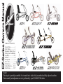
EZ-Series Owners Manual
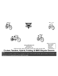
BICYCLES
BICYCLES
EST.
1971
TABLE OF CONTENTS
General Rules...................1
Night Riding.....................1
Recumbent Riding Tips...2
Fitting Your Recumbent..3
Assembly....................4-11
EZ Rider .........................12
EZ Speedster ...................13
EZ-3 USX.....................14
Maintenance.............15-19
Limited Warranty........20-21
Specifications.............22-27
Notice:
This bicycle is partially assembled. It is intended to be sold in fully assembled and fully adjusted condition.
Final assembly and adjustment are to be performed by your SUN BICYCLE dealer.
Page 1
RECUMBENT SAFETY AND RIDING TIPS
General Rules for Safe Recumbent Riding
1. Always wear a CPSC approved helmet and some form of eye protection.
2. Always ride with a rear view mirror attached to your helmet or mounted on the recumbent.
3. Obey all traffic rules and regulations, signs and signals.
4. Ride on the side of the road, going in the same direction as the traffic and in single file.
5. Use proper hand signals when turning or stopping.
6. Be alert at all times, especially watch for cars pulling out into traffic or for opening doors.
7. Inspect your Sun Recumbent before every ride. Make sure all nuts and bolts are securely tightened. Check your brakes by applying
them and rock your Sun Recumbent forward and back to make sure they are engaging properly. Check your tires for proper air pressure
as indicated on the sidewall of the tires. Make sure the quick release levers on wheels and seat are secure. Also check for any
other possible mechanical problems.
9. Do not "stunt ride" or hitch a ride on other vehicles.
10. Do not ride carelessly.
11. Use extreme caution when riding in wet, icy or otherwise hazardous conditions.
WARNING: J&B Importers, Inc. is not responsible for accidents resulting from failure to comply with all bicycling safety laws. Contact your
local authorities for more specific information about such laws.
1.
2.
3.
4.
Night Riding Tips
Your Sun Recumbent is equipped with front, rear, wheel and pedal reflectors. They should be kept clean at all times, and never be
removed from your recumbent.
Always use an appropriate lighting system when riding at night.
Ride with extreme caution. Be alert for cars, pedestrians, runners and other bicyclists. Ride defensively and watch for road hazards.
Wear light colored clothing and use reflective tape on clothing or helmets to help make you more visible at night.
WARNING: Reflectors alone are not adequate for night visibility. Use a high quality front and rear lighting system for greater visibility.
Page 2
Wet Weather Caution
When rims and brakes are wet due to muddy, wet or icy road conditions the distance needed to stop safely increases. You must, therefore,
anticipate the additional distance needed to stop in such circumstances. Reduce your speed and take corners slowly and carefully. Hard application of the brakes on wet or icy pavement (or on loose gravel or debris) can cause the wheel(s) to lock up and skid, resulting in possible
loss of control. Slowly apply brakes in a gradual, controlled manner to avoid skidding or loss of control.
Recumbent Riding Tips
There are some unique features to be aware of that will help you enjoy riding your Sun Recumbent. You may find it helpful to practice riding
in an open area, such as a paved, empty parking lot or a traffic-free road. Before riding your Sun Recumbent, please carefully read this
manual. This will enable you to familiarize yourself with the mechanical operations.
1.
2.
3.
4.
5.
6.
Relax the upper body.
Do not pull on the handlebars or tense the shoulders as this leads to over-steering the recumbent.
Ride with relaxed pressure on the handlebars.
When starting to ride, be sure the recumbent is in a low gear.
Get comfortable in the seat, and place both feet on the ground (see Seat Installation, Removal and Adjustment on page-10).
While sitting comfortably on your Sun Recumbent, with both feet on the ground, try propelling the recumbent slowly with your feet on
the ground. Like walking; left, right, left, right... while gently steering a little to the left and right. Keep walking the recumbent with your
feet until you can pick both feet up off the ground an inch and be able to balance yourself and steer comfortably. When you feel comfort
able, then you can try pedalling.
7. Stabilize the recumbent by applying the brake, put one of your feet on the pedal and back pedal until the crank is at the top in a vertical
position.
8. With firm pressure, push on the pedal; lift the other foot off the ground, as you release the brake and place the other foot on the other
pedal.
9. Lean back into the seatback and pedal confidently in an appropriate gear. Propel yourself at a safe and reasonable speed.
10. When riding on level ground or going downhill, lean back and relax. Up hill it sometimes helps to lean forward a little.
11. Before coming to a stop, gear down (while spinning the pedals in a forward motion); this will enable you to start again in a low gear.
Page 3
Recumbent Riding Tips (continued)
Your body may require some adjustment to the riding position and muscle groups used that the Sun Recumbent promotes. This is natural;
adaptation to the new position will vary, depending on individual physiology and exercise regimes.
1.
2.
3.
Take short rides on level or gently sloping terrain for a few days before attempting long distances or more aggressive riding.
Downshift and maintain a high RPM when climbing hills. Failure to do so can lead to possible knee irritation or injury.
If you feel tight or sore in some areas, you will benefit from a warm up and stretching routine before and after riding.
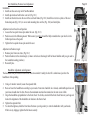
Fitting Your Sun Recumbent.
Your Sun Recumbent will accommodate most body sizes. In order to ride comfortably and safely, you
should adjust the Sun Recumbent to fit your body.
There are 3 adjustments that can be made to customize the fit of your Sun Recumbent:
a. Seat distance from the pedals
b. Seat back angle
c. Handlebar height and angle
1.
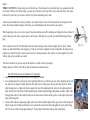
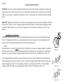
When seated, your knee should be just slightly bent when the forward foot is in the farthest position. This is adjusted by moving the seat along the length of the frame, moving you closer or
farther away from the pedals (see Seat Installation, Removal and Adjustment on page-10). For full
power, leg extension and the least stress on your knees, double check your seat to pedal position in
the following way: Try to touch the heel of your shoe to the pedal with your knee locked. You
should barely be able to reach the flat part of the pedal. Now when you put the ball of your foot on
the pedal. You should have the proper bend in your knees. (Fig. 3.1)
2.
The handlebars should be at a height that is most comfortable for your hands and arms and that allows knee clearance when pedaling.
The handlebars are adjusted by raising or lowering the stem and adjusting the angle. (see Handlebar Adjustment and Alignment page-10).
(Fig. 3.1)
ASSEMBLY
Page 4
Your Sun Recumbent is 90% assembled at the factory, therefore is easily set up in a few minutes.
Tools Needed for Assembly (Not Included)
Notice:
2, 4, 5 and 6 mm Hex wrench
15 mm open-ended wrench
This recumbent is partially assembled. It is intended
Adjustable wrench
to be sold in a fully assembled and fully adjusted
Flat blade screwdriver
condition. Final assembly and adjustment are to be
Philips head screwdriver
performed by your SUN BICYCLES dealer..
Scissors/Diagonal Cutters
1.
2.
3.
4.
Unpack Carefully as Follows:
Carefully remove the recumbent by lifting it straight out of the box. Be careful not to scratch the recumbent or
yourself on the carton staples.
Carefully remove the packing material from the frame.
Carefully clip the plastic ties that secure the handle bar and front wheel to the recumbent during shipping.
Check and make sure parts box is included.
You are now ready to begin assembly. Please read carefully the following directions.
1.
2.
3.
4.
5.
6.
7.
Handlebar and Front Wheel Installation
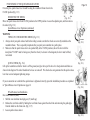
Loosen the 2 stem bolts with a 6mm hex wrench and position the stem down parallel to the handlebar. Tighten the
top stem bolt completely, then tighten the lower bolt securely (Fig. 4.1)
Apply a light coat of grease to the expander wedge.
Place the bottom end of the stem into the fork. Be sure that the minimum insertion line is not exposed. Tighten the
expander bolt with a 6mm hex wrench.
Remove the spacer from the front fork.
Open the front wheel quick-release lever. Loosen the QR nut a few turns.
Seat the wheel axle in the slot on the front fork dropouts. Make sure it is fully seated in the slot. Traditionally the
QR lever is on the left hand side from the seated position. (Fig. 4.2)
Make sure the front wheel is centered property between the fork blades.
(Fig. 4.1)
(Fig. 4.2)
Page 5
8.
9.
10.
11.
12.
13.
1.
2.
3.
4.
1.
2.
Handlebar and Front Wheel Installation (continued)
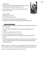
Tighten the nut and close the quick-release lever with firm pressure (see Quick Release Lever Operations on page
16, for full operation instructions).
Align the handlebars perpendicular to the front wheel by standing with the front wheel between your legs. Look at
the alignment of the handlebars in relation to the front wheel. Then fully tighten the expander bolt. (Fig. 5.1)
To check for tightness, hold the front wheel between your legs and try to turn the handlebars.
Check for proper installation of the front wheel before each ride.
Be sure the quick-release lever is in the closed position.
Lift the recumbent off the ground and hit the wheel sharply from above to confirm that it is firmly attached.
(Fig. 5.3)
(Fig. 5.1)
Front Linear Pull Brake Installation / Front and Rear Linear Pull Brake Adjustment
Place brake cable nipple firmly into nipple slot on lever. (Fig. 5.2) Pass brake inner cable through grooves into
lever bracket.
(Fig. 5.2)
Check brake pads, make sure they are aligned correctly on the rim, and there is a gap of 1mm between the top of
the rim and the top of the pad. Hold each pad against the rim (one at a time) & tighten mounting nut securely.
(Fig. 5.3)
Insert cable through cable guide pipe, cable protector and anchor-bolt. Slot cable guide pipe into holder and fit protector over guide pipe end. Set cable in anchor bolt so that combined pad rim clearance (A+B) is 2mm, then tight
en anchor bolt. (If clearance is not 1mm on each side, it will be balanced out in step 4). Crimp end cap onto cable
end. (Fig. 5.4)
(Fig. 5.4)
Balance brake arms by turning spring-tension adjusters. Depress brake lever a few times while checking to see that
tension is equal for both arms. Pad/rim contact should occur at the same time on each side. Clearance should be
1mm on each side. Don't set tension too high. (Fig. 5.5)
Notes
Spring tension adjusters require a 2mm hex wrench. All other brake bolts use a 5mm hex wrench.
Pad/rim clearance can be further adjusted by turning the brake lever-adjusting barrel. (Fig. 5.6)
Caution: Linear pull brakes must be used with linear pull brake levers. Linear pull brakes offer considerable braking
power with little leverage force, and require practice at low speeds before normal use. J&B Importers, Inc. is not
responsible for damage or injury as a result of improper use or installation.
(Fig. 5.5)
(Fig. 5.6)
SPECIAL CAUTION: Braking in wet weather conditions:
In wet weather conditions, you will need to increase the distance needed to stop safely. Anticipate the extra distance
you will need, ride slowly and carefully. Squeeze your brake levers slowly and with gradual pressure to avoid skidding
or loss of control. The same caution should be observed on loose gravel or dirt. Failure to be cautious during wet or
other severe road conditions may result in a serious accident.
1.
2.
3.
4.
Trike Rear Unit and Wheel Installation
Install loosely the two carriage bolts with their nuts and washers, to the two holes in the end of the trike frame stay.
The heads of the bolts are on the inside of the frame.
Slide the arms of assembled rear unit between rear frame stays, up to and between carriage bolt heads and frame
slot. Finger tighten nuts. (Fig 6.1)
Both wheels are the same. The hub flanges have three holes that fit the studs on the axle flange (Fig 6.2).
Install the drive wheel first, (right side). Add axle washer on the outside and tighten locking nut securely.
Now put the second wheel on left side. This wheel is the idler. First slip on the spacer (Fig 6.3), then the wheel,
followed by a washer and the locking nut until it touches the bearing. Now loosen 1/2 turn.
Do Not Over Tighten. Leave Some Side-To-Side Play (About 1 to 2mm).
Warning: Very Important: It is critical for the protection of the bearings, that you inform your customer that the idler
wheel requires a slight amount of play in order to prevent bearing damage.
5.
6.
7.
8.
5.
Thread small 50 Link chain over welded sprocket on the drive hub unit and over the fixed sprocket on the rear
axle (Fig 6.4). Connect the connecting link, make sure both sprockets are aligned. If they need alignment, loosen
set screw on fixed sprocket, re-align, make sure axle key is positioned under set screw then re-tighten set screw.
Slowly pull unit towards end of trike until chain slack is taken up.
Tighten the two forward carriage bolts. (Fig 6.1)
Turn chainwheel and see if chain runs smoothly with no binding or excessive noise. If not, loosen bolts, move unit
slightly forward. Tighten bolts and check chain function again.
If chain now runs O.K. tighten all four carriage bolts securely, taking care that the unit does not shift.
Page 6
(Fig. 6.1)
(Fig. 6.2)
(Fig. 6.3)
(Fig. 6.4)
Page 7
TRIKE CAUTIONS: A trikes widest point is behind you, if the front goes by an obstacle there is no guarantee that the
rear wheels will also clear. When riding, you must give clearance to the edge of the road or sidewalk. Stay clear of potholes and be aware that you can lose control if any wheels should drop into a hole.
A trike does not handle like a bicycle, therefore, you cannot lean into a turn. All wheels must be on the ground at all
times. Do not make sudden changes of direction, you could unbalance the trike and have an accident.
When beginning to ride, stay at a slow speed. You must acclimate yourself to handling and turning this three wheeler. If
you feel insecure, slow down, and proceed at a slower pace. With practice, you will get comfortable riding and stopping.
The rear wheels on the EZ-3SX Recumbent trike only have braking on one wheel (the right hand or “drive” wheel)
Always use both hand brakes when stopping . If only the rear brake is applied, the trike could pull to the right and you
could loose control.If the drive wheel looses traction in a turning situation, with only the rear brake applied, your trike
will not stop and you could loose control.
(Fig. 7.1)
The trike is made for one person only and the basket is not built to hold a passenger.
Weight capacity is 300 lbs. This trike is built for manual (non-motorized) use.
1.
2.
3.
Rear Disc Brake Set-up and Adjustment (if equipped)
Lightly lubricate cable fixing bolt to prevent stripping the threads.
Loosen adjusting barrel and lock nut on the right hand brake lever so that the grooves on the adjusting barrel, lock
nut, and lever are aligned. Lightly lubricate cable with clear or white grease. Secure cable end into lever. Guide
cable through grooves, tighten the lock nut against the top of the adjusting barrel and screw the adjusting barrel
fully into the lever body. Slide cable through housing. Guide housing through cable guides on frame. Guide cable
through cable anchor. Cable should be between the cable anchor washer and the groove on the caliper action arm.
Snug cable fixing bolt
Tension cable without compressing caliper action arm. Cable should be tight with no sag. Secure cable fixing bolt
tightly. Squeeze lever firmly and hold for a few seconds. Re-tension the cable and tightly secure the cable fixing
bolt. Cut excess cable leaving approximately 2" (5cm) length. Install cable end cap and crimp tightly.
(Fig. 7.2)
4.
5.
Rear Disc Brake Set-up and Adjustment (if equipped) Continued
Spin hub in forward rotating direction. Rotor should run freely between brake pads. Some drag is normal prior to
first usage. Pads will wear down gradually with normal usage. As this occurs, loosen the cable fixing bolt and
retension the cable. Secure cable fixing bolt tightly before use.
If the rotor is contacting either brake pad, try the following: 1- realigning the caliper by loosening the mounting
bolts slightly and repositioning the caliper (side to side) so the rotor is in between the brake pads. Retighten
mounting bolts. [Locking torque 60 +/-5 kg-cm] 2- Using a 2mm allen wrench, loosen the nylock screw on the
top inside of the caliper shell. Using a 5mm allen wrench, slightly turn the pad adjusting plate on the backside of
the caliper. A clockwise (right) turn will decrease the clearance of the pads. A counterclockwise (left) turn will
increase the clearance of the pads. Retighten the nylock screw. [Locking torque 10-15 kg-cm]
Note: After the first few rides, re-tension the brake cable to take up the initial cable stretch that occurs. Do not use the
brake lever adjusting barrels. This will cause the brake modulation to change, resulting in decreased braking action.
1.
2.
3.
4.
5.
6.
Disc Brake Pad Replacement
Tools required (not included):
Needle-Nose Pliers
2mm and 5mm allen wrench
Check the brake pads for wear. At 0.5mm or less, the pads are worn and must be replaced for continued safe
braking.
Remove caliper from the frame.
Using a needle-nose pliers, clamp the tab of the outside brake pad [black] and pull towards the inside pad and
down to release. Loosen the nylock screw on the caliper. Using a 5mm allen wrench, remove the pad adjusting
plate. Push the blue pad out through the back of the caliper. Dispose of the old pads properly.
Insert the outside [black] pad into the caliper and align tab with slot. Insert the new blue pad through the caliper
and align tab with slot. Replace the pad adjusting plate, threading it into the caliper until the back of the tab
contacts the back of the slot. There should be approximately 3mm of space. Tighten the nylock screw securely.
Re-install caliper onto frame. Check for proper alignment.
Retighten mounting bolts. (Locking torque 60 +/-5 kg-cm).
Adjust as needed per installation instructions (See Rear Disc Brake Adjustment page-7).
Page 8
(Fig. 8.1)
Disc Brake User Maintenance Tips
The spring load of the action arm should be fast and smooth. Be sure to inspect brake cable prior to installation for
any broken wires. Replace with a high-quality cable if necessary. Make sure cable is lubricated before it is inserted
into the housing.
The caliper floating mechanism can be checked by moving the installed caliper laterally (side to side). There
should be 2mm of play to either side. If okay, re-install wheel. If not, please consult your dealer for further service.
Page 9
1.
2.
SPECIAL CAUTION: Braking in wet weather conditions:
In wet weather conditions, you will need to increase the distance needed to stop safely. Anticipate the extra distance
you will need, ride slowly and carefully. Squeeze your brake levers slowly and with gradual pressure to avoid skidding
or loss of control. The same caution should be observed on loose gravel or dirt. Failure to be cautious during wet or
other severe road conditions may result in a serious accident.
WARNING: The rear wheels on the EZ-3SX Recumbent trike only have breaking on one wheel (the right hand or
“drive” wheel) Always use both hand brakes when stopping . If only the rear brake is applied, the trike could pull to the
right and you could loose control.If the drive wheel looses traction in a turning situation, with only the rear brake
applied, your trike will not stop and you could loose control.
Pedal Installation
The pedals are stamped "R" and "L" on the threaded end of the pedal.
1. Put a small amount of grease or lubricant on the pedal threads.
2. Screw in the right ("R") pedal (right side of recumbent with chain) by turning it clockwise as you face the recumbent.
3. Screw in the left ("L") pedal by turning it counter-clockwise as you face the recumbent.
4.
Tighten both pedals with a 15 mm open-ended wrench.
WARNING: Make sure each pedal is tightened securely. Failure to do so could result in a serious accident.
Note: Pedals and crank arm bolts should be re-tightened after the first 25 miles.
(Fig. 9.1)
Seat Installation, Removal and Adjustment
Installation
1. Install seat base onto top rail of Sun Recumbent.
2. Install quick release bolts below seat rail. (Fig. 10.1)
5. Install seat back struts onto the rear of the seat back frame (Fig. 10.2) .Install lower strut to eyelets of the rear
frame drop outs (Fig. 10.3) or on rear unit mounting tabs on trike (Fig. 10.4) and install pins.
Adjustment of seat base fore-aft position
1. Loosen the two quick release pins under the seat. (Fig. 10.1)
2. Position seat in the following manor: When seated, your knee should be fully extended when your heel is in the
farthest position on the pedal.
3. Tighten the two quick release pins under the seat.
Page 10
(Fig. 10.1)
Adjustment of backrest angle
1. Remove pins from rear struts. (Fig. 10.2)
2. Position backrest at the desired angle. (A more vertical seat back angle will feel more familiar until you get used to
the recumbent seating position.)
(Fig. 10.2)
3. Re-install pins.
Handlebar Adjustment and Alignment
The handlebars may be raised or lowered for best arm comfort. Usually, the best fit is when knees just clear the
handlebars while pedaling.
1.
2.
3.
4.
5.
Using a 6 mm hex wrench, loosen the expander bolt.
Raise or lower the handlebars according to your needs. Your arms should be in a relaxed, comfortable position and
your knees should clear the bars. Be sure the maximum insertion line marked on the stem is not visible.
Align the handlebars perpendicular to the front wheel. To do this, stand with the front wheel between your legs and
look at the alignment of the handlebars in relation to the front wheel.
Tighten the expander bolt.
To check the tightness, hold the front wheel between your legs and try to turn the handlebars with your hands.
If there is any slippage, tighten the bolt more securely.
(Fig.10.3)
(Fig. 10.4)
(Fig. 10.5)
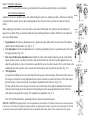
Page 11 Derailleur Adjustment
IMPORTANT: It is advised that you have a professional bicycle mechanic adjust the front or rear derailleur.
Rear Derailleur Adjustment
Adjustment to the rear derailleur can be done while turning the cranks, in a stationary position, while the rear wheel(s)
is elevated off the ground. Always make small adjustments first, then test while you rotate the crank and turn the
shifter.
Before adjusting the derailleur, be sure the chain is clean and well lubricated. Also, lubricate the shift cables and
inspect for any kinks. Dirty, dry or kinked cables will cause shifting hesitation or failure. Stiff links in the chain will
also cause shifting failure.
1.
2.
3.
4.
Top adjustment. Turn the top adjustment screw to position the guide pulley below the outer line of the smallest
sprocket when looking from the rear. (Fig. 11.1)
Low adjustment. Turn the low adjustment screw so that the guide pulley moves to a position directly in line with
the largest sprocket. (Fig. 11.2)
How to use the B-tension adjustment screw. Mount the chain on the smallest chain ring (on the crank) and the
largest sprocket (on the rear cluster), and turn crank arm backward. Then turn the b-tension adjustment screw to
adjust the guide pulley as close to the sprocket as possible but not so close that it touches. Next, set the chain to the
smallest sprocket and repeat the above to make sure that the pulley does not touch the sprocket. (Fig. 11.3)
SIS Adjustment.
(a) Operate the shifting lever to move the chain from the top gear to the second gear. If the chain will not move to
the 2nd gear, turn the outer casing adjustment barrel counter clockwise to increase the tension. If the chain moves
past the 2nd gear , decrease the tension by turning the adjustment barrel clockwise. (Fig. 11.4)
(b) Next with the chain on the 2nd gear, increase the inner cable tension by turning the adjustment barrel counter
clockwise while turning the crank arm forward. Stop turning the outer casing adjustment barrel just before the
chain makes noise against the 3rd gear. This completes the adjustment. (Fig. 11.5)
Note: For best SIS performance, periodically lubricate all power-transmission parts.
SPECIAL CAUTION:The adjusting barrel is for fine adjustments to the derailleur. If the barrel is turned too far counter-clockwise
it will screw out of its threads creating a hazardous condition. the adjusting barrel must be screwed in until a maximum of 3 threads
are showing. Removing the derailleur cable slack at the rear derailleur cable anchor makes “Coarse” adjustments to the system.
(Fig. 11.1)
(Fig. 11.2)
(Fig. 11.3)
(Fig. 11.4)
(Fig. 11.5)
Page 12
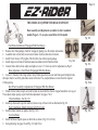
THIS MODEL IS EQUIPPED WITH REAR SUSPENSION
Basic assembly and adjustments are similar to other recumbent
models (Pages 4 - 11), except as noted below for this model.
1.
2.
3.
4.
5.
Fig. 16.1
Front Brake Installation (If Equipped With Disc Brakes)
Remove rotor from package, check for warpage by placing on a flat surface and examine.
Assemble rotor to front hub, arrow toward counter clockwise direction of rotation.
Install 6 Torx Screws (T25), tighten 55in-lbs (Nm). See reflector parts package.
Fig. 16.2
Install caliper on left side of fork brake mount attachment with 2-5mm hex bolts.
Connect brake cable to front caliper and tighten. Leave 2-3” of wire at end. For adjustment see Page 5.
Rotor Adjustment - Front Wheel (If Equipped With Disc Brakes)
1. Loosen 2 -5mm hex bolts. Align caliper. Keep 2.0mm space between rotor and brake pads. Retighten bolts,
then spin wheel to see if the pads make contact with rotor. If so, readjust distance to more than the required
2.0mm spacing.
Rear Wheel Assembly & Adjustments (If Equipped With Disc Brakes)
1. Similar to front wheel, except care must be taken to ensure that the chain is wrapped around the rear cog set.
Then, adjust caliper spacing as per front brake adjustment. See pages 7 & 8.
Chain Installation - See Fig. 16.1
1. Install top chain under top roller and lower chain on top of lower roller as illustrated in Fig.16.1
Pedal Installation (Models Equipped with FSA Crank)
1. Install included washers on pedals. (See Fig. 16.2)
Seat Installation
1. Install half moon shaped spacers on thru bolts as shown. (Fig. 16.3 & 16.3a)
Fig. 16.4a
2. Seat positioning. See page 10 and (Fig. 16.4 and 16.4a)
Fig. 16.3
Fig. 16.3a
Fig. 16.4
Page 13
Basic assembly and adjustments are
similar to other recumbent models
(Pages 4 - 11), except as noted below
for this model.
Fig. 17.1a
Handlebar Installation
1. Install stem in front fork and align to keep the upper handlebar unit aligned with
the front wheel. Tighten stem securely. (See Fig. 17.1)
2. Place upper handlebar unit on stem and insert hollow cylindrical spacer thru both
parts. Then, insert quick release assembly and align to comfort angle and tighten
securely. (See FIg. 17.1a)
3. Adjust handlebar to comfort angle by loosening stem bolt and
tightening as necessary.
Chain Installation
1. Install chain as per Fig 17.2 taking care to make sure that the chain exits the lower
pulley of the rear derailleur and crosses over the top of the roller. (See Fig. 17.2a)
Fig. 17.1
Fig. 17.2
Fig. 17.2a
Page 14
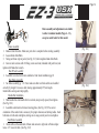
Basic assembly and adjustments are similar
to other recumbent models (Pages 4 - 11),
except as noted below for this model.
Frame Assembly
1. Remove trike from box. Make sure parts box is complete before starting assembly.
2. Loosen 6mm Allen Bolts.
3. Swing out frame at pivot point. (See Fig. 18.1) then retighten 6mm Allen Bolts.
4. Join rear axle sections with 10 fixing screws and nuts (included with parts box) and
tighten with 5mm allen wrench.
Rear Wheel Assembly
1. Assemble rear wheel with rotors similiar to front wheel installation pg.10
Rear Brake Assembly
1. See brake assembly pg. 7-8 . Note: make sure that rear brake cables are installed
correctly by length. Cut excess cable leaving approximately 2''(5cm) length.
Install cable end cap and crimp tightly.
Handle Bar Installation
1. Slide handle bars into handle bar tie rod ends, keep evenly spaced, then tighten.
(See Fig. 18.2)
2. Assemble control arm to fork and steering plate. (See Fig. 18.3) The correct
orientation of the control arm is necessary for proper clearance and turning radius. Insert
bolts/nuts on both ends and tighten, taking care to snug securely and not overtighten.
Front Brake Assembly
1. Route cable on the underside of frame and connect to right side of brake caliper.
Leave 2-3” at end of cable. (See Fig. 18.3)
(Fig. 18.1)
(Fig. 18.2)
(Fig. 18.3)
Page 15
CARE AND MAINTENANCE
WARNING: Do not ride your Sun Recumbent until both front and rear brakes have been checked and are functioning
properly. Keep all nuts, bolts and quick release levers well tightened. Lubricate cables occasionally to prevent binding.
Failure to do so may cause a malfunction, resulting in a serious or fatal accident. (See Front & Rear Brake Adjustment
page-5)
WARNING: Adjustment of the brake lever in too narrow a position may cause the lever to hit the handlebar before full
braking action is achieved. This is a dangerous situation. Recheck the brake lever position and make appropriate adjustments before riding. Failure to do so may result in inadequate or loss of brake power, resulting in a serious or fatal
accident.
Quick Release Lever Operation
CAUTION: Never fasten a wheel to a frame by rotating the quick release lever as shown in the diagram on the left
(Fig. 12.1). Simply rotating the lever in a circular motion will not fasten the wheel to the frame. Detachment of the
wheel as a result of improper hub installation can result in serious bodily injury.
NOTES
If the quick release lever can be easily pushed to the CLOSE position, this means the clamping strength is insufficient.
Return the quick release lever to the position perpendicular to the recumbent frame. And again turn the adjusting nut
clockwise to increase the clamping strength. Push the quick release lever back to the CLOSE position. (Fig. 12.2)
If the clamping strength is adjusted too strong and the quick release lever cannot be pushed to the CLOSE position,
turn the adjusting nut in a counter-clockwise direction to reduce the clamping strength. When doing this, do not fully
release the adjuster nut. Turn it 1/8 of a revolution, and then try to push the lever to CLOSE, to set the maximum
clamping strength with which you can push the quick release lever to the CLOSE position. (Fig. 12.3)
(Fig. 12.1)
(Fig. 12.2)
(Fig. 12.3)
POSITIONING OF THE QUICK RELEASE LEVER
For safety, the quick release lever should be along the recumbent frame when in the
CLOSE position.(Fig. 13.1)
Page 16
REMOVING THE WHEEL
(Fig. 13.1)
Move the quick release lever from CLOSE position to the OPEN position. Loosen the adjusting nut, and then remove
the wheel. (Fig. 13.2)
Quick Release Lever Operation (continued)
WARNING
THINGS TO CHECK BEFORE RIDING (Fig. 13.3)
1. Always check your quick release hubs before riding to make sure that the wheels are correctly installed on the
recumbent frame. This is especially important after you park your recumbent in a pubic place.
2. Make sure that the quick release levers are pushed fully to the CLOSE position (side of the lever with the
inscription "CLOSE" must be facing away from the wheel). As shown in the diagram, the lever must be lifted,
not rotated.
QUICK CHECK (Fig. 13.4)
Lift up the recumbent so that the wheel is off the ground, and give the top of the tire a few sharp downward blows as
shown in the diagram. The wheel should not be loose or come off. This check does not guarantee that the quick release
lever has received adequate tightening torque.
If you are uncertain as to whether the quick release is tightened correctly, repeat the installation procedure as explained
in “Quick Release Lever Operation on page-12.
Wheel Removal and Installation
Rear wheel removal (Bike)
1. Shift the rear derailleur into high gear (#7,small cog)
2. Release the rear brake cable by holding the rear brake shoes against the wheel rim and removing the guide pipe
from the holder on the brake arm. (Fig. 13.5)
3. Loosen quick release skewer.
(Fig. 13.2)
(Fig. 13.3)
(Fig. 13.4)
(Fig. 13.5)
Page 17
4.
Rear wheel removal (Bike) Continued
Pull the spring-loaded derailleur pulleys (and chain) towards the rear, while pulling the entire wheel out of the
frames axle slots (dropouts). (Fig. 14.1)
Rear wheel removal (Trike)
1. Loosen and remove axle nut. (Fig. 14.2)
Warning: Removal and installation of the rear wheel may cause misalignment of the rear derailleur. We recommend
your local Sun Bicycles dealer or bicycle mechanic do this procedure. Refer to Derailleur adjustment on page-7.
Also check rear brake adjustment refer to Brake Adjustments on page-5.
1.
2.
3.
4.
5.
1.
2.
Rear wheel installation
Installation is the reverse of removal.
Position the rear derailleur in its high gear (small cog).
Insert the wheel into the dropouts, making sure to catch the chain on the small freewheel cog.
Push the wheel firmly into the dropouts to center.
Close the quick-release lever firmly. (See Quick Release Operation on page-12)
Reattach the rear brake cable and check for brake adjustment. (See Brake Adjustment on page-5)
Rear wheel installation (Trike)
Both wheels are the same. The hub flanges have three holes that fit the studs on the axle flange. Install the drive
wheel first, (right side). Add axle washer on the outside and tighten locking nut securely. (Fig. 14.3)
Now put the second wheel on left side. This wheel is the idler. First slip on the spacer, then the wheel, followed by
a washer and the locking nut until it touches the bearing. Now loosen 1/2 turn. Again Do Not Over Tighten.
Leave Some Play. (Fig. 14.4)
(Fig. 14.1)
(Fig. 14.2)
(Fig. 14.3)
Warning: Very Important: It is critical for the protection of the bearings, that you inform your customer that the idler
wheel requires a slight amount of play in order to prevent bearing damage.
(Fig. 14.4)
1.
2.
3.
1.
2.
3.
1.
2.
3.
4.
5.
6.
Front Wheel Removal
Release the front brake cable by holding the front brake shoes against the wheel rim and
removing the guide pipe from the holder on the brake arm. (Fig. 15.1)
Open the quick-release lever and back the nut off a few turns to clear tabs on the fork.
Remove the wheel from the fork.
Front Wheel Installation
(Fig. 15.1)
Installation is the reverse of removal.
Push the wheel firmly into the fork to center.
Close the quick-release lever firmly. (See Quick Release Operation on page-12)
Reattach the front brake cable and check for brake adjustment. (See Brake Adjustment on page-5)
General Tire and Wheel Maintenance
Maintain tire pressure at the value indicated on the sidewall of the tire. (It’s common that most recumbent tires will
lose 5 to 10 psi a week.)
Never ride your recumbent with under-inflated tires, as this will cause poor handling, excessive tire wear
or blowout.
Use a hand or foot pump to inflate tire to proper tire pressure.
Over inflation or an improperly mounted tire may cause a blowout.
If there are any irregular noises from wheels, or if the rims wobble while rotating, check and repair wheels
immediately.
Wheels should be checked regularly for spoke tightness, especially if ridden on rough roads. If the wheel does not
remain 'true' this indicates that the spokes are loose. We recommend that spoke adjustments be performed by a
professional bicycle mechanic.
WARNING: Avoid riding over curbs. Watch for and avoid potholes, gratings and other road hazards. Walk your recumbent over railroad tracks, stairs, ditches or other such rough conditions. Failure to do so may result in tire failure, loss
of control, or other mechanical failures and may result in a serious or fatal accident.
Page 18
Page 19
Maintenance Check List
In order to keep your Sun Recumbent in top condition you should run a thorough maintenance check frequently.
This will ensure a longer component life of your Sun Recumbent.
General Recumbent Inspection
General inspection should be done before each ride and should include the following:
1. Check for loose nuts and bolts.
2. Check that all quick-release levers are securely fastened.
3. Check for fork and frame alignment.
4. Inspect brake pads for wear and replace when necessary.
5. Check for proper brake alignment.
6. Check for any worn or damaged parts and replace.
7. Look for loose spokes on the wheels. Check tires for glass, thorns or any other sharp objects.
8. Make sure both wheels are properly aligned.
9. Make sure handlebar stem bolts are tight and that the minimum insertion mark on the stem is not visible.
10. Keep the derailleurs in adjustment. Do not let the recumbent rest or fall on the derailleurs.
11. Keep tires inflated to the pressure indicated on the sidewall.
1.
2.
3.
4.
5.
6.
Component Lubrication
Drive chain: lubricate frequently in wet conditions and less often in dry conditions. Use bicycle chain lube.
Rear derailleur: Lubricate. (As needed)
Brake cables: Lubricate. (As needed)
Front and rear hub bearings: Grease. (Every 6 months)
Headset bearings: Grease. (Every 6 months)
Bottom bracket (crank) bearings: Grease. (Every 6 months)
Finish Protection and Maintenance
Surface finish can be protected by applying and maintaining a coat of high quality, non-abrasive wax or polish
(automobile wax is suitable). The stainless steel used in your Sun Recumbent is resistant to corrosion in most
atmospheric conditions; however, certain extreme environments may cause oxidizing of surfaces. We recommend either
maintaining a coat of wax or periodic polishing with a non-abrasive pad (e.g. typical dish cleaning pad).
We recommend storing your Sun Recumbent away from direct sunlight.
WARNING: Never wax, polish, or lubricate the sidewall of the rims or brake shoes.
Page 20
SUN BICYCLES LIMITED WARRANTY
J&B Importers, Inc. ("Sun Bicycles"), a Florida Corporation located at 11925 SW 128th St., Miami, FL 33186, makes the following Limited
Warranty concerning Sun Bicycles:
LIMITED 90-DAY WARRANTY ON COMPLETE RECUMBENT BICYCLE OR TRICYCLE Subject to the following limitations,
terms and conditions, Sun Bicycles warrants to the original owner of each new Sun Bicycles recumbent that this recumbent when new is free
of defective materials and workmanship. This warranty shall expire 90 days from the date of the original purchase from a Sun Bicycles dealer
and is conditioned upon the recumbent being operated under normal conditions and use, and properly maintained. This warranty is void if the
recumbent was not purchased new from or not properly assembled by a Sun Bicycles dealer.
LIMITED LIFETIME WARRANTY ON STEEL RECUMBENT FRAMES AND LIMITED TEN (10) YEAR WARRANTY ON ALL
OTHER RECUMBENT FRAMES Also subject to the following limitations, terms and conditions, Sun Bicycles warrants to the
original owner for the lifetime of the original owner of each new steel framed Sun Bicycles that the recumbent frame when new is free of
defective materials and workmanship. Sun Bicycles' limited warranty for all other recumbent frames, including aluminum based recumbent
frames, shall expire ten (10) years from the date of purchase from a Sun Bicycles dealer. The lifetime limited warranty and the ten (10) year
limited warranty are conditioned upon the recumbent being operated under normal conditions and use, and properly maintained. This limited
warranty does not apply to paint/finish or components attached to the recumbent/frameset such as front forks, wheels, drive train, brakes, seat
post, handlebar and stem or any suspension related parts or components. Paint/finish, components attached to the recumbent such as front
forks, wheels, drive train, brakes, seat post, handlebar and stem or any suspension related parts or components are covered under the limited
90 day warranty. This warranty is void if the recumbent was not purchased new from or not properly assembled by a Sun Bicycles dealer.
ADDITIONAL CONDITIONS This Limited Warranty is made only to the original owner of this new Sun Bicycles recumbent purchased
from a Sun Bicycles dealer, and it shall remain in force only as long as the original owner retains ownership of the Sun Bicycles recumbent.
This Limited Warranty is not transferable. In order to exercise your rights under this limited warranty, the recumbent must be presented to a
Sun Bicycles dealer, together with a receipt, bill of sale or other appropriate written proof of purchase which identifies the recumbent by
serial number. Should this recumbent, or any part be determined by Sun Bicycles to be covered by this warranty, it will be repaired or
replaced, at Sun Bicycles sole option, which will be conclusive and binding. The original owner shall pay all labor charges connected with
the repair or replacement of all parts. Under no circumstances does this limited warranty include the cost of travel or shipment to and from a
Sun Bicycles dealer. Such costs, if any, shall be borne by the original owner. This limited warranty does not apply to normal wear and tear,
nor to claimed defects, malfunctions or failures that result from abuse, neglect, improper assembly, improper maintenance, alteration, collision, crash or misuse. This recumbent has not been designed, engineered, distributed, manufactured, or retailed for uses in trick riding, ramp
riding, jumping,
Page 21
aggressive riding, riding on severe terrain, riding in severe climates, riding with heavy loads, commercial activities, or any similar activities;
such uses may damage the recumbent, and can cause serious injury to the rider, and in all cases will void this warranty.
USEFUL PRODUCT LIFE CYCLE Every Sun Bicycles recumbent and frameset has a useful product life cycle. The length of that useful
product life cycle will vary with the construction and materials of the recumbent or frameset, the maintenance and care the recumbent or
frameset receives over its useful product life cycle, and the type and amount of use the recumbent or frameset is subject to. Uses in competitive events, trick riding, ramp riding, jumping, aggressive riding, riding on severe terrain, riding in severe climates, riding with heavy loads,
commercial activities and other types of non-standard use can dramatically shorten the useful product life cycle of a Sun Bicycles recumbent.
Any one or a combination of these conditions may result in an unpredictable failure of a Sun Bicycles recumbent that would not be covered
by this warranty. All Sun Bicycle recumbents should be periodically checked by a Sun Bicycles dealer, for indicators of stress and/or potential
failure, including cracks, deformation, corrosion, paint peeling, dents, and any other indicators of potential problems, inappropriate use, or
abuse. These are important safety checks and very important to help prevent accidents, bodily injury to the rider and shortened useful product
life cycle of a Sun Bicycles recumbent.
THIS IS AN INTEGRATED AND FINAL STATEMENT OF SUN BICYCLES LIMITED WARRANTY. SUN BICYCLES DOES NOT
AUTHORIZE OR ALLOW ANYONE, INCLUDING ITS DEALERS, TO EXTEND ANY OTHER WARRANTIES, EXPRESS OR
IMPLIED, FOR SUN BICYCLES. NO OTHER REPRESENTATION, AND NO STATEMENT OF ANYONE BUT SUN BICYCLES,
INCLUDING A DEMONSTRATION OF ANY KIND BY ANYONE SHALL CREATE ANY WARRANTY REGARDING THIS
RECUMBENT. ALL OF THE REMEDIES AVAILABLE TO THE ORIGINAL OWNER ARE STATED HEREIN. IT IS AGREED THAT
SUN BICYCLES' LIABILITY UNDER THIS LIMITED WARRANTY SHALL BE NO GREATER THAN THE AMOUNT OF THE
ORIGINAL PURCHASE PRICE AND IN NO EVENT SHALL SUN BICYCLES BE LIABLE FOR INCIDENTAL OR CONSEQUENTIAL
DAMAGES.
DISCLAIMER All other remedies, obligations, liabilities, rights, warranties, express or implied, arising from law or otherwise, including
but not limited to, any claimed implied warranty of merchantability, any claimed implied warranty arising from course of performance,
course of dealing or usage of trade, and any claimed implied warranty of fitness, are disclaimed by Sun Bicycles and waived by the original
owner. Some states, jurisdictions, countries, provinces, do not allow some or all of the limitations set for herein, or the exclusion or limitation
of incidental or consequential damages. If any provision is found unenforceable, only that provision shall be stricken and all others shall
apply. This limited warranty does provide the original owner with certain legal rights and recourse and the original owner may possess other
rights or recourse, depending on the state, jurisdiction, country or province.
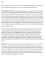
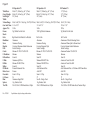
Wheel Base:
Overall Length:
Seat Height:
Width:
X-Seam Range:
Gear Inch Value:
Approx. Wt.:
Frame:
Shock:
Fork:
Handlebar:
Stem:
Headset:
B.B.:
Crank:
F. Derailleur:
R. Derailleur:
F. Hub:
R. Hub:
Shifter:
F/R Brake:
Brake Lever:
Freewheel:
# of Gears:
Rim:
Spokes:
Tire F/R:
Rev. 12/2004
EZ-1SX
56.5'' (143cm)
73'' (185cm)
24.5"(62mm)
EZ-1 AX
56.5" (143cm)
73'' (185cm)
24.5"(62mm)
EZ-1 DSX
56.5" (143cm)
73'' (185cm)
24.5"(62mm)
34-48" (84-122cm)
17.5 to 83"
39 lbs.
High Tensile Tig Welded Steel
34-48" (84-122cm)
17.5 to 90"
34 lbs.
7005 Tig Welded Aluminum
34-48" (84-122cm)
14.5 to 78.5"
42 lbs.
High Tensile Tig Welded Steel
High Tensile Steel Blades/Cro-Mo Steerer
Steel w/2 Bottle Mounting Points
Aluminum 240mm Recumbent
Sealed Mechanism Steel
Standard
Aluminum 170x52/42/30 (steel rings)
Shimano
Sram 3.0
Aluminum Q/R
Shimano FH-RM40-8
Sram 3.0 w/Brake Lever
Tektro Aluminum Linear Pull
Sram 3.0
Sram 11-32 8sp
24
Aluminum Single Wall
14g. Stainless Steel
16x1.50/20x1.50 BW Kenda Kwest
High Tensile Steel Blades/Cro-Mo Steerer
Aluminum w/2 Bottle Mounting Points
Aluminum 240mm Quill /60mm Ahead
Oversized Integrated Style
Sealed Cartridge
Aluminum 170x53/42/30 (Aluminum Rings)
Shimano
Sram 4.0
Aluminum Q/R
Shimano FH-RM40-8
Sram 4.0
Avid SD-3 Linear Pull
Avid FR-1
Sram 11-32 8sp
24
Aluminum Single Wall
14g. Stainless Steel
16x1.50/20x1.50 BW Kenda Kwest 100psi
High Tensile Steel Blades/Cro-Mo Steerer
Steel w/2 Bottle Mounting Points
Aluminum 240mm Recumbent
Sealed Mechanism Steel
Sealed Cartridge
Aluminum 170x34t
Specifications subject to change without notice.
Sram Dual Drive
Aluminum Q/R
Sram Dual Drive 8sp
Sram Dual Drive
Avid SD-3 Linear Pull
Avid FR-1
Sram 11-32 8sp Dual Drive
24
Aluminum Single Wall
14g. Stainless Steel
16x1.50/20x1.50 BW Kenda Kwest
Page 22
Page 23
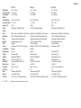
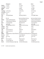
Wheel Base:
Overall Length:
Seat Height:
Width:
X-Seam Range:
Gear Inch Value:
Approx. Wt.:
Frame:
Shock:
Fork:
Handlebar:
Stem:
Headset:
B.B.:
Crank:
F. Derailleur:
R. Derailleur:
F. Hub:
R. Hub:
Shifter:
F/R Brake:
Brake Lever:
Freewheel:
# of Gears:
Rim:
Spokes:
Tire F/R:
Rev. 12/2004
EZ-Sport CX
62" (157.5cm)
85.5" (217cm)
26.5" (67cm)
EZ-Sport AX
62" (157.5cm)
85.5" (217cm)
26.5" (67cm)
36-45" (91-114cm)
31.1 to 117.6"
40 lbs.
Tig Welded Cro-Mo Steel
36-45" (91-114cm)
31.1 to 117.6"
34 lbs.
7005 Tig Welded Aluminum
EZ-Rider SX
59.5" (151cm)
79'' (200cm)
25.5"(65mm)
34-46" (84-117cm)
17.5 to 88.3"
45 lbs.
High Tensile Tig Welded Steel
A-Pro SD
Full Cro-Mo
Full Cro-Mo
High Tensile Steel Blades/Cro-Mo Steerer
Aluminum w/2 Bottle Mounting Points
Aluminum w/2 Bottle Mounting Points
Steel w/2 Bottle Mounting Points
Aluminum 240mm Quill w/60mm Ahead
Aluminum 240mm Quill w/60mm Ahead
Aluminum 240mm Quill w/60mm Ahead
Oversized Aluminum Sealed Mechanism
Oversized Integrated Style
Sealed Mechanism Steel
Sealed Cartridge
Sealed Cartridge
Standard
Shimano Sora FC-3303 170x52/42/30
Shimano Tiagra FC-4403 170x52/42/30
Aluminum 170x52/42/30 (steel rings)
Shimano
Shimano
Shimano
Sram 4.0
Sram X9
Sram 3.0
Shimano HB-MC12
Shimano Doere LX HB-M570
Aluminum Q/R
Shimano FH-MC18
Shimano Deore LX FH-M570
Shimano FH-RM40-8
Sram 4.0
Sram X9
Sram 3.0 w/Brake Lever
Avid SD-3 Linear Pull
Avid SD-5 Linear Pull
Tektro Aluminum Linear Pull
Avid FR-1
Avid
Sram 3.0
Sram 11-32 8sp
Sram 11-32 9sp
Sram 11-32 8sp
24
27
24
Aluminum Single Wall
Aluminum Dbl. Wall w/CNC Side Wall & Eyelets Aluminum Single Wall
14g. Stainless Steel
14g. Stainless Steel
14g. Stainless Steel
20x1.50/26x1.50 BW Kenda Kwest 100psi 20x1.50/26x1.50 BW Kenda Kwest 100psi
20x1.50 BW Kenda On/Off Road
Specifications subject to change without notice.
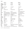
Wheel Base:
Overall Length:
Seat Height:
Width:
X-Seam Range:
Gear Inch Value:
Approx. Wt.:
Frame:
Shock:
Fork:
Handlebar:
Stem:
Headset:
B.B.:
Crank:
F. Derailleur:
R. Derailleur:
F. Hub:
R. Hub:
Shifter:
F/R Brake:
Brake Lever:
Freewheel:
# of Gears:
Rim:
Spokes:
Tire F/R:
Rev. 12/2004
EZ-Rider CX
59.5" (151cm)
79" (200cm)
25.5" (65cm)
34-46" (88-117cm)
17.5 to 88.3"
42 lbs.
Tig Welded Cro-Mo Steel
A-Pro SSD
High Tensile Steel Blades/Cro-Mo Steel
Aluminum w/2 Bottle Mounting Points
Aluminum 240mm Quill w/60mm Ahead
Oversized Aluminum Sealed Mechanism
Sealed Cartridge
Shimano FC-2203 170x52/42/30
Shimano
Sram 4.0
Aluminum Q/R Disc
Shimano FH-M475 Disc
Sram 4.0
Promax Mechanical Disc
Promax
Sram 11-32 8sp
24
Aluminum Single Wall
14g. Stainless Steel
20x1.50 BW Kenda On/Off Road 100psi
Specifications subject to change without notice.
EZ-Rider AX
59.5" (151cm)
79" (200cm)
25.5" (65cm)
EZ-Speedster SX
Med. 43" (109cm) Lrg. 46" (117cm)
Med. 66" (167cm) Lrg. 69" (175cm)
24.6" (61cm)
34-46" (88-117cm)
17.5 to 88.3"
40 lbs.
7005 Tig Welded Aluminum
A-Pro Tough Shock
Full Cro-Mo
Aluminum w/2 Bottle Mounting Points
Aluminum 240mm Quill w/60mm Ahead
Oversized Integrated Style
Sealed Cartridge
Shimano FC-2203 170x52/42/30
Shimano
Sram X9
Shimano HB-M475 Disc
Shimano FH-M475 Disc
Sram X9
Avid Mechanical Disc
Avid SD-7
Sram 11-32 9sp
27
Sun SL-1 Single Track
14g. Stainless Steel
20x1.50 BW Kenda On/Off Road 100psi
Med. 36-46" (91-117cm) Lrg. 39-49" (99-125cm)
31.1 to 117.6"
41 lbs.
High Tensile Tig Welded Steel
High Tensile Steel Blades/Cro-Mo Steerer
Steel
Aluminum Pivoting
Sealed Mechanism Steel
Standard
Aluminum 170x52/42/30 (steel rings)
Shimano
Sram 3.0
Aluminum Q/R
Shimano FH-RM40-8
Sram 3.0 w/Brake Lever
Tektro Aluminum Linear Pull
Sram 3.0
Sram 11-32 8sp
24
Aluminum Single Wall
14g. Stainless Steel
20x1.50/26x1.50 BW Kenda Kwest
Page 24
Page 25
Wheel Base:
Overall Length:
Seat Height:
Width:
X-Seam Range:
Gear Inch Value:
Approx. Wt.:
Frame:
Shock:
Fork:
Handlebar:
Stem:
Headset:
B.B.:
Crank:
F. Derailleur:
R. Derailleur:
F. Hub:
R. Hub:
Shifter:
F/R Brake:
Brake Lever:
Freewheel:
# of Gears:
Rim:
Spokes:
Tire F/R:
Rev. 12/2004
EZ-Speedster CX
Med. 43" (109cm) Lrg. 46" (117cm)
Med. 66" (167cm) Lrg. 69" (175cm)
24" (61cm)
EZ-Speedster AX
Med. 43" (109cm) Lrg. 46" (117cm)
Med. 66" (167cm) Lrg. 69" (175cm)
24" (61cm)
Med. 36-46"(91-117cm) Lrg. 39-49"(99-125cm)
31.1 to117.6"
38 lbs.
Tig Welded Cro-Mo Steel
Med. 36-46"(91-117cm) Lrg. 39-49"(99-125cm) 36-44" (91-112cm)
31.1 to117.6”
21.9 to 117.6"
36 lbs.
59 lbs.
7005 Tig Welded Aluminum
Tig Welded Cro-Mo Steel
High Tensile Steel Blades/Cro-Mo Steel
Aluminum
Aluminum Pivoting
Oversized Aluminum Sealed Mechanism
Sealed Cartridge
Shimano FC-2203 170x52/42/30
Shimano
Sram 4.0
Aluminum Q/R Disc
Shimano FH-M475 Disc
Sram 4.0
Promax Mechanical Disc
Promax
Sram 11-32 8sp
24
Aluminum Single Wall
14g. Stainless Steel
20x1.50/26x1.50 BW Kenda Kwest 100psi
Specifications subject to change without notice.
Full Cro-Mo
Aluminum
Aluminum Pivoting
Oversized Integrated Style
Sealed Cartridge
Shimano FC-2203 170x52/42/30
Shimano
Sram X9
Shimano HB-M475 Disc
Shimano FH-M475 Disc
Sram X9
Avid Mechanical Disc
Avid SD-7
Sram 11-32 9sp
27
Sun SL-1 Single Track
14g. Stainless Steel
20x1.50 BW Kenda Kwest 100psi
EZ-Tandem CX
91" (231cm)
113" (237cm)
28" (71cm)
Full Cro-Mo
Aluminum w/2 Bottle Mounting Points
Aluminum 240mm Quill w/60mm Ahead
Oversize Aluinum Sealed Mechanism
Sealed Cartridge
Aluminum Tandem 170x52/42/30
Shimano
Sram 5.0
American Classic Disc 36H
American Classic Disc 48H
Sram 5.0
Avid Mechanical Disc w/F/160mm & R/203mm Rotor
Avid FR-1
Sram 11-34 9sp
27
Sun SL-1 Single Track
14g. Stainless Steel
20x1.50/26x1.50 BW Kenda Kwest Tandem 100psi
Wheel Base:
Overall Length:
Seat Height:
Width:
X-Seam Range:
Gear Inch Value:
Approx. Wt.:
Frame:
Shock:
Fork:
Handlebar:
Stem:
Headset:
B.B.:
Crank:
F. Derailleur:
R. Derailleur:
F. Hub:
R. Hub:
Shifter:
F/R Brake:
Brake Lever:
Freewheel:
# of Gears:
Rim:
Spokes:
Tire F/R:
Rev. 12/2004
EZ-Tandem AX
91" (231cm)
113" (237cm)
28" (71cm)
Page 26
36-44" (91-112cm)
21.9 to 117.6"
54 lbs.
7005 Tig Welded Aluminum
EZ-3 SX
56.5" (143cm)
73" (185cm)
22" (56cm)
30.5" (77.5cm)
32-48" (81-122cm)
19 to 71"
56 lbs..
High Tensile Tig Welded Steel
EZ-3 AX
56" (142cm)
75" (191cm)
19.5" (50cm)
30" (76cm)
32-48" (81-122cm)
17.8 to 90.2"
50 lbs.
7005 Tig Welded Aluminum
Full Cro-Mo
Aluminum w/2 Bottle Mounting Points
Aluminum 240mm Quill w/60mm Ahead
Oversized Integrated Style
Sealed Cartridge
IPS Aluminum Tandem 170x52/42/30
Shimano
Sram X9
American Classic Disc 36H
American Classic Disc 48H
Sram X9
Avid Mechanical Disc w/F/160mm & R/203mm Rotor
Avid SD-7
Sram 11-34 9sp
27
Sun SL-1 Single Track
F/14g. R/13g. Stainless Steel
20x1.50/26x1.50 BW Kenda Kwest Tandem 100psi
High Tensile Steel Blades/Cro-Mo Steerer
Steel w/2 Bottle Mounting Points
Aluminum 240mm Recumbent
Sealed Mechanism Steel
Standard
Aluminum 170x52/42/30 (steel rings)
Shimano
Sram 3.0
Aluminum Q/R
Aluminum
Sram 3.0
Tektro Aluminum Linear Pull/Promax Mech. Disc
Promax w/Parking Lock
Shimano 13-28 7sp
21
Aluminum Single Wall
14g. Stainless Steel
16x1.50/20x1.50 BW Kenda Kwest
High Tensile Steel Blades/Cro-Mo Steerer
Aluminum w/2 Bottle Mounting Points
Aluminum 240mm Quill w/60mm Ahead
Oversize Integrated Style
Sealed Cartridge
Shimano FC-2203 170x52/42/30
Shimano
Sram 5.0
Aluminum Q/R Disc
Aluminum
Sram 5.0
Promax Mechanical Disc
Promax w/Parking Lock
Sram 11-32 8sp
27
Sun SL-1Single Track
14g. Stainless Steel
20x1.50 BW Kenda Kwest 100psi
Specifications subject to change without notice.
Page 27
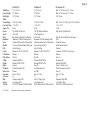
Wheel Base:
Overall Length:
Seat Height:
Width:
X-Seam Range:
Gear Inch Value:
Approx. Wt.:
Frame:
Shock:
Fork:
Handlebar:
Stem:
Headset:
B.B.:
Crank:
F. Derailleur:
R. Derailleur:
F. Hub:
R. Hub:
Shifter:
F/R Brake:
Brake Lever:
Freewheel:
# of Gears:
Rim:
Spokes:
Tire F/R:
Rev. 12/2004
EZ-3 USX
EZ-3 SX Tadpole
EZ-3 CX Tadpole
59.5" (151cm)
(Not Available)
(Not Available)
78" (198cm)
(Not Available)
(Not Available)
18" (45cm)
(Not Available)
(Not Available)
32" (81cm)
32” (81cm)
32” (81cm)
37-46" (94-117cm)
(Not Available)
(Not Available)
20.0 to 88.3"
(Not Available)
(Not Available)
65 lbs.
(Not Available).
(Not Available)
High Tensile Tig Welded Steel
High Tensile Tig Welded Steel
Tig Welded Cro-Mo Steel
AN-6 Aluminum w/Spring
High Tensile Steel
High Tensile Steel
High Tensile Steel
Steel
Steel
Steel
Aluminum Ahead
Aluminum Ahead
Aluminum Ahead
Sealed Mechanism Steel
Sealed Mechanism Steel
Sealed Mechanism Steel
Standard
Sealed Cartridge
Sealed Cartridge
Aluminum 170x52/42/30 (steel rings) Aluminum 170x52/42/30 (steel rings) FSA 170x53/42/30
Shimano
Shimano
Shimano
Sram 3.0
Sram 3.0
Sram X7
Aluminum Q/R
Aluminum Tadpole
Aluminum Tadpole
Aluminum
Promax DB-600R
Promax DB-910R
Sram 3.0
Sram 3.0
Sram X7
Aluminum Linear Pull/Dual Disc
Quad QMD-6 Mechanical Disc
Quad QMD-5 Mechanical Disc
Aluminum w/Parking Lock
Promax w/Parking Lock
Promax w/Parking Lock
Sram 11-28 7sp
Sram 11-32 8sp
Sram 11-32 9sp
21
24
27
Aluminum Single Wall
Aluminum Single Wall
Alex DA-16
14g. Stainless Steel
14g. Stainless Steel
14g. Stainless Steel
20x1.50 BW Kenda Kwest
20x1.50 BW Kenda Kwest
20x1.50 BW Kenda Kwest 100psi
Specifications subject to change without notice.
.sunbicycles.
www
com
BICYCLES
BICYCLES
EST.
1971
Sun Bicycle Co. Div. of J&B Importers, Inc.
11925 South West 128th. Street
Miami, Florida USA 33186, 305-238-1866


![4403002491_712_716 menu_EN_A [s]](http://vs1.manualzilla.com/store/data/005650300_1-96030b29e24dd373b0bced3bef593dda-150x150.png)