1
Document 9504
9710 Library
Storage Module
Hardware Operator’s Guide
9710 Library
Storage Module
Hardware Operator’s Guide
Information contained in this publication is subject to change without notice. Comments
concerning the contents of this publication should be directed to:
Information Development
Storage Technology Corporation
One StorageTek Drive
Louisville, CO 80028-2201
USA
URL: http://sts.stortek.com/sts/nid
A Reader’s Comment Form at the back of this publication lets you communicate suggestions or
requests for change. StorageTek encourages and appreciates reader feedback.
StorageTek, the signature, and Information Made Powerful are trademarks of Storage
Technology Corporation. Other product names, features, and terms used in this publication are
for informational purposes only and might be trademarks of Storage Technology Corporation
or of other companies.
©1995, 2001 by Storage Technology Corporation, Louisville, Colorado, USA. All rights reserved.
Printed in the USA.
ii
Sixteenth Edition
9504
Summary of Changes
EC released document table
EC Number
Date
Type
Change
111322
December
1995
Initial Release
See this publication for specific information.
111301
December
1999
Fifteenth
Edition
See this publication for specific information.
111689
December
2001
Sixteenth
Edition
Updated template. Added SDLT 220 and
T9840B Drive information.
9504
Sixteenth Edition
iii
Summary of Changes
This page intentionally left blank.
iv
Sixteenth Edition
9504
Contents
Summary of Changes . . . . . . . . . . . . . . . . . . . . . . . . . . . . . . . . . . . . . . . . . . . . . . iii
Contents . . . . . . . . . . . . . . . . . . . . . . . . . . . . . . . . . . . . . . . . . . . . . . . . . . . . . . . . . v
Figures . . . . . . . . . . . . . . . . . . . . . . . . . . . . . . . . . . . . . . . . . . . . . . . . . . . . . . . . . viii
Tables . . . . . . . . . . . . . . . . . . . . . . . . . . . . . . . . . . . . . . . . . . . . . . . . . . . . . . . . . . . ix
Preface . . . . . . . . . . . . . . . . . . . . . . . . . . . . . . . . . . . . . . . . . . . . . . . . . . . . . . . . . . xi
Organization . . . . . . . . . . . . . . . . . . . . .
Trademarks . . . . . . . . . . . . . . . . . . . . . .
Alert Messages . . . . . . . . . . . . . . . . . . .
Conventions . . . . . . . . . . . . . . . . . . . . .
Related Publications . . . . . . . . . . . . . . .
Additional Information . . . . . . . . . . . . . .
StorageTek’s External Web Site . . . . .
Customer Resource Center . . . . . . . .
e-Partners Site . . . . . . . . . . . . . . . . .
Hardcopy Publications . . . . . . . . . . .
Comments and Suggestions . . . . . . . . . .
.
.
.
.
.
.
.
.
.
.
.
.
.
.
.
.
.
.
.
.
.
.
.
.
.
.
.
.
.
.
.
.
.
.
.
.
.
.
.
.
.
.
.
.
.
.
.
.
.
.
.
.
.
.
.
.
.
.
.
.
.
.
.
.
.
.
.
.
.
.
.
.
.
.
.
.
.
.
.
.
.
.
.
.
.
.
.
.
.
.
.
.
.
.
.
.
.
.
.
.
.
.
.
.
.
.
.
.
.
.
.
.
.
.
.
.
.
.
.
.
.
.
.
.
.
.
.
.
.
.
.
.
.
.
.
.
.
.
.
.
.
.
.
.
.
.
.
.
.
.
.
.
.
.
.
.
.
.
.
.
.
.
.
.
.
.
.
.
.
.
.
.
.
.
.
.
.
.
.
.
.
.
.
.
.
.
.
.
.
.
.
.
.
.
.
.
.
.
.
.
.
.
.
.
.
.
.
.
.
.
.
.
.
.
.
.
.
.
.
.
.
.
.
.
.
.
.
.
.
.
.
.
.
.
.
.
.
.
.
.
.
.
.
.
.
.
.
.
.
.
.
.
.
.
.
.
.
.
.
.
.
.
.
.
.
.
.
.
.
.
.
.
.
.
.
.
.
.
.
.
.
.
.
.
.
.
.
.
.
.
.
.
.
.
.
.
.
.
.
.
.
.
.
.
.
.
.
.
.
.
.
.
.
.
.
.
.
.
.
.
.
.
.
.
.
.
.
.
.
.
.
.
.
.
.
.
.
.
.
.
.
.
.
.
.
.
.
.
.
.
.
.
.
.
.
.
.
.
.
.
.
.
.
.
.
.
.
.
.
.
.
.
.
.
. xi
.xii
.xii
.xii
xiii
xiv
xiv
.xv
.xv
.xv
.xv
Safety, Fiber Optic, and ESD . . . . . . . . . . . . . . . . . . . . . . . . . . . . . . . . . . . . . . . xvi
Safety Precautions . . . . . . . . . . . . . . . . . . . . . . . . . . . . . . . . . . . . . . . . . . . . . . . . . . . xvi
Lifting Techniques . . . . . . . . . . . . . . . . . . . . . . . . . . . . . . . . . . . . . . . . . . . . . . . . xvii
Shoulder, Elbow, Wrist, and Hand Safety . . . . . . . . . . . . . . . . . . . . . . . . . . . . . . . xvii
Fiber Optic Safety . . . . . . . . . . . . . . . . . . . . . . . . . . . . . . . . . . . . . . . . . . . . . . . . . . xviii
Laser Product Label . . . . . . . . . . . . . . . . . . . . . . . . . . . . . . . . . . . . . . . . . . . . . . . . . . xix
Fiber-Optic Cable Handling . . . . . . . . . . . . . . . . . . . . . . . . . . . . . . . . . . . . . . . . . . . . xix
Electrostatic Discharge (ESD) Damage Prevention . . . . . . . . . . . . . . . . . . . . . . . . . . . . .xx
ESD Precautions . . . . . . . . . . . . . . . . . . . . . . . . . . . . . . . . . . . . . . . . . . . . . . . . . .xx
ESD-Protection Procedure . . . . . . . . . . . . . . . . . . . . . . . . . . . . . . . . . . . . . . . . . . xxi
Prepare the Work Area . . . . . . . . . . . . . . . . . . . . . . . . . . . . . . . . . . . . . . . . . . xxi
Access the Equipment . . . . . . . . . . . . . . . . . . . . . . . . . . . . . . . . . . . . . . . . . . xxi
Replace Components . . . . . . . . . . . . . . . . . . . . . . . . . . . . . . . . . . . . . . . . . . . xxi
Clean Up . . . . . . . . . . . . . . . . . . . . . . . . . . . . . . . . . . . . . . . . . . . . . . . . . . . . xxii
9710 Interlocks . . . . . . . . . . . . . . . . . . . . . . . . . . . . . . . . . . . . . . . . . . . . . . . . . . . . . xxii
Notices . . . . . . . . . . . . . . . . . . . . . . . . . . . . . . . . . . . . . . . . . . . . . . . . . . . . . . . . xxiii
FCC Compliance Statement . . . . . . . . . . . . . . . . . . . . . . . . . . . . . . . . . . . . . . . . . . . xxiii
9504
Sixteenth Edition
v
Contents
CISPR 22 and EN55022 Warning .
Japanese Compliance Statement .
Taiwan Warning Label Statement
Internal Code License Statement .
.
.
.
.
.
.
.
.
.
.
.
.
.
.
.
.
.
.
.
.
.
.
.
.
.
.
.
.
.
.
.
.
.
.
.
.
.
.
.
.
.
.
.
.
.
.
.
.
.
.
.
.
.
.
.
.
.
.
.
.
.
.
.
.
.
.
.
.
.
.
.
.
.
.
.
.
.
.
.
.
.
.
.
.
.
.
.
.
.
.
.
.
.
.
.
.
.
.
.
.
.
.
.
.
.
.
.
.
.
.
.
.
.
.
.
.
.
.
.
.
.
.
.
.
.
.
.
.
.
.
.
.
.
.
.
.
.
.
.
.
.
.
.
.
.
.
.
.
.
.
.
.
.
.
.
.
xxiii
xxiv
xxiv
. xxv
1: General Information . . . . . . . . . . . . . . . . . . . . . . . . . . . . . . . . . . . . . . . . . . . .1-1
Library Storage Module Components
Robot . . . . . . . . . . . . . . . . . . . .
Storage Cells . . . . . . . . . . . . . . .
Cartridge Access Port . . . . . . . .
Drives . . . . . . . . . . . . . . . . . . . .
LSM Safety Features . . . . . . . . . . . .
Controlling Software . . . . . . . . . . . .
Library Operating Modes . . . . . . . . .
Automated Mode . . . . . . . . . . . .
Manual Mode . . . . . . . . . . . . . .
AUTO CLEAN Feature . . . . . . . . . . .
.
.
.
.
.
.
.
.
.
.
.
.
.
.
.
.
.
.
.
.
.
.
.
.
.
.
.
.
.
.
.
.
.
.
.
.
.
.
.
.
.
.
.
.
.
.
.
.
.
.
.
.
.
.
.
.
.
.
.
.
.
.
.
.
.
.
.
.
.
.
.
.
.
.
.
.
.
.
.
.
.
.
.
.
.
.
.
.
.
.
.
.
.
.
.
.
.
.
.
.
.
.
.
.
.
.
.
.
.
.
.
.
.
.
.
.
.
.
.
.
.
.
.
.
.
.
.
.
.
.
.
.
.
.
.
.
.
.
.
.
.
.
.
.
.
.
.
.
.
.
.
.
.
.
.
.
.
.
.
.
.
.
.
.
.
.
.
.
.
.
.
.
.
.
.
.
.
.
.
.
.
.
.
.
.
.
.
.
.
.
.
.
.
.
.
.
.
.
.
.
.
.
.
.
.
.
.
.
.
.
.
.
.
.
.
.
.
.
.
.
.
.
.
.
.
.
.
.
.
.
.
.
.
.
.
.
.
.
.
.
.
.
.
.
.
.
.
.
.
.
.
.
.
.
.
.
.
.
.
.
.
.
.
.
.
.
.
.
.
.
.
.
.
.
.
.
.
.
.
.
.
.
.
.
.
.
.
.
.
.
.
.
.
.
.
.
.
.
.
.
.
.
.
.
.
.
.
.
.
.
.
.
.
.
.
.
.
.
.
.
.
.
.
.
.
.
.
.
.
.
.
.
.
.
.
.
.
.
.
.
.
.
.
.
.
.
.
.
.
.
.
.
.
.
.
.
.
.
.
.
.
.
.
.
.
.
.
.
.
.
.
.
.
.
.
.
.
.
.
.
.
.
.
.
.
.
.
.
.
.
.
.
.
.
.
.
.
.
.
.
.
.
.
.
.
.
.
1-1
1-1
1-3
1-7
1-7
1-8
1-8
1-8
1-8
1-9
1-9
2: Controls and Indicators . . . . . . . . . . . . . . . . . . . . . . . . . . . . . . . . . . . . . . . . .2-1
Using the Operator Panel . . . . . . . . . . .
Viewing and Setting Configuration Data
Setting the DMS Host Number . . . .
Setting Cleaning Cartridge Count . .
Locating the LSM’s Power Switches . . .
.
.
.
.
.
.
.
.
.
.
.
.
.
.
.
.
.
.
.
.
.
.
.
.
.
.
.
.
.
.
.
.
.
.
.
.
.
.
.
.
.
.
.
.
.
.
.
.
.
.
.
.
.
.
.
.
.
.
.
.
.
.
.
.
.
.
.
.
.
.
.
.
.
.
.
.
.
.
.
.
.
.
.
.
.
.
.
.
.
.
.
.
.
.
.
.
.
.
.
.
.
.
.
.
.
.
.
.
.
.
........
........
........
........
........
.....
.....
.....
.....
.....
2-1
2-2
2-5
2-7
2-9
3: Operating the LSM . . . . . . . . . . . . . . . . . . . . . . . . . . . . . . . . . . . . . . . . . . . . . .3-1
Powering on or IPLing the LSM . . . . . . . . . . . . .
Powering off the LSM . . . . . . . . . . . . . . . . . . . .
Operating in Automated Mode . . . . . . . . . . . . . .
Entering Cartridges through the CAP . . . . . . .
Removing Cartridges through the CAP . . . . .
Replacing the Cleaning Cartridge . . . . . . . . .
Operating in Manual Mode . . . . . . . . . . . . . . . .
Opening the LSM Front Doors . . . . . . . . . . .
Moving the Robot . . . . . . . . . . . . . . . . . . . .
Raising and Lowering the Z Carriage . . . .
Rotating the Z Column . . . . . . . . . . . . . .
Locating a Cartridge in the Storage Cells . . . .
Removing a Cartridge from the Hand . . . . . .
Loading a Cartridge into a 4890 Drive . . .
Unloading a Cartridge from a 4890 Drive
Loading a Cartridge into a DLT Drive . . .
Unloading a Cartridge from a DLT Drive .
vi
.
.
.
.
.
.
.
.
.
.
.
.
.
.
.
.
.
Sixteenth Edition
.
.
.
.
.
.
.
.
.
.
.
.
.
.
.
.
.
.
.
.
.
.
.
.
.
.
.
.
.
.
.
.
.
.
.
.
.
.
.
.
.
.
.
.
.
.
.
.
.
.
.
.
.
.
.
.
.
.
.
.
.
.
.
.
.
.
.
.
.
.
.
.
.
.
.
.
.
.
.
.
.
.
.
.
.
.
.
.
.
.
.
.
.
.
.
.
.
.
.
.
.
.
.
.
.
.
.
.
.
.
.
.
.
.
.
.
.
.
.
.
.
.
.
.
.
.
.
.
.
.
.
.
.
.
.
.
.
.
.
.
.
.
.
.
.
.
.
.
.
.
.
.
.
.
.
.
.
.
.
.
.
.
.
.
.
.
.
.
.
.
.
.
.
.
.
.
.
.
.
.
.
.
.
.
.
.
.
.
.
.
.
.
.
.
.
.
.
.
.
.
.
.
.
.
.
.
.
.
.
.
.
.
.
.
.
.
.
.
.
.
.
.
.
.
.
.
.
.
.
.
.
.
.
.
.
.
.
.
.
.
.
.
.
.
.
.
.
.
.
.
.
.
.
.
.
.
.
.
.
.
.
.
.
.
.
.
.
.
.
.
.
.
.
.
.
.
.
.
.
.
.
.
.
.
.
.
.
.
.
.
.
.
.
.
.
.
.
.
.
.
.
.
.
.
.
.
.
.
.
.
.
.
.
.
.
.
.
.
.
.
.
.
.
.
.
.
.
.
.
.
.
.
.
.
.
.
.
.
.
.
.
.
.
.
.
.
.
.
.
.
.
.
.
.
.
.
.
.
.
.
.
.
.
.
.
.
.
.
.
.
.
.
.
.
.
.
.
.
.
.
.
.
.
.
.
.
.
.
.
.
.
.
.
.
.
.
.
.
.
.
.
.
.
.
.
.
.
.
. . . 3-1
. . . 3-1
. . . 3-1
. . . 3-2
. . . 3-4
. . . 3-5
. . . 3-7
. . . 3-7
. . . 3-9
. . . 3-9
. . 3-10
. . 3-11
. . 3-13
. . 3-15
. . 3-16
. . 3-17
. . 3-20
9504
Contents
Loading a Cartridge into a 9840/T9840B Drive . . . . . . . . . . . . . . . . . . . . . . . . 3-21
Unloading a Cartridge from a 9840/T9840B Drive . . . . . . . . . . . . . . . . . . . . . 3-22
Returning the LSM to Online Status . . . . . . . . . . . . . . . . . . . . . . . . . . . . . . . . . . . 3-23
4: StorageTek Maintenance Support . . . . . . . . . . . . . . . . . . . . . . . . . . . . . . . . .4-1
StorageTek Call Center . . . . . . . . . . . . . . . . . . . . . . . . . . . . . . . . . . . . . . . . . . . . . . . . 4-1
Customer Initiated Maintenance (CIM) . . . . . . . . . . . . . . . . . . . . . . . . . . . . . . . . . . . . 4-1
A: Cartridge Tape Information . . . . . . . . . . . . . . . . . . . . . . . . . . . . . . . . . . . . . A-1
Basic Requirements for Cartridges . . . . . . . . . . . . . . . . . . . . . . . .
Colored Cartridge Specifications . . . . . . . . . . . . . . . . . . . . . . . . . .
Preparing Cartridges . . . . . . . . . . . . . . . . . . . . . . . . . . . . . . . . . .
Handling a Cartridge . . . . . . . . . . . . . . . . . . . . . . . . . . . . . . .
Inspecting a Cartridge . . . . . . . . . . . . . . . . . . . . . . . . . . . . . .
Applying Cartridge Labels on 3480-Compatible Cartridges . . . .
Ordering DLT, SDLT and 9840/T9840B/T9940 Cartridges/Labels
Cartridge Labeling . . . . . . . . . . . . . . . . . . . . . . . . . . . . . . . . .
Applying Cartridge Labels on DLT/SDLT Cartridges . . . . . . . . .
Applying Cartridge Labels to 9840/T9840B Cartridges . . . . . . .
Setting 3480-Compatible Cartridge File-Protect Selector . . . . . .
Setting DLT and SDLT Write-protect Switch . . . . . . . . . . . . . .
Setting the 9840/T9840B Write-Protect Switch . . . . . . . . . . . . .
Maintaining Cartridges . . . . . . . . . . . . . . . . . . . . . . . . . . . . . . . . .
DLT Cartridge Environmental Specifications . . . . . . . . . . . . . .
SDLT Cartridge Environmental Specifications . . . . . . . . . . . . .
3480 Cartridge Environmental Specifications . . . . . . . . . . . . . .
9840/T9840B Cartridge Environmental Specifications . . . . . . . .
Storing Cartridges . . . . . . . . . . . . . . . . . . . . . . . . . . . . . . . . .
Cleaning the Cartridge Exterior . . . . . . . . . . . . . . . . . . . . . . . .
Repairing a Detached Leader Block . . . . . . . . . . . . . . . . . . . .
..........
..........
..........
..........
..........
..........
..........
..........
..........
..........
..........
..........
..........
..........
..........
..........
..........
..........
..........
..........
..........
. . . . . A-1
. . . . . A-1
. . . . . A-2
. . . . . A-2
. . . . . A-2
. . . . . A-5
. . . . . A-6
. . . . . A-7
. . . . . A-8
. . . . . A-9
. . . . A-10
. . . . A-11
. . . . A-12
. . . . A-14
. . . . A-14
. . . . A-15
. . . . A-16
. . . . A-16
. . . . A-17
. . . . A-17
. . . . A-17
Glossary . . . . . . . . . . . . . . . . . . . . . . . . . . . . . . . . . . . . . . . . . . . . . . . . . . Glossary-1
Index . . . . . . . . . . . . . . . . . . . . . . . . . . . . . . . . . . . . . . . . . . . . . . . . . . . . . . .Index-1
Reader’s Comment Form . . . . . . . . . . . . . . . . . . . . . . . . . . . . . . . . . . . . . . . . RCF-1
9504
Sixteenth Edition
vii
Figures
Figure
Figure
Figure
Figure
Figure
Figure
Figure
Figure
Figure
Figure
Figure
Figure
Figure
Figure
Figure
Figure
Figure
Figure
Figure
Figure
Figure
Figure
Figure
Figure
9504
1-1. LSM Major External Components . . . . . . . . . . . . . . . . . . . . . . . . . . . . . . . . . . 1-2
1-2. Robot Components . . . . . . . . . . . . . . . . . . . . . . . . . . . . . . . . . . . . . . . . . . . . 1-3
1-3. Locating Cartridges—Top View . . . . . . . . . . . . . . . . . . . . . . . . . . . . . . . . . . . . 1-5
1-4. Locating Cartridges—Panels, Cells, Rows . . . . . . . . . . . . . . . . . . . . . . . . . . . . . 1-6
2-1. Operator Panel Softkeys, Indicators, and Display . . . . . . . . . . . . . . . . . . . . . . . 2-2
2-2. Symbol Definitions for Menu Block Diagram . . . . . . . . . . . . . . . . . . . . . . . . . . 2-3
2-3. Viewing the Configuration Data . . . . . . . . . . . . . . . . . . . . . . . . . . . . . . . . . . . 2-4
2-4. Setting the DMS Host Number . . . . . . . . . . . . . . . . . . . . . . . . . . . . . . . . . . . . 2-6
2-5. Setting the Maximum Usage Count of the Cleaning Cartridge . . . . . . . . . . . . . . 2-8
2-6. Power Switch Location . . . . . . . . . . . . . . . . . . . . . . . . . . . . . . . . . . . . . . . . . 2-10
3-1. Entering DLT, SDLT or 9840/T9840B Cartridges into the Cartridge Access Port . 3-3
3-2. Entering 3480 Cartridges into the Cartridge Access Port . . . . . . . . . . . . . . . . . . 3-4
3-3. Opening Access Doors . . . . . . . . . . . . . . . . . . . . . . . . . . . . . . . . . . . . . . . . . . 3-8
3-4. Raising and Lowering the Z Carriage . . . . . . . . . . . . . . . . . . . . . . . . . . . . . . . . 3-9
3-5. Rotating the Z Column . . . . . . . . . . . . . . . . . . . . . . . . . . . . . . . . . . . . . . . . . 3-10
3-6. Locating Cartridges—Top View . . . . . . . . . . . . . . . . . . . . . . . . . . . . . . . . . . . 3-11
3-7. Locating Cartridges—Panels, Cells, Rows . . . . . . . . . . . . . . . . . . . . . . . . . . . . 3-12
3-8. Diagnostic and Cleaning Cartridge Cell Locations . . . . . . . . . . . . . . . . . . . . . 3-13
3-9. Extending the Gripper . . . . . . . . . . . . . . . . . . . . . . . . . . . . . . . . . . . . . . . . . 3-14
3-10. Removing a Cartridge from the Hand . . . . . . . . . . . . . . . . . . . . . . . . . . . . . 3-14
3-11. Loading a Cartridge into the 4890 Drive . . . . . . . . . . . . . . . . . . . . . . . . . . . 3-16
3-12. DLT Shuttle, Handle, Hook, and Hub . . . . . . . . . . . . . . . . . . . . . . . . . . . . . 3-18
3-13. Loading a Cartridge into the DLT Drive . . . . . . . . . . . . . . . . . . . . . . . . . . . . 3-20
3-14. Loading a Cartridge into the 9840/T9840B Drive . . . . . . . . . . . . . . . . . . . . . 3-22
Sixteenth Edition
viii
Tables
Table 1-1. LSM Capacity . . . . . . . . . . . . . . . . . . . . . . . . . . . . . . . . . .
Table A-1. DLT/SDLT Volume Labels . . . . . . . . . . . . . . . . . . . . . . . . .
Table A-2. DLT Cartridge Environmental Specifications . . . . . . . . . . . .
Table A-3. SDLT Cartridge Environmental Specifications . . . . . . . . . . .
Table A-4. 3480 Cartridge Environmental Specifications . . . . . . . . . . . .
Table A-5. 9840/T9840B Cartridge Environmental Specifications . . . . . .
9504
Sixteenth Edition
..........
..........
..........
..........
..........
..........
. . . . . 1-4
. . . . A-8
. . . A-14
. . . A-15
. . . A-16
. . . A-16
ix
Tables
This page intentionally left blank.
x
Sixteenth Edition
9504
Preface
This guide describes how to operate the 9710 library storage module (LSM).
Most of the information pertains to hardware.
For specific drive information and for customer server software commands and
console messages, refer to your drive publications or software publications.
This guide is intended primarily for data center operators who operate the LSM.
System programmers and computer system administrators might also find the
information in this guide useful.
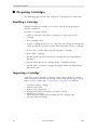
■ Organization
This book contains the following information:
Chapter 1
“General Information” describes the LSM hardware.
Chapter 2
“Controls and Indicators” shows the locations of the power
switch and operator panel and describes the functions of the
softkeys, indicators, and display. This chapter also shows how
to set two configuration options: the DMS (AS/400) host
number and maximum usage count for the cleaning cartridge.
Chapter 3
“Operating the LSM” contains the procedures to operate the
LSM. The procedures include how to display the LSM status,
power on and power off the units, perform automated
operations (enter and remove cartridges through the cartridge
access port), and perform manual operations (load and unload
cartridges).
Chapter 4
“StorageTek Maintenance Support” describes how to contact the
Call Center or Remote Center for assistance if the LSM has a
hardware or software problem.
Appendix A “Cartridge Tape Information” describes how to prepare, inspect,
store, clean, and repair cartridges. It also lists the criteria that
colored cartridges must meet to be used in the LSM.
9504
Glossary
The glossary defines new or special terms and abbreviations
used in this guide.
Index
The Index assists in locating information in this guide.
Sixteenth Edition
xi
Trademarks
■ Trademarks
StorageTek is a trademark of Storage Technology Corporation. Other features
and terms used in this publication are for informational purposes only and
might be trademarks of Storage Technology Corporation or other companies.
■ Alert Messages
Alert messages call the reader’s attention to information that is especially
important or that has a unique relationship to the main text or graphic.
Note: A note provides additional information that is of special interest. A note
might point out exceptions to rules or procedures. A note usually, but
not always, follows the information to which it pertains.
CAUTION:
A caution informs the reader of conditions that might result in damage to
hardware, corruption of data, corruption of application software, or longterm health problems in people. A caution always precedes the
information to which it pertains.
WARNING:
A warning alerts the reader to conditions that might result in injury or
death. A warning always precedes the information to which it pertains.
■ Conventions
Typographical conventions highlight special words, phrases, and actions in this
publication.
Item
Example
Description of Convention
Acronyms
CSA
All uppercase
Buttons
MENU
Sans serif font; capitalization
follows label on product
(usually all uppercase)
Commands
Mode Select
Initial cap
Document titles
System Assurance Guide
Italic font
Emphasis
not or must
Italic font
File names
fsc.txt
Monospace font
Hypertext links
Figure 2-1 on page 2-5
Blue (prints black in hardcopy
publications)
xii
Sixteenth Edition
9504
Related Publications
Item
Example
Description of Convention
Indicators
Open
Italic font; capitalization follows
label on product (usually initial
caps)
Jumper names
TERMPWR
All uppercase
Keyboard keys
<Y>
<Enter> or
<Ctrl+Alt+Delete>
Sans serif font; capitalization
follows label on product
(usually initial caps); enclosed
within angle brackets
Menu names
Configuration Menu
Capitalization follows label on
product; usually title caps
Parameters and variables
Device = xx
Italic font
Path names
c:/mydirectory
Monospace font
Port or connector names
SER1
Capitalization follows label on
product; otherwise, all
uppercase
Positions for circuit
breakers, jumpers, and
switches
ON
Default font; capitalization
follows label on product;
otherwise, all uppercase
Screen text (including
screen captures, screen
messages, and user input)
downloading
Monospace font
Switch names
Power
Sans serif font; capitalization
follows label on product
URLs
http://www.storagetek.com
Blue (prints black in hardcopy
publications)
■ Related Publications
Additional information is contained in the following publications, some of
which are delivered with this product.
DLT Publications
Part Number
Quantum DLT4000 Cartridge Subsystem Product Manual 313127601
(StorageTek)
81-60043-0x
(Quantum)
Quantum DLT7000 Tape Drive Product Manual
9504
Sixteenth Edition
313134501
(StorageTek)
81-60000-0x
(Quantum)
xiii
Additional Information
DLT Publications (Continued)
Part Number
Quantum DLT8000 Tape Drive Product Manual
81-60118-0x
(Quantum)
SDLT Publications
Quantum SuperDLTtape System SDLT 220 Product
Manual
Part Number
81-00000-0x
(Quantum)
9840 Publications
Part Number
9840/T9840 Tape Drive User’s Reference Manual
95739
4890 Publications
Part Number
4890 Maintenance Manual
9512952900
4890 Product Manual
9512941000
IBM Publications
Part Number
Care and Handling of the IBM Magnetic Tape Cartridge
GA32-0047
Tape and Cartridge Requirements for the
IBM 3480 Tape Drive
GA32-0048
ANSI Publications
Part Number
American National Standard Magnetic Tape and
Cartridge for Information Interchange
ACS X3B5
■ Additional Information
StorageTek offers several methods for you to obtain additional information.
Please use one of these methods when you want to obtain the latest edition of
this or any other StorageTek customer publication.
StorageTek’s External Web Site
StorageTek’s external Web site provides marketing, product, event, corporate,
and service information. In addition, the external Web site serves as an entry
point to the Customer Resource Center (CRC) and to the e-Partners site. The
external Web site is accessible to anyone with a Web browser and an Internet
connection.
The URL for the StorageTek external Web site is http://www.storagetek.com
xiv
Sixteenth Edition
9504
Comments and Suggestions
Customer Resource Center
StorageTek’s Customer Resource Center (CRC) is a Web site that enables
members to resolve technical issues by searching code fixes and technical
documentation. CRC membership entitles you to other proactive services, such
as HIPER subscriptions, technical tips, answers to frequently asked questions,
and online product support contact information. Customers who have a current
warranty or a current maintenance service agreement may apply for
membership by clicking on the Request Password button on the CRC home
page.
The URL for the CRC is http://www.support.storagetek.com.
e-Partners Site
StorageTek’s e-Partners site, formerly known as the Partners Page or the
Channels Site, is a Web site that provides information about products, services,
customer support, upcoming events, training programs, and sales tools to
support StorageTek’s e-Partners. Access to this site, beyond the e-Partners Login
page, is restricted. On the e-Partners Login page, current partners who do not
have access can request a login ID and password and prospective partners can
apply to become StorageTek resellers.
The URL for the e-Partners site is http://channels.stortek.com.
Hardcopy Publications
Contact a StorageTek sales or marketing representative to order additional
paper copies of this publication or to order other StorageTek customer
publications in paper format.
■ Comments and Suggestions
A Reader’s Comment Form at the back of this publication lets you communicate
suggestions or requests for change. StorageTek encourages and appreciates
reader feedback.
9504
Sixteenth Edition
xv
Safety Precautions
Safety, Fiber Optic, and ESD
The following pages describe common practices concerning electrical safety,
ergonomics, fiber optics, and electrostatic discharge.
■ Safety Precautions
CAUTION:
Potential injury: On-the-job safety is important; therefore, observe the
following safety precautions while you are engaging in any maintenance
activity. Failing to follow these precautions could result in serious injury.
Remove all conductive jewelry, such as watches and rings, before you
service powered-on equipment.
•
Avoid electrical shock. Be careful when you work near power connectors
and supplies.
•
Power-off the equipment that is being serviced before you remove a field
replaceable unit (FRU) or other component. Remember that dangerous
voltages could still be present in some areas even though power is off.
•
Ground all test equipment and power tools.
•
Lift objects properly; read the information in “Lifting Techniques” (see
below).
•
Do not remove, cut, or relocate any floor tiles indiscriminately. Before you
manipulate floor tiles, be sure that you understand the customer’s
environment and receive the customer’s approval. Remember, each
situation is different.
•
Enforce good housekeeping practices in the equipment area to help prevent
fire and accidents.
Note: Important things to investigate and to be aware of include the use of
Halon® gas, under-the-floor smoke detectors, and cables to other
equipment installed nearby.
xvi
Sixteenth Edition
9504
Safety Precautions
Lifting Techniques
Lifting, regardless of how much or how little, can create serious back stress. If
you follow these guidelines, you can reduce the risk of back injury:
•
Do not twist your body to pick up something or to put it down. Twisting
puts extreme pressure on your back, especially when you lift or carry
objects. Instead of twisting, make the task two separate moves; first lift, and
then use your feet to turn your body.
•
Plan the lift: first examine the object and then determine how it will be
lifted and where it will be placed.
•
Choose the appropriate lifting technique. Examine the weight, size,
location, frequency, and direction of the lift. Plan to avoid awkward
postures, and determine if material-handling aids are needed.
•
Place your feet shoulder-width apart, and place one foot a little behind the
other. Keep your back straight because even light loads can significantly
increase pressure on your spine when you lean forward.
•
Whenever you can, grip the load with your whole hand, and use two
hands.
•
Carry objects at elbow height and close to your body. The farther away you
hold an object, the more force it puts on your lower back.
•
Lift with your legs instead of your back. Leg muscles are some of the
strongest in the body. When you squat and lift with your legs, you can lift
more weight safely.
•
Alternate lifting tasks with tasks that are less stressful to the same muscles.
This technique ensures that your muscles have some recovery time.
Shoulder, Elbow, Wrist, and Hand Safety
Follow these guidelines to minimize the possibility of injury to your shoulders,
elbows, wrists, and hands.
9504
•
Work within your safety zone—the area between shoulder level and
knuckle level of your lowered hands. You face less chance of injury when
you work or lift in this area.
•
Keep your elbows bent to keep loads close to your body and to decrease
the amount of force necessary to do the job. If you use this posture, you
will put less weight and pressure on your shoulder.
Sixteenth Edition
xvii
Fiber Optic Safety
•
Be sure to keep your wrists straight. Avoid bending, extending, or twisting
your wrists for long periods of time.
•
Do not use a pinch grip to lift large or heavy loads because the way you lift
also can affect the tendons in your hand. When you grasp an object
between your thumb and fingers, you put a lot of tension on hand and wrist
tendons. Use both hands—use one for a while, and then use the other—to
give them rest.
■ Fiber Optic Safety
WARNING:
Eye hazard. Never look directly into a fiber-optic cable, a fiber-optic
connector, or a laser transceiver module. Hazardous conditions might
exist from laser power levels that are capable of causing injury to the
eye.
Be especially careful when using optical instruments with this
equipment. Such instruments might increase the likelihood of eye injury.
The laser transceivers in fiber-optic equipment can pose dangers to personal
safety. Ensure that anyone who works with this StorageTek equipment
understands these dangers and follows safety procedures. Ensure that the
optical ports of every laser transceiver module are terminated with an optical
connector, a dust plug, or a cover.
Each fiber-optic interface in this StorageTek Fibre Channel equipment contains
a laser transceiver that is a Class 1 Laser Product. Each laser transceiver has an
output of less than 70 µW and a wavelength of 850 nm. StorageTek’s Class 1
Laser Products comply with EN60825-1(+A-11) and with sections 21 CFR
1040.10 and 1040.11 of the Food and Drug Administration (FDA) regulations.
The following translations are for users in Finland and Sweden who wish to
identify laser safety and classification:
CLASS 1 LASER
LUOKAN 1 LASERLAITE
KLASSE 1 LASER APPARAT
xviii
Sixteenth Edition
9504
Laser Product Label
■ Laser Product Label
In accordance with safety regulations, a label on each StorageTek Fibre Channel
product identifies the laser class of the product and the place and date of the
manufacturer. The label appears on top of a Fibre Channel tape drive and near
the Fibre Channel connectors on a Fibre Channel tape library. A copy of the
label is shown here:
CLASS 1 LASER PRODUCT
LASER KLASSE 1
APPAREIL A LASER DE CLASSE 1
COMPLIES WITH 21 CFR 1040.10 AND 1040.11
■ Fiber-Optic Cable Handling
Observe these precautions when you handle fiber-optic cables:
•
Do not coil the cable to less than 96 mm (3.75 in.) in diameter.
•
Do not bend the cable to less than 12 mm (0.5 in.) in radius. StorageTek
recommends that a cable’s bend radius be no less than 20 times the
diameter of the cable.
•
Do not pull on the cables; carefully place them into position.
•
Do not grasp the cables with pliers, grippers, or side cutters; do not attach
pulling devices to the cables or connectors.
•
Keep cables away from sharp edges or sharp protrusions that could cut or
wear through the cable; make sure that cutouts in the equipment have
protective edging.
•
Protect the cable from extreme temperature conditions.
WARNING:
Eye hazard. Never look directly into a fiber-optic cable, a fiber-optic
connector, or a laser transceiver module. Hazardous conditions might
exist from laser power levels that are capable of causing injury to the
eye.
Be especially careful when using optical instruments with this
equipment. Such instruments might increase the likelihood of eye injury.
•
9504
Install the connector’s protective cover whenever the connector is not
connected.
Sixteenth Edition
xix
Electrostatic Discharge (ESD) Damage Prevention
■ Electrostatic Discharge (ESD) Damage Prevention
Anyone who handles ESD-sensitive components must be aware of the damage
that ESD can cause to electronic components and must take the proper
precautions to prevent it. Also, anyone who performs maintenance on
StorageTek equipment must complete an ESD-basics course.
CAUTION:
Potential damage to equipment: Handle ESD-sensitive components only
under ESD-protected conditions. To meet this requirement, always use
the Field Service Grounding Kit (PN 4711) and always follow these ESD
precautions and procedures when you are servicing StorageTek
equipment or handling ESD-sensitive components.
ESD Precautions
Always take the following general precautions when you work with ESDsensitive components:
•
Wear ESD protection whenever you install, remove, maintain, or repair
StorageTek equipment.
•
Keep ESD-sensitive printed-circuit components in their ESD-protective
packages until you have taken all ESD-preventive steps and you are ready
to install the component.
•
Do not allow anyone to touch or handle an unprotected ESD-sensitive
component unless that person has taken all ESD precautions.
•
Reinstall all equipment covers and close all equipment doors after you have
completed the work.
•
If the grounding-kit work surface has been exposed to temperatures above
66ºC (150ºF) or below 4.5ºC (40ºF), acclimate the work surface to room
temperature before you unroll it.
•
Immediately place any component that you have removed into an ESDprotective package.
•
Keep the grounding-kit work surface clean.
Note: To clean the work surface, use a mild detergent and water, and
make sure that the surface is completely dry before you use it.
•
Periodically check the electrical resistance of the ground cord and the wriststrap coil cord.
Note: The ground cord should measure less than 1.2 MΩ, and the coil
cord should measure between 0.8 and 1.2 MΩ. Repair or replace the
cords if they no longer meet these requirements.
xx
Sixteenth Edition
9504
Electrostatic Discharge (ESD) Damage Prevention
ESD-Protection Procedure
Remember that each customer environment is different. Address all the
customer’s concerns before you work on any equipment.
Prepare the Work Area
1. Before you service the equipment, unfold the grounding-kit work surface
completely and place it on a convenient surface.
2. Attach one end of the ground cord to the work surface; secure the snap
fastener.
Note: You will attach the free end in a later step.
3. Slip on an ESD wrist strap. Make sure that the strap is comfortable and
makes contact with the entire circumference of your wrist.
4. Snap one end of the coil cord to the wrist band.
Access the Equipment
5. Carefully open the doors to the equipment or remove the covers from the
equipment. Do not touch any internal components.
CAUTION:
Be sure that you are properly grounded before you touch any internal
components.
6. Attach the free end of the coil cord to the most appropriate place:
a. If you are working on components from a small piece of equipment,
attach the free end of the coil cord to the grounding-kit work surface. In
addition, be sure that you touch an unpainted metal surface on the
equipment before you touch an internal component.
b. If you are working on components from a large piece of equipment,
attach the free end of the coil cord to a grounding jack or to an
unpainted metal surface inside the equipment.
Replace Components
7. Remove the defective component and place it on the work surface.
8. Remove the replacement component from its ESD-protective package, and
install the component in the equipment.
9. Place the defective component in the ESD-protective package.
9504
Sixteenth Edition
xxi
9710 Interlocks
Clean Up
10. Disconnect the ground cords from the equipment.
11. Reinstall all equipment covers and close all equipment doors.
12. Disconnect the coil cord from your wrist, and, if necessary, disconnect the
ground cord from the work surface.
13. Properly store the work surface and the other Field Service Grounding Kit
items.
■ 9710 Interlocks
Two safety interlocks are provided on the LSM. These interlocks disable drive
current to the LSM motors when either of the two front doors is opened.
1. The door interlock (also referred to as an SPI switch), at the center right of
the LSM frame, generates a software request to turn off drive current to all
LSM motors when the right, front door is opened.
Actuating this switch generates a nonmaskable interrupt (NMI) to the LSM
processor. The processor will allow completion of the current robotic
command before current is disconnected from all LSM motors.
2. The servo power interrupt (SPI) interlock, at the center left of the LSM
frame, generates an immediate hardware disconnection of drive current to
all LSM motors when the left, front door is opened.
Actuating this switch removes all drive current to LSM motors. All robotic
activity comes to an immediate halt.
xxii
Sixteenth Edition
9504
Notices
Please read the following compliance and warning statements for this product.
CAUTION:
Potential equipment damage: Cables that connect peripherals must be
shielded and grounded; refer to cable descriptions in the instruction
manuals. Operation of this equipment with cables that are not shielded
and not correctly grounded might result in interference to radio and TV
reception.
Changes or modifications to this equipment that are not expressly
approved in advance by StorageTek will void the warranty. In addition,
changes or modifications to this equipment might cause it to create
harmful interference.
■ FCC Compliance Statement
The following compliance statement pertains to Federal Communications
Commission Rules 47 CFR 15.105:
Note: This equipment has been tested and found to comply to the limits for
Class A digital devices pursuant to part 15 of the FCC Rules. These limits
are designed to provide reasonable protection against harmful
interference when the equipment is operated in a commercial
environment. This equipment generates, uses, and can radiate radio
frequency energy and, if not installed in accordance with the instruction
manual, may cause harmful interference to radio communications.
Operation of this equipment in a residential area is likely to cause
harmful interference, in which case the user will be required to correct
the interference at his or her own expense.
■ CISPR 22 and EN55022 Warning
This is a Class A product. In a domestic environment, this product may cause
radio interference, in which case, the user may be required to take adequate
measures.
9504
Sixteenth Edition
xxiii
Japanese Compliance Statement
■ Japanese Compliance Statement
The following compliance statement in Japanese pertains to VCCI EMI
regulations:
English translation: This is a Class A product based on the standard of the
Voluntary Control Council for Interference by Information Technology
Equipment (VCCI). If this equipment is used in a domestic environment, radio
disturbance may occur, in which case, the user may be required to take
corrective actions.
■ Taiwan Warning Label Statement
The following warning label statement pertains to BSMI regulations in Taiwan,
R.O.C.:
English translation: This is a Class A product. In a domestic environment, this
product may cause radio interference, in which case, the user may be required
to take adequate measures.
xxiv
Sixteenth Edition
9504
Internal Code License Statement
■ Internal Code License Statement
The following is the Internal Code License Agreement from StorageTek:
NOTICE
INTERNAL CODE LICENSE
PLEASE READ THIS NOTICE CAREFULLY BEFORE INSTALLING AND OPERATING THIS EQUIPMENT. THIS
NOTICE IS A LEGAL AGREEMENT BETWEEN YOU (EITHER AN INDIVIDUAL OR ENTITY), THE END USER, AND
STORAGE TECHNOLOGY CORPORATION (“STORAGETEK”), THE MANUFACTURER OF THE EQUIPMENT. BY
OPENING THE PACKAGE AND ACCEPTING AND USING ANY UNIT OF EQUIPMENT DESCRIBED IN THIS DOCUMENT, YOU AGREE TO BECOME BOUND BY THE TERMS OF THIS AGREEMENT. IF YOU DO NOT AGREE
WITH THE TERMS OF THIS AGREEMENT, DO NOT OPEN THE PACKAGE AND USE THE EQUIPMENT. IF YOU
DO NOT HAVE THE AUTHORITY TO BIND YOUR COMPANY, DO NOT OPEN THE PACKAGE AND USE THE
EQUIPMENT. IF YOU HAVE ANY QUESTIONS, CONTACT THE AUTHORIZED STORAGETEK DISTRIBUTOR OR
RESELLER FROM WHOM YOU ACQUIRED THIS EQUIPMENT. IF THE EQUIPMENT WAS OBTAINED BY YOU
DIRECTLY FROM STORAGETEK, CONTACT YOUR STORAGETEK REPRESENTATIVE.
1.
Definitions: The following terms are defined as
followed:
a.
2.
“Derivative works” are defined as works based
upon one or more preexisting works, such as a
translation or a musical arrangement, or any
other form in which a work may be recast,
transformed, or adapted. A work consisting of
editorial revision, annotations, elaboration, or
other modifications which, as a whole, represent an original work of authorship, is a Deriv- 3.
ative work.
b.
“Internal Code” is Microcode that (i) is an integral part of Equipment, (ii) is required by such
Equipment to perform its data storage and
retrieval functions, and (iii) executes below the
user interface of such Equipment. Internal code
does not include other Microcode or software,
including data files, which may reside or execute in or be used by or in connection with
such Equipment, including, without limitation,
Maintenance Code.
c.
“Maintenance Code” is defined as Microcode
4.
and other software, including data files, which
may reside or execute in or be used by or in
connection with Equipment, and which
detects, records, displays, and/or analyzes malfunctions in the Equipment.
d.
9504
“Microcode” is defined as a set of instructions
(software) that is either imbedded into or is to
be loaded into the Equipment and executes
below the external user interface of such
Equipment. Microcode includes both Internal
Code and Maintenance Code, and may be in
magnetic or other storage media, integrated circuitry, or other media.
The Equipment you have acquired by purchase or
lease is manufactured by or for StorageTek and contains Microcode. By accepting and operating this
Equipment, you acknowledge that StorageTek or its
licensor(s) retain(s) ownership of all Microcode, as
well as all copies thereof, that may execute in or be
used in the operation or servicing of the Equipment
and that such Microcode is copyrighted by StorageTek or its licensor(s).
StorageTek hereby grants you, the end user of the
Equipment, a personal, nontransferable (except as
permitted in the transfer terms in paragraph 7
below), nonexclusive license to use each copy of
the Internal Code (or any replacement provided by
StorageTek or your authorized StorageTek distributor or reseller) which license authorizes you, the
end user, to execute the Internal Code solely to
enable the specific unit of Equipment for which the
copy of Internal Code is provided to perform its
data storage and retrieval functions in accordance
with StorageTek’s (or its licensor’s) official published specifications.
Your license is limited to the use of the Internal
Code as set forth in paragraph 3 above. You may
not use the Internal Code for any other purpose.
You may not, for example, do any of the following:
(i) access, copy, display, print, adapt, alter, modify,
patch, prepare Derivative works of, transfer, or distribute (electronically or otherwise) or otherwise
use the Internal Code;
(ii) reverse assemble, decode, translate, decompile,
or otherwise reverse engineer the Internal Code
(except as decompilation may be expressly permitted under applicable European law solely for the
purpose of gaining information that will allow
Sixteenth Edition
xxv
Internal Code License Statement
interoperability when such information is not otherwise readily available); or
(iii) sublicense, assign, or lease the Internal Code or
permit another person to use such Internal Code, or
any copy of it.
If you need a backup or archival copy of the Internal Code, StorageTek, or your authorized StorageTek distributor or reseller, will make one available
to you, it being acknowledged and agreed that you
have no right to make such a copy.
5.
Nothing in the license set forth in paragraph 3
above or in this entire Notice shall convey, in any
8.
manner, to you any license to or title to or other
right to use any Maintenance code, or any copy of
such Maintenance Code. Maintenance Code and
StorageTek’s service tools and manuals may be kept
at your premises, or they may be supplied with a
unit of Equipment sent to you and/or included on
the same media as Internal Code, but they are to be
used only by StorageTek’s customer service personnel or those of an entity licensed by StorageTek, all
rights in and to such Maintenance Code, service
tools and manuals being reserved by StorageTek or
its licensors. You agree that you shall not use or
attempt to use the Maintenance Code or permit any
other third party to use and access such Maintenance Code.
6.
You, the end user, agree to take all appropriate
steps to ensure that all of your obligations set forth
in this Notice, particularly in paragraphs 4 and 5,
are extended to any third party having access to the
Equipment.
7.
You may transfer possession of the Internal Code to
another party only with the transfer of the Equipment on which its use is authorized, and your
license to use the Internal Code is discontinued
when you are no longer an owner or a rightful possessor of the Equipment. You must give such transferee all copies of the Internal Code for the
transferred Equipment that are in your possession,
along with a copy of all provisions of this Notice.
Any such transfer by you is automatically (without
further action on the part of either party) expressly
xxvi
subject to all the terms and conditions of this Notice
passing in full to the party to whom such Equipment is transferred, and such transferee accepts the
provisions of this license by initial use of the Internal Code. You cannot pass to the transferee of the
Equipment any greater rights than granted under
this Notice, and shall hold StorageTek harmless
from any claim to the contrary by your transferee or
its successors or assigns. In addition, the terms and
conditions of this Notice apply to any copies of
Internal Code now in your possession or use or
which you hereafter acquire from either StorageTek
or another party.
You acknowledge that copies of both Internal Code
and Maintenance Code may be installed on the
Equipment before shipment or included with the
Equipment and other material shipped to you, all
for the convenience of StorageTek’s service personnel or service providers licensed by StorageTek, and
that during the warranty period, if any, associated
with the Equipment, and during periods in which
the Equipment is covered under a maintenance
contract with StorageTek or service providers
licensed by StorageTek, both Internal Code and
Maintenance Code may reside and be executed in
or used in connection with such Equipment, and
you agree that no rights to Maintenance Code are
conferred upon you by such facts. StorageTek or
the licensed service provider may keep Maintenance Code and service tools and manuals on your
premises but they are to be used only by StorageTek’s customer service personnel or those of service providers licensed by StorageTek. You further
agree that upon (i) any termination of such warranty period or maintenance contract period; or (ii)
transfer of possession of the Equipment to another
party, StorageTek and its authorized service providers shall have the right with respect to the affected
Equipment to remove all service tools and manuals
and to remove or disable all Maintenance Code
and/or replace Microcode which includes both
Internal Code and Maintenance Code with Microcode that consists only of Internal Code.
Sixteenth Edition
9504
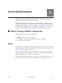
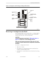
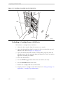
General Information
1
This chapter describes the hardware components of the 9710 library storage
module (LSM). For software information and drive information, refer to the
publications that pertain to these specific topics.
The LSM is the hardware component in an automated tape cartridge system. An
automated cartridge system is a removable media, robotic system that loads
cartridges into a storage cell, into a cartridge access port (CAP), or into a drive
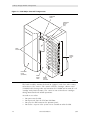
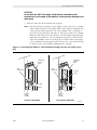
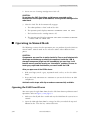
for read/write operations. Figure 1-1 on page 1-2 and Figure 1-2 on page 1-3
show the major components of an LSM, described in the following pages.
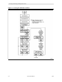
■ Library Storage Module Components
The LSM has four major, internal components:
•
•
•
•
A robot
Storage cells for 224 to 588 cartridges
A cartridge access port (CAP) that holds up to 14 cartridges
Drives (ordered separately)
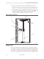
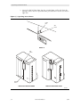
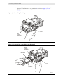
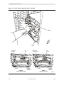
Robot
The robot moves cartridges to storage cells, to a drive, or to the CAP. The robot
consists mainly of the Z column assembly and the hand assembly. Figure 1-2 on
page 1-3 shows the robot components.
The Z column assembly contains a Z column and Z carriage. The Z column
attaches to the floor and ceiling of the LSM. The Z column can rotate almost 360
degrees to allow access to all the cells in the LSM.
The hand assembly mounts to the Z carriage. The Z carriage moves the hand
vertically up and down the Z column to storage cells, drives, or the CAP.
9504
Sixteenth Edition
1-1
Library Storage Module Components
Figure 1-1. LSM Major External Components
OPERATOR
PANEL
CARTRIDGE
ACCESS
PORT
(CAP)
DOOR
LATCHES
DRIVES
(INSIDE
LSM)
EXPANSION
DOOR
(OPTIONAL)
RIGHT
FRONT
DOOR
POWER
SWITCH
LOCATION
C60022
The hand assembly contains the hand (or “gripper”) and a bar code scanner,
referred to as “the camera.” The camera reads the cartridges’ volume serial
(VOLSER) labels during audits and transmits the VOLSER and location of each
cartridge to the LSM’s memory. The camera is not used to locate cartridges
during normal load and unload operations.
An audit occurs when:
•
•
•
•
1-2
You
You
You
You
power on the LSM.
open and close the left front LSM door.
press the IPL button on the operator panel.
make a request at the system server console to audit the LSM.
Sixteenth Edition
9504
Library Storage Module Components
The camera’s functional parameters have two implications for operation:
•
Each time an audit occurs, you must request a host system update from the
system server console. This will add the LSM’s audit data to host memory.
•
If you manually exchange a cartridge from a drive for one in storage, you
must re-IPL (initial program load) the library. Otherwise, host memory will
continue to apply the VOLSER and location information from the first
cartridge to the second cartridge. This might cause an error.
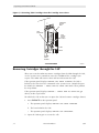
Figure 1-2. Robot Components
Z MOTOR
CAMERA
THETA
MOTOR
HAND
Z COLUMN
Z CARRIAGE
C60183
Storage Cells
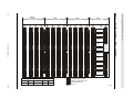
The LSM is configured by panel, column, row and cell so that the customer
server software can locate a cartridge. The LSM contains storage cells for 224 to
588 cartridges, excluding the CAP cells. The number of cells is determined by
how many drives are installed and whether the LSM has the standard left front
door or the expansion door. The expansion frame provides additional storage
9504
Sixteenth Edition
1-3
Library Storage Module Components
space for 168 cartridges. Arrays can be installed above the drives if fewer than
seven drives are installed.
Cartridges are stored in cell arrays that hold 20 cartridges. The cell arrays are
stacked in columns and the columns are arranged in a circle around the robot
assembly. Each column can hold 42 cartridges.
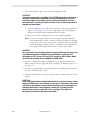
Table 1-1 on page 1-4 lists LSM storage cell capacities. Figure 1-3 on page 1-5,
and Figure 1-4 on page 1-6 show cell locations for an LSM with the base unit,
expansion door, and maximum number of drives installed.
Note: The two cells located next to Drive 4 are designated cleaning cartridge
cells. If you have the AUTO CLEAN feature enabled, you must store
cleaning cartridges in these cells. If you do not, you must leave these
cells empty.
The array targets are used for robotic calibration during IPL.
The CAP and drives are not used to store cartridges.
The empty/drop-off cell is used by the robot to deposit a cartridge that
remains in the hand when a power failure occurs.
CAUTION:
3480-compatible cartridges (for 4890 drives only) must be inserted into
the storage cells with the customer label on top and the VOLSER label
facing the person doing the inserting. If the cartridges are inserted into
the cells upside down, the LSM will stop operating during initialization
(IPL).
Table 1-1. LSM Capacity
Expansion
Frame,
Panel 3
Panels
Available
Drives
Installed
14-Cartridge
Arrays Above
Drives
Total
Cartridges
Yes
0, 1, 2, 3
1 to 3
2
588
4 to 6
1
574
7 to 10
0
560
1 to 3
2
420
4 to 6
1
406
7 to 10
0
392
1 to 3
2
252
4 to 6
1
238
7 to 10
0
224
No
0, 1, 2
1, 2
1-4
Sixteenth Edition
9504
Library Storage Module Components
Figure 1-3. Locating Cartridges—Top View
COLUMN 0
COLUMN 0
PANEL 1
PANEL 2
PANEL 0
PANEL 3
COLUMN 0
COLUMN 0
LSM WITH EXPANSION DOOR
C60035
9504
Sixteenth Edition
1-5
0
0
3
0
0
0
PANEL 1
PANEL 2
COLUMNS
1
2
COLUMNS
1
0
0
3
0
0
0
0
0
3
0
0
0
2
0
0
DRIVE 9
T
T
T
T
T
T
T
T
T
T
T
T
T
T
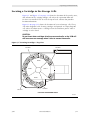
DRIVE 8
DRIVE 7
13
Sixteenth Edition
DRIVE 6
T
T
T
T
T
T
T
T
T
T
T
T
T
DRIVE 5
AREA
RESERVED
FOR
CAP
LATCH
ASSEMBLY
DRIVE 4
DRIVE 3
23
T
DRIVE 2
T
T
T
T
T
T
T
T
T
T
T
T
T
T
DRIVE 1
DRIVE 0
41
41
41
41
41
CUSTOMER CARTRIDGE CAPACITY CHART
DRIVES
BASE
EXPANSION
CAP
TOTAL
10
392
168
14
560
41
41
41
41
41
41
9504
NOT A STORAGE CELL
CLEANING CARTRIDGE CELL
DIAGNOSTIC CARTRIDGE CELL
EMPTY/DROPOFF CELL
CAP CELL
41
41
41
T = ARRAY TARGET
C60148
Library Storage Module Components
0
PANEL 0
COLUMNS
1
2
Figure 1-4. Locating Cartridges—Panels, Cells, Rows
1-6
PANEL 3
(EXPANSION)
COLUMNS
1
2
Library Storage Module Components
Cartridge Access Port
The CAP is the location where you add cartridges to or remove cartridges from
an LSM without interrupting normal cartridge mounts and dismounts. The CAP
is located on the right front door.
If your LSM contains the 14-cartridge CAP array, it must remain in place. You
can insert cartridges into or remove cartridges from the individual cells. If your
LSM contains the 10-cartridge CAP array, you can remove the top screw from
the array, lift out the array, load all the cells, and slide the array back into the
CAP.
Note: The 10-cartridge, removable array is available only for 4890
applications.
You might use the CAP to load and unload cleaning cartridges. Refer to
“Replacing the Cleaning Cartridge” in Chapter 3, “Operating the LSM.” You also
might use the CAP to load and unload data cartridges. For detailed procedures,
refer to, “Entering Cartridges through the CAP” and “Removing Cartridges
through the CAP” in Chapter 3, “Operating the LSM.”
Drives
The robot loads a cartridge into a drive for data read or write operations. The
9710 LSM can contain three types of drives:
•
•
•
•
One
One
One
One
to
to
to
to
six 4890
ten Digital Linear Type (DLT) 4000, 7000 or 8000
ten SDLT BRC (Backward-Read Compatable)
ten 9840/T9840B
The drives are numbered 0 to 9, with 0 at the bottom.
Note: Some software might number the drives from 1 to 10.
An individual LSM may not contain both 9840/T9840B drives and 4890
drives.
During LSM automated mode (see definition at the end of this chapter), the
robotic hand places the cartridge into the drive when a command is sent from
the system server software. During LSM manual mode, you might need to insert
a cartridge into the drive yourself. Refer to “Locating a Cartridge in the Storage
Cells” in Chapter 3, “Operating the LSM,” for the procedure.
For specific drive information, refer to your drive publications.
9504
Sixteenth Edition
1-7
LSM Safety Features
■ LSM Safety Features
Safety features are incorporated into the LSM. If the front doors to the LSM are
opened, electrical interlocks remove power from the robot assembly.
Behind the right front door, covers are placed over the logic card, the AC/DC
power supply, and the power distribution unit (PDU) to prevent you from
coming into contact with hazardous voltages and sensitive electronics.
■ Controlling Software
Controlling software, within the customer server, requests tape read/write
operations to the drives and robotic move operations for the LSM robotic
components. The software determines where the cartridge is located by
tracking the VOLSER and cell location during audits, then allocates which drive
receives the cartridge. For specific information, refer to your software
publications.
When the control path is a direct attachment, the software resides within the
host central processing unit (CPU). When the control path is an indirect
attachment, the software is divided between the server and the host CPUs. For
specific information, refer to your software publications.
■ Library Operating Modes
An operating mode is the manner in which an LSM and the controlling software
(also referred to as the customer server software) interact. An LSM can operate
in either automated mode or manual mode, as described in the subsections
below.
Automated Mode
Automated mode is the normal operating mode of the LSM. The controlling
software instructs the robot to move the cartridge among the storage cells,
drives, and CAP without operator intervention. The operator tasks include:
•
•
•
•
Monitoring the LSM operator display for messages
Entering a cartridge into the CAP
Removing a cartridge through the CAP
Replacing a cleaning cartridge
Refer to Chapter 3, “Operating the LSM,” for the procedures.
1-8
Sixteenth Edition
9504
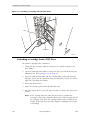
AUTO CLEAN Feature
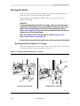
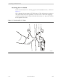
Manual Mode
Manual mode occurs when the LSM is taken offline or loses power. The
operator tasks might include:
•
•
•
•
•
•
•
Opening the LSM front door
Moving the robot
Locating a cartridge
Removing a cartridge from the hand
Loading a cartridge into a drive
Unloading a cartridge from a drive
Returning the LSM to online status
Refer to Chapter 3, “Operating the LSM,” for the procedures.
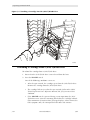
■ AUTO CLEAN Feature
Drives occasionally need to be cleaned to prevent read/write errors.
When your solutions delivery engineer (SDE) configures your LSM during
installation, he/she can enable the AUTO CLEAN feature. If the feature is
enabled and a drive requires cleaning, the robot will receive a software
message telling it to retrieve the cleaning cartridge from the cleaning cell in the
LSM and place it into the drive.
Refer to “Setting Cleaning Cartridge Count” in Chapter 2, “Controls and
Indicators,” and “Replacing the Cleaning Cartridge” in Chapter 3, “Operating the
LSM,” for more information and procedures.
If AUTO CLEAN is not enabled, you must periodically look at the LEDs (lights)
on the drive. When the Use Cleaning Cartridge LED is on, you must place a
cleaning cartridge into the drive. (You might also receive a message at the
system/server console that indicates a drive requires cleaning.)
9504
Sixteenth Edition
1-9
AUTO CLEAN Feature
This page intentionally left blank.
1-10
Sixteenth Edition
9504
Controls and Indicators
2
This chapter shows the locations and describes the functions of the library
storage module (LSM) operator panel and the power switch. It also shows how
to set two configuration options: the DMS host number and the maximum
usage count of the cleaning cartridges. Refer to the drive publications for
information about operating the drives.
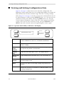
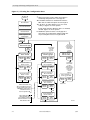
■ Using the Operator Panel
The operator panel is behind the right front door of the LSM. The panel
contains softkeys and indicators, plus a two-line display. The LSM operator
panel shows LSM status, configuration options, diagnostic sequences, and error
information. Figure 2-1 on page 2-2 shows the panel and describes each item.
You use this panel to:
•
Resolve machine problems
If an error occurs, the display shows a fault symptom code (FSC) that you
can give to the solutions delivery engineer (SDE) or to your local service
representative to help resolve problems. Write down the FSC as soon as it is
displayed.
•
Receive the instruction to close the door or cartridge access port (CAP)
•
Set configuration options, such library’s DMS host number and the cleaning
cartridge count
Note: Your SDE configured the library’s SCSI address and entered each
drive’s SCSI address into the operator panel during installation.
These addresses reside in non-volatile memory and are thus
protected during power failures. You should not have to re-enter
these addresses yourself. Contact your SDE if you have concerns
about a SCSI address or if you decide to add more drives to your
LSM.
9504
•
View configuration data
•
Run diagnostic tests
Sixteenth Edition
2-1
Viewing and Setting Configuration Data
■ Viewing and Setting Configuration Data
Figure 2-3 on page 2-4 shows how to view the LSM’s configuration. The
following sections explain how to set two configuration options: the number of
DMS (AS/400) hosts and the maximum usage count for a cleaning cartridge.
Refer to Figure 2-2 on page 2-3 to make sure that you understand how to read
the block diagrams. Usually, pressing EXECUTE means “yes,” that you want to
perform the activity in the block, and pressing MENU means “no,” that you
want to continue through the choices until your activity appears in the block.
Usually, when you are at the end of an activity, you press EXECUTE. Press
MENU if you make a mistake and need to go through the choices again.
Figure 2-1. Operator Panel Softkeys, Indicators, and Display
IPL
SERVICE REQ
(OPERATOR PANEL DISPLAY)
PROCESSOR ACTIVE
INTERFACE ACTIVE
RESET
MENU
EXECUTE
IPL
Initiates the download from the diskette. The IPL sequence
consists of PROM tests, boot tests, and machine initialization.
RESET
DESIGNED FOR CSE USE ONLY! NOT an operator activity.
Initiates a dump.
OPERATOR
PANEL
DISPLAY
Displays machine status and menu information. It also prompts
the operator to perform certain functions.
SERVICE
REQ
Lights when the LSM requires service. The display indicates
PROCESSOR
ACTIVE
Lights solidly until the functional code is active, then flashes on
INTERFACE
ACTIVE
Flashes whenever I/O is performed across a host interface or
Customer Engineer port.
MENU
Accesses SCSI address and cleaning cartridge usage menus and
options.
EXECUTE
Unlocks the CAP and sets SCSI addresses, DMS host number, and
cleaning cartridge usage.
C60005
2-2
Sixteenth Edition
9504
Viewing and Setting Configuration Data
Figure 2-2. Symbol Definitions for Menu Block Diagram
Symbol Definitions for Menu Block Diagrams
Press Execute to
Enter SCSI ID
= display screen with actual display screen text from a top level menu
Press Execute to
Enter 0 as ID
= display screen with actual display screen text
Test Screens
EXECUTE
PRESSED
= display screen and type of information screen is displaying
MENU
PRESSED
bullet ( )
a bullet ( ) plus
a number and a
multiplication symbol
(Example:
3X)
= operator panel softkey operations used in menu sequences
= repeat previous menu action
= the number of times a previous menu action is repeated
between the first and last option in a sequential menu set
How Used....
Press Execute to
Dmnt to Drive 1
EXECUTE
PRESSED
MENU
PRESSED
This configuration
indicates a display
screen and its
softkey options.
PATH
INDICATORS
C60169
9504
Sixteenth Edition
2-3
Viewing and Setting Configuration Data
Figure 2-3. Viewing the Configuration Data
IPL
PRESSED
*
After pressing the execute softkey, there will be a
momentary delay before this screen appears.
Test Screens
*
If the PRW card has been installed instead of the
PRS card, the SCSI host options are 0 through 15.
j
Download BT0.X
Execute BT0.X
If both SCSI and Fibre Channel drives are installed,
do NOT bypass the menu options.
4
Next Sequence of
Tests begin
If all drives are Fibre Channel, press the menu
softkey to bypass the menu options.
Off/On Bus options for drives 1-9 only appear if
those drives are installed and configured and after
the preceding drive has been assigned an ID.
EXECUTE
PRESSED
Press Execute to
*Enter
Frame Type
Press Menu
Until This
Screen
Appears
MENU
PRESSED
Execute to
* Press
Enter SCSI ID
EXECUTE
PRESSED
MENU
PRESSED
Press Execute to
Enter 0 as ID
EXECUTE
PRESSED
MENU
PRESSED
6X
Press Execute to
Enter 7 as ID
EXECUTE
PRESSED
MENU
PRESSED
j Press Execute to
Ent Drv Cfg Info
EXECUTE
PRESSED
When both SCSI and
Fibre Channel drives
are installed, assign an
unused SCSI ID to each
Fibre Channel drive.
2-4
Library Cfg
Cfg is:
is:
Library
Lib Size = XX
X/X
MENU
PRESSED
MENU
PRESSED
4 Press Execute if
Continue to
Press Menu
To View
Each Library
Configuration
Screen and
Until This
Screen
Appears
Drv X Off Bus
EXECUTE
PRESSED
MENU
PRESSED
4 Press Execute if
Drv X On Bus
EXECUTE
PRESSED
MENU
PRESSED
Press Execute if
Drv X is ID 0
When more than one
drive is installed, pressing
execute returns you to the
Off/On Bus menu option
until all drives have
been assigned an ID.
To View
the Library
Configuration
Press Menu
Until This
Screen
Appears
EXECUTE
PRESSED
Press Execute to
Store Cfg in NVR
EXECUTE
PRESSED
MENU
PRESSED
Exit to IPL
MENU
PRESSED
14X
Press Execute if
Drv X is ID 15
EXECUTE
PRESSED
MENU
PRESSED
C60170
Sixteenth Edition
9504
Viewing and Setting Configuration Data
Setting the DMS Host Number
You set the number of DMS (AS/400) hosts from the LSM operator panel. Refer
to Figure 2-2 on page 2-3 and Figure 2-4 on page 2-6 for the menu block
diagrams that describe how to set the DMS host number to one or two hosts.
CAUTION:
During this procedure, the panel displays Press Execute to Enter
Lib Size. This is not normally an operator function. Altering the library
size can cause initialization errors or damage the hand.
9504
Sixteenth Edition
2-5
Viewing and Setting Configuration Data
Figure 2-4. Setting the DMS Host Number
2-6
Sixteenth Edition
9504
Viewing and Setting Configuration Data
Setting Cleaning Cartridge Count
Drives might occasionally need to be cleaned to prevent read/write errors. The
drives are cleaned with a special cleaning cartridge. After a predetermined
number of uses, the cartridge must be thrown away.
If your LSM was configured during installation to have the AUTO CLEAN feature
enabled, you can use the LSM operator panel to set the maximum number of
times a cartridge can be used. The DLT Tape Drive Product Manual suggests
that you use a DLT cleaning cartridge about 20 times. For 4890 cartridges (3840
compatible), refer to the manufacturer’s label to determine the number of times
the cartridge should be used. For 9840/T9840B linear serpentine cartridges,
refer to the 9840/T9840B Tape Drive User’s Reference Manual, PN 95739.
Note: Quantum states that there is not an extensive need for the SDLT
cleaning cartridge due to improved head characteristics of the SDLT 220
over previous generations of DLTtape drives. However, in some highly
stressed environments the cleaning cartridge can be useful. Although
this type of highly stressed environment is not typical, Quantum
believes the differences in customer environments could lead to
situations where cleaning would be beneficial.
The SDLT cleaning tape is in stock and available for order.
Refer to Figure 2-2 on page 2-3 to make sure that you understand how to read
the block diagrams. Refer to Figure 2-5 on page 2-8 for the menu block
diagrams that describe how to set the count.
Note: Use only 3480 compatible cartridges for 4890 drives. Use only DLT
cartridges for DLT drives. Use only SDLT cartridges for SDLT drives. Use
only 9840/T9840B cartridges for 9840/T9840B drives
9504
Sixteenth Edition
2-7
Viewing and Setting Configuration Data
Figure 2-5. Setting the Maximum Usage Count of the Cleaning Cartridge
Online Cap
Unlk Disabld
MENU
PRESSED
Limit = XXX
* 9840
Count = XXX
Press Execute to
Change Limit
MENU
PRESSED
MENU
PRESSED
EXECUTE
PRESSED
EXECUTE
PRESSED
Execute to
*Press
Show 9840 Data
j
EXECUTE
PRESSED
EXECUTE
PRESSED
MENU
PRESSED
Execute to
*Press
Show DLT Data
MENU
PRESSED
EXECUTE
PRESSED
MENU
PRESSED
Press Execute to
Exit Menu
MENU
PRESSED
EXECUTE
PRESSED
MENU
PRESSED
MENU
PRESSED
Press Execute to
Set to 100
MENU
PRESSED
19X
Press Execute to
Set to 1
EXECUTE
PRESSED
MENU
PRESSED
Online - Press
Exe to Unlk CAP
LSM is configured for DLTs or 4890s only, the DLT or 3480 screen option
* Ifwilltheappear
instead of 9840.
the LSM is configured for a mixed environment, both the 9840 (or 3480) and
* IfDLT
menu options are available. Use the menu button to access the other option.
j
9840 limits decrease from 100 to 1 in decrements of 5; DLT from 20 to 1 in
C60287
2-8
Sixteenth Edition
9504
Locating the LSM’s Power Switches
■ Locating the LSM’s Power Switches
The power switch is a circuit breaker located in the lower right corner of the
right front door of the LSM.
Two configurations of power switches exist:
•
A single switch located on the AC power supply controls the LSM and up to
six drives.
•
An additional switch located on the optional power distribution unit (PDU)
controls up to four additional drives. For this configuration, the two
switches are connected by a gang bracket.
To supply power to the LSM and/or optional PDU, lift the switches or switch.
To remove power from the LSM and drives, make sure that all jobs being
performed are complete. Then Push down the single switch or gang bracket.
The robot and all drives power-off completely. Figure 2-6 on page 2-10 shows
the power switch location.
9504
Sixteenth Edition
2-9
Locating the LSM’s Power Switches
Figure 2-6. Power Switch Location
POWER
SWITCH
DETAIL A
AC/DC POWER SUPPLY ONLY
A,B
POWER
SWITCHES
DETAIL B
WITH OPTIONAL PDU
C60155
2-10
Sixteenth Edition
9504
Operating the LSM
3
This chapter contains the procedures for:
•
•
•
•
•
Powering on the LSM
Powering off the LSM
IPLing the LSM
Operating in automated mode
Operating in manual mode
Note: When the machine is controlled by the host, refer to your software
publications and enter the command at the system/server console to
perform the desired activity. For some activities, you might have to ask
your systems administrator for the required information.
■ Powering on or IPLing the LSM
To power on the LSM, lift the single power switch or gang bracket located on
the bottom right corner of the right front door of the LSM. The LSM will
automatically begin an initial program load (IPL) sequence.
Note: If the LSM does not power on, contact StorageTek’s Call Center and
report the problem.
To re-IPL the LSM after it is already powered-on, press the IPL soft key located
on the operator panel.
■ Powering off the LSM
To power off the LSM:
1. Enter the command at the system/server console to remove the LSM and
drives from online status.
2. Push down the single power switch or gang bracket located on the bottom
right corner of the right front door of the LSM.
■ Operating in Automated Mode
Automated mode is the normal operating mode of the LSM. When the LSM is
online and the robot is loading and unloading cartridges, monitor your system/
server console and the LSM operator panel for messages and respond
appropriately.
9504
Sixteenth Edition
3-1
Operating in Automated Mode
When an LSM is online, you might need to:
•
•
•
Enter cartridges into the LSM through the cartridge access port (CAP)
Remove cartridges from the LSM through the CAP
Replace a cleaning cartridge
The following text describes how to perform these activities.
Entering Cartridges through the CAP
If the operator panel displays ONLINE CAP UNLK DISABLD, the CAP is
locked by the host.
Issue the command at the customer server console to allow the CAP to be
unlocked. Then perform the steps below.
If the operator panel displays ONLINE – PRESS EXE TO UNLK CAP, go
directly to the steps below.
To unlock the CAP so that you can open the CAP and enter cartridges into it,
examine Figure 3-1 on page 3-3 and Figure 3-2 on page 3-4 and follow these
steps:
1. Press EXECUTE on the operator panel.
a. The operator panel displays ONLINE CAP UNLK PENDING.
b. The robot hand unlocks the CAP.
c. The operator panel displays ONLINE CAP UNLOCKED.
CAUTION:
You must enter the cartridges properly or you might damage the robot or
the drive, or cause the LSM to stop operating. Use only 3480-compatible
cartridges for the 4890 drives. Use only DLT cartridges for the DLT
drives. Use only SDLT media for SDLT drives. Use only 9840/T9840B
linear serpentine cartridges for 9840/T9840B drives.
2. Open the CAP to gain access to the cells.
3. Enter the cartridges:
a. Place the cartridges in the 14-cartridge fixed array so that they lie flat,
with the customer label on top and the tape leader block cutout on the
right-hand side, or
b. Insert the cartridges into the removable CAP array and insert the array
into the CAP. Make sure that the cartridges are properly oriented and
properly seated.
3-2
Sixteenth Edition
9504
Operating in Automated Mode
CAUTION:
Do not slam the CAP. Cartridges could become unseated and be
extended out into the path of the robotics, causing severe damage to the
robot hand.
4. Close the CAP. The lock automatically engages.
Note: The host software determines what happens when you enter a cartridge
upside down or with an unreadable label. Under normal conditions, the
camera on the hand audits the CAP and recognizes that a cartridge is
present, but the hand does not move it. You must remove the cartridge
from the CAP. With some host software, the LSM might stop operating.
With other host software, you are prompted to type in a label number
when no VOLSER is read. If you do type in a label number, this might
cause a problem later during an audit, because the camera still will not
be able to read an unreadable VOLSER on the cartridge.
Figure 3-1. Entering DLT, SDLT or 9840/T9840B Cartridges into the Cartridge Access
Port
CARTRIDGE
ACCESS
PORT
CARTRIDGE
ACCESS
PORT
TAPE
CARTRIDGE
TAPE
CARTRIDGE
VOLUME
SERIAL
NUMBER
ACCESS
DOOR
VOLUME
SERIAL
NUMBER
DLT/SDLT CARTRIDGE
9840/T9840B CARTRIDGE
C60031
9504
Sixteenth Edition
3-3
Operating in Automated Mode
Figure 3-2. Entering 3480 Cartridges into the Cartridge Access Port
CARTRIDGE
ACCESS
PORT
TAPE
CARTRIDGE
TAPE
LEADER
BLOCK
CUTOUT
VOLUME
SERIAL
NUMBER
3480 CARTRIDGE
C60549
Removing Cartridges through the CAP
When you want the robot to remove cartridges from the LSM through the CAP,
use the system/server console to enter the VOLSERs of the cartridges you
require. The robot will retrieve them and insert them into the CAP.
If the operator panel displays ONLINE CAP UNLK DISABLD, the CAP is
locked by the host. Issue the command at the system/server console that puts
the LSM in the ONLINE – PRESS EXE TO UNLK CAP mode. Then perform
the steps below.
If the operator panel displays ONLINE – PRESS EXE TO UNLK CAP, go
directly to the steps below.
To unlock the CAP so that you can open the CAP and remove cartridges from it:
1. Press EXECUTE on the operator panel.
a. The operator panel displays ONLINE CAP UNLK PENDING.
b. The hand unlocks the CAP.
c. The operator panel displays ONLINE CAP UNLOCKED.
2. Open the CAP to gain access to the cells.
3-4
Sixteenth Edition
9504
Operating in Automated Mode
3. Remove the cartridges and store them outside the LSM (refer to “Storing
Cartridges” in Appendix A, “Cartridge Tape Information”) or
4. Remove the array from the CAP, remove the cartridges from the array, and
store the cartridges outside the LSM (refer to “Storing Cartridges” in
Appendix A, “Cartridge Tape Information”).
CAUTION:
Do not slam the CAP. Cartridges could become unseated and be
extended out into the path of the robotics, causing severe damage to the
robot hand.
5. Close the CAP. The lock automatically engages.
6. Repeat these steps until all the desired cartridges have been removed.
Replacing the Cleaning Cartridge
Cleaning cartridges clean the drive and thus prevent read and write errors. The
following paragraphs pertain to you if your LSM has the AUTO CLEAN feature
enabled. You can use the View Configuration section of Figure 2-3 on page 2-4
to determine whether the feature is enabled.
If the feature is not enabled, you will need to keep track of how many times a
cleaning cartridge has been used, and throw it away when necessary.
When a cleaning cartridge has been used a number of times, as defined in
“Setting Cleaning Cartridge Count” in Chapter 2, “Controls and Indicators,” the
LSM operator panel displays (3480, DLT, or 9840) CLEANING
CARTRIDGE USED UP. You must remove the expired cartridge and place a
new cartridge into the CAP. If your machine has AUTO CLEAN enabled, use the
procedures in the following sections to replace the cartridge.
Note: The DLT Tape Drive Product Manual recommends using a cleaning
cartridge about 20 times. For the 3480-compatible cartridge, refer to the
manufacturer’s label on the cartridge to determine the number of uses.
For the 9840/T9840B cartridge, refer to the 9840/T9840B User’s
Reference Manual, PN 95739.
Quantum states that there is not an extensive need for the SDLT
cleaning cartridge due to improved head characteristics of the SDLT 220
over previous generations of DLTtape drives. However, in some highly
stressed environments the cleaning cartridge can be useful. Although
this type of highly stressed environment is not typical, Quantum
believes the differences in customer environments could lead to
situations where cleaning would be beneficial.
The SDLT cleaning tape is in stock and available for order.
9504
Sixteenth Edition
3-5
Operating in Automated Mode
Cleaning cartridges have a VOLSER prefix of DG CLN or CLNxxx. These
cartridges cannot be used as scratch cartridges or initialized by software utilities.
Use the LSM operator panel and the CAP to remove the expired cleaning
cartridge from the LSM and replace it with a new cleaning cartridge.
CAUTION:
Do not re-enter a cleaning cartridge that has been ejected from an LSM.
When you enter a cleaning cartridge, the software considers it to be new
and sets the usage counter to zero.
To replace the expired cleaning cartridge:
1. Press MENU until the LSM operator panel displays PRESS EXECUTE TO
REPLACE CLN CART.
2. Press EXECUTE. The panel displays PRESS EXECUTE TO REPLACE
3480 CART.
3. To replace the 3480-compatible cleaning cartridge, press EXECUTE and
wait until the CAP unlocks. Go to Step 6.
4. To replace the DLT or SDLT cleaning cartridge, press MENU.
The LSM operator panel displays PRESS EXECUTE TO REPLACE DLT
CART.
Press EXECUTE and wait until the CAP unlocks.
a. The hand takes the expired cleaning cartridge from its cell inside the
LSM and inserts it into the CAP.
b. The hand unlocks the CAP.
c. Go to Step 6.
5. To replace the 9840/T9840B cleaning cartridge, press MENU.
The LSM operator panel displays PRESS EXECUTE TO REPLACE 9840
CART.
Press EXECUTE and wait until the CAP unlocks.
a. The hand takes the expired cleaning cartridge from its cell inside the
LSM and inserts it into the CAP.
b. The hand unlocks the CAP.
c. Go to Step 6.
6. Open the CAP and remove the expired cartridge.
7. Throw away the expired cartridge.
3-6
Sixteenth Edition
9504
Operating in Manual Mode
8. Insert one new cleaning cartridge into a CAP cell.
CAUTION:
Do not slam the CAP. Cartridges could become unseated and be
extended out into the path of the robotics, causing severe damage to the
robot hand.
9. Close the CAP. The lock automatically engages.
a. The robot performs a brief audit of the CAP.
b. The operator panel displays MOVING CLEANING CART TO CELL.
c. The hand inserts the cartridge into its cell.
d. The operator panel displays ONLINE CAP UNLK DISABLD or ONLINE
– PRESS EXE TO UNLK CAP.
■ Operating in Manual Mode
The following sections describe operations you can perform when the LSM is in
manual mode. Manual mode occurs when the LSM is either offline or loses
power.
CAUTION:
Components are sensitive to static electricity. Even a small electrostatic
discharge could damage an electrical component inside the LSM. A
damaged component might not fail immediately, but over time, it will
become worse, possibly causing an “intermittent” problem. Be sure to
touch gray, unpainted metal before you reach inside the LSM.
After you open one of the LSM’s doors:
1. With your finger, touch a gray, unpainted metal surface, such as the LSM’s
frame.
2. Keep your body movement to a minimum as you touch the drives or LSM
components
Antistatic wrist straps with clip-on ends are commercially available.
Opening the LSM Front Doors
You must open the right front door, then the left front door to perform manual
operations. Refer to Figure 3-3 on page 3-8.
1. Make sure that all jobs have ended and vary the LSM from the system/server
console.
2. Open the LSM right front door by using a latch key to unlock the top and
bottom latches. Turn the key counterclockwise.
9504
Sixteenth Edition
3-7
Operating in Manual Mode
3. Open the LSM left front door. For the standard door, pull gently from the
top right corner. For the expansion door, pull from the recessed area on the
right side.
Figure 3-3. Opening Access Doors
LATCH
KEY
TOP
LATCH
DETAIL A
TOP
LATCH
A
BOTTOM
LATCH
LSM WITH EXPANDED DOOR
LSM WITH STANDARD DOOR
C60032
3-8
Sixteenth Edition
9504
Operating in Manual Mode
Moving the Robot
After you open the LSM doors, you might need to move the robot to make it
easier to access the stored cartridges or the drives.
Read and observe the following caution before you attempt to move any
portion of the robot.
CAUTION:
To prevent damaging the hand or Z carriage, make sure that the reach
mechanism on the hand is fully retracted before moving any part of the
robot. Turn the hand pulley to retract the reach mechanism (refer to
Figure 3-9 on page 3-14). If you fail to retract the hand before the robot is
rotated, the hand will be damaged.
Move the Z column and Z carriage only as shown in Figure 3-4 on
page 3-9 and Figure 3-5 on page 3-10.
Do not touch exposed electrical parts when moving any part of the robot.
Raising and Lowering the Z Carriage
If you need to raise or lower the hand, slowly and carefully move it by placing
your fingers on the Z carriage as shown in Figure 3-4.
Figure 3-4. Raising and Lowering the Z Carriage
LOWERING THE Z CARRIAGE
RAISING THE Z CARRIAGE
E60033
9504
Sixteenth Edition
3-9
Operating in Manual Mode
Rotating the Z Column
If you need to rotate the Z column, grasp it and carefully rotate it, as shown in
Figure 3-5.
The Z column does not rotate a full 360 degrees. If the column meets resistance
and stops before the desired position is reached, it has contacted a stopping
mechanism mounted on the floor of the LSM. Do not force it. Rotate the column
in the opposite direction.
Figure 3-5. Rotating the Z Column
E60034
3-10
Sixteenth Edition
9504
Operating in Manual Mode
Locating a Cartridge in the Storage Cells
Figure 3-6 and Figure 3-7 on page 3-12 show the locations of the panels, rows,
and columns of the cartridge storage cells when the expansion door and
10 drives are installed. The decal at the top of each column also provides
location information.
Figure 3-8 on page 3-13 shows the locations of reserved storage cells. These
cells store diagnostic and cleaning cartridges and provide an empty/drop-off
cell, where the robot inserts a cartridge when the LSM loses power while a
cartridge is in the hand.
CAUTION:
Do not insert data cartridges into these reserved cells, or the LSM will
will issue an error message when it tries to access these cells.
Figure 3-6. Locating Cartridges—Top View
COLUMN 0
COLUMN 0
PANEL 1
PANEL 2
PANEL 0
PANEL 3
COLUMN 0
COLUMN 0
LSM WITH EXPANSION DOOR
C60035
9504
Sixteenth Edition
3-11
0
0
3
0
0
0
PANEL 1
PANEL 2
COLUMNS
1
2
COLUMNS
1
0
0
3
0
0
0
0
0
3
0
0
0
2
0
0
DRIVE 9
T
T
T
T
T
T
T
T
T
T
T
T
T
T
DRIVE 8
DRIVE 7
13
Sixteenth Edition
DRIVE 6
T
T
T
T
T
T
T
T
T
T
T
T
T
DRIVE 5
AREA
RESERVED
FOR
CAP
LATCH
ASSEMBLY
DRIVE 4
DRIVE 3
23
T
DRIVE 2
T
T
T
T
T
T
T
T
T
T
T
T
T
T
DRIVE 1
DRIVE 0
41
41
41
41
41
CUSTOMER CARTRIDGE CAPACITY CHART
DRIVES
BASE
EXPANSION
CAP
TOTAL
10
392
168
14
560
41
41
41
41
41
41
9504
NOT A STORAGE CELL
CLEANING CARTRIDGE CELL
DIAGNOSTIC CARTRIDGE CELL
EMPTY/DROPOFF CELL
CAP CELL
41
41
41
T = ARRAY TARGET
C60148
Operating in Manual Mode
0
PANEL 0
COLUMNS
1
2
Figure 3-7. Locating Cartridges—Panels, Cells, Rows
3-12
PANEL 3
(EXPANSION)
COLUMNS
1
2
Operating in Manual Mode
Figure 3-8. Diagnostic and Cleaning Cartridge Cell Locations
CALIBRATION
BLOCK
NOT TO BE USED
(ROW 22)
9840/T9840B OR 3480
CLEANING CARTRIDGE
(ROW 23)
DLT/SDLT
CLEANING CARTRIDGE
(ROW 24)
9840/T9840B OR 3480
DIAGNOSTIC CARTRIDGE
(ROW 25)
DLT/SDLT
DIAGNOSTIC CARTRIDGE
(ROW 26)
DRIVE 2
EMPTY/
DROPOFF
CELL
(ROW 27)
DRIVE 1
DRIVE 0
PANEL 2
COLUMN 2
C60186
Removing a Cartridge from the Hand
If the LSM goes offline due to a power failure, a cartridge might be
left in the hand. You can remove it from the hand and manually
mount it into a drive for a read/write operation.
CAUTION:
Follow the procedures described in “Moving the Robot” on
page 3-9. Failing to do so could damage the hand.
Make sure that you do not touch the TWH card on the hand
assembly. It contains ESD-sensitive components and could be
damaged.
To remove a cartridge from the hand:
1. Rotate the Z column:
9504
•
If the LSM has an expansion door, move the hand until it is
facing the expansion door location.
•
If the LSM has a standard door, move the hand until it is facing
the door.
Sixteenth Edition
3-13
Operating in Manual Mode
2. Rotate the hand pulley (as shown in Figure 3-9 on page 3-14) until the
gripper is extended to its full position, as shown in Figure 3-10 on
page 3-14.
Figure 3-9. Extending the Gripper
HAND
PULLEY
TAPE
CARTRIDGE
(SHOWN
RETRACTED)
C60037
Figure 3-10. Removing a Cartridge from the Hand
REACH
MECHANISM
(SHOWN
EXTENDED)
GRIPPER
MECHANISM
HAND
PULLEY
TAPE
CARTRIDGE
C60036
3-14
Sixteenth Edition
9504
Operating in Manual Mode
3. Hold the hand pulley with one hand and grasp the cartridge with the other.
Pull gently on the cartridge until it is released from the gripper, as shown in
Figure 3-10.
CAUTION:
Make sure that the gripper mechanism is fully retracted. If it is left
extended and you turn the robot, the gripper mechanism will strike a
storage cell. If it is left extended and the hand is facing the LSM door
when it is closed, the door will strike the gripper mechanism.
4. Turn the hand pulley until the gripper mechanism is fully retracted.
Loading a Cartridge into a 4890 Drive
To load a cartridge into a 4890 drive:
1. Obtain the cartridge VOLSER, location, and drive number from the system/
server console.
2. Open the LSM right front door by using a latch key to unlock the top and
bottom latches. Refer to Figure 3-3 on page 3-8.
3. Open the LSM left front door. For the standard door, pull gently from the
top right corner. For the expansion door, pull from the recessed area on the
right side. Take ESD precautions.
4. Locate the cartridge.
WARNING:
Keep your fingers out of the drive when loading a cartridge; the drive
elevator lowers automatically.
5. If necessary, remove the cartridge from a previous job and place it outside
the LSM.
CAUTION:
You must insert the cartridge properly or you will damage the drive. Use
only 3480-compatible cartridges for the 4890 drives. Use only DLT
cartridges for the DLT drives. Use only SDLT media for the SDLT drives.
Use only linear serpentine cartridges for 9840/T9840B drives. Make sure
that the cartridge has a readable VOLSER label.
6. Insert the cartridge as shown in Figure 3-11.
Note: If a 4890 drive has been running, it might not accept the tape unless you
place the drive into manual mode. Press the READY button on the drive
panel to turn the Ready light off. Press the UNLOAD button to reset the
carriage on the drive to allow the drive to be loaded in manual mode.
9504
Sixteenth Edition
3-15
Operating in Manual Mode
Figure 3-11. Loading a Cartridge into the 4890 Drive
DRIVE
CARTRIDGE
E60038
Unloading a Cartridge from a 4890 Drive
To dismount a cartridge from a 4890 drive:
1. Obtain the drive number from the system/server console.
2. Open the LSM right front door by using a latch key to unlock the top and
bottom latches. Refer to Figure 3-3 on page 3-8.
3. Open the LSM left front door. For the standard door, pull gently from the
top right corner. For the expansion door, pull from the recessed area on the
right side. Take ESD precautions.
4. Locate the desired drive.
5. Press the READY toggle button on the drive to make it not ready.
6. Press the UNLOAD button on the drive.
7. Remove the cartridge from the raised elevator.
8. Properly store the cartridge outside the LSM (refer to “Storing Cartridges” in
Appendix A, “Cartridge Tape Information”).
3-16
Sixteenth Edition
9504
Operating in Manual Mode
Loading a Cartridge into a DLT Drive
CAUTION:
Do not attempt to operate a DLT drive’s shuttle mechanism until you see
the Operate Handle indicator light. The indicator will not light until the
drive has completed initialization (about 10 seconds).
To load a cartridge into a DLT drive:
1. Obtain the cartridge VOLSER, location and drive number from the system/
server console.
2. Open the LSM right front door by using a latch key to unlock the top and
bottom latches. Refer to Figure 3-3 on page 3-8.
3. Open the LSM left front door. For the standard door, pull gently from the
top right corner. For the expansion door, pull from the recessed area on the
right side. Take ESD precautions.
4. Locate the cartridge.
5. Make sure that the DLT handle is up and the cartridge hook and hub are
down. Figure 3-12 on page 3-18 shows these positions.
9504
Sixteenth Edition
3-17
Operating in Manual Mode
Figure 3-12. DLT Shuttle, Handle, Hook, and Hub
A,B
DRIVE
SHUTTLE
DLT
DRIVE
HUB
(UP)
CARTRIDGE
HOOK (UP)
HANDLE
VIEW A
CARTRIDGE
HOOK (DOWN)
OPERATE
HANDLE
INDICATOR
HANDLE DOWN POSITION
HUB
(DOWN)
HANDLE
VIEW B
OPERATE
HANDLE
INDICATOR
HANDLE UP POSITION
E60438
3-18
Sixteenth Edition
9504
Operating in Manual Mode
6. If the DLT handle is down, raise it by operating the shuttle:
CAUTION:
Potential damage to the cartridge: The DLT7000 drive does not release a
cartridge’s tape leader immediately. So when attempting to raise the
handle (and eject a cartridge), you must hold the shuttle in for three
seconds before releasing it. Failure to hold in the shuttle could result in
damage the tape leader.
a. Push the shuttle back (see the direction of the arrow in the top half of
Figure 3-12 on page 3-18). If you are operating a DLT7000, hold the
shuttle in the pushed back position for three seconds.
b. Release the shuttle, allowing it to return to its normal position.
Note: If you use this procedure to raise the handle when the Operate
Handle indicator is not lit, a safety mechanism will prevent damage
to the drive. To reset the mechanism, wait for the Operator Handle
indicator to light. Push the shuttle in completely; then pull firmly on
the shuttle. If the handle does not raise, repeat these actions.
CAUTION:
You must insert the cartridge properly or you will damage the drive. Use
only 3480-compatible cartridges for the 4890 drives. Use only DLT
cartridges for DLT drives. Use only SDLT media for SDLT drives. Make
sure that the cartridge has a readable VOLSER label.
7. Hold the cartridge so that the VOLSER label is facing you and the write
protect switch is on the right side of the cartridge, as shown in Figure 3-13
on page 3-20.
8. Insert the cartridge into the shuttle and push the cartridge into the back of
the drive until it is firmly seated.
9. Push the shuttle all the way back, pause for three seconds, then release the
shuttle.
CAUTION:
If the cartridge has been ejected from the drive, you must remove it from
the shuttle before you can reload it into the drive. Otherwise, the shuttle
will become jammed by simultaneously holding onto the cartridge and
lowering the handle. If this happens, release the cartridge from the
shuttle latch under the right side of the cartridge. Then push the
cartridge into the drive and lower the handle.
9504
Sixteenth Edition
3-19
Operating in Manual Mode
Figure 3-13. Loading a Cartridge into the DLT Drive
DRIVE
CARTRIDGE
E60374
Unloading a Cartridge from a DLT Drive
To unload a cartridge from a DLT drive:
1. Obtain the drive number from the system/server console and place the
drive offline.
2. Open the LSM right front door by using a latch key to unlock the top and
bottom latches. Refer to Figure 3-3 on page 3-8.
3. Open the LSM left front door. For the standard door, pull gently from the
top right corner. For the expansion door, pull from the recessed area on the
right side. Take ESD precautions
4. Locate the desired drive.
5. Make sure that the Operate Handle indicator is on.
6. Push the shuttle all the way back, pause for three seconds, then release the
shuttle.
Note: If the cartridge does not come out of the drive, remount the
cartridge by releasing it from the shuttle latch under the right side of
the cartridge. Then push the cartridge into the drive and lower the
handle. If this fails, the tape leader might be dislodged and require
re threading.
3-20
Sixteenth Edition
9504
Operating in Manual Mode
7. Remove the cartridge from drive.
8. Store the cartridge outside the LSM (refer to “Storing Cartridges” in
Appendix A, “Cartridge Tape Information”).
Loading a Cartridge into a 9840/T9840B Drive
To load the cartridge in a 9840/T9840 drive:
1. Insert the cartridge into the 9840/T9840 drive using the direction shown in
Figure 3-14 on page 3-22.
2. Wait for one of the following messages to display and take the appropriate
action, if necessary:
9504
•
The Ready F (File Protected) message displays when a write-protected
cartridge loads successfully.
•
The Ready U (File Unprotected) message displays when a cartridge
that is not write-protected loads successfully.
•
The NTReady message displays when the tape in the cartridge has lost
tension. Follow the instructions outlined in the 9840/T9840 Tape Drive
User’s Reference Manual, PN 95739 to correct this condition.
•
The LOADxxxx message displays when the cartridge unsuccessfully
loads, where the xxxx is a fault symptom code. Follow the instructions
outlined in PN 95739 to correct this condition.
Sixteenth Edition
3-21
Operating in Manual Mode
Figure 3-14. Loading a Cartridge into the 9840/T9840B Drive
C60489
Unloading a Cartridge from a 9840/T9840B Drive
To unload the cartridge from a 9840/T9840 drive:
1. Ensure that the 9840/T9840 drive is not selected from the host.
2. Press the UNLOAD switch.
One of the following conditions can occur:
3-22
•
After the tape rewinds, the cartridge ejects from the 9840/T9840 drive.
Remove the cartridge from the 9840/T9840 drive.
•
The cartridge fails to eject after the tape rewinds. Refer to the 9840/
T9840 Tape Drive User’s Reference Manual, PN 95739 to correct this
condition.
•
If the UNLOAD switch is pressed during a write operation, the 9840/
T9840 drive tries write the remaining data before the cartridge unloads.
If the UnWrxxxx (Unwritten Data) message displays, where xxxx is the
fault symptom code, the attempt failed and some data remains
Sixteenth Edition
9504
Operating in Manual Mode
unwritten to the tape. For more information about recovering from an
Unwritten Data condition, refer to PN 95739.
Returning the LSM to Online Status
To place the LSM online for automated operations:
1. Refer to your specific drive publications for instructions on making the
drives ready. For DLT or SDLT, make sure that the Operate Handle light is
on and the handle is up.
2. Close and lock the LSM doors. The robot will perform an LSM audit of the
cells.
3. Place the LSM online by entering the command at the system/server
operator console.
4. Refer to your specific software publications for instructions on placing the
cartridges you removed into the CAP and having the robot insert the
cartridges into the LSM cells.
9504
Sixteenth Edition
3-23
Operating in Manual Mode
This page intentionally left blank.
3-24
Sixteenth Edition
9504
StorageTek Maintenance Support
4
This chapter describes what to do if problems occur with the LSM. In some
cases, you might be able to correct the problem. In other cases, you must
contact your service representative, as described in this chapter.
When the problem is caused by cartridge tapes, refer to Appendix A, “Cartridge
Tape Information.” When the problem is caused by cartridge tape units, refer to
your drive unit operator’s guide.
Most of the time, a fault symptom code (FSC) will appear on the LSM operator
panel display. Write down the information on the display as soon as it appears,
and give the information to your customer representative or to the staff at the
StorageTek Call Center.
■ StorageTek Call Center
The StorageTek Call Center is available 24 hours a day, seven days a week, to
customers with StorageTek maintenance contracts and to StorageTek solutions
delivery engineers (SDEs).
■ Customer Initiated Maintenance (CIM)
Customer Initiated Maintenance begins with a telephone call from a customer to
the StorageTek Call Center. You receive immediate attention from StorageTek
personnel, who record problem information and respond in one of two ways:
•
•
Route your call to the Remote Center. Trained hardware support personnel
will then help you resolve the problem over the phone.
Dispatch a local SDE to your site.
To contact the Call Center about a problem:
1. Use the telephone to call the StorageTek central dispatcher at
☎ 1–800–525–0369.
9504
Sixteenth Edition
4-1
Customer Initiated Maintenance (CIM)
2. Tell the central dispatcher why you are calling. The central dispatcher will
ask several questions and take the appropriate response. If you have
answers to the following questions ready when placing a service call, the
process is much smoother and faster:
Site location number _________________
Account name _______________________
Equipment model number _____________
Contact name ________________________
Telephone number ____________________
Problem description ___________________
Urgency of problem ___________________
4-2
Sixteenth Edition
9504
Cartridge Tape Information
A
This appendix describes how to prepare, inspect, store, clean, and repair
cartridges. It also lists cartridge specifications.
■ Basic Requirements for Cartridges
LSM cartridges must meet specifications defined in, American National
Standard Magnetic Tape & Cartridge for Information Interchange, ACS X3B5.
Cartridges must meet the following requirements:
•
Cartridges
-
•
Media
-
•
105.6 mm x 105.3 mm x 25.4 mm (4.16 in. x 4.15in. x 1 in.)
Integrated thumbwheel
Chromium dioxide
12.7 mm (0.5 in.) wide
165 m (541 ft) long minimum
No beginning of tape/end of tape reflective markers
Volume serial number (VOLSER) label
-
Valid characters are A–Z, 0–9, # (crosshatch), or trailing blanks. Leading
blanks are not allowed.
■ Colored Cartridge Specifications
Colored cartridges are approved only if the measured reflection density is
greater than 1.20 for DLT cartridges and 1.50 for 9840/T9840B cartridges, as
measured by an X-Rite 404G color reflection densitometer.
B
9504
Bandwidth
ANSI Status T Wideband (380–780
nanometers)
Measuring range
Density (0.00–2.50) D
Accuracy
± 0.02 D
Repeatability
± 0.01 D
Aperture diameter
3.4 mm (0.13in)
Sixteenth Edition
A-1
Preparing Cartridges
■ Preparing Cartridges
The following pages describe how to prepare a cartridge for use in the LSM.
Handling a Cartridge
Improper handling of cartridges can result in a loss of data or damage to a
machine component.
To handle a cartridge correctly:
•
Make sure that the leader block is latched every time you pick up a
cartridge.
•
Keep cartridges clean.
•
Inspect a cartridge before each use, and never put a damaged cartridge into
a drive or LSM. Never release a leader block and pull tape from a cartridge.
•
Never release a leader block and pull tape from a cartridge.
•
Never open a cartridge.
•
Do not handle tape that is outside the cartridge; the tape edge might be
damaged.
•
Do not expose the tape or cartridge to direct sunlight or moisture.
•
Do not expose a recorded cartridge to magnetic fields; this might destroy
data on the tape.
Inspecting a Cartridge
A defective or dirty cartridge can damage a drive. Always inspect a cartridge
before inserting it into a drive or entering it into an LSM. Refer to Figure A-1 on
page A-3, Figure A-2 on page A-3 or Figure A-7 on page A-11. Look for:
•
•
•
•
•
•
•
A-2
Cracked or broken cartridge
Broken leader block
Broken leader block latch
Damaged file-protect selector or write-protect switch
Liquid in the cartridge
Labels not firmly attached or extending over the cartridge edge
Any other obvious damage
Sixteenth Edition
9504
Preparing Cartridges
Figure A-1. Inspecting a 3480-Compatible Cartridge
LABELS
LEADER
BLOCK
FILEPROTECT
SELECTOR
C60086
Figure A-2. Inspecting DLT and SDLT Cartridges
SDLT
CARTRIDGE
DLT
CARTRIDGE
TAPE
LEADER
TAPE
LEADER
SDLT
CARTRIDGE
IDENTIFIER TAB
9504
VOLSER
LABEL
FILE
PROTECT
SELECTOR
Sixteenth Edition
VOLSER
LABEL
READ/WRITE
PROTECT
SELECTOR
C60365
A-3
Preparing Cartridges
Figure A-3. Inspecting a 9840/T9840B Cartridge
ACCESS
DOOR
CUSTOMER
LABEL
WRITE
PROTECT
SWITCH
LABELS
A-4
C60490
Sixteenth Edition
9504
Preparing Cartridges
Figure A-4. Applying Cartridge Labels on 3480-Compatible Cartridges
CUSTOMER
LABEL
EXTENDED
MEDIA
VOLSER
LABEL
C60087
Applying Cartridge Labels on 3480-Compatible Cartridges
Cartridge labels reflect the cartridge media and usage. Cleaning cartridges have
CLN in the VOLSER, diagnostic cartridges have DG in the VOLSER. Extended
media cartridges have a label with an “E” that you will place next to the
VOLSER label, as described below.
The kinds of cartridge labels you might need to apply are:
•
•
•
Customer
VOLSER
Extended media (enhanced capacity tape)
Refer to Figure A-4 and place the labels on the recessed areas provided on each
cartridge:
1. Make sure that the cartridge has been at room temperature for at least 24
hours.
2. Clean the surface where the labels will be placed using a cleaning solution
made for this purpose. Refer to “Cleaning the Cartridge Exterior” on
page A-17.
3. Peel the backing from the VOLSER label.
9504
Sixteenth Edition
A-5
Preparing Cartridges
4. Hold the cartridge so that the leader block is above the file protect selector
and is facing away from you.
5. Position the label with the VOLSER characters to the left, so you can read
them from top to bottom. Press into place.
6. If you are using an extended media (enhanced tape) cartridge, peel the
backing from the “E” label and place the label in the recessed area to the
left of the VOLSER, as shown in Figure A-4 on page A-5. Press into place.
7. If your cartridge has no customer label, place the label in the area shown in
Figure A-4 and press into place.
The labels must be within the indented area of the cartridge so that the edges of
the label are parallel to the edges of the cartridge. The label should be close to
the inside edge of the indented area but must never overlap the edge of this
area.
Note: Make sure that the labels are not placed elsewhere on the cartridge
surface.
Make sure that the edges of the labels do not curl up; curling causes the
cartridge to stick in the drive loader.
Use labels that do not leave a residue when removed.
Make sure that the label contains a VOLSER.
Ordering DLT, SDLT and 9840/T9840B/T9940 Cartridges/
Labels
The Media Service Center in Atlanta handles orders for cartridge tapes and
labels. To obtain additional information about cartridge tapes and labels call the
Media Service Center at 1-800-905-8502, or fax 1-877-888-0609; from 8 a.m. to 8
p.m. United States Eastern Standard Time, Monday Through Friday. You may
also find information on cartridges and labels at the following Web site:
http://storagetek.com/products/tape/services/
Order cartridge tapes and labels by including the order on the sales entry form,
if used; the media portion of the order will be routed to the appropriate
department.
Orders for domestic customers, value-added distributors (VADs), and
value-added resellers (VARs):
5390 Triangle Parkway, Suite 300
Norcross, GA 30092
Voice: 1-800-905-8502
Media Service Center
Fax: 1-877-888-0609
A-6
Sixteenth Edition
9504
Preparing Cartridges
Orders from distributors, original equipment manufacturers (OEMs),
and Canada, Japan, Australia, South Asia, or Mexico subsidiaries:
Orders Management
Fax: 303-673-2640 for distributors or subsidiaries
Fax: 303-673-7654 for OEM
One StorageTek Drive
Louisville, CO 80028-4350
Voice: 303-673-5513:
Figure A-5. Applying Cartridge Labels on DLT and SDLT Cartridges
SDLT
CARTRIDGE
DLT
CARTRIDGE
VOLSER
LABEL
C60364
Cartridge Labeling
Cartridge labels include a volume label (serial number) and a code that
indicates the type of cartridge. If your cartridges were not ordered with labels
already applied, you must apply them yourself. You must correctly label all
cartridges for library use.
Data cartridges have a small letter that indicates the cartridge type next to the
last number in the volume label; cleaning and diagnostic cartridges have a twoor three-letter prefix in the volume label, as shown in Table A-1 on page A-8.
9504
Sixteenth Edition
A-7
Preparing Cartridges
Applying Cartridge Labels on DLT/SDLT Cartridges
Cartridge labels reflect the cartridge media and usage. The CompacTape
VOLSER letter located next to the last number in the VOLSER reflects the media.
Cleaning cartridges have CLN in the VOLSER, diagnostic cartridges have DG in
the VOLSER.
Table A-1. DLT/SDLT Volume Labels
Label
Type of Cartridge
D
DLTtape IV data cartridges
C
DLTtape III data cartridges
E
DLTtape IIIXT data cartridges
S
Super DLTtape I data cartridge
CLN
Cleaning cartridges*
DG
Diagnostic characters (apply a DG label to a blank data
cartridge to be used for diagnostic tests)
*For information regarding the SDLT cleaning cartridge, please refer to
page 2-7
Refer to Figure A-5 and insert the label into the recessed area provided on each
cartridge:
1. Make sure that the cartridge has been at room temperature for at least 24
hours.
2. Clean the surface where the labels will be placed using a cleaning solution
made for this purpose. Refer to “Cleaning the Cartridge Exterior” on
page A-17.
3. Locate the type of label that you require (see Table A-1 on page A-8 ).
4. Hold the cartridge so that the write protect switch is toward you.
5. Refer to Figure A-5 on page A-7 and slide the label under the slots in the
recessed area. If you want, peel the backing from the label and then slide it
under the slots, pressing it into place.
Note: Make sure that the labels are not placed elsewhere on the cartridge
surface.
Make sure that the edges of the labels do not curl up; curling causes the
cartridge to stick in the drive loader and the robot will misread the
VOLSER.
Use labels that do not leave a residue when removed.
Make sure that the label contains a VOLSER and media letter.
A-8
Sixteenth Edition
9504
Preparing Cartridges
Applying Cartridge Labels to 9840/T9840B Cartridges
Figure A-6. Applying Cartridge Labels to 9840/T9840B Cartridges
CUSTOMER
LABEL
WRITE
PROTECT
MEDIA
ID LABEL
VOLSER
LABEL
C60491
Cartridge labels reflect the cartridge media and usage. Cleaning cartridges have
DG CLN in the VOLSER and a “U” beneath the VOLSER. Diagnostic cartridges
have DG 000 in the VOLSER and an “R” beneath the VOLSER.
Refer to Figure A-6 and insert the label into the recessed area provided on each
cartridge.
1. Make sure that the cartridge has been at room temperature for at least 24
hours.
2. Clean the surface where the labels will be placed using a cleaning solution
made for this purpose. Refer to “Cleaning the Cartridge Exterior” on
page A-17 for additional information.
3. Locate the label that you require and refer to Figure A-6.
Refer to Figure A-6 and slide the label under the slots in the recessed area. If
you want, peel the backing from the label and then slide it under the slots,
pressing it into place.
9504
Sixteenth Edition
A-9
Preparing Cartridges
Note: Make sure that the labels are not placed elsewhere on the cartridge
surface.
Make sure that the edges of the labels do not curl up; curling causes the
cartridge to stick in the drive loader.
Use labels that do not leave a residue when removed.
Make sure that the label contains a VOLSER.
Setting 3480-Compatible Cartridge File-Protect Selector
You can set the file-protect selector so that the cartridge is write-enabled. Turn
the thumbwheel on the side of the cartridge until the white dot or white
padlock icon above the wheel disappears. In this position, the drive can write
as well as read data. This setting is recommended when entering cartridges into
the LSM.
Note: Some software has a feature called virtual thumbwheel, allowing readonly access to a cartridge that is not physically write-protected.
You can set the file protect selector so that the cartridge is read-only (nothing
can be written on the tape). Turn the thumbwheel on the side of the cartridge
until the white dot or white padlock icon in a dark background appears on the
wheel (Figure A-7 on page A-11). In this position, the drive can only read data
from the tape and cannot write data.
A-10
Sixteenth Edition
9504
Preparing Cartridges
Figure A-7. Setting the 3480-Compatible File Protect Selector
FILEPROTECTED
POSITION
UNPROTECTED
POSITION
C60088
Setting DLT and SDLT Write-protect Switch
You can set the write-protect switch so that the cartridge is write-enabled. Slide
the switch to the right so that the orange indicator is not visible. In this position,
the drive can write as well as read data. This setting is recommended when
entering cartridges into the LSM. Refer to Figure A-8 on page A-12.
You can set the write-protect switch so that the cartridge is read-only (nothing
can be written on the tape). Slide the switch to the left so that the orange
indicator is visible. In this position, the drive can only read data from the tape
and cannot write data.
9504
Sixteenth Edition
A-11
Preparing Cartridges
Figure A-8. Setting the DLT and SDLT Write-Protect Switch
6'/7
&$575,'*(
25$1*(
,1',&$725
:5,7(3527(&7,21326,7,21
:5,7((1$%/('326,7,21
'/7
&$575,'*(
&
Setting the 9840/T9840B Write-Protect Switch
To write-protect a cartridge:
1. Hold the cartridge with the customer label side up and the rear VOLSER
label toward you. (Refer to Figure A-9 on page A-13.)
2. Locate the write-protect switch on the right side of the cartridge.
3. Move the write-protect switch to the front of the cartridge (away from you)
to the write-protect position.
A-12
Sixteenth Edition
9504
Preparing Cartridges
Figure A-9. Setting the 9840/T9840B Write-Protect Switch
WRITE ENABLE POSITION
WRITE PROTECT
POSITION
C60492
9504
Sixteenth Edition
A-13
Maintaining Cartridges
■ Maintaining Cartridges
The following pages list cartridge environmental specifications, describe how to
store and clean cartridges, use cleaning cartridges, and repair a detached leader
block.
DLT Cartridge Environmental Specifications
The following specifications refer to the operating and storage environments for
SDLT cartridges.
Table A-2. DLT Cartridge Environmental Specifications
Operating environment
Temperature
Relative humidity
Wet bulb temperature
10° to 40°C (50° to 104°)
20% to 80% noncondensing
25°C (77°F) maximum
CAUTION:
Cartridge temperatures above 49°C (120°F) might damage the tapes. If
during storage or transportation a cartridge has been exposed to
conditions outside the above values, before using the cartridge, keep
the cartridge within those operating environment specifications for at
least as long as the time period that the cartridge was not within the
specifications, up to two hours. Make sure that the cartridge has no
moisture on it.
CAUTION:
When storing DLT cartridges, the stray magnetic field at any point on
the tape shall not exceed 4000A/m. Make sure that the cartridge has no
moisture on it
A-14
Cartridge storage environment
Temperature
Relative humidity
Wet bulb temperature
16° to 32°C (61° to 90°F)
20% to 80% noncondensing
26°C (79°F) maximum
Cartridge storage environment for
cartridges intended for archiving
data for one year or more
Temperature
Relative humidity
18° to 26°C (64° to 79°F)
20% to 60%
Sixteenth Edition
9504
Maintaining Cartridges
SDLT Cartridge Environmental Specifications
The following specifications refer to the operating and storage environments for
SDLT cartridges.
Table A-3. SDLT Cartridge Environmental Specifications
Operating environment
Temperature
Relative humidity
Wet bulb temperature
10º–40ºC (50º–104ºF)
20%–80%
26ºC (79ºF) maximum
CAUTION:
Tape temperatures above 49°C (120°F) might damage the tapes. If
during storage or transportation a cartridge has been exposed to
conditions outside the above values, before using the cartridge, keep
the cartridge within those operating environment specifications for at
least as long as the time period that the cartridge was not within the
specifications, up to two hours. Make sure that the cartridge has no
moisture on it.
CAUTION:
When storing SDLT cartridges, the stray magnetic field at any point on
the tape shall not exceed 4000A/m. Make sure that the cartridge has no
moisture on it.
9504
Cartridge storage environment
Temperature
Relative humidity
Wet bulb temperature
16°–32°C (60°–90°F)
20%–80%
26°C (79°F) maximum
Cartridge storage environment for
cartridges intended for archiving
data for one year or more
Temperature
Relative humidity
18°–28°C (64°–82°F)
40%–60%
Sixteenth Edition
A-15
Maintaining Cartridges
3480 Cartridge Environmental Specifications
The following specifications refer to the operating and storage environments for
3480-compatible cartridges.
Table A-4. 3480 Cartridge Environmental Specifications
Operating environment
Temperature
Relative humidity
Wet bulb temperature
15.6º to 32.2ºC (60º to 90ºF)
20% to 80%
25.6ºC (78ºF) maximum
Cartridge storage environment
Temperature
Relative humidity
Wet bulb temperature
4.4º to 32.2ºC (40º to 90ºF)
5% to 89%
26.7ºC (80ºF) maximum
9840/T9840B Cartridge Environmental Specifications
The following specifications refer to the operating and storage environments for
9840/T9840B cartridges.
Table A-5. 9840/T9840B Cartridge Environmental Specifications
A-16
Operating environment *
Temperature
Relative humidity
Wet bulb temperature
15.6° to 32.2ºC (60º to 90ºF)
20% to 80%
26ºC (78.8ºF) maximum
Cartridge storage environment
(non-archive)
Temperature
Relative humidity
Wet bulb temperature
5º to 32.2ºC (41º to 90ºF)
5% to 80%
26ºC (78.8ºF) maximum
Cartridge storage environment
(archive)
Temperature
Relative humidity
Wet bulb temperature
5º to 25.5ºC (41º to 78ºF)
40% to 60%
26ºC (78.8ºF) maximum
Cartridge shipping environment
(unrecorded) *
Temperature
Relative humidity
Wet bulb temperature
-23° to 49°C (-10° to 120°F)
5% to 80%
26°C (78.8°F) maximum
Sixteenth Edition
9504
Maintaining Cartridges
Table A-5. 9840/T9840B Cartridge Environmental Specifications
Cartridge shipping environment
(recorded) *
Temperature
Relative humidity
Wet bulb temperature
4º to 40ºC (40º to 104ºF)
5% to 80%
26ºC (78.8ºF) maximum
Notes:
* The conditioning time before use is 24 hours.
** The shipping environment must not exceed the limit of the storage
environment, archive or non-archive, for longer than 10 days.
Storing Cartridges
When you store a cartridge:
•
Do not take a cartridge out of its protective wrapping until you are ready to
use it.
•
Store cartridges in a clean environment that duplicates the conditions of the
room in which they are used.
•
Before using a cartridge, make sure that it has been in its operating
environment for at least 24 hours.
Cleaning the Cartridge Exterior
CAUTION:
Do not use certain solvents to remove labels or to clean cartridges
because they can damage the cartridges. Do not use acetone,
trichloroethane, toluene, xylene, benzene, ketone, methylethyl ketone,
methylene chloride, ethyldichloride, esters, ethyl acetate, or similar
chemicals.
Wipe all dust, dirt, and moisture from the cartridge with a lint-free cloth.
Use StorageTek Tape Cleaner Wipes, PN 4046289-01 to clean the cartridges.
These wipes are saturated with isopropyl alcohol. Do not let any solution touch
the tape or get inside the cartridge.
9504
Sixteenth Edition
A-17
Maintaining Cartridges
Repairing a Detached Leader Block
When a tape is damaged, use a backup tape. If a leader block is detached, there
is no obvious damage to the cartridge or tape, and you have no backup tape,
you may repair the leader block using a repair kit provided by your supplier.
You can use the tape one time to copy the data onto another tape.
A-18
Sixteenth Edition
9504
Glossary
This glossary defines new or special terms
and abbreviations used in this guide.
Some of the definitions are taken from the
IBM Dictionary of Computing. The letters in
the parentheses that follow some definitions
indicate the source of the definition:
(IBM) The IBM Dictionary of Computing,
copyright 1994 by IBM.
(T) Draft international standards committee
drafts, and working papers being developed
by the ISO/IEC/JTC1/SC1.
cartridge access port (CAP) In a
StorageTek library, a mail slot through which
an operator feeds tape cartridges into and
retrieves tape cartridgesfrom a library.
cartridge tape Magnetic tape enclosed in a
plastic housing.
catalog The inventory of all cartridge
storage locations in an LSM; this inventory is
by LSM number, panel, row, column.
cell A slot in the library in which a cartridge
is stored.
Central Support Remote Center (CSRC)
See Hardware Support Services (HSS).
Numeric
4890 A device that reads from or writes to a
magnetic tape.
9840 A device that reads from or writes to a
magnetic tape.
A
audit An operation to catalog or record the
physical location of a cartridge tape in an
automated library.
automated mode A relationship between a
library and all attached hosts. A library
operating in automatic mode handles
cartridges without operator intervention. This
is the normal operating mode of a library that
has been placed online to all host central
processing units.
CIM See customer-initiated maintenance.
customer-initiated maintenance (CIM)
A StorageTek maintenance agreement for
maintenance support when the customer
initiates a maintenance request.
configuration The manner in which the
hardware and software of an information
processing system is organized and
interconnected. (T)
CSE Customer service engineer. See
solutions delivery engineer.
CSRC Central Support Remote Center. See
Hardware Support Services.
customer services engineer (CSE)
Customer service engineer. See solutions
delivery engineer.
C
D
CAP See cartridge access port.
Digital Linear Tape (DLT) A trademarked
name for Quantum cartridge tapes and tape
drives.
cartridge A storage device that consists of
magnetic tape on supply and take-up reels,
in a protective housing. (IBM)
9504
DLT See Digital Linear Tape.
Sixteenth Edition
Glossary-1
Glossary
F
firmware from a diskette or disk drive at
initial program load execution.
fault symptom code (FSC) A fourcharacter hexadecimal code generated in
response to a subsystem error to help isolate
failures within the device.
Federal Information Processing Standard
(FIPS)
An industry channel for parallel channels. A
channel protocol that uses Bus and Tag
(copper wire) channel cables to interface
between the host operating system and a
device or control unit.
field replaceable unit (FRU) An assembly
that is replaced in its entirety when any one
of its components fails. (IBM)
FIPS See Federal Information Processing
Standard.
FRU See field replaceable unit.
FSC See fault symptom code.
H
Hardware Support Services (HSS) The
remote diagnostic center at StorageTek.
Hardware support services engineers (HSSEs)
can access and test StorageTek equipment
and software, through telecommunications
lines, from certain remote customer
installations. Previously referred to as the
remote diagnostic center (RDC) or the
Customer Support Remote Center (CSRC).
I
ID Identifier or identification.
initial program load (IPL) A process that
activates a machine reset and loads system
programs to prepare a computer system for
operation. Processors having diagnostic
programs activate these programs at initial
program load execution. Devices running
firmware usually reload the functional
Glossary-2
in-transit cartridges Cartridges left in the
robot hand. The Data Management Software
must recover these cartridges to a known
location to clear out the software in-transit
record.
IPL See initial program load.
L
library storage module (LSM) A housing
that contains cartridge tapes and a robot that
moves the tapes between storage cells and
the attached transports. Synonymous with
tape library.
LSM See library storage module.
M
manual mode A relationship between a
library and all attached hosts. Libraries
operating in manual mode are placed offline
to and do not communicate with all host
central processing units and require human
assistance to perform cartridge operations.
P
PRC card The central processing unit card
for the library storage module.
PRS card The card that interfaces the library
storage module control side with a SCSI host;
it attaches to the PRC card. The PRS card
supports single-ended and differential
operation, up to eight addresses.
PRW card The card that interfaces the
library storage module control side with a
SCSI host; it attaches to the PRC card. The
PRW card supports differential operation, up
to 16 addresses.
PRZ card The card that contains the powersupply components.
Sixteenth Edition
9504
Glossary
R
V
Remote Center See Hardware Support
Services.
VOLSER See volume serial label.
robot An electromechanical device that
moves cartridge tapes between storage cells
and tape drives.
S
SCSI See small computer systems interface.
volume A data carrier that mounts and
dismounts as a unit; for example, a reel of
magnetic tape or a disk pack.
volume serial label (VOLSER) An
alphanumeric label that the host software
uses to identify a volume. It attaches to the
spine of a cartridge and is both human- and
machine-readable.
SDE See solutions delivery engineer.
servo A device that uses closed-loop
feedback to govern physical positioning.
Small Computer Systems Interface
(SCSI) A local interface operating over a
wide range of transfer rates using a common
command set for all devices attached to the
interface. It connects host computer systems
to a variety of peripheral devices.
solutions delivery engineer (SDE) The
StorageTek field representative who installs
StorageTek products and maintains product
performance in a customer’s account.
9504
Z
Z carriage The assembly that moves the
hand vertically up and down the Z-column to
the storage cells, the drives, and the cartridge
access port in a library storage module or
library.
Z column assembly The assembly that
enables the hand mechanism in the library
storage module or library to move vertically.
The up position is considered positive.
Sixteenth Edition
Glossary-3
Glossary
This page intentionally left blank.
Glossary-4
Sixteenth Edition
9504
Index
Numerics
3480-compatible cartridges
cartridge specifications, A-16
file protect selector, A-10
4890
cartridge labels, A-5
configuration, 1-7
file protect selector, A-10
9710 LSM. See LSM (library storage module)
9840/T9840B
cartridge labels, A-9
relative humidity specs, A-16
wet bulb maximum, A-16
9840/T9840B linear serpentine tape, writeenabled switch, A-12
9840/T9840B tape drives
cartridges, ordering, A-6
media, ordering, A-6
A
access door
interlocks
described, xxii
agreement, internal code, xxv
alert messages in manual, xii
applying cartridge labels
4890, A-5
9840/T9840B, A-9
CompacTape, A-8
DLT, A-8
arm safety, xvii
auto clean
configuration, 2-7
described, 1-9
setting cartridge count, 2-7
automated operations, 3-1
C
Call Center, 4-1
CAP (cartridge access port)
described, 1-7
9504
ejecting cartridges, 3-4
entering cartridges, 3-2
location, 1-2
capacity, LSM cell, 1-4
cartridge
cleaning, A-17
cartridges
3480-compatible environment, A-16
colored, A-1
DLT specifications, A-14
label
3480-compatible, A-5
9840/T9840B, A-9
CompacTape, A-7
DLT, A-7
extended media (enhanced tape), A-5
SDLT, A-7
labels
DLT/SDLT types, A-8
location
cleaning, 3-12
diagnostic, 3-12
repairing leader block, A-17
setting
4890 file protect selector, A-11
9840/T9840B write-protect
switch, A-12
cleaning cartridge usage count, 2-7
DLT write-protect switch, A-12
storing, A-17
caution
messages in manual, xii
safety precautions, xvi
shielded cables, xxiii
caution notices
altering library size, 2-5
avoid touching TWH card, 3-13
cartridge temperatures, A-14, A-15
cleaning exterior of cartridge, A-17
DLT cartridge moisture, A-14
DLT cartridge temperature, A-14
entering cartridges into CAP, 3-2
entering cleaning cartridge, 3-6
holding in DLT7000 shuttle, 3-19
Sixteenth Edition
Index-1
Index
inserting cartridge into shuttle, 3-19
loading 3840 cartridges, 1-4
magnetic fields and cartridges, A-14
not inserting cartridge into reserved
cell, 3-11
protecting LSM from ESD damage, 3-7
removing cartridge from hand, 3-13
retracting gripper, 3-15
retracting reach mechanism, 3-9
slamming CAP, 3-3
waiting for DLT indicator, 3-17
caution, description of, xii
cautions
DLT cartridge moisture, A-15
SDLT cartridge temperature, A-15
CE compliance statement, xxiii
cell
capacity, 1-4
cleaning cartridge, 3-12
diagnostic cartridge, 3-12
empty/dropoff, 3-12
location, 1-6
reserved, 3-11
circuit breaker, power, 2-9
cleaning
exterior of cartridge, A-17
cleaning cartridge
cell location, 3-12
label, A-8
replacing, 3-5
SDLT cleaning cartridge, 2-7
setting maximum usage count, 2-7
cleaning cartridgel
SDLT cleaning cartridge, 2-7
colored cartridges, A-1
CompacTape labels, A-7
compliance statements
CE, xxiii
FCC, xxiii
Japanese, xxiv
Taiwan, xxiv
controlling software, 1-8
conventions in manual, xii
Customer Initiated Maintenance, 4-1
customer label
3480-compatible cartridge, A-5
9840/T9840B cartridge, A-9
Index-2
DLT/SDLT cartridge, A-8
Customer Resource Center (CRC), xv
D
diagnostic
cartridge cell location, 3-12
cartridge label, A-8
DLT (digital linear tape)
cartridge labels, A-8
cartridge specification, A-14, A-15
configuration, 1-7
write-enabled switch, A-11
DLT cartridges
label prefixes, A-7
DLT tape drives
cartridges, ordering, A-6
media, ordering, A-6
DMS host number, 2-6
door
right door open switch, xxii
SPI switch
described, xxii
doors, opening, 3-7
drive, 1-7
E
ejecting cartridges through CAP, 3-4
elbow safety, xvii
empty/dropoff cell, 3-11
entering cartridges through CAP, 3-2
e-Partners web site, xv
ESD
grounding kit, contents, xx
precautions and practices, xx
procedures to follow when servicing, xx
extended media (enhanced tape) label, A-5
F
FCC compliance statement, xxiii
fiber-optic cables
handling, xix
file protect selector, 3480-compatible, A-10
Sixteenth Edition
9504
Index
G
gripper mechanism location, 3-14
grounding
for safety, xvi
kit, xx
procedures, xxi
H
hand
description, 1-1
location, 1-3
removing cartridge manually, 3-13
hand safety, xvii
hardcopy publications from StorageTek, xv
host number
AS/400, 2-6
DMS, 2-6
I
indicators, operator panel, 2-1
initial program load, 3-1
interlocks, door
described, xxii
internal code license, xxv
IPL procedure, 3-1
J
Japanese compliance statement, xxiv
K
kit, grounding, xx
L
label, laser product, xix
labels
DLT/SDLT prefixes, A-8
labels, applying
4890, A-5
9840/T9840B, A-9
CompacTape, A-8
DLT, A-8
9504
SDLT, A-8
laser product label, xix
leader block
repairing, A-17
license, internal code, xxv
lifting procedures, xvii
lifting safety, xvii
locating cartridge manually, 3-11
locations
3480-compatible leader block, A-3
camera, 1-3
cartridge access port (CAP), 1-2
CompacTape labels, A-7
customer label
3480-compatible cartridge, A-5
DLT leader block, A-3
doors, 1-2
drives, 1-2
extended media (enhanced tape)
label, A-5
file protect selector, 4890, A-11
gripper mechanism, 3-14
hand, 1-3
operator panel, 1-2
power switch, 1-2
reach mechanism, 3-14
SDLT leader block, A-3
theta motor, 1-3
VOLSER label, 3480-compatible
cartridge, A-5
VOLSER label, 9840/T9840B cartridge, A-9
VOLSER label, DLT cartridge, A-7
VOLSER label, DLT cartridges, A-7
VOLSER label, SDLT cartridges, A-7
write protect switch, DLT and SDLT, A-12
write-protect switch, 9840/T9840B, A-13
Z carriage, 1-3
Z column, 1-3
Z motor, 1-3
LSM (library storage module)
components
cartridge access port, 1-7
controlling software, 1-8
operator panel, 2-1
robot, 1-1
described, 1-1
drives, 1-7
opening doors, 3-7
Sixteenth Edition
Index-3
Index
powering-on procedure, 3-1
safety, 1-8
setting
DMS host number, 2-5
storage capacity, 1-4
setting DMS host number, 2-6
setting maximum usage count of cleaning
cartridge, 2-7
storing cartridges, A-17
operator panel
setting DMS host number, 2-6
setting maximum usage count of cleaning
cartridge, 2-7
organization of information in this manual, xi
M
manual operations, 3-7
modes
automated, 1-8
LSM operating, 1-8
manual, 1-9
moving robot manually, 3-9
P
N
notes, description of, xii
O
opening LSM doors, 3-7
operations
applying 4890 cartridge labels, A-5
applying 9840/T9840B cartridge
labels, A-9
applying DLT/SDLT cartridge labels, A-8
cleaning cartridge exterior, A-17
ejecting cartridges through CAP, 3-4
entering cartridges through CAP, 3-2
handling cartridges, A-2
inspecting cartridges, A-2
IPLing the LSM, 3-1
locating a cartridge, 3-11
moving robot manually, 3-9
opening LSM front doors, 3-7
powering-on the LSM, 3-1
removing cartridge from hand, 3-13
repairing detached leader block, A-17
replacing cleaning cartridge, 3-5
returning LSM to online status, 3-23
setting 3480-compatible file protect
selector, A-10
setting 9840 write-protect switch, A-11
setting DLT and SDLT write-protect
switch, A-11
Index-4
panel, operator, 2-1
part numbers, publications, xiii
power-on procedure, 3-1
PRC card
servo power interrupt (SPI)
safety (door) interlocks, xxii
precautions
ESD, xx
handling fiber-optic cables, xix
safety, xvi
prefix, cartridge labels
DLT/SDLT data & cleaning cartridges, A-8
prevent ESD, xx
Publications
order numbers, xiii
related to this manual, xiii
R
reach mechanism location, 3-14
related publications, xiii
Remote Center, 4-1
removing cartridge from hand, 3-13
replacing cleaning cartridge, 3-5
requirements, temperature
cartridge, A-14, A-15
media, A-14, A-15
robot
components
hand, 1-1
Z column, 1-1
Z mechanism, 1-1
moving robot manually, 3-9
Sixteenth Edition
9504
Index
S
safety, 1-8
arm, xvii
fiber optics, xviii
general, xvi
grounding, xvi
laser product label, xix
lifting, xvii
SDLT cartridges
label prefixes, A-7
SDLT tape drives
cartridges, ordering, A-6
media, ordering, A-6
selector, readonly, 4890, A-10
setting
3480-compatible file protect selector, A-10
9840/T9840B write-protect, A-12
DLT write-protect switch, A-11
DMS host number, 2-6
maximum usage count of cleaning
cartridge, 2-7
SDLT write-protect switch, A-11
shoulder safety, xvii
specifications
3480-compatible cartridge
environment, A-16
colored cartridges, A-1
DLT cartridge, A-14
SDLT cartridge, A-15
SPI
interlocks, xxii
switch, xxii
storage
cell capacity, 1-4
cell locations, 1-6
StorageTek
Customer Resource Center (CRC), xv
e-Partners site, xv
hardcopy publications, xv
web site, xiv
storing cartridges, A-17
switches
operator panel, 2-1
power, 2-9
selector, read/write, 3480compatible, A-10
write protect, DLT, A-11
9504
write protect, SDLT, A-11
write-enabled, 9840/T9840B, A-12
write-enabled, DLT, A-11
write-enabled, SDLT, A-11
write-protect, 9840/T9840B, A-12
T
Taiwan warning statement, xxiv
temperature requirements
cartridge, A-14, A-15
media, A-14, A-15
trademarks used in this guide, xii
V
VOLSER label
3480-compatible cartridge, A-5
9840/T9840B cartridge, A-9
DLT cartridge, A-7
SDLT cartridge, A-7
volume serial number label
types, A-8
W
warning
eye hazard from laser, xviii, xix
messages in manual, xii
warning notices, keeping fingers out of
drive, 3-15
warning statement, Taiwan, xxiv
warning, description of, xii
wrist safety, xvii
write protect
9840/T9840B switch switch, A-12
DLT switch, A-11
SDLT switch, A-11
Z
Z carriage
location, 1-3
moving, 3-9
Z column
described, 1-1
location, 1-3
Sixteenth Edition
Index-5
Index
moving, 3-10
Index-6
Sixteenth Edition
9504
Reader’s Comment Form
Contact Us
Submit your questions, comments, and suggestions to StorageTek’s Information Development
Department. We appreciate your correspondence and are committed to responding to you.
Publication Information
Publication Name:
Publication Part Number:
Questions and Comments:
Note: Staples can cause problems with automated mail sorting equipment. Please use
pressure sensitive or other gummed tape to seal this form. If you would like a reply,
please supply your name and address on the reverse side of this form.
Thank you for your cooperation. No postage stamp is required if mailed in the U.S.A.
9504
Sixteenth Edition
RCF-1
TO COMPLY WITH POSTAL REGULATIONS, FOLD EXACTLY ON DOTTED LINES AND TAPE (DO NOT STAPLE)
NO POSTAGE
NECESSARY
IF MAILED
IN THE
UNITED STATES
BUSINESS REPLY CARD
FIRST CLASS
PERMIT NO. 2 LOUISVILLE, CO U.S.A.
POSTAGE WILL BE PAID BY ADDRESSEE
INFORMATION DEVELOPMENT MS 2201
STORAGE TECHNOLOGY CORPORATION
ONE STORAGETEK DRIVE
LOUISVILLE CO 80028-2201
USA
FOLD HERE AND TAPE
DO NOT STAPLE
FOLD HERE AND TAPE
If you would like a reply, please print:
Your Name:__________________________________________________________
Company Name:______________________________ Department:_____________
Street Address:_______________________________________________________
City:________________________________________________________________
State:_______________________________________ Zip Code:_______________
Storage Technology Corporation
One StorageTek Drive
Louisville, CO 80028-2201
USA
World Headquarters
Storage Technology Corporation
One StorageTek Drive
Louisville, Colorado 80028 USA
Phone: 303.673.5151
Fax: 719.536.4053