1
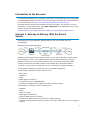
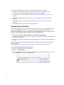
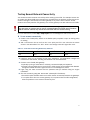
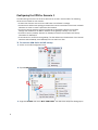
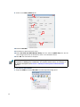
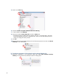
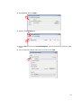
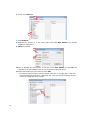
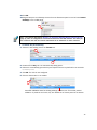
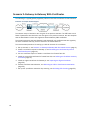
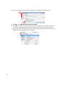
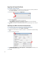
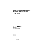
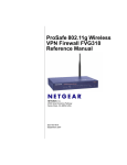
STONEGATE IPSEC VPN 5.1
VPN CONSORTIUM INTEROPERABILITY PROFILE
V IR TUAL PRIVATE NETWORKS
C ON T ENT S
Introduction to the Scenarios ............................................. 3
Scenario 1: Gateway-to-Gateway With Pre-Shared Secrets ..... 3
Configuring the Interfaces ............................................. 4
Configuring Routing ...................................................... 5
Testing General Network Connectivity ............................. 7
Configuring the VPN for Scenario 1 ................................ 8
Activating the VPN in the Firewall Policy .......................... 16
Diagnostics .................................................................. 17
Scenario 2: Gateway-to-Gateway With Certificates ................ 18
Generating the Certificate Keys and a Certificate Request 19
Defining the Certificate Authority as Trusted ................... 21
Importing the Signed Certificate .................................... 22
Switching the VPN to Certificate Authentication .............. 22
Activating CRL Checking ................................................ 23
2
Introduction to the Scenarios
This document describes how to configure a StoneGate Firewall/VPN engine as a VPN gateway
in interoperability Scenarios 1 and 2. These scenarios were developed by the VPN Consortium.
For more information, visit http://www.vpnc.org/InteropProfiles/Interop-01.html.
Only steps directly related to the scenarios are covered in detail in this document. For more
instructions on other related tasks, select Help→Help Topics in the Management Client’s top
menu or see the PDF documentation at
www.stonesoft.com/en/support/technical_support_and_documents/manuals/current/.
Scenario 1: Gateway-to-Gateway With Pre-Shared
Secrets
The following is a typical gateway-to-gateway VPN that uses a pre-shared secret for
authentication.
Illustration 1 Example Network Diagram
Gateway A connects the internal LAN 10.5.6.0/24 to the Internet. Gateway A's LAN interface
has the address 10.5.6.1, and its WAN (Internet) interface has the address 14.15.16.17.
Gateway B connects the internal LAN 172.23.9.0/24 to the Internet. Gateway B's WAN
(Internet) interface has the address 22.23.24.25. Gateway B's LAN interface address,
172.23.9.1, can be used for testing IPsec but is not needed for configuring Gateway A.
In this example, Gateway A was selected to be a StoneGate VPN gateway.
The IKE Phase 1 parameters used in Scenario 1 are:
•
•
•
•
•
•
Main mode
TripleDES
SHA-1
MODP group 2 (1024 bits)
Pre-shared secret of "hr5xb84l6aa9r6"
SA lifetime of 28800 seconds (eight hours) with no kbytes rekeying
The IKE Phase 2 parameters used in Scenario 1 are:
•
•
•
•
•
•
•
TripleDES
SHA-1
ESP tunnel mode
MODP group 2 (1024 bits)
Perfect forward secrecy for rekeying
SA lifetime of 3600 seconds (one hour) with no kbytes rekeying
Selectors for all IP protocols, all ports, between 10.5.6.0/24 and 172.23.9.0/24, using IPv4
subnets
3
The recommended procedure for setting up a VPN for scenario 1 is as follows:
1. Configure the Firewall/VPN engine’s interfaces for the network environment, see
Configuring the Interfaces (page 4) and Configuring Routing (page 5).
2. Test the basic connectivity without a VPN, see Testing General Network Connectivity
(page 7).
3. Define the VPN settings for the scenario 1, see Configuring the VPN for Scenario 1
(page 8).
4. Activate the VPN in the firewall’s policy, see Activating the VPN in the Firewall Policy
(page 16).
5. Verify that connections can use the VPN as expected.
Configuring the Interfaces
The interface configuration below assumes a single firewall is used in this configuration, but the
clustered configuration is similar. In a firewall cluster, the LAN and WAN IP addresses are
defined as CVI interfaces. For general connectivity, add NDI addresses for each node and each
network. The NDI addresses are not included in the VPN configuration.
T To prepare the friewall/VPN engine for the interface configuration
1. Configure a Firewall element with one interface: the Control interface for Management
Server communications.
2. Install the Firewall, and establish initial contact between the firewall and the Management
Server.
Detailed instructions for the preparations above can be found in the Firewall/VPN Installation
Guide available at
www.stonesoft.com/en/support/technical_support_and_documents/manuals/current/.
T To define the interfaces for the scenario
1. Open the properties of the Firewall element.
2. Switch to the Interfaces tab.
3. Use the Add button below the interface table to add two new Physical Interfaces, one for
the LAN interface and one for the WAN interface.
3
4
4. Right-click the LAN interface and select New→IP Address. The IP Address Properties dialog
opens.
4
5. Enter the LAN IP address 10.5.6.1 and click OK (the rest of the details are filled in
automatically).
6. Right-click the WAN interface and select New→IP Address. The IP Address Properties
dialog opens.
7. Enter the WAN IP address 14.15.16.17 and click OK.
8. Click OK to close the Firewall Properties dialog. A notification is displayed.
9. Click Yes. The Routing view opens.
Configuring Routing
T To add a single-link default route for the firewall/VPN gateway
1. Right-click the WAN interface network (14.15.16.0/24) and select New→Router. The
Router Properties dialog opens.
5
2. Name the element.
3. Type in the IP address of the next-hop router to the internet (the router would use some
address within the network 14.15.16.0/24 in this example scenario).
4. Click OK.
5. Right-click the Router you added and select New→Any Network from the menu that opens.
6. The routing view should now look similar to this:
6
Testing General Network Connectivity
You should test basic network connectivity before setting up the VPN. The example Access rule
we create here allows ICMP echo requests from any address to any address so that ping can be
used for testing the connectivity from either gateway or any host in either network. To test
network connectivity between the gateways, the remote gateway must also allow the test traffic.
Caution – Do not install a rule such as depicted here (allowing pinging from any host to
any other host) on a device that is used as a firewall between an actual internal network
and the Internet. Instead, only include the exact hosts that are used for testing.
For more instructions, select Help→Help Topics from the Management Client’s top menu.
T To test network connectivity
1. Create a new firewall policy based on the Default policy template or open an exiting policy
for editing.
2. Add a new Access rule as the first rule in the policy and fill in the cells with the values
shown in the table below. The “ANY” value is set through each cell’s right-click menu.
Table 1.1 Access Rule to Allow Ping Between Any Addresses
Source
ANY
Destination
ANY
Service
ANY
Action
Allow
3. Install the policy on the firewall. During policy installation, all configuration changes are
transferred to the firewall, including the interface and route definitions.
4. Connect to the firewall/VPN gateway:
• Physically by using a serial cable or a directly connected display and keyboard.
• Remotely using an SSH client (such as PuTTY). SSH access can be enabled and disabled
through the Firewall element’s right-click menu in the Management Client.
5. Login using the root username and the password that you defined during the engine
installation.
6. Give the command “ping 22.23.24.25” (Gateway B’s IP address).
• Successful replies indicate that there is basic network connectivity between the gateways.
• If no replies arrive from the remote gateway, do not proceed with the VPN configuration;
solve the problems in the network connectivity first.
7
Configuring the VPN for Scenario 1
The VPN settings are stored in elements that can be reused in several VPNs. The following
elements are needed for this scenario:
• A VPN Profile element sets the correct IKE Phase 1 and Phase 2 settings.
• A VPN element defines the topology and determines which combination of the other reusable
elements are used to create a particular VPN instance.
• An Internal Security Gateway element for Gateway A (StoneGate) defines the end-point
settings and establishes the WAN IP address as the gateway’s identity in the VPN.
• An External Security Gateway element for Gateway B contains the end-point and identity
information for Gateway B.
• A Site element is created for each gateway. The Site defines the IP addresses of the internal
networks behind Gateway A and Gateway B for use within the VPN.
T To create the VPN Profile for IKE settings
1. Switch to the VPN Configuration view.
1
2. Expand Other Elements.
2
3
3. Right-click Profiles and select New→VPN Profile. The VPN Profile Properties dialog opens.
8
4. Give the element a Name.
4
5. Switch to the IKE (Phase 1) tab.
5
6
7
8
6. For Cipher Algoritms, deselect AES-256 and select 3DES.
7. For Diffie-Hellman Groups, deselect 5 (1536 bits) and select 2 (1024 bits).
8. Change SA Lifetime in Minutes to 480 (8 hours). Your settings should now be identical to
those in the illustration above.
• Note that the SA lifetime is set in minutes in StoneGate. Other products may use seconds
as the unit. Double-check this value if you need to convert between different units.
• A mismatch in lifetime values may cut off the VPN until both gateways agree that the
lifetime has elapsed.
Note – The 3DES setting corresponds to “TripleDES” and the Diffie-Hellman Groups setting
to the “MODP group” in the scenario description. See Scenario 1: Gateway-to-Gateway With
Pre-Shared Secrets (page 3).
9
9. Switch to the IPsec (Phase 2) tab.
9
10
11
12
10.Deselect AES-256.
11.Set lifetime to 60 minutes (one hour).
12.Select Use PFS with Diffie-Hellman Group and then select 2 (1024 bits) from the list.
Your settings should now be identical to those in the illustration above.
13.Click OK. The VPN Profile is complete.
Note – The Use PFS with Diffie-Hellman Group setting with the associated drop-down list
corresponds to “MODP group 2 (1024 bits)” and “Perfect forward secrecy for rekeying” in
the scenario description (see Scenario 1: Gateway-to-Gateway With Pre-Shared Secrets
(page 3)).
T To create a VPN element
1. Right-click VPNs and select New VPN. The VPN Properties dialog opens.
1
10
2. Name the element.
2
3
Note that address translation
rules are not applied to
tunneled traffic by default.
3. Select the VPN profile you just created.
4. Click OK. The VPN opens for editing.
T To define the properties of the internal security gateway (Gateway A)
1. In the Resources panel, select Gateways.
2. Right-click somewhere in the Resources panel and select New→Internal Security
Gateway. The Internal Security Gateway Properties dialog opens.
3. Name the element.
3
4
4. Select the Firewall element that this Gateway represents.
11
5. Switch to the Sites tab.
5
6
7
8
6. Deselect Include and Update Addresses Based on Routing.
7. In the left panel, click Networks.
8. Select the network net-10.5.6.0/24 and click the Add button.
• The address space is added under the default “New Site” in the right panel. “New Site”
will be automatically renamed to “Gateway A Site” when you save the Gateway element
unless you change the name yourself.
9. Click OK.
10.Drag and drop the new Gateway element from the Resources panel on the left onto Central
Gateways in the middle panel.
10
T To define the properties of the external security gateway (Gateway B)
1. Right-click somewhere in the Resources panel and select New→External Security
Gateway. The External Security Gateway Properties dialog opens.
1
12
2. Type Gateway B as the Name.
2
3. Switch to the End-Points tab.
3
4
4. Click the New icon and select External End-Point. The External End-Point properties dialog
opens.
5. Type in Gateway B’s WAN IP address 22.23.24.25 and click OK.
5
13
6. Switch to the Sites tab.
6
7
7. Click Networks.
8. Right-click an element or in the empty space and select New Network. The Network
Properties dialog opens.
9. Name the element.
9
10
10.Type in Gateway B’s LAN network 172.23.9.0 as the IPv4 Address and click OK. The
Netmask is set automatically based on the IP address to 255.255.255.0.
11.Select the Network you just created and click Add.
• The address space is added under the default “New Site” in the right panel. “New Site”
will be automatically renamed to “Gateway B Site” when you save the Gateway element
unless you change the name yourself.
11
14
12.Click OK.
13.Drag and drop the new Gateway element from the Resources panel on the left onto Central
Gateways in the middle panel.
13
Note – The scenario description (Scenario 1: Gateway-to-Gateway With Pre-Shared Secrets
(page 3)) refers to configuration of selectors between the two LAN networks. The Sites you
just created for the local and remote LAN define the IP addresses for those selectors.
T To define the pre-shared key
1. Switch the VPN editing view to the Tunnels tab.
1
2
2. Double-click the Key cell. The Preshared Key dialog opens.
3. Delete the automatically generated key and replace with the key defined for the scenario:
hr5xb84l6aa9r6
4. Click OK. The VPN is now configured.
5. Click the Save button in the toolbar.
5
Automatic validation looks for missing settings, conflicts, etc. This tunnel passed
validation. If problems are found, they are detailed in the Issues panel at the bottom.
15
Activating the VPN in the Firewall Policy
The final phase in the VPN configuration is to allow connections in and out of the VPN in the
firewall Access rules. If you need more instructions for creating the Access rule, select
Help→Help Topics from the Management Client’s top menu to open the Online Help.
T To add a VPN Access rule
1. Add two new rules and define the Source, Destination, and Service cells as follows:
Table 1.2
Source
Destination
Service
Network element for Gateway A
LAN (10.5.6.0/24).
Network element for Gateway B
LAN (172.23.9.0/24).
ANY
Network element for Gateway B
LAN (172.23.9.0/24).
Network element for Gateway A
LAN (10.5.6.0/24).
ANY
2. Click the Action cell in one of the rules and select Use IPsec VPN. The IPsec VPN Action
dialog opens.
3. Under Action, select Enforce.
3
4
4. Under VPN, select the VPN you just created.
5. Click OK and repeat for the other rule. The rules should then look similar to this:.
6
6. Save the policy and install it on the firewall. The VPN configuration is also transferred at this
time.
The VPN is established when there is traffic that matches the Access rule you created (any LAN
A to LAN B traffic in the example network). VPN traffic is inspected in the same way as all other
traffic and some protocols may require the correct Protocol Agent to pass stateful inspection.
16
Diagnostics
You can monitor the VPN in the Status/Statistics view. The VPN remains grey (Unknown) until
there is traffic to/from the VPN. An active VPN is shown with a green color. Non-fatal errors turn
the status yellow (warning), and fatal errors turn the status red (error). When traffic through the
VPN stops, the unused tunnels are torn down after a timeout and the status turns blue (idle)
and, after some time, back to grey.
Detailed information about the VPN negotiatiations and traffic is available in the Logs view. To
view more detailed logging information when troubleshooting a VPN, you can enable diagnostic
logging for IPsec.
T To enable VPN diagnostics
1. Right-click the Firewall element and select Options→Diagnostics. The Diagnostics dialog
opens.
2. Select Diagnostic.
3. Select IPsec.
4. Click OK to confirm your selection. The diagnostics you selected are applied immediately.
5. Check the Logs view for IPsec-related log entries.
6. Disable the diagnostics when you are done examining the detailed information to reduce
the number of generated logs.
Tip – The online help system contains VPN troubleshooting information and explanations of the most
common VPN-related log messages.
17
Scenario 2: Gateway-to-Gateway With Certificates
The following is a typical gateway-to-gateway VPN that uses PKIX certificates for authentication.
Illustration 2 Example Network Diagram
The network setup is identical to the one given in the previous scenario. The IKE Phase 1 and
Phase 2 parameters are identical to the ones given in the previous scenario, with the exception
that the identification is done with signatures authenticated by PKIX certificates.
The scenario assumes that both Gateway A and Gateway B use certificates that are signed by
the same certificate authority, which is referred to as Trusted Root CA.
The recommended procedure for setting up a VPN for scenario 2 is as follows:
1. Set up scenario 1, see Scenario 1: Gateway-to-Gateway With Pre-Shared Secrets (page 3).
2. Create a certificate request for Gateway A, see Generating the Certificate Keys and a
Certificate Request (page 19).
3. Use the certificate request to obtain a certificate from Trusted Root CA.
4. Install the trusted CA certificate for Trusted Root CA, see Defining the Certificate Authority
as Trusted (page 21).
5. Install the signed certificate for Gateway A, see Importing the Signed Certificate
(page 22).
6. Activate certificate authentication, see Switching the VPN to Certificate Authentication
(page 22).
7. Set up CRL (certificate revocation list) checking, see Activating CRL Checking (page 23).
18
Generating the Certificate Keys and a Certificate Request
When you generate a certificate request, the private key to use that certificate is automatically
created on the firewall/VPN engine. The certificate request is used to generate a certificate for
the engine.
T To create a certificate request
1. Switch to the VPN Configuration view.
1
2. Click Gateways.
2
3
3. Right-click Gateway A and select Tools→Generate Certificate. The Generate Certificate
dialog opens.
19
4. Fill in the certificate request details according to your organization’s requirements.
4
5
5. For Sign, select With External Certificate Authority.
6. Click OK. A private key is generated for the firewall engine and a certificate request is
created and added as an element under Gateway A when both operations are finished.
7. Right-click the request and select Export Certificate Request. Save the file and send the
request file to the Trusted Root CA for signing.
7
20
Defining the Certificate Authority as Trusted
The firewall/VPN engine accepts (for itself and for other gateways) certificates signed by those
external certificate authorities that you define as trusted.
T To define a new certificate authority in the system
1. In the VPN Configuration view, expand Other Elements→Certificates.
2. Right-click VPN Certificate Authorities and select New VPN Certificate Authority. The
VPN Certificate Authority Properties dialog opens.
2
3. Type a Name for the element. This name is only for your reference.
4. Switch to the Certificate tab and do one of the following:
• Click the Import button and import a certificate file.
• Copy-paste the information into the field on the tab (including the “Begin Certificate”
header and “End Certificate” footer).
4
5. Click OK. If you see an invalid certificate error, the certificate you imported may be in an
unsupported format. Try converting the certificate to an X.509 certificate in PEM format
(Base64 encoding) using OpenSSL or the certificate tools included in Windows.
21
Importing the Signed Certificate
T To import a signed certificate
1. In the VPN Configuration view, right-click the certificate request you previously created and
select Import Certificate. The Import Certificate dialog opens.
2. Select the Trusted Root CA from the Signed by list.
2
3
3. Do one of the following:
• Click the Browse button and import a certificate file.
• Select As Text and copy-paste the information into the field on the tab (including the
“Begin Certificate” header and “End Certificate” footer).
4. Click OK. The certificate is automatically transferred to the firewall engine and is ready for
use.
Switching the VPN to Certificate Authentication
T To switch the VPN from pre-shared key to certificate authentication
1. In the VPN Configuration view, expand Profiles→VPN Profiles.
2. Double-click the VPN Profile you created for Scenario 1. The VPN Profile’s Properties dialog
opens.
3. Switch to the IKE (Phase 1) tab.
3
4
4. In Authentication Method, select RSA Signatures or DSA Signatures depending on the
type of the certificate you created.
5. Click OK.
22
6. Refresh the firewall’s policy to activate the switch from pre-shared keys to certificates in
VPN authentication. The same configuration change must be done also on Gateway B
before the VPN can work.
Activating CRL Checking
T To activate CRL checking
1. In the VPN Configuration view, expand Other Elements→Certificates→VPN Certificate
Authorities.
2. Double-click the Trusted Root CA you added. The certificate authority’s Properties dialog
opens.
3. Switch to the CRL List tab.
3
4
4. Select the CRL Validation option. This activates CRL checking from CRL servers listed in
the certificate authority’s root certificate.
5. (Optional) Define additional CRL(s) using the controls below. Ensure that the firewall engine
can reach these servers. If these servers cannot be reached when checking a certificate’s
validity, the certificate is considered invalid.
6. Click OK.
7. Refresh the firewall’s policy to activate the change.
23
StoneGate Guides
Administrator’s Guides - step-by-step instructions for configuring and managing the system.
Installation Guides - step-by-step instructions for installing and upgrading the system.
Reference Guides - system and feature descriptions with overviews to configuration tasks.
User's Guides - step-by-step instructions for end-users.
For more documentation, visit
www.stonesoft.com/support/
Stonesoft Corporation
Itälahdenkatu 22 A
FI-00210 Helsinki
Finland
Tel. +358 9 476 711
Fax +358 9 4767 1234
Stonesoft Inc.
1050 Crown Pointe Parkway
Suite 900
Atlanta, GA 30338
USA
Tel. +1 770 668 1125
Fax +1 770 668 1131
Copyright 2010 Stonesoft Corporation. All rights reserved. All specifications are subject to change.