1
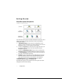
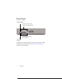
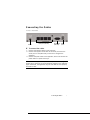
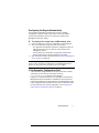
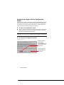
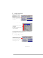
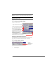
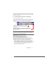
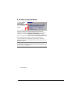
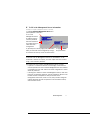
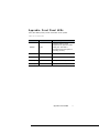
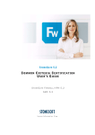
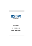
Appliance Installation Guide StoneGate FW-300 Legal Information End-User License Agreement The use of the products described in these materials is subject to the then current end-user license agreement, which can be found at the Stonesoft website: www.stonesoft.com/en/support/eula.html General Terms and Conditions of Support and Maintenance Services The support and maintenance services for the products described in these materials are provided pursuant to the general terms for support and maintenance services and the related service description, which can be found at the Stonesoft website: www.stonesoft.com/en/support/view_support_offering/terms/index.html Replacement Service The instructions for replacement service can be found at the Stonesoft website: www.stonesoft.com/en/support/view_support_offering/return_material_authorization/ index.html Hardware Warranty The appliances described in these materials have a limited hardware warranty. The terms of the hardware warranty can be found at the Stonesoft website: www.stonesoft.com/en/support/view_support_offering/warranty_service/index.html Trademarks and Patents The products described in these materials are protected by one or more of the following European and US patents: European Patent Nos. 1065844, 1259028, 1271283, 1289183, 1289202, 1313290, 1326393, 1379046, 1330095, 131711, 1317937 and 1443729 and US Patent Nos. 6,650,621; 6 856 621; 6,885,633; 6,912,200; 6,996,573; 7,099,284; 7,127,739; 7,130,266; 7,130,305; 7,146,421; 7,162,737, 7,234,166, 7,260,843, 7,280,540 and 7,302,480 and may be protected by other EU, US, or other patents, or pending applications. Stonesoft, the Stonesoft logo and StoneGate, are all trademarks or registered trademarks of Stonesoft Corporation. All other trademarks or registered trademarks are property of their respective owners. Disclaimer Although every precaution has been taken to prepare these materials, THESE MATERIALS ARE PROVIDED "AS-IS" and Stonesoft makes no warranty to the correctness of information and assumes no responsibility for errors, omissions, or resulting damages from the use of the information contained herein. All IP addresses in these materials were chosen at random and are used for illustrative purposes only. Copyright © 2008 Stonesoft Corporation. All rights reserved. All specifications are subject to change. Revision: SGAIG_FW-300_20080415 2 Introduction Thank you for choosing Stonesoft’s StoneGate appliance. This guide provides instructions for the initial hardware installation and the maintenance of the FW-300 appliances. The use of the appliance is subject to the acceptance of the End User License Agreement, which can be found at the Stonesoft website. Note – The purpose of this appliance installation guide is to help you get started with your StoneGate appliance. See Product Documentation, on page 5 for information on other available documentation. You must have a working Management Center on a separate server to bring the appliance(s) operational. The system architecture is explained on the next page. The installation of the Management Center and the configuration of your firewalls are explained in the StoneGate Firewall/ VPN Installation Guide. C on t ent s Getting Started ............................ 4 Safety Precautions ....................... 6 Front Panel .................................. 8 Connecting the Cables ................. 9 Initial Configuration ...................... 10 Maintenance Operations............... 19 Appendix: Front Panel LEDs .......... 21 Caution – Never open the covers of the appliance! There are no user serviceable parts inside. Opening the covers may lead to serious injury and will void the warranty. Read the Safety Precautions, on page 6 before you conduct any installation or maintenance operations on the appliance. Introduction 3 Getting Started StoneGate System Components Illustration 1 StoneGate Components The illustration above shows all available StoneGate components. Out of these, you need the following components to have an operational Firewall/VPN system: 1. A Management Server, which stores the configuration of the system. In most environments, it is best to have just one common Management Server for all firewall and IPS engines. 2. At least one Log Server to handle and store logs and alerts (can be installed simultaneously on the same machine with the Management Server). 3. At least one Management Client that you use to connect to the Management Server to change settings and monitor the system. 4. The Firewall Engines that handle the actual traffic processing (in this case, the StoneGate appliance). 5. Licenses for each component except the Management Client(s). Generate appliance licenses at the Stonesoft website with the POS (proof-of-serial-number) code attached to the appliance. The Monitoring Server and the Monitoring Client are optional components that are available on separate order. StoneGate IPS engines can be added to the same system for unified management and incident handling. 4 Getting Started Installation Procedure The appliance installation involves the following mandatory steps: 1. Configure and license the Firewall element in the Management Center (see the separate StoneGate Firewall/VPN Installation Guide or the online help of the Management Client). 2. Save the initial configuration to receive a one-time password for establishing trust between the appliance and the Management Server (see the separate StoneGate Firewall/VPN Installation Guide). 3. Connect the cables as instructed in this guide. 4. Perform the initial configuration and establish contact between the appliance and the Management Server (see Initial Configuration, on page 10). Product Documentation The following documentation covers the StoneGate Firewall/VPN products: • The StoneGate Firewall/VPN Installation Guide explains how to install the Management Center and configure your firewalls’ basic settings. • The online help system of the Management Client contains the stepby-step instructions for the daily configuration and management of your system. • The Administrator’s Guide contains the same information as the online help system, but in PDF form. • The Reference Guide contains background and reference information that helps you to plan and understand your system. Finding the Documentation Press F1 while in any Management Client window to view the online help. All PDF guides are available: • On the Management Center CD-ROM (in the Documentation folder) • At the Stonesoft Website at http://www.stonesoft.com/en/support/ technical_support_and_documents/manuals/. Install the free Adobe Reader program to view the PDF documents (available at www.adobe.com/reader/). If your order includes the Media Kit, the Installation Guide and Reference Guide are delivered to you as printed books. Getting Started 5 Safety Precautions The following safety information and procedures must be followed whenever working with the StoneGate Appliance. However, please be advised that StoneGate Appliances are not end-user serviceable, and you must never open the appliance covers for any reason. Doing so may lead to serious injury and will void any hardware warranty that may be associated with your appliance. Electrical Safety Precautions Basic electrical safety precautions should be followed to protect yourself from harm and the appliance from damage: • Be aware of the locations of the power on/off switch as well as the room's emergency power-off switch, disconnection switch, or electrical outlet. If an electrical accident occurs, you can then quickly cut power to the system. • Do not work alone when working with high voltage components. • Use only one hand when working with powered-on electrical equipment. This is to avoid making a complete circuit, which will cause electrical shock. Use extreme caution when using metal tools, which can easily damage any electrical components or circuit boards they come into contact with. • Do not use mats designed to decrease electrostatic discharge as protection from electrical shock. Instead, use rubber mats that have been specifically designed as electrical insulators. • The power supply cord must include a grounding plug and must be plugged into a grounded electrical outlet. Caution – Never open the appliance covers! There are no user serviceable parts inside. Opening the covers may lead to serious injury and will void the warranty. General Safety Precautions Follow these rules to ensure general safety: • Keep the area around the appliance clean and free of clutter. • We recommend using a regulating uninterruptible power supply (UPS) to protect the appliance from power surges, voltage spikes and to keep your system operating in case of a power failure. 6 Safety Precautions ESD Precautions Electrostatic discharge (ESD) is generated by two objects with different electrical charges coming into contact with each other. An electrical discharge is created to neutralize this difference, which can damage electronic components and printed circuit boards. Use a grounded wrist strap designed to prevent static discharge. Note – Use a UPS (Uninterruptible Power Supply) in critical environments with your StoneGate appliance. If after a brief power outage your StoneGate appliance only partially starts up (for example, the power light is on, but the NIC LEDs are off and the appliance does not connect) turn the appliance off for five seconds and then back on. Operating Precautions Care must be taken to assure that the appliance cover is in place when the appliance is operating to ensure proper cooling. If this rule is not strictly followed, the warranty may become void. Operating and Storage Temperatures The allowed operating temperature of the appliance is +10...+35ºC. The allowed storage temperature is 0...+70ºC. Do not operate or store the appliance in temperatures outside these limits. Lithium Battery Precautions Caution – Do not change the battery; the battery must be replaced by authorized service personnel only. Danger of explosion if battery is incorrectly replaced. Replacement battery must be same or equivalent type recommended by the manufacturer. Used batteries must be discarded according to the manufacturer’s instructions. Shortcircuiting the battery may heat the battery and cause severe injuries. Safety Precautions 7 Front Panel Illustration 2 Front Panel Power indicator Network activity and link indicator for each interface Link speed indicator for each interface Disk activity indicator The LEDs in the front panel provide you with critical information related to different parts of the system. See Appendix: Front Panel LEDs, on page 21 for more information. 8 Front Panel Connecting the Cables Illustration 3 Back Panel Power LAN ports (RJ-45) Serial port USB (RS-232) ports T To connect the cables 1. Connect the network cables to the LAN ports. 2. Connect the supplied serial cable to the serial port and to the serial port of a computer that you will use to configure the appliance. 3. Connect the power cable to the appliance, but do not connect the power cable to a power source yet. Note – When the appliance is powered and you need to unplug it, always wait at least five (5) seconds before plugging in the appliance again. Otherwise, the appliance may not have time to clear properly and fails to start. Connecting the Cables 9 Initial Configuration To start using the appliance, you must activate the network interfaces and establish a secure connection to the Management Server as outlined in the sections below. To successfully complete this configuration, the following prerequisites must be met: • The Firewall element must be defined in the Management Center. • You must have created a one-time password for this engine. See the StoneGate Firewall/VPN Installation Guide for details. • If you use the configuration wizard to configure the engine, you must have created a one-time password for this engine. • If you want to configure the engine automatically with a USB stick or to import some of the initial configuration information in the configuration wizard, you must have a saved initial configuration on a USB stick. See the StoneGate Firewall/VPN Installation Guide for details. Note – The appliance must contact the Management Server before it can be operational. Before starting the appliance, make sure you have a physical connection to the appliance using a monitor and keyboard or a serial cable (see Connecting the Cables, on page 9). • When using a serial line connection, use the terminal settings 9600bps, 8 databits, 1 stopbit, no parity. There are two ways to configure the engine software. • You can configure the engine automatically with a USB stick (see Configuring the Engine Automatically below). • If the automatic configuration is not possible or desired, you can use the engine configuration wizard (see Configuring the Engine with the Configuration Wizard, on page 12). 10 Initial Configuration Configuring the Engine Automatically The automatic configuration requires that you have a suitable configuration saved on a USB memory stick. See the StoneGate Firewall/VPN Installation Guide or the online help system of the Management Client for details. T To configure the engine from a USB memory stick 1. Insert the USB stick in one of the USB ports on the appliance. 2. Turn on the appliance using the power on/off button. • The appliance automatically imports the configuration from the USB stick and then tries to make the initial contact to the Management Server. • If the connection is successful, the appliance automatically reboots itself and the engine configuration is finished. 3. After successful contact, proceed to After Successful Management Server Contact, on page 18. Note – If you configure the engine automatically with a USB stick, you must set the command line password in the Management Client before you can access the command line on the engine. If the Automatic Configuration Fails • If the automatic configuration fails, and you do not have a display connected, you can check for the reason in the log (sg_autoconfig.log) written on the USB stick. • If you see a “connection refused” error message, ensure that the Management Server IP address is reachable from the engine and check the IP addresses you have defined in the Management Client. • If the configuration with the USB stick still does not succeed, follow the instructions for the manual configuration, see Configuring the Engine with the Configuration Wizard, on page 12. Initial Configuration 11 Configuring the Engine with the Configuration Wizard You can use the engine configuration wizard with all Management Center and firewall engine versions. If you have saved the initial configuration on a USB stick or a floppy disk, you can import it in the configuration wizard to reduce the need for typing in information. T To start the configuration wizard Turn on the appliance using the power on/off button. The engine bootup process is shown in the console and, after some time, the engine configuration wizard starts. Note – You can (re)start the engine configuration wizard at any time using the sg-reconfigure command on the engine command line. T To select the configuration method Illustration 4 Welcome To import a saved configuration, highlight Import using the arrow keys and press ENTER. To skip the import, highlight Next and press ENTER. 12 Initial Configuration T To set the keyboard layout Illustration 5 Configure OS Settings Highlight the entry field for Keyboard Layout using the arrow keys and press ENTER. The Select Keyboard Layout dialog opens. Illustration 6 Select Keyboard Layout Highlight the correct layout and press ENTER. Tip: Type in the first letter to move forward more quickly. If the desired keyboard layout is not available, use the best-matching available layout, or select US_English. T To set the engine’s timezone Illustration 7 Configure OS Settings 1. Highlight the entry field for Local Timezone using the arrow keys and press ENTER. 2. Select the correct timezone in the dialog that opens. Initial Configuration 13 Note – Timezone setting affects only the way the time is displayed on the engine command line. The actual operation always uses UTC time. Note – The appliance’s clock is automatically synchronized with the Management Server’s clock. T To set the rest of the OS settings Illustration 8 Configure OS Settings 1. Type in the name of the firewall. 2. Type in the password for the user root. This is the only account for engine command line access. 3. Highlight Enable SSH Daemon and press the spacebar on your keyboard to select the option and allow remote access to engine command line using SSH. 4. Highlight Next and press ENTER. The Configure Network Interfaces window is displayed. Configuring the Network Interfaces The configuration utility can automatically detect which network cards are in use. You can also add interfaces manually, if necessary. T To add the network interfaces Illustration 9 Configure Network Interfaces Highlight Autodetect and press ENTER. 14 Initial Configuration Check that the automatically detected drivers are correct and that all interfaces have been detected. To add interfaces manually, click Add and select a device driver. T To map the physical interfaces to interface IDs Illustration 10 Assigning Network Interfaces 1. Type in the IDs to define how physical interfaces are mapped to the Interface IDs you defined in the Firewall element. Ethernet ports are detailed in Illustration 3 in Connecting the Cables, on page 9. 2. Highlight the Media column and press ENTER to match the speed/duplex settings to those used in each network. 3. Highlight the Mgmt column and press the spacebar on your keyboard to select the correct interface for contact with the Management Server. Note – The Management interface must be the same that you configured as the Primary Control Interface for the corresponding Firewall element in the Management Center. Highlight Next and press ENTER to continue. Contacting the Management Server The Prepare for Management Contact window opens. If the initial configuration was imported, most of this information is filled in. This task has two parts. First, you activate an initial configuration: • The initial configuration contains the information that the engine needs to connect to the Management Server for the first time. • The initial configuration is replaced with a working configuration when you install a Firewall Policy from the Management Server on this engine using the Management Client. Initial Configuration 15 T To activate the initial configuration Illustration 11 Prepare for Management Contact - Upper Part 1. Highlight Switch Firewall Node to Initial Configuration and press spacebar to activate. 2. Fill in according to your environment. The information must match the settings you defined for the Firewall element (Primary Control IP Address). If the engine and the Management Server are on the same network, you can leave the Gateway to management field empty. The initial configuration contains a simple firewall policy that allows only administration-related connections and blocks everything else. In the second part of the configuration, you define the information needed for establishing a trust relationship between the engine and the Management Server. Note – If you do not have a one-time password for this firewall, see the StoneGate Firewall/VPN Installation Guide for instructions on how to save an initial configuration. 16 Initial Configuration T To fill in the Management Server information Illustration 12 Prepare for Management Contact - Lower Part 1. Highlight Contact Management Server and press spacebar to activate. 2. Fill in the Management Server IP address and the one-time password that was created for this engine when you saved the initial configuration. 3. (Optional) Fill in the Key fingerprint (also shown when you saved the initial configuration). Filling it in increases the security of the communications. 4. Highlight Finish and press ENTER Note – Once initial contact has been made, the engine receives a certificate from the Management Center for identification. If the certificate is deleted or expires, you must repeat the initial contact using a new one-time password. The engine now tries to make initial Management Server contact. • If you see a “connection refused” error message, ensure that the one-time password is correct and the Management Server IP address is reachable from the node. Save a new initial configuration if unsure about the password. • If the engine is unable to contact the Management Server, make sure there are no networking problems, that all information defined in the Firewall element corresponds to what you entered in the Configuration wizard and, if NAT is in use, that you have configured contact addresses for NAT as explained in the StoneGate Firewall/ VPN Installation Guide. Initial Configuration 17 After Successful Management Server Contact After you see a notification that Management Server contact has succeeded or the appliance has rebooted itself after automatic configuration with a USB stick, the firewall engine installation is complete and the firewall is ready to receive a policy. In a while, the firewall’s status changes in the Management Client from Unknown to No Policy Installed, and the connection state is Connected indicating that the Management Server can connect to the node. The next step is creating a security policy and installing it on the engine. See the StoneGate Firewall/VPN Installation Guide for basic instructions or the online help system of the Management Client for detailed instructions. Caution – When using the command prompt, use the reboot command to reboot and halt command to shut down the node. Do not use the init command. You can also reboot the node using the Management Client. 18 Initial Configuration Maintenance Operations Reverting to Previously Installed Software Version This procedure allows you to undo a software upgrade. The appliance has two working partitions. One is designated as active and the other as inactive. The inactive partition is used for upgrades and the status is switched between the partitions when the upgrade is ready to be activated. If the appliance does not start up with the new version, it automatically switches to the previous configuration at the next reboot. You can also switch back to the previously installed software version manually as instructed here whenever necessary. T To switch back to the previously active version 1. Connect the serial cable supplied with the appliance to the serial port on the appliance and to a computer. 2. On the computer, open a terminal with settings 9600bps, 8 databits, 1 stopbit, no parity. 3. (Re)start the appliance: • If the appliance is powered on and accessible, press Enter, log in and issue command reboot. • Otherwise, cycle the power off and on as appropriate. Note – When the appliance is powered and you need to unplug it, always wait at least five (5) seconds before plugging in the appliance again. Otherwise, the appliance may not have time to clear properly and fails to start. 4. Wait until a boot menu is shown. 5. Select Switch to previously installed software version. Note the indicated partition (A or B). The appliance switches partitions and boots up. 6. Refresh the policy on the firewall or firewall cluster to synchronize the policy and other configuration data between components. Note – If the certificate for system communications on the previously used partition is not valid anymore, see the Troubleshooting section in the Management Client’s online help for renewal instructions. If you want to undo this operation, repeat the steps exactly as above. Maintenance Operations 19 Resetting the Appliance to Factory Settings The primary way to reset the appliance’s settings is to run the configuration wizard (sg-reconfigure command line tool) and to select the Switch Firewall Node to Initial Configuration option. Note – Perform a factory reset only if you have a specific need to do so. Consult Stonesoft Support before performing this operation if you are unsure of whether this operation is necessary or not. T To reset to factory settings 1. Connect the serial cable supplied with the appliance to the serial port on the appliance and to a computer. 2. On the computer, open a terminal with settings 9600bps, 8 databits, 1 stopbit, no parity. 3. (Re)start the appliance: • If the appliance is powered on and accessible, press Enter, log in and issue command reboot. • Otherwise, cycle the power off and on as appropriate. Note – When the appliance is powered and you need to unplug it, always wait at least five (5) seconds before plugging in the appliance again. Otherwise, the appliance may not have time to clear properly and fails to start. 4. Wait until a boot menu is shown. 5. Select System Restore Options from the boot menu. 6. Type 1 and press Enter to clear the settings. A confirmation prompt is shown. 7. Type YES and press Enter to perform the reset. If you decide to cancel the operation, type NO and press Enter. Caution – Do not unplug the power from the appliance or interrupt the reset in any way. If the reset is interrupted, the appliance may become unusable until serviced. To use the appliance after a factory reset, you must configure it as explained in Initial Configuration, on page 10. 20 Maintenance Operations Appendix: Front Panel LEDs Front panel LEDs provide you with information on the system. TABLE 14.1 Front Panel LEDs LED Status Explanation POWER Green Indicates power is being supplied to the system's power supply unit. This LED is illuminated when the system is operating normally. STORAGE Red Blinks on hard drive activity. ACT/LINK Green Link ok, blinks on activity. 100 Mbps Unlit Link speed is 10 Mbps. 100 Mbps Green Link speed is 100 Mbps. Appendix: Front Panel LEDs 21 StoneGate Appliance Installation Guide This booklet covers the initial installation and configuration tasks specific to your StoneGate Appliance. For information on how to prepare the Management Center for a new engine installation, see the other available documentation. See inside for further details. All documentation and our technical knowledge base is available at www.stonesoft.com/support. Stonesoft Corporation Itälahdenkatu 22 A 00210 Helsinki Finland Stonesoft Inc. 1050 Crown Pointe Parkway Suite 900 Atlanta, GA 30338 USA Business ID: 0837548-0 Domicile: Helsinki Copyright 2008 Stonesoft Corporation. All rights Reserved. All specifications are subject to change.