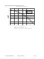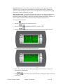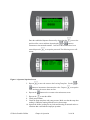
1
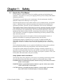
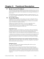
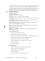
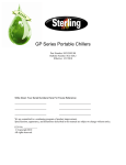
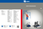
GP Series
Portable Chillers
Part Number: 882.93092.00
Bulletin Number: SC2-620
Effective: 5/1/2009
Write Down Your Serial Numbers Here For Future Reference:
_________________________
_________________________
_________________________
_________________________
_________________________
_________________________
We are committed to a continuing program of product improvement.
Specifications, appearance, and dimensions described in this manual are subject to change without notice.
ECN No. ____________
© Copyright 2009
All rights reserved.
Shipping Information
Unpacking and Inspection
You should inspect your equipment for possible shipping damage. Thoroughly check the
equipment for any damage that might have occurred in transit, such as broken or loose wiring
and components, loose hardware and mounting screws, etc.
In the Event of Shipping Damage
According to the contract terms and conditions of the Carrier, the responsibility of the
Shipper ends at the time and place of shipment.
Notify the transportation company’s local agent if you discover damage
Hold the damaged goods and packing material for the examining agent’s inspection. Do not
return any goods before the transportation company’s inspection and authorization.
File a claim with the transportation company. Substantiate the claim by referring to the
agent’s report. A certified copy of our invoice is available upon request. The original Bill of
Lading is attached to our original invoice. If the shipment was prepaid, write us for a
receipted transportation bill.
Advise customer service regarding your wish for assistance and to obtain an RMA (return
material authorization) number.
If the Shipment is Not Complete
Check the packing list as back-ordered items are noted on the packing list. In addition to the
equipment itself, you should have:
Bill of lading
Packing list
Operating and Installation packet
Electrical schematic and panel layout drawings
Component instruction manuals (if applicable)
Re-inspect the container and packing material to see if you missed any smaller items during
unpacking.
If the Shipment is Not Correct
If the shipment is not what you ordered, contact the parts and service department
immediately at (262) 641-8610. Have the order number and item number available.
Hold the items until you receive shipping instructions.
Returns
Do not return any damaged or incorrect items until you receive shipping instructions from the
shipping department.
GP Series Portable Chillers
ii
Table of Contents
CHAPTER 1: SAFETY................................................................ 5
1-1
1-2
1-3
How to Use This Manual ............................................................................................. 5
Safety Symbols Used in this Manual .....................................................................5
Warnings and Precautions .......................................................................................... 6
Responsibility .............................................................................................................. 6
CHAPTER 2: FUNCTIONAL DESCRIPTION ............................. 7
2-1
2-2
2-3
2-4
2-5
Models Covered in This Manual.................................................................................. 7
General Description..................................................................................................... 7
Chilled Water Circuit..............................................................................................7
Refrigeration Circuit...............................................................................................7
Standard Features....................................................................................................... 8
Mechanical Features .............................................................................................8
Electrical Features.................................................................................................8
Refrigeration Features...........................................................................................9
Controller Features................................................................................................9
Other Features ......................................................................................................9
Safety Devices and Interlocks ..................................................................................... 9
Crankcase Heater .................................................................................................9
High Pressure Cutout ..........................................................................................10
Low Pressure Cutout (no switch but done through the transducer) ....................10
Flow Switch .........................................................................................................10
Remote Start/Stop Interlock ................................................................................10
Optional Features...................................................................................................... 10
CHAPTER 3: INSTALLATION.................................................. 13
3-1
3-2
3-3
3-4
3-5
3-6
3-7
Uncrating ................................................................................................................... 13
Electrical Connections............................................................................................... 13
Process Water Connections ....................................................................................... 14
Bypass Valve Considerations.................................................................................... 14
Galvanic Corrosion Considerations........................................................................... 14
Water Treatment Considerations .............................................................................. 14
Condenser Considerations........................................................................................ 15
Water-Cooled Chiller Condensers.......................................................................15
Air-Cooled Chiller Condensers ............................................................................15
3-8
Checking Motor Direction .......................................................................................... 16
Three-Phase Compressors .................................................................................16
Water Pumps.......................................................................................................16
Condenser Fan....................................................................................................16
3-9
Water Reservoir ........................................................................................................ 17
3-10 Automatic Water Make-Up Option............................................................................. 19
3-11 Initial Start-Up............................................................................................................ 19
3-12 Finishing Setup: Setting Up Passwords .................................................................... 19
CHAPTER 4: OPERATION....................................................... 22
GP Series Portable Chillers
iii
4-1
4-2
4-3
4-4
4-5
4-6
4-7
Panel Buttons, Indicator Lights, and Switches .......................................................... 22
Microprocessor Controller ...................................................................................22
Initial Start-up ............................................................................................................ 23
Status Screens .......................................................................................................... 25
Access Levels ........................................................................................................... 26
Controller Setpoints................................................................................................... 28
Alarms ....................................................................................................................... 30
Optional Communications ......................................................................................... 30
CHAPTER 5: MAINTENANCE ................................................. 32
5-1
5-2
5-3
5-4
5-5
5-6
Lubrication................................................................................................................. 32
Filter Cleaning ........................................................................................................... 32
Maintaining the Condenser ....................................................................................... 32
Air- and Remote Air-Cooled Chillers ...................................................................32
Water-Cooled Chillers .........................................................................................32
Maintaining the Evaporator ....................................................................................... 33
Evaporator Process Piping Y-Strainer....................................................................... 33
Preventative Maintenance Service............................................................................ 33
CHAPTER 6: TROUBLESHOOTING ....................................... 34
CHAPTER 7: APPENDIX.......................................................... 36
7-1
7-2
7-3
7-4
7-5
Returned Material Policy ........................................................................................... 36
Credit Returns .....................................................................................................36
Technical Assistance................................................................................................. 37
Parts Department ................................................................................................37
Service Department.............................................................................................37
Sales Department................................................................................................37
Contract Department ...........................................................................................37
Specifications ............................................................................................................ 38
Air-Cooled Portable Chillers ................................................................................38
Water-Cooled Portable Chillers ...........................................................................40
Pump Curves, Flow, and Pressure Considerations................................................... 42
60 Hertz Pump Curves ........................................................................................42
Electrical Schematic .................................................................................................. 44
GP Series Portable Chillers
iv
Chapter 1:
1-1
Safety
How to Use This Manual
Use this manual as a guide and reference for installing, operating, and maintaining your
equipment. The purpose is to assist you in applying efficient, proven techniques that enhance
equipment productivity.
This manual covers only light corrective maintenance. No other maintenance should be
undertaken without first contacting a service engineer.
The Functional Description section outlines models covered, standard features, and optional
features. Additional sections within the manual provide instructions for installation, preoperational procedures, operation, preventive maintenance, and corrective maintenance.
The Installation chapter includes required data for receiving, unpacking, inspecting, and setup
of the equipment. We can also provide the assistance of a factory-trained technician to help
train your operator(s) for a nominal charge. This section includes instructions, checks, and
adjustments that should be followed before commencing with operation of the equipment.
These instructions are intended to supplement standard shop procedures performed at shift,
daily, and weekly intervals.
The Operation chapter includes a description of electrical and mechanical controls, in
addition to information for operating the equipment safely and efficiently.
The Maintenance chapter is intended to serve as a source of detailed assembly and
disassembly instructions for those areas of the equipment requiring service. Preventive
maintenance sections are included to ensure that your equipment provides excellent, long
service.
The Troubleshooting chapter serves as a guide for identification of most common problems.
Potential problems are listed, along with possible causes and related solutions.
The Appendix contains technical specifications, drawings, schematics, and parts lists. A
spare parts list with part numbers specific to your machine is provided with your shipping
paperwork package. Refer to this section for a listing of spare parts for purchase. Have your
serial number and model number ready when ordering.
Safety Symbols Used in this Manual
The following safety alert symbols are used to alert you to potential personal injury hazards.
Obey all safety messages that follow these symbols to avoid possible injury or death.
DANGER indicates an imminently hazardous situation which, if not avoided, will result in
death or serious injury.
WARNING indicates a potentially hazardous situation or practice which, if not avoided,
could result in death or serious injury.
CAUTION indicates a potentially hazardous situation or practice which, if not avoided,
may result in minor or moderate injury or in property damage.
GP Series Portable Chillers
Chapter 1: Safety
5 of 44
1-2
Warnings and Precautions
Our equipment is designed to provide safe and reliable operation when installed and operated
within design specifications, following national and local safety codes.
To avoid possible personal injury or equipment damage when installing, operating, or
maintaining this equipment, use good judgment and follow these safe practices:
9 Follow all SAFETY CODES.
9 Wear SAFETY GLASSES and WORK GLOVES.
9 Disconnect and/or lock out power before servicing or maintaining the equipment.
9 Use care when LOADING, UNLOADING, RIGGING, or MOVING this
equipment.
9 Operate this equipment within design specifications.
9 OPEN, TAG, and LOCK ALL DISCONNECTS before working on equipment.
You should remove the fuses and carry them with you.
9 Make sure the equipment and components are properly GROUNDED before you
switch on power.
9 When welding or brazing in or around this equipment, make sure
VENTILATION is ADEQUATE. PROTECT adjacent materials from flame or
sparks by shielding with sheet metal. An approved FIRE EXTINGUISHER
should be close at hand and ready for use if needed.
9 Refrigeration systems can develop refrigerant pressures in excess of 500 psi
(3,447.5 kPa/ 34.47 bars). DO NOT CUT INTO THE REFRIGERATION
SYSTEM. This must be performed by a qualified service technician only.
9 Do not restore power until you remove all tools, test equipment, etc., and the
equipment and related components are fully reassembled.
9 Only PROPERLY TRAINED personnel familiar with the information in this
manual should work on this equipment.
We have long recognized the importance of safety and have designed and manufactured our
equipment with operator safety as a prime consideration. We expect you, as a user, to abide
by the foregoing recommendations in order to make operator safety a reality.
1-3
Responsibility
These machines are constructed for maximum operator safety when used under standard
operating conditions and when recommended instructions are followed in the maintenance
and operation of the machine.
All personnel engaged in the use of the machine should become familiar with its operation as
described in this manual.
Proper operation of the machine promotes safety for the operator and all workers in its
vicinity.
Each individual must take responsibility for observing the prescribed safety rules as outlined.
All warning and danger signs must be observed and obeyed. All actual or potential danger
areas must be reported to your immediate supervisor.
GP Series Portable Chillers
Chapter 1: Safety
6 of 44
Chapter 2:
2-1
Functional Description
Models Covered in This Manual
This manual provides operation, installation, and maintenance instructions for air-, water-and
remote air-cooled portable chillers. Model numbers are listed on the serial tag. Make sure you
know the model and serial number of your equipment before contacting the manufacturer for
parts or service.
Our portable chiller models are designated by approximate compressor horsepower (5,7 1/2,
10, 13 and 15 etc) and the cooling method used: -A for air-cooled, -W for water-cooled, and –
R for remote-air cooled.
2-2
General Description
Our portable chillers are reliable, accurate, and easy to use process cooling units. They are
available in air-, water-, and remote air-cooled designs in a range of sizes from 5 to 15 tons.
All are self-contained, fully portable and shipped ready to use. (Remote air-cooled chillers
require field installation by qualified technicians.)
Standard range of operation is 20ºF to 80ºF (-7ºC to 30ºC) for applications using a
water/glycol mix and 45ºF to 80ºF (7º to 30ºC) for water only applications.
A factory installed crankcase pressure regulating valve option is available for processes
requiring a leaving water temperature over 80ºF (30ºC).
Chilled Water Circuit
Cooling water “To Process” and “From Process” connections are made at the female NPT
couplings provided outside the unit. Warm coolant (water and glycol mixture) returns from
the process and goes into the reservoir tank. The coolant is then pumped through the
evaporator where it is cooled. The coolant flows to the process and returns to repeat the cycle.
A (manual) pressure actuated process water bypass valve located between the supply line and
reservoir tank (single pump models only) allows minimal flow through the unit during the
intermittent fluctuating flow conditions. It is not intended to provide continuous full bypass
flow.
This minimal flow allows the temperature sensor to signal the controller to shut down the
compressor because of the drop in process water temperature. Typically the flow switch shuts
down the chiller in this low flow condition. This valve allows enough flow for the chiller to
function when the flow is shut off to process.
Refrigeration Circuit
Air-, water-, and remote air-cooled refrigerant condensing differ only in the way the
compressed gas is condensed to a liquid.
Liquid refrigerant from the condenser heat exchanger flowing in the liquid line passes
through a shut-off valve into a filter/dryer that removes moisture and other contaminants. A
refrigerant sight glass is provided. The refrigerant then passes through the thermal expansion
valve, which allows the refrigerant to expand (boil off) and cool (remove the heat from) the
fluid inside of the evaporator. The refrigerant gas flows through the suction line back into the
compressor.
GP Series Portable Chillers
Chapter 2: Functional Description
7 of 44
The refrigerant is compressed in the compressor and flows through the discharge line as a gas
to the condenser. There it gives up its heat as it condenses to a liquid in the condenser.
An electronic hot gas bypass valve is used to control cooling capacity during intermittent or
partial load conditions. This feature contributes substantially to chiller longevity by
eliminating excessive cycling of the compressor and providing close temperature control.
2-3
Standard Features
Mechanical Features
Compressor. Hermetic scroll compressors.
Evaporator. Stainless steel copper brazed plate evaporators.
Air-Cooled Condenser. Aluminum fin/ tube with washable filters, package unit only (option
on remotes).
Water-Cooled Condenser. Tube-in-tube condensers. All come with electronic cooling
water regulating valves for cooling tower water or city water.
Remote Air-Cooled Condenser. Aluminum fin/tube with low ambient control down to –
20ºF (-29ºC) via a variable-speed primary fan.
Reservoir. 5 hp and 7.5 hp models use a 20 gallon polyethylene tank. 10 hp and 15 hp
models use a 40 gallon polyethylene tank.
Piping. Non-ferrous piping
Pump. TEFC motors (Optional 10 HP is ODP only)—horizontally mounted stamped
stainless steel construction.
Other Mechanical Features
• Low process water thermal flow switch
• NEMA-rated fan motor(s) on air-cooled models
• Galvanized structural steel frame, painted cabinetry, with 4” (locking) swivel casters
• Internal process water bypass valve for system protection only
• Fully insulated refrigeration and process water piping
• 20 mesh Y strainer on process water piping into the evaporator
• Tank level indication
• Pump pressure indication
Electrical Features
• Fully accessible NEMA 12-style electrical control enclosure
• Single-point power and ground connection
• Non-fused disconnect switch, lockable
• Branch circuit fusing
• 208-230/3/60, 460/3/60, 575/3/60 volt; 400/3/50 volt
GP Series Portable Chillers
Chapter 2: Functional Description
8 of 44
Refrigeration Features
• HFC-410a refrigerant
• Electronic hot gas bypass capacity control
• High refrigerant pressure cutout switches
• Suction and discharge pressure transducers.
• High pressure spring actuated relief valve
• Multiple refrigeration access ports
• Liquid line shut-off ball valves
• Filter-dryer
• Sight glass
• Externally equalized thermal expansion valve
• Liquid line solenoid
• Compressor crankcase heater
Controller Features
• Off-the-shelf microprocessor-based PID auto-tuning controller with To Process, From
Process and Set Point readout
• Time delay for proof of water flow/pressure (models w/pump only)
• Low refrigerant pressure time delay for low ambient start-up on remote air-cooled and
air-cooled chillers with the variable-speed fan option.
• 4 line x 20 character display with status, alarm, and service screens
Other Features
• One year labor warranty and one year compressor warranty
• Two year parts warranty
• Two year limited controller warranty
2-4
Safety Devices and Interlocks
Caution! Protect the system from freezing with glycol 20ºF below the leaving water
temperature set point. Condensation may form inside the pump tank and dilute
the mixture, therefore the freezing point should be verified periodically. See
Figure 6 on page 18 for the correct mixture.
Crankcase Heater
5 hp through 15 hp portable chillers have a crankcase heater. It is wired through the control
transformer that operates continuously whenever power is applied to the chiller.
Caution! Energize the crankcase heater for at least 24 hours before initial startup to
drive dissolved refrigerant from the compressor oil. Failure to do so will
damage the compressor.
GP Series Portable Chillers
Chapter 2: Functional Description
9 of 44
High Pressure Cutout
This electro-mechanical cutout device opens the compressor control circuit if the refrigeration
system compressor discharge pressure exceeds 575 psi..
Note:
The high-pressure cutout is a manual reset device typically mounted on the
compressor discharge line inside the mechanical cabinet. Call a refrigeration
service technician to analyze the problem and reset the control.
Low Pressure Cutout (no switch but done through the transducer)
This electro-mechanical cutout device opens the compressor control circuit if refrigeration
system compressor suction pressure drops below 15 psi. It automatically resets when
refrigerant suction pressure reaches 30 psi.
Note:
The low pressure cutout is an automatic reset device typically mounted on the
compressor suction line inside the mechanical cabinet. Call a refrigeration
service technician to analyze the problem and reset the control.
Flow Switch
The thermal dispersion flow switch cutout device, mounted in the process piping, shuts down
the chiller if it senses that the water/glycol flow rate through the evaporator has dropped
below an acceptable level. The flow switch opens the control circuit and shuts down the
pumps and the chiller.
Remote Start/Stop Interlock
An additional contact is provided to allow the remote starting or stopping of the chiller. To
use this feature, remove the jumper between terminals X1 and 1, and supply a switch or dry
contact interlock connected in series between these two terminals. Refer to the schematic
inside the control enclosure door.
2-5
Optional Features
Options marked with “*” indicate options that can be factory installed or retrofitted in the
field.
Automatic Water Make-Up*. Not available on chillers less reservoir tank. Includes an
electric water solenoid valve, a level sensing pressure switch mounted in the reservoir tank,
and the necessary internal piping to connect the chiller to a make-up water source. See
Appendix for typical piping diagrams.
Caution! Customer piping must provide backflow protection and venting of tank to
atmosphere to prevent over-pressurization of the reservoir tank (not needed for
open tank). See Error! Reference source not found. on page Error! Bookmark
not defined..
Process Water Sidestream Filter*. Not available on chillers less pump and reservoir tank.
Includes a 50 micron filter, flow meter, ball valve for throttling water flow, and the necessary
piping to provide constant filtering of the process water at about one gallon per minute (1
gpm/3.8lpm).
General Fault Indicator Audible/Visual Alarm*. Includes a 100 dB audible alarm horn/
visual alarm strobe and silence button with provisions for customer wiring indication
GP Series Portable Chillers
Chapter 2: Functional Description
10 of 44
interlock. The alarm signals anytime that a fault is recognized during the operation of the
chiller.
Communications Options. RS-485 serial Modbus communications.
High Pressure Fans. Provides for an additional 1.0”WC (250 Pa) of static pressure on fan
discharge. High-pressure fans are necessary and must be included in chiller installations
where exiting air exhausts through ductwork.
They can be retrofitted without sheet metal modification, but will require changing out fan
blades, and in some cases, fan motors and electrical components.
Variable Speed Fan. Reduces the speed of the fan based on entering air temperature and
system load, allowing the chiller to operate in ambient temperatures below 60ºF (15.5ºC).
This option will also reduce fan noise in ambient temperatures below 95ºF (35ºC).
Stainless Steel Reservoir. 5 hp to 15 hp models only. Manufactured from 304 stainless steel.
Mounting Features.
• Mounting rails with feet
Optional Operating Voltages. 208-230/3/60, 575/3/60, and 400/3/50 volt available
UL Labeled Electrical Subpanel. Provides for the subpanel to be listed with Underwriters
Laboratory, with UL-related benefits and features.
Optional Pumps. Pump options are available for greater pressure and flow rates. A
recirculation pump is required whenever process water flow is less than 1.2 gpm per ton or
greater than 4.8 gpm per ton. See Figure 1 on page 12 for optional pump amperages.
NEMA 4 Electrical Enclosure. Provides for NEMA 4-level electrical enclosure protection.
GP Series Portable Chillers
Chapter 2: Functional Description
11 of 44
Figure 1: Optional Pump Amperages
Voltage
Construction
HP
460/3/60
SS
1
1.7
1.5
2.3
2
4.0
3
4.2
5
8.2
10
12.0
GP Series Portable Chillers
Chapter 2: Functional Description
Full Load Amps
12 of 44
Chapter 3:
3-1
Installation
Uncrating
All models are are shipped mounted on a skid, enclosed in a plastic wrapper, and open-crated
on all four sides and top.
1. Pry the crating away from the skid.
2. Use a pry bar to remove the blocks securing the unit to the skid.
3. Lift unit from sides, inserting forklift under the base. The forks must be equidistant
from the centerline of the unit and the unit must be balanced on the forks. Lift slowly
and only high enough to clear the skid. Use a pry bar if necessary to carefully remove
the skid from the unit.
4. Lower slowly. The unit should land on its casters or rails and can then be moved into
position.
5. Retain the crating material for reshipping the chiller in case hidden shipping damage
is found.
3-2
Electrical Connections
Supply electricity of the voltage, phase, and cycle listed on the serial tag. Total running amps
are also found in the specification tables on pages in the Appendix.
Bring properly sized power leads and ground from a fused disconnect (installed by your
electrician) to the unit. Use dual-element fuses in the disconnect switch, sized according to
the National Electrical Code recommendations. Note the outline drawings for egress into the
cabinet. Make sure all electrical connections are tight.
Important!
Refer to your local electrical requirements for proper feeder conductor and
supply disconnecting sizing. For instance, in the United States refer to
National Electric Code (NEC) Article 430-24 through 430-26, Table
310.15(B)(2)(a)
GP Series Portable Chillers
Chapter 3: Installation
13 of 44
3-3
Process Water Connections
All of our portable chillers have two chilled water connections. The chilled water supply,
labeled “To Process” is the outlet for the chilled water leading to the process being cooled.
The chilled water return, labeled “From Process” is the inlet leading from the process back
into the chiller to be cooled and re-circulated.
All external chilled water connections should be run full size to the process. Flow and
pressure information is available in the Appendix. The largest possible openings and
passages should be provided for the flow of chilled water through platens, dies, molds, or
other pieces of equipment.
Note:
3-4
Be sure to reduce external pressure drop as much as possible by generously
sizing piping and tooling water passageways.
Bypass Valve Considerations
Our portable chillers have an internal manual bypass valve. If the flow is stopped to the
process while the chiller is running, the factory-set bypass valve allows a small amount of
water to flow through the chiller. This action allows the chiller to keep functioning while the
flow is stopped to process. The bypass valve is not intended to provide continuous full
bypass flow.
Caution! Do not attempt to adjust or otherwise tamper with the internal bypass. Your
warranty will be voided.
3-5
Galvanic Corrosion Considerations
The materials used in the water circuit piping of these chillers are non-ferrous and react
electro-chemically with ferrous metallic materials. Some water has dissolved minerals that
greatly accelerate the reaction between dissimilar metals.
PVC or non-ferrous piping is recommended to reduce galvanic action. If iron piping must be
used, use dielectric unions at the chiller.
3-6
Water Treatment Considerations
Water treatment is an integral part of the system. In some locations, water may cause large
deposits of scale, erosion, algae, and/or corrosion.
Note:
The use of poor quality water may result in inefficient operation, heat
exchanger damage, and pump seal damage. Consult a qualified water
treatment specialist to determine whether treatment is needed.
We offer a complete line of water treatment equipment. Contact your sales representative for
water testing and treatment options.
GP Series Portable Chillers
Chapter 3: Installation
14 of 44
3-7
Condenser Considerations
Water-Cooled Chiller Condensers
Water-cooled portable chillers can use city water or tower water as a cooling medium. Make
sure that all external piping and connections supplying and discharging water to and from the
condenser are full size.
You’ll make two connections to the water-cooled condenser:
Condenser Water In. The condenser water supply, labeled “Condenser Water In”, is located
at the rear of the chiller. It is the inlet for city or tower water.
Make sure that water is supplied at a maximum temperature of 85ºF (29ºC) and a minimum
pressure of 25 psi.
Caution! The electronic water-regulating valves pressure setpoint is set at the factory.
Only a qualified refrigeration technician should adjust the pressure setting
through the service section of the controller.
Normal HFC-410a refrigerant condensing pressure is 342 psi (2,360 kPa), with 85ºF (27ºC)
water at 25 psi entering condenser water pressure
Condenser Water Out. Condenser water return, labeled “Condenser Water Out”, is located
at the rear of the chiller. It is the outlet for water after it has passed through the condenser.
It is connected to the tower water return line or to a sewer or other approved discharge
receiver. A water-regulating valve is a standard feature in the condenser water out line.
Air-Cooled Chiller Condensers
Air-cooled chillers use the surrounding air to cool the condenser. Install the chiller in an area
where there is free passage of air for condensing and provisions for removal of heated air
from the area. Do not locate air-cooled chillers in locations where steam, hot air, or fume
exhausts can be drawn into the chiller.
Caution! Clean air-cooled condensers and filters frequently. Failure to do so results in
reduced capacity, increased operating costs, and possible failure of the
equipment. Cleaning instructions can be found in the Maintenance chapter of
this manual
Normal maximum refrigerant condensing pressure with 95ºF (35ºC) air entering the
condenser is 420 psi (2896 kPa).
Condensing Air Temperature. Our air-cooled portable chillers are designed to operate at a
minimum condenser entering air temperature of approximately 60ºF (15.5ºC). Operation of
the equipment at a lower condenser entering air temperature can cause the chiller to
malfunction. For entering air temperatures below 60ºF (15.5°C), an optional fan motor speed
control is available. We recommend maintaining a minimum 60ºF (15.5°C) ambient
temperature.
GP Series Portable Chillers
Chapter 3: Installation
15 of 44
3-8
Checking Motor Direction
All of our portable chillers have their motor rotations properly phased at the factory. If
compressors, pumps, or fans are running in reverse rotation, disconnect and lock out the
power source and reverse any two power leads into the chiller disconnect switch.
Caution! Do not switch leads at the motors, motor starters, or contactors.
Three-Phase Compressors
Scroll compressors are directionally-dependent and compress in one rotational direction.
Reversing rotation direction results in an elevated sound level and a substantially-reduced
current draw.
Water Pumps
Correct pump rotation is indicated by a positive pressure of 20 to 40 psi on the pump pressure
gauge. Pump rotation should be clockwise when viewed from the motor end. For chillers with
optional pumps, check the appropriate pump curve in the Appendix.
Caution! Do not run pump dry. Doing so will result in seal damage.
Condenser Fan
Air should be drawn through the condenser and discharged vertically from the chiller.
GP Series Portable Chillers
Chapter 3: Installation
16 of 44
3-9
Water Reservoir
All portable chillers shipped during the fall, winter, or spring, or those units that are shipped
from stock are flushed at the factory with a water/ethylene glycol solution to prevent piping
components prone to retaining water from freezing. During startup and when additional
solution is required, refer to the ethylene glycol and propylene glycol curves in Figure 6 on
page 20 Add a pre-mixed solution of industrial quality (not automotive) ethylene glycol or
propylene glycol and water to provide freeze protection to a temperature 20ºF (11ºC) below
the normal chiller operating temperature set point.
Glycol and/or water, with an inhibitor, should be used to protect the materials (copper, steel,
stainless steel, and bronze) in the system from corrosion. If you intend to use straight water,
we strongly advise a minimum leaving water temperature of 45ºF (7ºC) or contact the service
department.
The following glycol products are available:
Part Number
Description
A0541358
Ethylene glycol, 5 gallons (18.9 liters)
A0539637
Ethylene glycol, 55 gallons (208.2 liters)
A0542990
Propylene glycol, 5 gallons (18.9 liters)
A0542991
Propylene glycol, 55 gallons (208.2 liters)
Caution! Do not connect make-up water directly to the chilled water reservoir unless you
have an approved automatic water make-up system installed.
Caution! Do not pressurize tank. Supply and return connections must be trapped and
vented to allow vertical risers to drain into tank. Do not overfill system. Allow
enough free space in tank for vertical piping to drain.
If your application has chilled water or process piping above the reservoir fill and vent level,
trap and vent the supply and return lines to allow vertical piping to drain into tank.
Note:
In applications where the process or process piping is above the reservoir, take
steps to prevent over pressurization of the reservoir. This condition can occur
on system shutdown when the water in the system drains into the reservoir. To
prevent this, a vacuum breaker should be installed at the high point of the “To
Process” and “From Process” lines.
GP Series Portable Chillers
Chapter 3: Installation
17 of 44
Figure 2: Ethylene Glycol and Propylene Glycol Curves
Pe rce n t G lyc o l Cu rves fo r F ree ze P ro tec tion
40.0
30.0
Eth ylene G lycol
20.0
P rop ylene G lyc ol
10.0
0.0
-10.0
-20.0
-30.0
-40.0
-50.0
-60.0
0.0
10.0
20.0
30.0
40.0
50.0
60.0
% Gl ycol by Vol um e
Example: 45°F set point minus 20°F = 25°F.
From Figure 28, 25°F equates to 10% by volume of glycol required.
GP Series Portable Chillers
Chapter 3: Installation
18 of 44
3-10 Automatic Water Make-Up Option
The chiller may be connected to an automatic make-up system if the optional package (pipe
fittings, solenoid valve and 1/2” NPT city water make-up connection) is factory installed.
If the automatic make-up system is connected to a city water system, make provisions to
prevent backflow contamination. Install an approved backflow preventer in accordance with
local codes.
Caution! Adding straight city water into a glycol/water mixture dilutes the solution and
eventually leads to system freeze-up. Damage from freeze-up is not covered by
the warranty.
To prevent system freeze-up in automatic make-up applications, we recommend using either
a chemical feeder or make-up reservoir to replenish glycol. Contact the sales department for
more information about these configurations.
3-11 Initial Start-Up
• Check the shipping papers against the serial tag to be sure chiller size, type and voltage
is correct for the process that will be controlled. Portable chillers are built with a
voltage specific compressor and cannot be re-wired for an alternate voltage.
• Check the transformer primary voltage connections to be sure they are configured for
the electrical power you are using. The voltage at the main power connection must read
within plus or minus ten percent (±10%) of the voltage listed on the serial tag.
Electrical connections must conform to all applicable codes.
• Complete chilled water To Process and From Process connections.
• Be sure the reservoir tank and chilled water circuit piping are filled a water/glycol
mixture. The water/glycol mixture should provide for freeze protection to at least 20°F
(11ºC) below the leaving water temperature you want. Should the display show a tank
level less than 0 after the tank is filled, check the clear tube leading from the tank to the
tank level pressure switch for a blockage.
• The air-cooled condenser should have an adequate supply of 60º to 115ºF (16º to 46ºC)
air for proper operation.
• The tower or city water condenser cooling in and out connections should be completed
and an adequate supply of 85ºF (30ºC) tower or 70ºF (21ºC) city water, at 25 psi
pressure, for proper operation.
• Connect the main 3 phase incoming power to the unit making certain that line one (1)
L1 is connected to the A phase, line two (2) L2 is connected to the B phase, and line
three (3) L3 is connected to the C phase. Check for proper rotation direction of fan(s)
and pump(s).
The crankcase heater is automatically energized when the main power is applied. It
should be on for at least 24 hours before startup to force dissolved refrigerant from the
compressor oil.
3-12 Finishing Setup: Setting Up Passwords
You can establish passwords for two levels of security: operators and supervisors. The
controller comes from the factory with neither password set. This allows every user access to
all functions.
GP Series Portable Chillers
Chapter 3: Installation
19 of 44
Operator Password. If you define a password for operators, then a password will be
required to carry out any fuction (other than reviewing the status screens). Entering the
operator’s password will give the user access to the setpoints for leaving temperature, high
temperature warning, high temperature fault.
Supervisor Password. If you define a password for supervisors (or setup personnel) then
most settings can be changed only after entering the password. The password will be
required to display the extended setpoints for operating parameters and alarms. Section 4-6
shows a table of setpoints and the restrictions between Operator and Supervisor.
To set password protections:
1. Press the
button to access the menu screen.
2. Press the
or
to highlight SETPOINTS, and press
3. Press the
or
until the following screen appears for the Operator Password
.
or the following screen for the Supervisor Password
to accept the screen, and then press
4. Press
Password line is highlighted.
5. Press
or
0 and 9999.
GP Series Portable Chillers
until the Operator or Supervisor
to increment or decrement the number. The password can be between
Chapter 3: Installation
20 of 44
6. Press
to accept the Password and move to the next line.
7. For either Operator or Supervisor password the time that the password will allow the
controller to be active can be set by the Operator or Supervisor Password Time. With the
or
to increment or decrement the time. The
PW Time value highlighted, press
password time for either setup can be from 0 to 99 minutes.
GP Series Portable Chillers
Chapter 3: Installation
21 of 44
Chapter 4:
4-1
Operation
Panel Buttons, Indicator Lights, and Switches
Microprocessor Controller
The standard chillers use a microprocessor-based PID controller. The Carel PCO controller
along with the Carel PGD1 Interface is a modular, self-contained unit that can slide from its
mounting housing. It is factory set and adjusted; no field adjustment to the internal controls is
necessary. The standard operation range is 20ºF to 80ºF (-7ºC to 27ºC).
Figure 3 - Controller Display
Button
Button Description
Detailed description
Menu Button
Used to access the menus structure of the PGD interface
On/Off Button
Used to turn the entire chiller On or Off. The button is backlit and will
turn amber when the chiller is On.
Back Button
Used to back up from a menu and return to the main status screen
Up Arrow Button
Used to increment a data field or scroll up within a menu structure.
Enter Button
Used to accept a data field value or to select a menu item.
Down Arrow Button
Used to decrement a data field or scroll down within a menu structure.
GP Series Portable Chillers
Chapter 4: Operation
22 of 44
4-2
Initial Start-up
1. Verify the initial start-up checklist from Chapter 3, Section 3-11.
2. With the main supply power switch in the ON position, the screen will
display the version of the software for a period of 5 seconds, and then display
the main status screen.
Figure 4 - Main Status Screen
3. Set the Leaving Fluid temperature by depressing the
the menu.
button to display
Figure 5 - Menu Screen
or
button to highlight SETPOINTS and press
. If
4. Depress the
passwords were setup (See Section 3-12 for information on the controller
passwords) the password screen will appear.
GP Series Portable Chillers
Chapter 4: Operation
23 of 44
Enter the established Operator Password by depressing the
to move the
position of the cursor, and then depressing the
or
button to
increment or decrement the number. Once all of the numbers have been
entered depress the
appear.
to accept the password. The following screen will
Figure 6 - Operator Setpoints Screen
to move the cursor to the Leaving Temp line. Use the
5. Depress
button to increment or decrement the value. Depress
value and move the cursor down one line.
6. Depress the
or
to accept the
button twice to return to the main status screen.
7. Depress the
to start the chiller.
8. Check pump rotation
9. Check the pump amp draw and pump pressure. Make sure that the amp draw
reading is within the running load and service factor amps.
10. Operate the chiller, looking for any leaks and listening for unusual noises or
vibrations that could indicate improper operation.
GP Series Portable Chillers
Chapter 4: Operation
24 of 44
Elevated sound level and substantially reduced current draw indicate reverse
rotation. After several minutes of operation, the compressor internal protector
trips.
4-3
Status Screens
The controller has eight (8) preconfigured status screens. The main status screen (shown in
Figure 11) shows the main operating points of the chiller: Entering and Leaving fluid
temperatures; Leaving fluid sepoint, pump discharge pressure, tank fluid level (depth) , and
percentage of hot-gas bypass output.
Figure 7 - Main Status Screen
cycles through the following screens (shown below) – Analog I/O, Digital
Depressing
I/O, and Test. The Analog and Digital I/O screens provide status of all of the inputs and
outputs for the controller. The Test aides in troubleshooting the chiller when it is not
functioning properly by displaying the basic information that a service person will need to
know to determine the problem.
GP Series Portable Chillers
Chapter 4: Operation
25 of 44
4-4
Access Levels
The controller is setup to allow access to three distinct password groups: operator, supervisor,
and service. Operator access allows the user to modify the Leaving Water Temp, Hi Temp
GP Series Portable Chillers
Chapter 4: Operation
26 of 44
Warning, and Hi Temp Fault setpoints. Supervisor access allows the supervisor to modify the
above plus
Selecting any of the menus in the Menu Screen will display the Password Screen.
GP Series Portable Chillers
Chapter 4: Operation
27 of 44
4-5
Controller Setpoints
Variable
Leaving Temp
Description
Temperature of fluid out to process
Low Temperature
Warning
Setpoint for alarm to warn when leaving fluid
temperature is too high
Setpoint to shut down pump and compressor based on
leaving fluid temperature
Temperature Difference between Leaving Fluid
Temperature and Setpoint to turn on the compressor
Temperature Difference between Leaving Fluid
Temperature and Setpoint to turn off the compressor
Delay time in seconds between fault and stopping the
pump
Temperature to activate Low Temperature Warning
alarm
Low Temperature Fault
Temperature to activate Low Temperature Fault alarm
Hi Temp Warning
Hi Temp Fault
Compressor On
Differential
Compressor Off
Differential
Pump Stop Delay
Water Make-up On
Water Make-up Off
Water Make-up Time
Access Level
Operator
Supervisor
x
x
x
x
x
x
x
x
x
x
x
The tank level to turn on optional water make-up valve;
based on size of tank
The tank level to turn off optional water make-up valve;
based on size of tank.
The time in seconds that controller will allow for filling
the tank
x
x
x
Low Level Warning
Tank level that will activate Low Level Warning alarm
x
Low Level Fault
Tank level that will activate Low Level Warning fault
x
High Level Warning
Tank level that will activate High Level Warning alarm
x
High Level Fault
Tank level that will activate High Level Warning fault
x
High Temperature
Delay
Delay time in minutes between fault and stopping the
compressor and pump
Time in minutes to silence alarm (with optional audible
alarm). After time alarm will reactivate.
Alarm Silence Time
Operator Password
Time
Supervisor Password
Time
GP Series Portable Chillers
x
x
Time in minutes for operator password to be active
x
Time in minutes for supervisor password to be active
x
Chapter 4: Operation
28 of 44
1. Set the Leaving Fluid temperature by depressing the
the menu.
button to display
Figure 8 - Menu Screen
2. Depress the
or
button to highlight SETPOINTS and press
. If
passwords were setup (See Section 3-12 for information on the controller
passwords) the password screen will appear.
Enter the Operator Password by depressing the
to move the position of
the cursor, and then depressing the
or
button to increment or
decrement the number. Once all of the numbers have been entered depress
GP Series Portable Chillers
Chapter 4: Operation
29 of 44
the
to accept the password. The following screen will appear.
Figure 9 - Operator Setpoints Screen
3. Depress
to move the cursor to the Leaving Temp line. Use the
button to increment or decrement the value. Depress
value and move the cursor down one line.
or
to accept the
4. Adjust the Hi Temp Warning and Hi Temp Fault in the same manner.
5. Depress the
4-6
button twice to return to the main status screen.
Alarms
The controller is setup with multiple alarms, most of them configurable using the Supervisor
password. Section 4-5 Controller Setpoints gives a list of alarms that the controller is setup to
display. The alarms are broken up into two categories – warnings and faults. The warning
notifies the user that the parameter has been exceeded and the chiller is allowed to keep
operating, but should be monitored to determine the cause of the warning. The fault notifies
the user that the parameter has been exceeded and the chiller and pump has been shut down to
protect the system.
4-7
Optional Communications
The communications function allows you to monitor and set the parameters by a program
prepared and running on a host computer connected to the controller.
When using the communications function, you must add on the unit for RS-485 Modbus
communications. The communications function allows you to read/write parameters, do
operating instructions, and select the setting level.
GP Series Portable Chillers
Chapter 4: Operation
30 of 44
GP Series Portable Chillers
Chapter 4: Operation
31 of 44
Chapter 5:
5-1
Maintenance
Lubrication
Grease all blower bearings, fan and blower motors, and pump motors that do not have
permanently sealed bearings. Be sure to use an all-purpose industrial grease with a
temperature reference of 185˚ F (85˚ C). Remove the grease relief plug (motors only) before
adding grease, add grease until a small amount pours out, and replace the plug when finished.
Caution! Failure to remove the grease relief plug will result in dislodging the bearing
grease seal, eventually causing bearing failure.
Refrigeration compressors are hermetically sealed and no lubrication is required.
5-2
Filter Cleaning
Air filter cleaning is important to keep your air-cooled portable chiller operating at peak
efficiency and capacity. Clean the filters whenever they appear dirty, or at regularly
scheduled intervals.
1. Turn the chiller off.
2. Slide the filter rod to release it from the frame at the top and bottom.
3. Wash down the filter with clean water (preferably with a garden hose), directing the flow
of water opposite the direction of airflow. If dirt is heavy, use a mild detergent and rinse
well. Allow the filter to dry completely before replacing it on the chiller.
Note:
Keep a spare air filter set on hand. Install and use it while cleaning).
Caution! Do not use compressed air to blow off a dirty filter. It will not clean very well,
and the filter could be damaged. Never run the chiller without properly
installed filters.
5-3
Maintaining the Condenser
Dirty condenser heat exchange surfaces reduce system capacity and efficiency.
Air- and Remote Air-Cooled Chillers
Brush or vacuum light dirt accumulations off the aluminum condenser fins. Avoid bending or
damaging them. Heavy dirt accumulations on the fins may require professional cleaning.
Water-Cooled Chillers
Proper water treatment will greatly reduce cleaning intervals.
Coaxial Condensers (Standard). Remove dirt and slime in the condenser tube water side by
reverse-circulating with a mild detergent and water solution. Remove mineral deposits by
reverse circulating Liquid Inhibited Acid De-Scaling Solution (Part No. A0502600) through
the water side of the condenser. Follow the directions on the container.
Shell & Tube Condensers (Optional). Remove dirt and slime in the condenser tube water
side by cleaning with a nylon tube brush. Remove mineral deposits by reverse circulating
Liquid Inhibited Acid De-Scaling Solution (Part No. A0502600) through the tube water side
of the condenser. Follow the directions on the container.
The refrigerant side is sealed and requires no routine maintenance.
GP Series Portable Chillers
Chapter 5: Maintenance
32 of 44
Caution! Do not use steam or water over 140ºF (60ºC) to clean a condenser unless you
are monitoring the refrigeration circuit for excessive pressure with gauges.
Only a trained technician should use this method.
5-4
Maintaining the Evaporator
Dirty evaporator heat exchange surfaces reduce system capacity and efficiency. Remove dirt
and slime in the evaporator by reverse-circulating with a mild detergent and water solution.
Remove mineral deposits by reverse-circulating Liquid Citric Acid De-Scaling Solution (Part
No. A0536607). Follow the directions on the container.
5-5
Evaporator Process Piping Y-Strainer
The process piping Y-strainer requires periodic cleaning of its screen to insure the proper
flow through the evaporator. To clean the strainer screen, remove the access plug and
retaining cap, and pull out the screen.
Wipe, brush, or vacuum out any dirt left in the strainer body. Clean the screen and replace it
in the strainer taking care to fit it squarely into the machined seat provided.
Caution! Do not forget to re-install the screen after cleaning it. Operating the chiller
with no strainer screen can potentially plug the evaporator with dirt. The
warranty does not cover chiller failures from a dirty evaporator.
5-6
Preventative Maintenance Service
Follow a systematic preventive maintenance program to help avoid costly down time. Call
the Service Department to arrange a schedule of inspections. This service can be tailored to
fit your maintenance requirements. These inspections include, but are not limited to:
• Checking refrigerant suction and discharge pressures
• Checking safety and operating conditions
• Checking voltage and amperage of all motors
• Checking all electrical connections
• Checking quantity of refrigerant
• Checking compressor oil level
• Checking lubrication of motor and pump bearings.
• Checking circulating pump operation
• Checking flow through heat exchangers
• Checking compressor efficiency
• Checking noise levels
GP Series Portable Chillers
Chapter 5: Maintenance
33 of 44
Chapter 6:
Problem
Troubleshooting
Possible cause
No power.
Wrong voltage supplied to unit.
Defective on/off switch.
Unit does not run.
Control circuit fuse blown.
Defective control transformer.
Piping flow switch circuit open.
Pump motor off on overload.
Leaving fluid setpoint set higher
than temperature of liquid in
system.
Defective leaving fluid sensor
High/Low thermostat.
Compressor internal overload or
fuses are open.
Pump runs; compressor does not.
Compressor contactor holding coil
open.
Defective compressor auxiliary
contact.
Broken wire in the compressor
control circuit.
Plugged Y-strainer
Pump runs, compressor cycles at
short intervals.
Hot gas not coming on
Low water flow
Water temperature is too high.
Water/glycol mixture inadequate
for process.
Improperly set leaving fluid
temperature, warning, or fault set
point
Refrigerant charge is low.
GP Series Portable Chillers
Chapter 6: Troubleshooting
Solution
Check main disconnect, fuses, wiring,
and power lead to unit.
Voltage must be within plus or minus
10% of nameplate rating.
Replace.
Replace control circuit fuse.
Check transformer.
Check for a short circuit.
Replace.
Add water or water/glycol solution as
required.
Reset and test.
Lower the leaving fluid temperature
below the leaving temperature you
desire.
Replace.
Allow time to cool and reset, then check
for high/low volt-age. It must be within
plus or minus 10% of the nameplate
rating.
Check for open fuses and loose
compressor electrical connections.
Repair or replace.
Repair or replace.
Locate and repair.
Clean
Replace relay board on control bed hot
gas coil
Install bypass between to-and-from
process line
Make sure that the water/glycol mixture
protection is right for the process.
Adjust.
Call service to find and repair the leak,
then have refrigerant added.
34 of 44
Problem
Pump pressure low (refer to curves
for normal pressure for various
pumps).
Possible cause
Pump running in reverse.
Check for foreign matter.
Pump pressure is too high.
Restricted water flow.
Restricted condenser air flow.
Unit runs continuously, but not
enough cooling power.
GP Series Portable Chillers
Unit low on refrigerant.
Compressor not operating
efficiently.
Unit under-sized for application.
Chapter 6: Troubleshooting
Solution
Verify rotation; if running in reverse
rotation, reverse any two main power
leads. Re-verify for correct pump
rotation.
Clean the system.
Check for partially closed valves etc.
Make sure that all lines are properly
sized.
Clean filters.
Clean condenser.
Check the refrigerant charge.
Call service.
Call sales rep.
35 of 44
Chapter 7:
7-1
Appendix
Returned Material Policy
Credit Returns
Prior to the return of any material, authorization must be given by the manufacturer. A RMS number
will be assigned for the equipment to be returned.
Reason for requesting the return must be given.
All returned Material purchased from the manufacturer is subject to 15% ($75.00 minimum) restocking
charge.
All returns are to be shipped prepaid.
The invoice number and date or purchase order number and date must be supplied.
No credit will be issued for material that is not within the manufacturer’s warranty period and/or in new
and unused condition, suitable for resale.
Warranty Returns
Prior to the return of any material, authorization must be given by the manufacturer. A RMS number
will be assigned for the equipment to be returned.
Reason for requesting the return must be given.
All returns are to be shipped prepaid.
The invoice number and date or purchase number and date must be supplied.
After inspecting the material, a replacement or credit will be given, at the manufacturer’s discretion, if
the item is found to be defective in materials or workmanship. Purchased components are covered
under their specific warranty terms.
GP Series Portable Chillers
Chapter 7: Appendix
36 of 44
7-2
Technical Assistance
Parts Department
Call toll-free 7am–5pm CST [800] 423-3183 or call [262] 641-8610, Fax [262] 641-8653
The ACS Customer Service Group will provide your company with genuine OEM quality parts
manufactured to engineering design specifications, which will maximize your equipment’s performance
and efficiency. To assist in expediting your phone or fax order, please have the model and serial
number of your unit when you contact us. A customer replacement parts list is included in this manual
for your convenience. ACS welcomes inquiries on all your parts needs and is dedicated to providing
excellent customer service.
Service Department
Call toll-free 8am–5pm CST [800] 423-3183 or call [262] 641-8610
Emergencies after 5pm CST, call [847] 439-5655
We have a qualified service department ready to help. Service contracts are available for most
products.
Sales Department
Call [262] 641-8610 Monday–Friday, 8am–5pm CST
Our products are sold by a world-wide network of independent sales representatives. Contact our Sales
Department for the name of the sales representative nearest you.
Contract Department
Call [262] 641-8610 Monday–Friday, 8am–5pm CST
Let us install your system. The Contract Department offers any or all of these services:
project planning; system packages including drawings; equipment, labor, and construction
materials; and union or non-union installations.
Sterling, Inc
2900 S. 160th Street
New Berlin, WI 53151
www.sterlco.com
GP Series Portable Chillers
Chapter 7: Appendix
37 of 44
7-3
Specifications
Air-Cooled Portable Chillers
Nominal operating parameters for air-cooled models are 50ºF (10ºC) leaving water temperature at 2.4
gpm per ton (9.1 lpm per 3.517 kW) with 95ºF (35ºC) ambient air. For 50 Hz applications, multiply
capacity by 0.83. Nominal 60 Hz capacity flow rate must be maintained.
G-PAC-20
PERFORMANCE (NOMINAL DESIGN CONDITIONS)
COOLING CAPACITY
4.72
TONS
ALTITUDE
SEA LEVEL
COOLANT SUPPLY TEMPERATURE
50
°F
COMPRESSOR POWER
4976
WATTS
AMBIENT AIR TEMPERATURE
95
°F
EER
11.39
BTU/WATT
CONDENSER AIR FLOW
4230
CFM
86
dBA
COOLANT
WATER
COOLANT FLOW
UNIT PRESSURE DROP
11
GPM
SOUND POWER LEVEL
7
PSID
SOUND PRESSURE LEVEL @ 1 METER
dBA
OPERATING PARAMETERS
COOLANT SUPPLY TEMPERATURE
AMBIENT AIR TEMPERATURE
20-80
°F
COOLANT FLOW
60-115
°F
MINIMUM LOAD
GPM
0.944
TONS
SPECIFICATIONS
COMPRESSOR
SCROLL
STAINLESS STEEL
CENTRIFUGAL
BRAZED PLATE
COOLANT PUMP
EVAPORATOR
CONDENSER
EVAPORATOR FILTER
20 MESH
COOLANT CIRCUIT
NON-FERROUS
CAPACITY CONTROL
HOT GAS BYPASS
REFRIGERANT
3 LBS R-410A
FRAME
GALVANIZED STEEL
CONDENSER FAN MOTOR
ALUMINUM
24 INCH
AXIAL
1/2 HP OAO, 1140 RPM
PANELS
POWDER COATED STEEL
RESERVOIR
20 GALLON POLYETHYLENE
WEIGHT (OPERATING)
690
LBS
POWER
460V/3PH/60HZ
WEIGHT (SHIPPING)
520
LBS
CONDENSER FANS
CONTROL CIRCUIT
120
VDC
COMPRESSOR FULL LOAD AMPS
10.7
AMPS
ELECTRICAL ENCLOSURE
NEMA 12
CONTROL
MICROPROCESSOR
G-PAC-30
PERFORMANCE (NOMINAL DESIGN CONDITIONS)
COOLING CAPACITY
7.52
TONS
ALTITUDE
SEA LEVEL
COOLANT SUPPLY TEMPERATURE
50
°F
COMPRESSOR POWER
7634
WATTS
AMBIENT AIR TEMPERATURE
95
°F
EER
11.82
BTU/WATT
CONDENSER AIR FLOW
6343
CFM
92
dBA
COOLANT
COOLANT FLOW
UNIT PRESSURE DROP
WATER
18
GPM
SOUND POWER LEVEL
7
PSID
SOUND PRESSURE LEVEL @ 1 METER
dBA
OPERATING PARAMETERS
COOLANT SUPPLY TEMPERATURE
AMBIENT AIR TEMPERATURE
20-80
°F
COOLANT FLOW
60-115
°F
MINIMUM LOAD
GPM
1.504
TONS
SPECIFICATIONS
COMPRESSOR
COOLANT PUMP
EVAPORATOR
SCROLL
STAINLESS STEEL
CENTRIFUGAL
BRAZED PLATE
EVAPORATOR FILTER
20 MESH
COOLANT CIRCUIT
NON-FERROUS
CAPACITY CONTROL
HOT GAS BYPASS
REFRIGERANT
4 LBS R-410A
FRAME
GALVANIZED STEEL
CONDENSER FAN MOTOR
ALUMINUM
24 INCH
AXIAL
1 HP OAO, 1140 RPM
PANELS
POWDER COATED STEEL
RESERVOIR
20 GALLON POLYETHYLENE
WEIGHT (OPERATING)
870
LBS
POWER
460V/3PH/60HZ
WEIGHT (SHIPPING)
700
LBS
CONDENSER
CONDENSER FANS
CONTROL CIRCUIT
120
VDC
COMPRESSOR FULL LOAD AMPS
16.4
AMPS
GP Series Portable Chillers
ELECTRICAL ENCLOSURE
NEMA 12
CONTROL
MICROPROCESSOR
Chapter 7: Appendix
38 of 44
G-PAC-40
PERFORMANCE (NOMINAL DESIGN CONDITIONS)
COOLING CAPACITY
10.11
TONS
ALTITUDE
SEA LEVEL
COOLANT SUPPLY TEMPERATURE
50
°F
COMPRESSOR POWER
9944
WATTS
AMBIENT AIR TEMPERATURE
95
°F
EER
12.21
BTU/WATT
CONDENSER AIR FLOW
8458
CFM
87
dBA
COOLANT
WATER
COOLANT FLOW
UNIT PRESSURE DROP
24
GPM
SOUND POWER LEVEL
7
PSID
SOUND PRESSURE LEVEL @ 1 METER
dBA
OPERATING PARAMETERS
COOLANT SUPPLY TEMPERATURE
AMBIENT AIR TEMPERATURE
20-80
°F
COOLANT FLOW
60-115
°F
MINIMUM LOAD
GPM
2.022
TONS
SPECIFICATIONS
COMPRESSOR
SCROLL
STAINLESS STEEL
CENTRIFUGAL
BRAZED PLATE
COOLANT PUMP
EVAPORATOR
EVAPORATOR FILTER
20 MESH
COOLANT CIRCUIT
NON-FERROUS
CAPACITY CONTROL
HOT GAS BYPASS
REFRIGERANT
6 LBS R-410A
FRAME
GALVANIZED STEEL
CONDENSER FAN MOTOR
ALUMINUM
32 INCH
AXIAL
1 HP OAO, 1140 RPM
PANELS
POWDER COATED STEEL
RESERVOIR
40 GALLON POLYETHYLENE
WEIGHT (OPERATING)
POWER
460V/3PH/60HZ
WEIGHT (SHIPPING)
CONDENSER
CONDENSER FANS
CONTROL CIRCUIT
COMPRESSOR FULL LOAD AMPS
120
VDC
20
AMPS
1090
LBS
760
LBS
ELECTRICAL ENCLOSURE
NEMA 12
CONTROL
MICROPROCESSOR
G-PAC-50
PERFORMANCE (NOMINAL DESIGN CONDITIONS)
COOLING CAPACITY
15.08
TONS
ALTITUDE
SEA LEVEL
COOLANT SUPPLY TEMPERATURE
50
°F
COMPRESSOR POWER
14871
WATTS
AMBIENT AIR TEMPERATURE
95
°F
EER
12.16
BTU/WATT
CONDENSER AIR FLOW
12687
CFM
93
dBA
COOLANT
COOLANT FLOW
UNIT PRESSURE DROP
WATER
36
GPM
SOUND POWER LEVEL
7
PSID
SOUND PRESSURE LEVEL @ 1 METER
dBA
OPERATING PARAMETERS
COOLANT SUPPLY TEMPERATURE
AMBIENT AIR TEMPERATURE
20-80
°F
COOLANT FLOW
60-115
°F
MINIMUM LOAD
GPM
3.016
TONS
SPECIFICATIONS
COMPRESSOR
COOLANT PUMP
EVAPORATOR
SCROLL
STAINLESS STEEL
CENTRIFUGAL
BRAZED PLATE
EVAPORATOR FILTER
20 MESH
COOLANT CIRCUIT
NON-FERROUS
CAPACITY CONTROL
HOT GAS BYPASS
REFRIGERANT
8 LBS R-410A
FRAME
GALVANIZED STEEL
CONDENSER FAN MOTOR
ALUMINUM
32 INCH
AXIAL
2 HP OAO, 1140 RPM
PANELS
POWDER COATED STEEL
RESERVOIR
40 GALLON POLYETHYLENE
WEIGHT (OPERATING)
POWER
460V/3PH/60HZ
WEIGHT (SHIPPING)
CONDENSER
CONDENSER FANS
CONTROL CIRCUIT
COMPRESSOR FULL LOAD AMPS
GP Series Portable Chillers
120
VDC
30
AMPS
1290
LBS
950
LBS
ELECTRICAL ENCLOSURE
NEMA 12
CONTROL
MICROPROCESSOR
Chapter 7: Appendix
39 of 44
Water-Cooled Portable Chillers
Nominal operating parameters for water-cooled models are 50ºF (10ºC) leaving water temperature at 2.4 gpm per ton
(9.1 lpm per 3.517 kW) with 85ºF (29ºC) tower water. For 50 Hz applications, multiply capacity by 0.83. Nominal 60
Hz capacity flow rate must be maintained.
G-PWC-20
PERFORMANCE (NOMINAL DESIGN CONDITIONS, 60 HZ)
COOLING CAPACITY
COOLANT SUPPLY TEMPERATURE
CONDENSER INLET WATER
TEMPERATURE
COOLANT
COOLANT FLOW
UNIT PRESSURE DROP
5.3
50
TONS
°F
85
°F
13
7
GPM
PSID
WATER
ALTITUDE
COMPRESSOR POWER
EER
CONDENSER WATER FLOW
SOUND POWER LEVEL
SOUND PRESSURE LEVEL @ 1 METER
SEA LEVEL
4251
WATTS
14.95
BTU/WATT
15.9
GPM
dBA
dBA
OPERATING PARAMETERS
COOLANT SUPPLY TEMPERATURE
CONDENSER INLET WATER
TEMPERATURE
20-80
°F
COOLANT FLOW
50-90
°F
MINIMUM LOAD
15
GPM
1.06
TONS
SPECIFICATIONS
COMPRESSOR
EVAPORATOR
CONDENSER
SCROLL
STAINLESS STEEL
CENTRIFUGAL
BRAZED PLATE
TUBE IN TUBE
RESERVOIR
POWER
CONTROL CIRCUIT
COMPRESSOR FULL LOAD AMPS
20 GALLON POLYETHYLENE
460V/3PH/60HZ
120
VDC
10.7
AMPS
COOLANT PUMP
EVAPORATOR FILTER
20 MESH
COOLANT CIRCUIT
NON-FERROUS
CAPACITY CONTROL
REFRIGERANT
FRAME
PANELS
WEIGHT (OPERATING)
WEIGHT (SHIPPING)
ELECTRICAL ENCLOSURE
CONTROL
HOT GAS BYPASS
3 LBS R-410A
GALVANIZED STEEL
POWDER COATED STEEL
690
LBS
520
LBS
NEMA 12
MICROPROCESSOR
G-PWC-30
PERFORMANCE (NOMINAL DESIGN CONDITIONS)
COOLING CAPACITY
COOLANT SUPPLY TEMPERATURE
CONDENSER INLET WATER
TEMPERATURE
COOLANT
COOLANT FLOW
UNIT PRESSURE DROP
8.36
50
TONS
°F
85
°F
WATER
20
GPM
7
PSID
ALTITUDE
COMPRESSOR POWER
6485
SEA LEVEL
WATTS
EER
15.47
BTU/WATT
CONDENSER WATER FLOW
SOUND POWER LEVEL
SOUND PRESSURE LEVEL @ 1
METER
25.08
GPM
dBA
dBA
OPERATING PARAMETERS
COOLANT SUPPLY TEMPERATURE
CONDENSER INLET WATER
TEMPERATURE
20-80
°F
COOLANT FLOW
22.5
GPM
50-90
°F
MINIMUM LOAD
1.672
TONS
SPECIFICATIONS
COMPRESSOR
EVAPORATOR
CONDENSER
SCROLL
STAINLESS STEEL
CENTRIFUGAL
BRAZED PLATE
TUBE IN TUBE
RESERVOIR
POWER
CONTROL CIRCUIT
COMPRESSOR FULL LOAD AMPS
20 GALLON POLYETHYLENE
460V/3PH/60HZ
120
VDC
16.4
AMPS
COOLANT PUMP
EVAPORATOR FILTER
20 MESH
COOLANT CIRCUIT
NON-FERROUS
CAPACITY CONTROL
REFRIGERANT
FRAME
PANELS
WEIGHT (OPERATING)
WEIGHT (SHIPPING)
ELECTRICAL ENCLOSURE
CONTROL
HOT GAS BYPASS
4 LBS R-410A
GALVANIZED STEEL
POWDER COATED STEEL
870
LBS
700
LBS
NEMA 12
MICROPROCESSOR
G-PWC-40
PERFORMANCE (NOMINAL DESIGN CONDITIONS)
COOLING CAPACITY
GP Series Portable Chillers
11.31
TONS
ALTITUDE
Chapter 7: Appendix
SEA LEVEL
40 of 44
COOLANT SUPPLY TEMPERATURE
CONDENSER INLET WATER
TEMPERATURE
COOLANT
COOLANT FLOW
UNIT PRESSURE DROP
50
°F
85
°F
WATER
27
GPM
7
PSID
COMPRESSOR POWER
8323
WATTS
EER
16.31
BTU/WATT
CONDENSER WATER FLOW
SOUND POWER LEVEL
SOUND PRESSURE LEVEL @ 1
METER
33.93
GPM
dBA
dBA
OPERATING PARAMETERS
COOLANT SUPPLY TEMPERATURE
CONDENSER INLET WATER
TEMPERATURE
20-80
°F
COOLANT FLOW
50-90
°F
MINIMUM LOAD
30
GPM
2.262
TONS
SPECIFICATIONS
COMPRESSOR
EVAPORATOR
CONDENSER
SCROLL
STAINLESS STEEL
CENTRIFUGAL
BRAZED PLATE
TUBE IN TUBE
RESERVOIR
POWER
CONTROL CIRCUIT
COMPRESSOR FULL LOAD AMPS
40 GALLON POLYETHYLENE
460V/3PH/60HZ
120
VDC
20
AMPS
COOLANT PUMP
EVAPORATOR FILTER
20 MESH
COOLANT CIRCUIT
NON-FERROUS
CAPACITY CONTROL
REFRIGERANT
FRAME
PANELS
WEIGHT (OPERATING)
WEIGHT (SHIPPING)
ELECTRICAL ENCLOSURE
CONTROL
HOT GAS BYPASS
6 LBS R-410A
GALVANIZED STEEL
POWDER COATED STEEL
1090
LBS
760
LBS
NEMA 12
MICROPROCESSOR
G-PWC-50
PERFORMANCE (NOMINAL DESIGN CONDITIONS)
COOLING CAPACITY
COOLANT SUPPLY TEMPERATURE
CONDENSER INLET WATER
TEMPERATURE
COOLANT
COOLANT FLOW
UNIT PRESSURE DROP
16.76
50
TONS
°F
85
°F
WATER
40
GPM
7
PSID
ALTITUDE
COMPRESSOR POWER
12789
SEA LEVEL
WATTS
EER
15.72
BTU/WATT
CONDENSER WATER FLOW
SOUND POWER LEVEL
SOUND PRESSURE LEVEL @ 1
METER
50.28
GPM
dBA
dBA
OPERATING PARAMETERS
COOLANT SUPPLY TEMPERATURE
CONDENSER INLET WATER
TEMPERATURE
20-80
°F
COOLANT FLOW
50-90
°F
MINIMUM LOAD
45
GPM
3.352
TONS
SPECIFICATIONS
COMPRESSOR
EVAPORATOR
CONDENSER
SCROLL
STAINLESS STEEL
CENTRIFUGAL
BRAZED PLATE
TUBE IN TUBE
RESERVOIR
POWER
CONTROL CIRCUIT
COMPRESSOR FULL LOAD AMPS
40 GALLON POLYETHYLENE
460V/3PH/60HZ
120
VDC
30
AMPS
COOLANT PUMP
GP Series Portable Chillers
EVAPORATOR FILTER
20 MESH
COOLANT CIRCUIT
NON-FERROUS
CAPACITY CONTROL
REFRIGERANT
FRAME
PANELS
WEIGHT (OPERATING)
WEIGHT (SHIPPING)
ELECTRICAL ENCLOSURE
CONTROL
HOT GAS BYPASS
8 LBS R-410A
GALVANIZED STEEL
POWDER COATED STEEL
1290
LBS
950
LBS
NEMA 12
MICROPROCESSOR
Chapter 7: Appendix
41 of 44
7-4
Pump Curves, Flow, and Pressure Considerations
60 Hertz Pump Curves
300
120
250
100
design 4
design 3
3U 32-200-1-10HP
200
5 HP 2CDX 200/506
3U 32-200-1-7.5HP
Psi
Head [ft]
2CDX 120/406
80
150
1.5 HP CDX 70/156
100
60
3 HP 2CDX 120/306
design 2
2 HP CDX 120/206
2CDX 120/206
design 1
40
1 HP CDX 70/106
50
20
0
0
0
10
20
30
40
50
60
70
80
Capacity [Gal/min]
GP Series Portable Chillers
Chapter 7: Appendix
42 of 44
Calculating Chiller Nominal Flow and Pressure to Process
• Flow rate: Obtain the flow reading from the appropriate pump curve.
• Pressure: Obtain a corresponding pressure reading from the pump curve you selected,
then subtract the one-pump pressure drop listed in the above table using the
appropriate chiller hp and flow rate.
• For two-pump (Process/Recirc) chillers, do not subtract pressure drop from table above
for process pump.
GP Series Portable Chillers
Chapter 7: Appendix
43 of 44
7-5
Electrical Schematic
Please refer to your owner’s information packet for more details regarding your
specific unit.
GP Series Portable Chillers
Chapter 7: Appendix
44 of 44