1
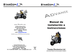
Helios Installation Manual Last Update: January 14th, 2009 COPYRIGHT © STARCOM SYSTEMS ALL RIGHTS RESERVED Distribution of substantively modified versions of this document is prohibited without the explicit permission of the copyright holder. Distribution of this work, or of a derivative thereof, in any standard (paper) book form for commercial purposes is prohibited unless prior permission is obtained from the copyright holder. DOCUMENTATION IS PROVIDED «AS IS» AND ALL EXPRESS OR IMPLIED CONDITIONS, REPRESENTATIONS AND WARRANTIES, INCLUDING ANY IMPLIED WARRANTY OF MERCHANTABILITY, FITNESS FOR A PARTICULAR PURPOSE OR NONINFRINGEMENT, ARE DISCLAIMED, EXCEPT TO THE EXTENT THAT SUCH DISCLAIMERS ARE HELD TO BE LEGALLY INVALID. Contact Information: http://ww.StarcomSystems.com The Hardware Module – Helios ii Simulation Kit Manual Table of Contents Chapter 1 Starcom System Overview .............................................. 1 The Hardware Module – Helios ........................................................ 2 Basic Helios Logic States ............................................................. Arming and Disarming the Helios ................................................. Communication with the Helios .................................................... Helios Tracking Modes ................................................................ 3 3 3 4 The Communication Module ............................................................. 4 Computer Requirements ............................................................. 5 The User Interface Module ............................................................... 5 Chapter 2 Helios Alarm System ..................................................... 7 Chapter 3 Helios Pin Allocations........................................................... 8 Chapter 4 Installing the Helios........................................................... 11 Safety and Wiring Considerations .................................................. 12 Positioning the Helios Optimally .................................................... 14 Tools Required for Installing the Helios......................................... 15 Before Installing ............................................................................. 15 Installing the Helios........................................................................ 15 Connecting External Relays to Enable Helios Functions .................. 16 Fuel Management...................................................................... 20 Chapter 5 Helios Accessories ............................................................. 21 Remote Devices .............................................................................. 21 Dallas iButton ........................................................................... 21 Remote Control ........................................................................ 23 Keypad .................................................................................... 25 Transponder ............................................................................. 27 Hands Free Kit .......................................................................... 28 Net-960E Mobile Data Terminal .................................................. 30 Temperature Sensor .................................................................. 35 Bluetooth Adaptor ..................................................................... 36 Chapter 3 Helios Product Line ..................................................... 37 Appendix 38 Table of Contents Cellular Phones Commands Helios ................................................. 38 Helios Hyper Terminal Commands ................................................. 39 i Simulation Kit Manual Chapter 1 Starcom System Overview The Starcom Helios is the mobile component of Starcom’s advanced vehicle tracking and fleet management system. The system uses advanced software algorithms for field tracking of vehicles and provides customers with a selection of real-time information about the tracked vehicle. Due to its versatility, you can use the Starcom system for any of the following applications: Sending real-time text messages to vehicle owners Protecting vehicles from theft Securing domestic and business premises Managing business enterprises Managing large databases, for example, population statuses and digital maps Tracing vehicles and calls The Starcom system consists of: The mobile unit – Starcom location control unit – Helios The communication layer of the cellular network The user interface, consisting of: Web application Control center software The Hardware Module – Helios 1 Simulation Kit Manual The following figure describes the components of the Starcom System. Figure 1 Starcom System Overview This manual describes how to install the Helios and touches on other system components only as required by the Helios. The Hardware Module – Helios The Helios integrates a GPS receiver and a GSM or CDMA cellular network modem. It provides a complete vehicle security alarm and fleet management solution. The twoway communication modem, based on existing wireless infrastructure, makes it possible to deploy the system with immediate and full functionality around the world. The modem enables the Helios to communicate via the GPRS/1x or the SMS channel and to receive and send status and location data. The built-in alarm system monitors the vehicle at all times and alerts the Starcom Control Center software in the case of theft or distress. After installing the Helios, you can reprogram its parameters remotely and send commands to perform multiple functions. You can integrate various accessories into the Starcom system, for example, text terminals, temperature sensors, accident/shock detectors, Bluetooth devices, and transponders. For detailed information on the available accessories, refer to Chapter 5 Helios Accessories on page 21. The Hardware Module – Helios 2 Simulation Kit Manual Basic Helios Logic States The Helios is always in one of four following alarm logic states: Idle – The state of the Helios when the engine is on. Garage – The alarm system is disabled for a predefined period of time. This is useful, for example, when the vehicle is undergoing maintenance. Silent Delay – The Helios enters this state if triggered while in the Armed state. In this state, only the blinkers are activated. After a predefined period of time has elapsed in Silent Delay mode, the Helios enters Alarm Triggered mode. Alarm Triggered – The system activates the siren. Armed – The immobilizer is activated and the engine is off. The alarm system is active and ready. Arming and Disarming the Helios There are six ways to arm and disarm the Helios: Remote Control (with or without code) – The simplest way to actively arm or disarm the Helios. Keypad – The control center can identify the vehicle driver by the code used. This provides an extra layer of security. Dallas – Press the Dallas iButton against the Dallas socket. The control center can identify the vehicle driver by which Dallas iButton is used. This provides an extra layer of security. Over-the-Air Command – Use Starcom software to arm or disarm the Helios with a remote command. Disarm from Input – Turning the ignition key disarms the Helios. Passive Arming – The Helios is automatically armed when a predefined period of time has passed after the engine was switched off. Communication with the Helios The Helios is always ready to receive an SMS text message command. By default, it attempts to connect to the GPRS network once. After succeeding, it remains connected and sends test transmissions (ping) via GPRS. The size this message is 50 bytes (or 1 kB in 20 transmissions), not including the TCP/IP headers. Important Note: To enable constant tracking of the Helios’s location and status, use the Tracking command. The Hardware Module – Helios 3 Simulation Kit Manual Helios Tracking Modes The Helios enables you to monitor vehicles at constant intervals or continually (this is necessary, for example, in a car chase). The following three tracking modes are available: SMS Tracking – The Helios transmits at regular intervals in any available communication channel (either SMS or TCP/IP). If no communication channel is available, the unit saves the message until coverage is resumed. The shortest interval available per message is one minute. Roaming- This mode useful for pass country borders, the Helios transmits at regular intervals that customized according to your requirements (via TCP/IP channel or SMS). The Helios communicates with the local cellular operator of the country it located. GPRS Tracking – The Helios transmits up to once every ten seconds. GPRS Tracking is only available if the unit is logged in to the TCP/IP network. If the message cannot be sent, it is discarded. This mode can be used for tracking a vehicle during a car chase. The Communication Module Communication between the Helios and Starcom software is performed through the GPRS channel (for GSM networks) and 1x (for CDMA networks) or the SMS channel. The following communication protocols are used: TCP/IP, SMPP, direct cable connection, private network, and the UDP protocol for external applications. SMS Channel – Can be implemented in two ways: Through a terminal unit connected to the server computer, or, in a network with many Helios units, through the SMPP protocol. SMPP protocol enables the system to receive SMS messages directly and enables sending SMS messages to mobile network devices. TCP Channel (GPRS or 1x) – The Helios connects to the network to send data (either through the Internet or through a private network) and uses the TCP protocol to send its data and receive commands from the Routing application. Private Network – When there is a large number of Helios units in your Starcom network, it is recommended to establish a private network with the cellular operator. This enables all the Helios units to connect directly to the operator's Routing application instead of connecting through the Internet. The private network facilitates the fast flow of information, eliminates much noise, blocks viruses, and lowers costs. The private network can be implemented either by setting up a dedicated communication line or a VPN (Virtual Private Network) with the cellular company. The Routing Application – This is the core of the Starcom communication system and is used to control the mobile network and the LAN/WAN simultaneously. It supports receiving data messages from GPRS/1x and SMS channels and from large numbers of GSM or CDMA units at the same time. The Routing application is installed on a computer that functions as the system server. It is the communication center for all the incoming and outgoing transmissions. The Communication Module 4 Simulation Kit Manual The Helios communicates directly with the Starcom operator local Routing application. When it connects to the GPRS network, it searches for the Routing application. Once the connection is made, communication flows in both directions. The Routing application can also use SMPP and modem terminals to communicate with the Helios units through SMS and send SMS notifications to clients. Typically, the Helios units have a second IP address to use as a backup in case of routing difficulties. A third party applications interface is available (EAI) for routing. The EAI can work with external applications either via UDP or TCP. Computer Requirements Your system server must meet the following minimum requirements to run the Routing application: Hard Drive: 200 GB The computer must be connected to the Helios main unit 24 hours per day and 7 days per week for enable the SMS transmission. RAM: 512 MB Microsoft® Windows 2000/XP/Vista Com Port (RS232) Internet Connection The computer must be able to accept incoming TCP/IP connections on ports 232 and 6600 and an additional port selected by the client. Note: The computer must run 24 hours per day and 7 days per week. The User Interface Module The User Interface consists of the following applications: Installer Application – Ensures correct installation by means of automatic testing for installation control. The program does not permit incorrect installation, prevents false alarms, and ensures customer satisfaction. The application enables programming of all parameters either via the RS232 cable connection or by wireless transmission. The Installer application is provided together with the Evaluation Kit and helps the operator learn the system functions, including programming via RS232 and remotely testing the various features, such as mileage readings from the odometer and by GPS and activating the gradual stop feature. Control Center Program – Supports 24/7 security control. The application enables operators to respond in a timely and professional manner to routine or emergency situations. The operators using the application follow a predefined set of procedures and respond as quickly and efficiently as possible to the incoming security events, may they be theft, accident, or another emergency situation. The Starcom Control Center application has a multi-language interface. It provides a predefined set of procedures to handle essential tasks such as: Emergency Calls – Theft, emergency button, and accidents, while taking into account the vehicle location and emergency services in place. The User Interface Module 5 Simulation Kit Manual Procedures Support – Matching the software to the local procedures according to the event type and individual client requests enables quick response for emergency situations. Database Management – Building and maintaining of databases that include: Clients, installers, personnel, and more. The software has the ability to sort the databases and information by subject and filters. Replay from Logs – The replay can be viewed on a map along with the vehicle status or on the reports that show trip and driver details. Information Management – Easy and friendly presentation of information for quick initial response. Ordering by priorities defined by the client, sending the information to another division in the organization, receiving information from the vehicle's sensors and visual display of any information from the vehicle. Reports – Producing reports based on the system information with a wide variety of filters, such as: Event summary reports, marketing reports, and technical reports. You can also create new reports. Starcom Online Web Application: The Web-based Fleet Management Application – An advanced tool for real time monitoring, tracking, and reporting. Starcom Online offers: Simple and user-friendly interface with many built-in fleet applications. Multiple options for production of activity reports. Starcom Online can be fully customized to be used with the local Starcom operator corporate branding, including colors, title, logo, and language. Real time alerts on deviation of vehicles and drivers from predefined work schedules. You can redirect alerts directly to the fleet manager's cellular phone or e-mail account. Control and support Starcom hardware, including: Geo fencing function, route control, speed alerts, analog and digital input controls, mileage reading (via the GPS), driver identification, commands via the client personal mobile phone, and a wide range of reports. The User Interface Module 6 Simulation Kit Manual Chapter 2 The User Interface Module Helios Alarm System 7 Simulation Kit Manual Chapter 3 Helios Pin Allocations The following figure describes the pin numbers in the Helios J1 connector. Use it as an aid to wiring Helios. Figure 2 J1 Connector Pin Numbers The User Interface Module 8 Simulation Kit Manual Wire the Helios J1 connector according to the following table of electrical connections. Table 1 Helios Pin-out Description Pin Function Number Color Designation Notes 1 Immobilizer and/or Blue Gradual Stop Output (-) Install with an external relay. Refer to Immobilizer and Gradual Stop on page 16. 2 Door Unlock Gray Output (-) Install with an external relay. Refer to Locking System on page 17. 3 RS232 TX Orange/Blue Communication Enables direct communication with a PC. The wire bundle provides a Molex connector. 4 Key (Ignition) Yellow Input (+) Indicates the vehicle ignition state. 5 Main Power 12V Red Power Supply Main +12V supply. Protected by a 5A fuse. 6 GND Black 7 Key Pad/Dallas Blue/White Communication The wire bundle provides a Molex connector. 8 Emergency Button White Input (-) 9 Microphone (+) Orange Audio Hands free connection kit. The wire bundle provides a Molex connector. 10 Speaker (+) Violet Audio Hands free connection kit. The wire bundle provides a Molex connector. 11 Analog 1 Yellow/Blue Input (-) Used for fuel consumption. 12 CAN High Black/Gray CAN bus connection 13 Door Lock Gray/Orange Output (-) 14 Arm Orange/White Input (-) 15 RS232 RX Blue/Black Communication 16 Door Green Input (-) 17 Disarm Pink Input (-) Alarm system disarming input. 18 GND Black 19 Siren/Vehicle Horn Red/Black Output Install with a relay (according to the vehicle voltage 12V or 24V). 20 Odometer White/Black Pulse Counting Input (+) Connect to pulse generator.* 21 Microphone (-) Green/Red Audio Hands free connection kit. The wire bundle provides a Molex connector. 22 Speaker (-) Blue/Red Audio Hands free connection kit. The wire bundle provides a Molex connector. 23 Analog 2 Violet/White Input (-) 24 CAN Low Gray/Blue CAN BUS connection Install with an external relay. Refer to Locking System on page 17. The wire bundle provides a Molex connector. *The odometer input informs the system whether to measure mileage by counting odometer pulses or by calculating the distance traversed by the vehicle using GPS. The odometer can count pulses from any type of pulse generator. The User Interface Module 9 Simulation Kit Manual The following figure shows how to connect all the auto components to the Helios. Figure 3 Auto Components Block Diagram The User Interface Module 10 Simulation Kit Manual Chapter 4 Installing the Helios Warning: Failure to closely adhere to all installation instructions may result in system malfunction and ultimately compromise the reliability of the entire system. It is assumed that installers are familiar with vehicle wiring and auto electrical devices. This chapter contains a selection of wiring options from which to select. Select the options best suited to your application. Avertissement : Le non-respect de toutes les instructions d’installation peut causer un fonctionnement défectueux du système et par la suite affecter la fiabilité du système entier. Il est présumé que les installateurs sont familiers avec le câblage du véhicule et les appareils auto électriques. Ce chapitre inclus une section des options de câblage à choisir. Choisissez l’option la plus adaptée à votre application. Warnung: Nichtbefolgen der Installationsanweisungen kann zu Betriebsstörungen im System führen und somit die Verlässlichkeit des gesamten Systems gefährden. Es wird vorausgesetzt, dass die Person, die es einsetzt mit den Kabeln des Fahrzeugs und den elektrischen Geräten vertraut ist. Dieses Kapitel enthält mehrere Verkabelungsoptionen, aus denen Sie wählen können. Wählen Sie die Optionen, die sich am besten für Ihre Anwendung eignen. The User Interface Module 11 Simulation Kit Manual Safety and Wiring Considerations Warning: Always adhere to safety instructions to prevent possible injury and avoid damage to existing vehicle systems. Before beginning an installation, disconnect the vehicle battery. Notify the client that this erases the memory of all auto systems. These will have to be reprogrammed. Test wiring only using a LED test-lamp or voltmeter. Using other types of testlamps may cause high output currents and significant damage to the vehicle's electrical systems. Solder all connections created during installation and insulate them using electrical insulation tape and/or insulation sleeves. Twisting wires together without soldering them can result in loose connections and serious faults. There is the danger of explosion if the battery is replaced incorrectly. Replace the battery only with the same or equivalent type recommended by the manufacturer. Dispose of used batteries according to the manufacturer's instructions. Take special care to avoid damage to the cables of the vehicle's security systems, for example, vehicle computer and air bags. Take note of this when testing voltage using a voltmeter or test-lamp to prevent undesired system activation. Only trained and qualified personnel should be allowed to install, replace, or Service this equipment When drilling in the vehicle, verify that there are no cables in the vicinity. Failure to do so may result in severe damage. Avertissement: Respectez toujours les instructions de sécurité afin de prévenir et éviter un dommage aux systèmes existants du véhicule. Le danger d’explosion existe lorsque la batterie est remplacée incorrectement. Remplacez la batterie seulement avec la même ou un type équivalant recommandé par Starcom Systems. Déposez les batteries usées en respectant les instructions du fabricant. Testez le câblage seulement en utilisant une lampe-test LED ou voltmètre. L’utilisation d’autres types de lampes-teste peut causer la production du courant élevé et un dommage significative pour le système électrique du véhicule. Soudez toutes les connexions crées durant l’installation et isolez les en utilisant un ruban d’isolation électrique et / ou une manche d’isolation. Enserrez les câbles ensemble sans les souder peut se terminer par la perte des connexions et des graves défauts. Lorsque vous perforez dans le véhicule, vérifiez qu’il n’y a pas des câbles à proximité. Faites attention de ne pas endommager les câbles du système de sécurité du véhicule comme par exemple l’ordinateur du véhicule ou l’Air bag. Safety and Wiring Considerations 12 Simulation Kit Manual Seules les personnes formées et qualifiées ont l’autorisation d’effectuer les installations, remplacer ou servir cet équipement Avant de commencer une installation, déconnectez la batterie du véhicule. Informez le client que ceci effacera la mémoire de tout le système auto et devra être reprogrammé. Warnung: Halten Sie sich immer an die Sicherheitsanweisungen, um mögliche Verletzung und Schäden an den vorhandenen Systemen des Fahrzeugs zu verhindern. Trennen Sie die Verbindung der Fahrzeugbatterie, bevor Sie mit der Installation beginnen. Teilen Sie dem Kunden mit, dass die Speicher aller Systeme des Autos gelöscht werden. Diese müssen neu programmiert werden. Verkabeln Sie probeweise mit einer LED-Testlampe oder einem Spannungsmesser. Das Verwenden von anderen Testlampenarten kann zu hohem Ausgangsstrom führen und die elektrischen Systeme des Fahrzeugs beträchtlich beschädigen. Löten Sie alle Verbindungen, die während der Installation erstellt wurden und isolieren Sie sie mit Isolierband und/oder Isoliermanschetten. Wenn Kabel nur verdreht und nicht gelötet werden, kann dies zu lockeren Verbindungen und ernsten Fehlern führen. Wenn Sie im Fahrzeug bohren, stellen Sie sicher, dass sich keine Kabel in der Nähe befinden. Sollten Sie dies nicht tun, können schwere Schäden die Folge sein. Achten Sie insbesondere darauf nicht die Kabel des Sicherheitssystems des Fahrzeugs zu beschädigen, beispielsweise des Computers und des Airbags des Fahrzeugs. Beachten Sie diese, wenn Sie die Spannung mit einem Spannungsmesser oder einer Testlampe testen, um eine ungewünschte Aktivierung des Systems zu vermeiden. Nur ausgebildetes und qualifiziertes Personal sollte diese Ausstattung installieren, ersetzen oder warten. Es besteht Explosionsgefahr, wenn die Batterie nicht richtig ersetzt wird. Ersetzen Sie die Batterie nur mit dem gleichen oder gleichwertigen Typ, wie der vom Hersteller empfohlene. Entsorgen Sie gebrauchte Batterien nach den Anweisungen des Herstellers. Safety and Wiring Considerations 13 Simulation Kit Manual Positioning the Helios Optimally Do not install the Helios beneath metal parts, for example, under a shelf supporting loudspeakers. To maintain high-quality reception, it is highly recommended to install the Helios in a location that provides an uninterrupted line-of-view with the sky. Consider any of the following locations for installing the Helios: Within the vehicle dashboard Near to the glove compartment Behind instrument panel In the center console Under the steering column Ensure that the Helios is not near to heat sources, water pipes, or the vehicle computer. The following figure illustrates some of the possible installation locations. Dashboard Glove Compartment Instrument Panel Steering Column Central Console Figure 4 Installation Locations Positioning the Helios Optimally 14 Simulation Kit Manual Tools Required for Installing the Helios The following tools are required for installing the Helios: Electric drill and/or screwdriver Cone drill Adapter for Phillips (cross-head) screws Phillips, flat-tip, and star screwdrivers – various sizes Wire cutter Test-lamp and/or voltmeter (use of voltmeter is preferred and recommended) Electrical insulation tape Regular and drilling head screws Insulation sleeve or soldering iron and solder Before Installing Run the Installer application and click Technical > Unit Status to verify if the type and model of vehicle-under-installation appears in the Wiring by Models table. Study the available information before proceeding. If the vehicle type is not listed in the table and you are in possession of the data required for installation, add all the pertinent information. For improved system security, it is recommended to vary the installation location randomly for each successive installation. Confer with the client as to the location of the keypad, Dallas button, emergency button, and other service buttons. Installing the Helios It is very important before installing the Helios unit in vehicle to run the Helios Wizard for latest Firmware version update and connectivity test (TCP Test). Use alcohol to clean the surface to which you have decided to attach the Helios. Secure the Helios in its chosen location using cable ties and ensure proper concealment of all wires. Connect all the required wires in the cable to the Helios connector before connecting the connector to the Helios. Tools Required for Installing the Helios 15 Simulation Kit Manual Connecting External Relays to Enable Helios Functions This section provides guidelines on how to wire the Helios output pins that require the addition of an external relay. This is not an exhaustive discussion and there are many possibilities – you should consider which option is best before commencing. Note: Check the vehicle voltage (12V or 24V) before beginning work and provide relays of the correct voltage. Immobilizer and Gradual Stop The Helios can bring the vehicle to a gradual stop if necessary. For example, if the vehicle is reported as stolen, the control center can issue a Gradual Stop command. When there are no alarms, the Immobilizer/Gradual Stop pin (#1) grounds the coil (#85) of the external relay. In this case, the relay powers the vehicle starter or fuel pump (via pin #87). When a Helios alarm is activated, the Immobilizer/Gradual Stop pin (#1) toggles the ground to the relay coil. As the duty cycle of pin 1 changes, the coil becomes gradually deactivated for longer and longer intervals until it is fully disconnected from ground. Consequently, the starter or fuel pump gradually becomes inactive, bringing the vehicle to a gradual stop. Figure 5: Immobilizer and Gradual Stop Wiring Scheme Installing the Helios 16 Simulation Kit Manual Siren The Helios can sound the vehicle siren. When wiring the Helios siren function, you can add an external siren or you can use the vehicle’s own horn. Note: The vehicle horn may use a large current and quickly deplete the vehicle battery. When there are no alarms, the Siren pin (#19) disconnects the coil (#85) of the external relay from ground. In this case, the relay disconnects the siren (which is connected through pin #87 of the relay (#87). When a Helios alarm is activated, the Siren pin (#19) grounds the relay coil. As a result, the siren is powered through the relay and sounds. Figure 6 Siren Wiring Scheme Locking System Before making any changes to the vehicle wiring, verify which type of locking system is in use. If you can identify the location of the locking engine and gain access to its terminals, you may be able to make a direct connection without adding external relays. (–) (–) Locking In this locking method, a negative pulse activates the locking mechanism and the next negative pulse activates the unlocking mechanism – this is called (–)(–). It is also possible to use (+)(+). For vehicles with (–) (–) locking systems, you can wire the Helios without adding any external relays, as follows: 1. Connect Helios the Lock pin (#12) to the locking engine Lock terminal. Installing the Helios 17 Simulation Kit Manual 2. Connect the Helios Unlock pin (#1) to the locking engine Unlock terminal. Figure 7 Wiring the (–) (–) Locking System without External Relays If you cannot gain access to the locking engine, you can use external relays and connect to the existing wires that lead to the locking engine. The following figure describes this connection. Figure 8 Wiring External Relays for (–) (–) Locking Installing the Helios 18 Simulation Kit Manual Serial Locking This method requires the addition of two external relays. Wire them as follows: Figure 9 Wiring External Relays for Serial Locking Arm/Disarm You can connect the Helios Arm/Disarm function either as a standalone system or in conjunction with the existing system. Standalone Arming Arming is performed by passive arming, remote control, or transponder. Disarming is performed by unlock, key pad, remote control, or transponder. Connecting to the Existing Arm/Disarm System Locate the existing alarm system brain and connect the Helios Arm pin (#14) to the alarm system brain Arm pin with a diode. Also, connect the Helios Disarm pin (#17) to the alarm system brain Disarm pin with a diode. Note: If the vehicle’s existing alarm system uses (+) (+) commands, insert external relays to swap the logic to (–) (–). Installing the Helios 19 Simulation Kit Manual Fuel Management The fuel tank in passenger vehicles it is generally located under the passenger back seats. Typically, it has three or four wires, as follows: Fuel Pump – When the engine is running, you can measure 12V on this wire. Ground. Fuel Gauge – Analog wire. When the engine is running, you can measure 0 – 8V depending on the fuel level. This voltage may vary between different vehicles and requires calibration. Fuel Warning LED – Digital wire. Not present in all vehicles. When the fuel level falls below a critical level, this wire lights a warning lamp on the dash board. Connecting your testing lamp to this wire also causes the warning lamp on the dash board to light. Gas Tank Level To connect the gas tank level pin: 1. Identify the fuel gauge wire analog wire. To verify that you have found the correct wire, turn off the main electrical switch and cut the wire. If this is the fuel gauge wire, the fuel gauge on the dash board will show a maximum fuel level. 2. Connect the fuel gauge wire to the Gas Tank Level pin (#11) – Analog 1 Input. Warning: Do not connect a negative voltage to the fuel pump as this may cause damage. Installing the Helios 20 Simulation Kit Manual Chapter 5 Helios Accessories Remote Devices Dallas iButton The Dallas iButton is used to disarm the Helios, activate Garage mode, and identify drivers. You can program up to 50 Dallas iButtons into the Helios memory for identifying drivers. Figure 10 Dallas iButton Installing the Dallas iButton To install the Dallas iButton remotely: 3. Place the Dallas socket on the dashboard and connect the black wire (–) to ground and the gray one to the Key Pad/Dallas pin (#7) of the Helios . 4. Send a command of "Learn Dallas iButton", using an Installer application. 5. Choose Dallas code memory location, according to "Drivers ID" tab in Helios Parameters window. 6. Choose an output to be triggered when pressing the bigger button. Remote Devices 21 Simulation Kit Manual 7. Send a command and attach the Dallas to its socket. 8. A green light acknowledges the Dallas has been programmed. To program a new Dallas key using Starcom Simulator: 1. Select a memory location for the Dallas iButton. 2. Click Send. The simulator LED lights up. 3. Insert the Dallas iButton in its socket for the duration of the programming (until the LED turns off). 4. Remove the Dallas iButton. Important Note: Pay attention to place the switch to DALLAS (DLS) position. DALLAS Figure 11 Dallas iButton Switch Remote Devices 22 Simulation Kit Manual Remote Control The remote control is used for arming, disarming, LED Locking, and unlocking the vehicle. You can program up to two remote controls into the Helios memory. Arm/Disarm Button Siren Button Figure 12: 2-Button Remote Control To program a new Remote Control: 1. Please download the Installer application update from this link: http://www.starcomsystems.com/1119bo/ , then update the unit`s firmware. 2. Big button: used for Arm/Disarm Small button: used for emergency. 3. Go to: Helios parameters -> Hardware tab -> mark Remote Control options As displayed, and Send them to the unit. Remote Devices 23 Simulation Kit Manual 4. Go to: Unit status window-> Learn Remote Control-> set the requested settings-> send. Memory location refers to the Drivers ID section at Helios parameters: When the unit has learned the Remote, you will see the updated code in appropriate place. To arm/disarm the unit: Press the Arm/Disarm button. 5. Now you can check the Remote Control functionality -> try to Arm/ Disarm using the button and see if the signaling output changes. Remote Devices 24 Simulation Kit Manual Keypad The keypad is used to arm and disarm the Helios and for driver identification. You can program up to 50 keypads into the Helios memory. Figure 13 Keypad To arm the system: Enter (*) and press four times on the 4 button. To disarm the system: Press (*) and enter your PIN code. The key pad buzzer sounds to confirm the operation. To garage mode: In Helios IDLE state, press (*) and four times on the 5 button. To change/add the keypad PIN code: Note: In this procedure, you are editing the default codes. 1. In the Installer application, click Technical > Helios parameters > Driver IDs. 2. Click new and insert driver personal code (four digits). 5. Click Send Changes to complete programming. Remote Devices 25 Simulation Kit Manual The keypad LED provides the following indications. Table 2 Keypad Indications State of Helios State of Keypad LED Idle Extinguished Alarm Armed Blinking every 2 seconds for 2 seconds Silent Delay Blinking twice every 2 seconds Alarm Triggered Blinking every 1 second for 1 second Garage Mode Constantly Note: The theft indicating transmission will be initiated in the end of Alarm Triggered state. Important Note: Pay attention to place the switch to Keypad (KYPD) position. KEYPAD Figure 14 KEYPAD Switch Remote Devices 26 Simulation Kit Manual Transponder The transponder automatically arms or disarms the system when it comes within or leaves the range of the system. Figure 15 Transponder The Transponder system is comprised of the receiver, connected to the Helios, and the remote transponder. Installing the Transponder To install the transponder: 1. Connect the red wire (pin 1) to +12V. 2. Connect the black wire (pin 2) to ground. 3. The gray wire (pin 12) is used to arm the Helios. Connect it to the Helios Arm pin (#18). 4. The blue wire (pin 11) is used to disarm the unit. Connect it directly to the Helios Disarm pin (#17). 5. The violet wire (pin 6) is used to avoid false disarms. Typically, connect it to the ignition. In this case, when the receiver receives +12V after receiving a valid transmission, it does not send an arm command even if the transponder signal is lost for more than 45 seconds. 6. The yellow wire (pin 5) is used to couple transponders. Typically, it remains unused because the transponder and receiver are shipped already coupled. If you wish to couple a new transponder, use the following procedure: a. Short the yellow wire to ground. b. After three seconds the receiver module LED turns on. c. Press the transponder button repeatedly. When the receiver module has coupled with the transponder, the LED blinks (turns quickly off and back on steady). Should the need arise to reprogram the receiver to be associated with other transponders, it is possible to perform coupling of transponders remotely and without having to rewire the system: Connect the yellow wire to one of the digital outputs of the Helios (for example, pin 1 of 6 pole connector). Remote Devices 27 Simulation Kit Manual Hands Free Kit The Helios voice function enables you to communicate with the control center or with any fleet station by commanding the hand set. When the channel is open, the control center can hear whatever transpires in the vehicle. Speaker LED Indicators Earphone To Helios Power Microphon e Figure 16 Hands Free Kit To activate the handset: 1. Plug in the communication cable to the Speaker and to the HFK connector within the 24pin wire-bundle. Important to connect the black outgoing wire to Ground (-) connection. 2. If the power supply cable not used for connection to cigarette lighter, cut the lighter connector and release the internal red and black wires for (+) and (-) connections as following: Remote Devices 28 Simulation Kit Manual 3. Plug in the microphone cable. 4. Send a command of Voice Call from Starcom Online -> Map -> Commands -> enter a number for unit to dial -> Send. 5. The unit will start dialing that number using the Voice channel. Speaker – The speaker volume control is next to the earphone plug. Hands Free LED Indicator – This is constantly on. Microphone – The microphone must be located at least 50 cm from the speaker. Power LED Indicator – Indicates whether the hand set is active. The hand set is activated by a Voice Call command. Important Note: It is highly recommended to twist around the red and the black cables within the wire-bundle for noise filtering effect and improving the voice quality. Figure 17 twisting the wires The hands free kit supports 12V only. To use in a 24V vehicle, power it from the cigar lighter receptacle (which supplies 12V in all vehicles). The modem disconnects automatically one minute after disconnecting a call. You may connect the hands free kit to the Helios while the unit is powered up. The hands free kit connects to a 4-pin Molex connector on the Helios J1 connector wire bundle. TCP/IP communication is not possible while the voice channel is active. Set hands free kit volume as low as possible when using the Helios as an emergency application. This is because the hands free kit creates a dialing tone whilst receiving phone calls. When the hands free button is in the OFF position, the hands free kit cannot hear the caller, but the caller is able to hear what is going on in the vehicle. Remote Devices 29 Simulation Kit Manual Net-960E Mobile Data Terminal The Net-960E is a programmable Mobile Data Terminal (MDT) that can be installed in vehicles. It is designed to withstand the tough vehicle environment including extreme temperatures, providing the reliability required for critical mobile data applications. The current firmware version is v5.09. The Net-960E displays incoming messages and can initiate outgoing messages between the vehicle and the fleet manager. It uses the English language by default. You can add text templates in other languages using the Installer application (MDT Canned Add/Del or Reply Add/Del). To add a template: Write a template and send it to the MDT using the CannedAdd command. To remove a template: Write the exact template and send it to the MDT with CannedDel command. The same procedures apply to the reply templates list. The NET-960E is fully integrated with Starcom fleet management software and can be used to send and receive messages from the Starcom Online Web application. Figure 18 Net-960E Assembling the Net-960E To mount the Net-960E: 1. Insert the rubber mounting pads on the inside of the bracket and thread the rubber pins through any of the three parallel holes on each side. 2. Rotate the mounts so the holes in the center of the mounts align with the parallel holes in the bracket. 3. Hold the terminal between the rubber mounts, attach the side screws, and ensure the terminal is firmly in position. Do not over-tighten. Remote Devices 30 Simulation Kit Manual Rubber Mounting Pad Rubber Mounting Pin Figure 19 Mounting the Net-960E Parallel Mounting Holes To attach the control box: 1. Connect the Net-960E control box cable (9 pin connector) to the SER 1 connector on the Net-960E. 2. Connect the Net-960E control box cable (RJ 45) to the RS232 input pin (#15) on the Helios. 3. Connect the Net-960E power and ground to the vehicle battery only after you have powered up the Helios. Turn the power switch on the control box (PWR) to ON. MDT Activation: Before activating a Mobile Data Terminal, please change the communication rate between the Helios unit and the MDT. Using an Installer application, read the unit's parameters, approach "Hardware" tab, check the box of "Use 57600 baud rate" and send the new parameters to the unit. Remote Devices 31 Simulation Kit Manual Note: It is important to restart the unit after changing the Baud rate; otherwise the change won't be updated. Starcom Online: In order to send and receive text messages using Starcom Online application, update Helios unit as a text Terminal. Log on to Starcom Online and approach the Resources section. Click on the unit's number and update the field of "Terminal" to "Text". From now on, the command of "Send Text" will be available in the commands list at Map section. Receiving Text messages: Go to Monitor screen > Settings, and create a New Alert to alert you on incoming Text transmissions. After updating the new text alert - you can use the Monitor screen to see all the incoming Text messages from the units. Operational Indications and Commands MSG LED – Blinks slowly when there is one new message and blinks fast if there are multiple messages to be read. ACK LED – Blinks when a message has been transmitted and the Net-960E is waiting for the first level acknowledgement. In normal operating conditions, this state is too short to be noticed. When the first acknowledgement is received the Net-960E waits for the host level acknowledgement and the ACK LED is on. CLR – Enables you to clear the screen and return to the main menu. F2 TEXT – Enables you to enter an alphanumeric data string. The 1 key is used for a space in alphanumeric data entry. In order to enter a message, use the alphanumeric keys and press F2 again. In order to clear a single character (backspace), rotate the navigation dial counterclockwise. F3 VIEW – Displays the incoming messages (received from the host). Scroll with the navigation dial. The Net-960E can store up to 10 incoming messages. The next message (number eleven) overwrites the first message, and so on. F4 PEPLY – Opens a list of messages. Scroll to the desired message with the navigation dial, and press the dial. You can update the messages with the Installer application. F5 CNTL – Opens the control menu. You can configure backlight, contrast, sound, fonts, and more. When in control mode, use the numeric keypad as follows: Key 1 – Toggles the screen backlight. ENT – Enables you to access functions using the navigation dial. F1 MSG – Displays a list of pre-defined (canned) messages. Scroll through the list using the navigation dial and press the navigation dial or ENT to transmit the selected message. Pressing the navigation dial again toggles between the list and single item display modes. Key 2 – Sets the sound tone. Remote Devices 32 Simulation Kit Manual Key 3 – Toggles the sound – This is not active in the demo unit. Key 8 – Enables you to set the screen contrast. Key 4 – Enables you to configure fonts for incoming and outgoing messages. You can also configure a limit for the number of characters in messages (the maximum is 220 characters). Key 9 – Toggles the Net-960E on or off. F6 I/O – Displays the state of the inputs and outputs. Notes: The Demo unit is a unit with the basic Net-960E functions and without any customizing process. For example, the sound tone function is not active and outgoing messages are limited to 33 characters and incoming messages are limited to 40 characters. After two minutes of inactivity, the screen backlight turns off. It automatically turns on with new incoming messages or when any key is pressed. The Net-960E display driver can display text using character fonts of 8, 6, 5, or 4 pixels width. It can display 30, 40, or 48 characters per line. Several fonts as well as text attributes and character doubling may be intermixed on the same screen. There is no option to scroll within the message being displayed. Net-960E Specifications Memory Flash – 128 kB to store system and application software, inbound/outbound canned messages, or forms RAM – 128 kB of data and system memory Communication Main – RS232 serial port, up to 57,600 kBPS, connected to DB9 connector Secondary – RS232 serial port, up to 57,600 kBPS, connected to RJ11 connector Multiplex – Each port can be multiplexed between an internal and external connector Control Signals Two inputs and two outputs at the automotive voltage level, connected to a DB9 connector Or One input and one output at the automotive voltage level and one input (CTS) and one output (RTS) at RS232 voltage level Display 240x64 graphic LCD with LED backlight Variable font sizes. Maximum – 10 lines of 60 characters in a 7x5 standard matrix FSTN technology at contrast ratio of 7:1 Remote Devices 33 Simulation Kit Manual Programmable Keyboard 12 Alpha Numeric keys (cell phone style) 6 Programmable function keys Special navigation knob Backlight for all keys Indication Lamps Activity LED Alert indicators LED Buzzer Audible alerts Programmable frequency pitch and duration Power Direct car battery connection – 8V–18V (for 24V vehicle, use a converter) Current: Idle–18 mA. Active – 200 mA Environment Operating temperature: –20°C to +70°C (–4°F to +158°F) Storage temperature: –20°C to +80°C (–4°F to +176°F) Dimensions Length – 200 mm (7.87") x Width – 82 mm (3.22") x Depth – 38 mm (1.5") Remote Devices 34 Simulation Kit Manual Temperature Sensor You can use the temperature sensor to measure the temperature when this information is important, for example, in an oil tanker. Figure 20 Temperature Sensor The temperature sensor is factory-fitted with a filter to which it connects with a shielded cable. The filter reduces environmental noise and measures temperature in the range –20°C to +40°C. Install the probe in the location whose temperature you wish to track. Note: The following figure shows how the filter is connected to the temperature sensor. Ground connections are marked by square shapes on the printed circuit board and positive signals by round shapes. Figure 21 Temperature Sensor and Filter Connections To calibrate the temperature sensor: 1. Using a thermometer calibrated by an approved laboratory, measure the temperature in the area of the vehicle whose temperature you wish to track. 2. Record the value registered by the temperature sensor. 3. Repeat steps 1 and 2 for three or four different temperatures. 4. Access Starcom Online and upload the values you measured. Starcom will send you a calibration update. Remote Devices 35 Simulation Kit Manual Bluetooth Adaptor The Bluetooth adaptor enables advanced connectivity using the Bluetooth standard. This enables the system components to transmit information such as the Installer application and navigation. It also enables interfacing between handheld computers (for example Palm Pilot and IPAQ) and the Helios. Bluetooth Specifications Bluetooth Protocol Standard: 1.2 Class: II 1 mWatt transmitter power Operating distance: 10 meters (without obstructions) Frequency band: 2.40 GHz – 2.48 GHz Power supply on pin 9 of RS232 connector Operating temperature: –20°C – 80°C Bluetooth Adaptor RS232 connector male connector (DTE) 12 to 30 volt power supply Reverse polarity protection Internal status LED Automatically sends \g to the Helios at power-up making it compatible with any portable navigator (tested with TomTom) Makes the Helios directly visible to installers without directly accessing it No drivers required Installing the Bluetooth Adaptor The Bluetooth device connects directly to the Helios cable (connect only the 9-pin connector), as follows: Connect INS 2 and 3 according to the standard Helios cable. Connect pin 9 to +Vcc. Connect pin 5 to GND (the Helios GND). When you search the adapter with a Bluetooth device (laptop, PocketPC, etc.), you will find GPDSAT. The key code is 1234. Remote Devices 36 Simulation Kit Manual Chapter 3 Helios Product Line The Helios product line comprises of the following units: Helios Basic Helios Logger Helios Advanced The following table describes the features of the different Helios units: Table 3 Helios Product Line Specification Helios Basic Helios Logger Helios Advanced GPS Built in Built in Built in GSM + ZIGBEE + + Optional Connector 5 pins, USB 24 pins, Molex 24 pins, Molex Accelerometer Optional Optional Built in + + Full fleet and full security functions. Can be used as stand alone alarm system The most advanced unit Canbus Use Track and trace basic functions Full fleet without GSM communication costs Advantage Quick installation Low cost Can be used as mobile unit Can be transferred between vehicles No communication and modem costs Configuring Cellular Phones 37 Simulation Kit Manual Appendix Cellular Phones Commands You can use a cellular phone to send commands to the Helios. You must first contact the Starcom Online operator and state the phone number from which you intend to issue commands. The control center will issue you with a phone number for the destination commands. To send SMS text message commands: Send an SMS text message in the following format: <COMMAND> <UNIT NUMBER> <STARCOM USERNAME> <STARCOM PASSWORD> For example, if your login credentials in Starcom Online are "starcom / starcom1" and the unit's number is 1234, you can activate the siren by sending a command: AS 1234 starcom starcom1 Note: Insert spaces between the command, the unit number, and the password. The following table defines the SMS text commands supported by the system. Table 4 Helios SMS Text Commands Command Description AS Activate Siren DS Deactivate Siren AL Activate Lights DL Deactivate Lights AI Activate Immobilizer DI Deactivate Immobilizer LD Lock Doors UD Unlock Doors AG Activate Gradual Stop DG Deactivate Gradual Stop AD LED On DD LED Off STAT Status Request Cellular Phones Commands 38 Simulation Kit Manual Terminal Commands Terminal commands enable you to control the Helios cellular modem via the RS232 connector. You can do this to test communication quality and solve installation problems. Notes: Preface all commands with a backslash (\) and end them with "Enter". You can be online and connect to the Hyper Terminal concurrently. All commands are case-sensitive. Table 5 Helios Hyper Terminal Commands Command Name Description tdm Cellular Mode Gives direct access to the modem. tdg GPS Mode Gives direct access to the GPS. tdr TCP Mode/Already in TCP Mode Connects to the TCP/IP network immediately. Terminal Commands 39 Simulation Kit Manual