1
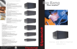
Big Bang
SpeakerCraft
®
Power Amplifiers
BB835
O w n e r ’s M a n u a l
Thank you for purchasing the SpeakerCraft BB835 power amplifier.
The BB835 contains the excellent performance and reliability that
SpeakerCraft products have been recognized for. The BB835 features the flexibility needed for demanding custom installation applications. It is ideal for use in home theater, stereo, multi-room, multizone and commercial applications. For best performance, please
carefully read the instructions in this manual.
Table Of Contents
Page
Features
FEATURES
Audiophile Design
Sophisticated design and superior internal components result in outstanding
sound quality, performance and long term reliability.
Advanced Protection
Each channel is individually protected. If the circuitry determines that a channel must be shut down for protection, a rare occurrence, only the channel
affected will be turned off. The other channels will continue to play. Once
conditions return to normal, the affected channel will be turned back on and
operate as normal.
2
Flexible Input Selection
Front Panel Diagram
3
Each of the 12 channels can be assigned a variety of source inputs. A dedicated input can be assigned to each channel. Each channel can also be configured to play common signals from the Bus or Auxiliary inputs. This provides
the flexibility needed in sophisticated custom audio installations.
Rear Panel Diagram
5
Bridging
System Design & Operation Considerations
7
System Design Examples
9
The power output of adjacent channels can be combined to provide extra
power when needed in certain areas. This is easily accomplished by flipping a
single switch.
Individual Channel Level Adjustments
Installation Considerations
19
Each channel has its own level adjustment. This allows the loudness of each
speaker to be perfectly matched to its area.
Installation
20
InstaLLock™ Connector Outputs
Simplify the connection of the speaker outputs by using SpeakerCraft’s
InstaLLock™ Connector, purchased separately. InstaLLock™ Connectors eliminate the hassle of connecting multiple wires onto the back of the amplifier.
Instead they can be easily connected to the InstaLLock™ Connector which is
later plugged into the back of the amplifier. InstaLLock™ Connectors can be
purchased from your SpeakerCraft Dealer.
Operation
24
Troubleshooting
25
Specifications
27
Multiple Power Modes and Output Trigger
28
There are three ways to turn the amplifier on: constant, trigger and audio
sense. This allows the amplifier to operate seamlessly as part of a sophisticated custom installation. A separate output trigger allows the amplifier to activate other components via a voltage trigger.
Warranty
1
2
Diagram 1 - Front Panel
Active LED indicates that the amplifier is working.
Master power switch. Turns off power
to amplifier and Power Mode Circuitry.
Protection LEDs indicate that either a fault
in the wiring, the speaker, or the amplifier
has caused the amplifier to shut down.
3
4
Diagram 2 - Rear Panel
Main bus inputs allow outputs from
receivers, CD players, TVs, or any
stereo audio sources to be amplified
across all channels for easy multiroom applications. Auxiliary inputs
allow an additional audio source to
be played on any channel that is
switched to AUX.
Bus outputs allow the
bus inputs to be sent
to other amplifiers or a
daisy chain without the
need for ‘Y’ cables or
splitters. Auxiliary outputs allow you to daisy
chain the input to
other audio sources.
Level controls for
each channel.
Bridging switch allows
you to easily double
the power output by
coupling two channels together.
Gold plated
individual channel
inputs allow you to
connect different
audio sources to
each channel.
One switch allows you
to select which stereo
Input Selection
input channel will play
switch allows you
through the speaker outto select between
puts: left, right, or left
the common bus
and auxiliary inputs, and right combined. If
switched to Left + Right,
or the individual
both input channels are
channel input.
combined.
Impedance switch is
used to select either 8Ω
or 4Ω.
The Power Mode switch is
used to toggle between three
different trigger methods to
power up the amplifier.
3-30V A/C or D/C input to
trigger power up with voltage
from another device, such as
a receiver.
12V output to turn on other devices when
amplifier is powered up. Connect to projector
screens, powered drapes, or other devices
with voltage triggers.
5
Binding posts allow the use of
stripped speaker wire, spade
connectors, or banana plugs.
3-Prong removable
power plug.
Fused AC input.
Plugs for InstaLLock™ connectors are
provided for easy connection of
speaker outputs. Requires optional
InstaLLock™ amplifier connectors to
be purchased separately.
6
SYSTEM DESIGN & OPERATION CONSIDERATIONS
To best understand system design and operation of the BB835 it is useful to
understand the following terms and features as they relate to the BB835.
Bus Input
Allows the signal from a source to be distributed to any of the 12 channels
on the amplifier.
Auxiliary Inputs
Multi-Room
A system design that plays the same source at the same time in all rooms. If a
change is made in one room, the same change takes place in all other
rooms. For example, if a listener changes from CD to Tuner in the bedroom,
the same change will be heard in the kitchen. Note: With the use of volume
controls or speaker switchers the volume of each room can be controlled separately of the other rooms.
Allows a the signal from a secondary source to be distributed to any of the 12
channels of the amplifier.
Impedance Switch
Select either 8Ω or 4Ω to maximize amplifier performance with a variety of
speaker loads. See the sections titled “Selecting the Impedance Setting” and
“Selecting Bridge Mode” in the “Installation” section for proper setting of this
switch.
Multi-Zone
A system design that allows different sources to be played in each room. A
change in one room can be made without changing the other rooms. For
example the CD player can be heard in the bedroom while the kitchen is
playing the tuner.
Bridging
Power Mode Selection
There are three ways to turn the amplifier on and off. Use the following list to
decide which mode will work best for your application. See Diagram 3
below.
1. Constant
The combining of 2 channels to create one mono channel. It is useful when
more volume is needed in a particular area.
Source
Use this selection when you wish to manually turn the amplifier on
and off by using the front mounted power button.
2. Trigger
Component, audio or video, that provides an audio signal. Examples are CD,
VCR, DVD, tape deck and tuner. The source provides the audio information
that is amplified by the BB835.
Channel
A distinct unit of the amplifier that provides output to one speaker. On the
BB835 the input to each channel can be configured to select from the BUS
INPUT, the AUX INPUT or that channel’s unique CHANNEL INPUT. Two adjacent channels can be bridged to provide higher power to one speaker.
Level Controls
Allows any of the channels to be adjusted independently to raise or lower the
output of each channel. This may be used to control the speaker output in
order to balance different rooms or areas of the system.
Use this selection if you wish the amplifier turn on when it receives
voltage (3-30V A/C or D/C) from an external source and turn off once
that voltage has stopped. Some components have voltage outputs
that are designed for this use. In addition there are devices that can
be used as part of an automated system that will provide voltage to
enable the mode. The voltage source must be connected to the trigger-input jack on the back of the amplifier.
3. Audio Sense
Use this selection when you want the amplifier to turn on when the
amplifier’s main input receives an audio signal. At the moment that
either the left or right input jacks receive a signal the amplifier is
turned on. Once the signal stops the amplifier waits 3 minutes and
then turns off.
Diagram 3:
BUS*AUX*LINE Switch
Allows each channel to play a variety of different inputs. Depending on the
switch position the channel amplifies the signal connected to the BUS input,
the AUX input, or its own LINE input.
R R+L L Switch
When either a BUS or AUX input is selected, this switch is used to direct the
channel to play the left signal from the input “L” or the right signal from the
input “R”, or a combined right and left signal from the input “R+L”.
7
8
SYSTEM DESIGN EXAMPLES
There are many ways to configure the BB835 amplifier. The following pages
contain some typical installation examples. Use these examples to generate
ideas for your system design.
Multi-Room Installation Example (Diagram 4)
This illustrates the simplest use of the BB835, distributing audio throughout
the home. In this example only one source can be selected at a time, all pairs
of speakers have the same audio signal available.
The Input Selection switch is set to “BUS” on all channels. Adjacent channels
are assigned left and right.
Multi-Zone Example #1 (Diagram 5)
This illustrates the simplest way to provide an audio signal to one area that is
independent of the main audio signal. Zone 2 uses a CD player connected to
just that Zone. The rest of the system operates Zone 1 and is connected to
the preamplifier / receiver.
The Input Selection switch on channels 1-10 is set to “BUS” with adjacent
channels assigned left and right. The Input Selection Switch on channels 11
and 12 are set to “LINE”.
Multi-Zone Example #2 (Diagram 6)
This illustrates the ability to listen to different audio signals in each zone, independent of every other zone. The system relies on a multi-zone preamplifier
or up to 6 independent preamplifiers.
The Input Selection switch on each channel is set to “LINE”
Home Theater / Multi-Room Example (Diagram 7)
This configuration allows the user to access the sources connected to a home
theater receiver for use in a multi-room installation. It relies on the home theater receiver having a multi-room or similar output.
The Input Selection switch on each channel is set to “BUS” with adjacent
channels assigned left and right.
9
10
Diagram 4 - Multi-Room Installation
AUDIO SOURCES
OUTPUT
PREAMPLIFIER / RECEIVER
OUTPUT
DVD
INPUT
L
R
L
TAPE
INPUT
L
R
CD Player
R
CD
INPUT
L
R
OUTPUT
L
L
Tape Deck
R
R
OUTPUT
L
DVD Player
R
Room 1
Room 2
VOLUME CONTROL
LEFT SPEAKER
11
RIGHT SPEAKER
Room 3
VOLUME CONTROL
LEFT SPEAKER
RIGHT SPEAKER
ER
Room 4
VOLUME CONTROL
LEFT SPEAKER
RIGHT SPEAKER
VOLUME CONTROL
LEFT SPEAKER
RIGHT SPEAKER
12
Diagram 5 - Multi-Zone Installation #1
SOURCES
SO
OUTPUT
T
PREAMPLIFIER / RECEIVER
OUTPUT
AUX
INPUT
L
R
L
DVD
INPUT
L
R
TAPE
INPUT
L
R
CD Player #1
R
CD
INPUT
L
R
OUTPUT
T
L
L
Tape Deck
R
R
OUTPUT
T
L
CD Player #2
DVD Player
R
OUTPUT
L
R
VOLUME CONTROL
LEFT SPEAKER
RIGHT SPEAKER
VOLUME CONTROL
LEFT SPEAKER
RIGHT SPEAKER
VOLUME CONTROL
VO
LEFT SPEAKER
VOLUME CONTROL
RIGHT SPEAKER
LEFT SPEAKER
ZONE 1
13
RIGHT SPEAKER
ZONE 2
14
Diagram 6 - Multi-Zone Installation #2
DVD Player
CD Player
OUTPUT
AUDIO
SOURCES
OUTPUT
OUTPUT
L
L
L
L
R
R
R
R
4 STEREO PREAMPLIFIERS
OR
MULTIZONE PREAMPLIFIER
VOLUME CONTROL
LEFT SPEAKER
RIGHT SPEAKER
ZONE 1
15
Tape Deck
Tuner
OUTPUT
CD
INPUT
DVD
INPUT
INPU
TUNER
INPUT
TAPE
INPUT
ZONE 1
OUTPUT
L
R
ZONE 2
OUTPUT
OUTP
L
R
ZONE 3
OUTPUT
L
R
ZONE 4
OUTPUT
L
R
VOLUME CONTROL
TROL
LEFT SPEAKER
RIGHT SP
SPEAKER
E2
ZONE
VOLUME CONTROL
LEFT SPEAKER
RIGHT SPEAKER
ZONE 3
VOLUME CONTROL
LEFT SPEAKER
RIGHT SPEAKER
ZONE 4
16
Diagram 7 - Home Theater/Multi-Room Installation
SOURCES
OUTPUT
L
HOME THEATER RECEIVER
SPEAKER
OUTPUTS
LEFT
CENTER
RIGHT
SUBWOOFER
OUTPUT
REAR
LEFT
MULTI-ROOM
OUTPUT
L
R
REAR
RIGHT
VCR
INPUT
L
R
DVD
INPUT
L
R
CD Player
R
CD
INPUT
L
R
OUTPUT
L
DVD Player
R
OUTPUT
L
R
LEFT SPEAKER
REAR LEFT SPEAKER
CENTER SPEAKER
SUBWOOFER
RIGHT SPEAKER
REAR RIGHT SPEAKER
Room 1
Room
om 2
VOLUME CONTROL
LEFT SPEAKER
17
RIGHT SPEAKER
Room 3
VOLUME CONTROL
V
LEFT
FT SPEAKER
RIGHT SPEAKER
Room 4
VOLUME CONTROL
LEFT SPEAKER
RIGHT SPEAKER
VOLUME CONTROL
LEFT SPEAKER
18
RIGHT SPEAKER
VCR
Placement
INSTALLATION
CONSIDERATIONS
INSTALLATION
CAUTION: All connections and switching must be done with the amplifier’s
master power switch positioned to “off”.
DO:
• Place the amplifier with the feet resting on a solid flat level surface.
• Place the amplifier in a well-vented area to provide proper cooling. In
areas that lack proper ventilation, such as tight cabinets or racks, it may
be necessary to install small fans to create air movement.
DON’T:
• Don’t block the ventilation holes on the top or bottom of the amplifier.
Never place it on carpeting or similar material.
• Don’t place the amplifier in any other position other than horizontal
with the feet down. Never place on its side or resting on the back
where the terminals are located.
• Don’t the amplifier near heat sources, or in an area that it would be
exposed to moisture.
Select the Power Mode Selection
Refer to the Power Mode Selection area under installation considerations to
determine which setting to use to turn the amplifier on. Once you have
determined which mode you will be using set the switches as outlined in the
following chart:
Selection Switch Settings
Mode
Constant
Power Mode Selection = Set to
“Constant”.
Master Power Button = Push to “In”
position to turn amplifier “On”, out
position is “Off”.
Will light up when the
amplifier is “On/Active”
and will go off when it
is “off”.
Trigger
Power Mode Selection = Set to
“Trigger”.
Master Power Button = Leave in the
“On” position (Button in).
Will light up only when
the amplifier receives a
voltage indicating the
amplifier is “On/Active”.
Will turn off once the
voltage has stopped.
Audio
Sense
Power Mode Selection = Set to “Audio
Sense”.
Master Power Button = Leave in the
“On” position (Button in).
Will light up only when
the amplifier receives an
audio signal to the
main inputs indicating
the amplifier is
“ON”/active. Will turn
off three minutes after
the signal has stopped.
YOU SHOULD KNOW
• The power supply is very large and therefore may cause a hum to be
heard in some components if they are placed very close to the amplifier.
19
Active Light
20
Selecting Inputs (See Diagrams 8 & 9)
Each channel is capable of delivering the source from many inputs. The three
main inputs are BUS, AUX and LINE IN. The selection for these inputs is done
via the Input Selection switch, marked “BUS-AUX-LINE”. To select a source for
each channel, follow the steps below:
1. Select the desired source input. Set the Input Selection switch to BUS (will
play source connected to the BUS INPUT), AUX (will play source connected to the AUX INPUT) or LINE (will play source connected to the LINE IN).
Diagram 8
Selecting Bridge Mode (See Diagram 11)
Under normal operation, this should be left in the 8 ohm position as illustrated in Diagram 10. It is sometimes desirable to combine two channels into
one through bridging. The output of the combined channels can then be
used to power one speaker.
To bridge two adjacent channels first make sure that the Impedance Switch is
in the 8ohm position. Next move the switch marked “BRIDGE” to the “ON”
position.
The speaker must be connected to the terminals immediately under the
“BRIDGED” text as indicated in Diagram 11. All input selection and settings
for the bridged channels will be done on the channel to the left.
Do not connect more than one speaker to the outputs of the bridged
channel.
2. The BUS and AUX inputs each have a left and right input. The left, right
or combined left and right signal from these may be selected via the
switch marked “R R+L L”. Select the side you want the channel to deliver.
Selecting “R” will play the right channel of the selected input. Selecting
“L” will play the left channel of the selected input. Selecting “R+L” will
play the combined signals of right and left.
Diagram 11
Diagram 9
To “ON” Position
Select the Impedance Setting (See Diagram 10)
CAUTION: The switch must always be set to 8Ω if the adjacent channels are
bridged.
Leave in 8Ω Position
For best results, if you will be using multiple speakers that will make the overall system impedance load drop to below 4 ohms at any pair of outputs,
make sure that the switch above the speaker inputs is in the 4 ohm speaker
setting. If the system impedance load will not drop below 4 ohms, leave it in
the factory setting of 8 ohms.
Diagram 10
21
(+)
(-)
Wires to Speaker
22
Control Output
Connecting the Line Level Audio Inputs
The 12V output jack on the back of the amplifier can be used to turn on a
variety of components equipped to be activated when they receive a 12V DC
output. Voltage is only delivered to the jack when the amplifier is “on” or
active. When the amplifier turns off, the voltage ceases.
CAUTION: Only make connections when the amplifier is turned off.
Before connecting another device to the 12 output please make sure that the
device can accept 12V DC at 150ma. To connect the output to another
device you must access the output jack with a two-conductor plug that fits
into the 3.5mm jack. Be aware that the tip of the plug will be (+). If you are
unsure about using this feature please contact an authorized SpeakerCraft
dealer for assistance.
Connecting the Speaker Wires
CAUTION: Only make connections when the amplifier is turned off.
Using Standard Connections (See Diagram 12)
For best performance use high quality speaker cables. The banana plug
outputs on the back of the amplifier allow for a variety of ways to connect your speakers to the amplifier.
Diagram 12: Binding Post Detail
There are three areas that an input signal can be connected, BUS, AUX and
LINE IN. Refer to the System Design Examples to determine which is best suited for your application.
Audio Outputs
Sources connected to the “BUS” or “AUX” inputs can be forwarded to other
components or amplifiers by connecting to the corresponding output sections
to the right of each input section. By using standard audio patch cables, you
can connect these outputs to the inputs of another amplifier. Up to 5
SpeakerCraft amplifiers can be daisy-chained together.
AC Power
Plug the socket of the AC cord supplied with the amplifier into the receptacle
on the rear of the amplifier. Plug the 2 prong plug directly into a 120V 60 Hz
wall outlet.
CAUTION: Do not plug the amplifier into the preamplifier or receivers
switched outlet. If you wish to have the amplifier turn on once the preamplifier or receiver is activated, use one of the turn on modes, voltage or audio.
OPERATION
See Diagram 1 for the location of the following:
Power Switch
The switch marked “Power” on the front panel of the amplifier will turn off all
amplifier circuitry no matter which turn on mode is selected. Refer to the
“Power Mode Selection” section for further information.
Active LED
When lit, the Active LED indicates that the amplifier is operating. Refer to the
“Power Mode Selection” section of this manual for further information.
Protection LEDs
Using InstaLLock™ Connector (purchased separately)
The InstaLLock™ Connector designed for use with SpeakerCraft Amplifiers
must be used. The InstaLLock™ Connector designed for SpeakerCraft
Speaker Selectors is not labeled for use with the amplifiers.
Please follow the instructions included with the Connector.
23
When lit the “Protection” LEDs located on the front of the amplifier indicate
that either a fault in the wiring, the speaker, or the amplifier has caused the
channels associated with the LED to shut down.
Level Adjustment Knobs
The level adjustment knobs on the back panel of the amplifier can be used to
adjust the level of each channel. There are many reasons for needing to
adjust the level. You many wish to closely match other levels in the system, or
you may wish to limit the volume level in an area, such as a child’s room.
24
TROUBLESHOOTING
The Problem
Possible Causes And Solutions
The amplifier is designed to function trouble-free. Most problems occur
because of operating errors. If you have a problem please check the troubleshooting list first. If the problem persists, contact your authorized
SpeakerCraft dealer or SpeakerCraft customer service at (800) 448-0976.
No sound is heard on one or some
channels. (Continued)
The level adjustment on the channel
is turned all the way down. Turn it
clockwise to raise the volume.
Some or all of the internal fuses are
blown. Return the amplifier to your
SpeakerCraft dealer for servicing.
The Problem
Possible Causes And Solutions
No sound is heard on all channels.
Audio cable to the source component
is not connected properly or the cable
is bad. Use another cable that you
know is good.
Hum or buzzing sound is heard.
The sound may be caused by a
ground loop in the system. Try to
eliminate this by reversing the AC
plugs of other components in the
system.
Other causes include faulty cables.
The Input Selection switch is positioned incorrectly. Refer to installation
instructions for proper settings.
Some or all of the internal fuses are
blown. Return the amplifier to your
SpeakerCraft dealer for servicing.
No sound is heard on one or some
channels.
Amplifier will not turn on.
The amplifier must be plugged into a
live outlet. The power switch on the
front panel must be on.
The Power Mode switch may be positioned incorrectly.
Audio cable to the source component
is not connected properly or the cable
is bad. Use another cable that you
know is good.
The Input Selection switch is positioned incorrectly. Refer to installation
instructions for proper settings.
The Bridging switch is positioned
incorrectly. Refer to installation instructions for proper settings.
Check the termination points of the
speaker cable at both the amplifier
and speaker. If using InstaLLock™
Connector, check the connections at
the levers.
A speaker is not working. Make sure
by connecting the channel to a
speaker that you know to be working.
(Continued on next page.)
25
26
SPECIFICATIONS BB835
WARRANTY
Power Output:
35 Watts per channel RMS at 8 ohms (all channels driven)
Limited Two-Year Warranty
Input Sensitivity:
900mV for 8 ohm rated output
Input Impedance:
15K ohms
Total Harmonic Distortion:
.04% 20Hz to 20kHz @ 8 ohms (all channels driven)
SpeakerCraft Inc. warrants to the original retail purchaser only that this SpeakerCraft product
will be free from defects in materials and workmanship for a period of two years, provided
the product was purchased from a SpeakerCraft Authorized Dealer.
Defective products must be shipped, together with proof of purchase, prepaid insured to the
SpeakerCraft Authorized Dealer from whom they were purchased, or to the SpeakerCraft factory at the address listed on this installation instruction manual. Freight collect shipments will
be refused. It is preferable to ship this product in the original shipping container to lessen
the chance of transit damage. In any case, the risk or loss or damage in transit is to be
borne by the purchaser. If upon examination at the Factory or SpeakerCraft Authorized
Dealer it is determined that the unit was defective in materials or workmanship at any time
during this warranty period, SpeakerCraft or the SpeakerCraft Authorized Dealer will, at its
option, repair or replace this product at no additional charge, except as set forth below. If
this model is no longer available and can not be repaired effectively, SpeakerCraft, at its sole
option may replace the unit with a current model of equal or greater value. In some cases
where a new model is substituted, a modification to the mounting surface may be required.
If mounting surface modification is required, SpeakerCraft assumes no responsibility or liability
for such modification. All replaced parts and product become the property of SpeakerCraft
Inc. Products replaced or repaired under this warranty will be returned to the original retail
purchaser, within a reasonable time, freight prepaid.
This warranty does not include service or parts to repair damage caused by accident, disaster,
misuse, abuse, negligence, inadequate packing or shipping procedures, commercial use, voltage inputs in excess of the rated maximum of the unit, or service, repair or modification of
the product which has not been authorized or approved by SpeakerCraft. This warranty also
excludes normal cosmetic deterioration caused by environmental conditions. This warranty
will be void if the Serial number on the product has been removed, tampered with or
defaced.
This warranty is in lieu of all other expressed warranties. If the product is defective in materials or workmanship as warranted above, the purchaser’s sole remedy shall be repair or
replacement as provided above. In no event will SpeakerCraft be liable for any incidental or
consequential damages arising out of the use or inability to use the product, even if
SpeakerCraft Inc. or a SpeakerCraft Inc. Authorized Dealer has been advised of the possibility
of such damages, or for any claim by any other party. Some states do not allow the exclusion or limitation of consequential damages, so the above limitation and exclusion may not
apply.
All implied warranties on the product are limited to the duration of this expressed warranty.
Some states do not allow limitation on the length of an implied Warranty. If the original retail
purchaser resides in such a state, this limitation does not apply.
27
28
940 Columbia Ave., Riverside, CA 92507-4492
(800) 448-0976, Fax (951) 787-8747
www.speakercraft.com
SpeakerCraft
®
LIT 9/00