1
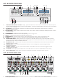
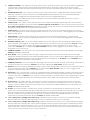
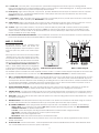
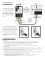
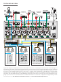
QUICK START GUIDE
MZC-88
Multi-Zone Audio/Video Amplifier Controller
ABOUT MZC-88 QUICK START GUIDE
MZC-88 QUICK START GUIDE is intended to provide top-level instructions for Installation, Configuration and
Connection of a SpeakerCraft MZC-88 System. MZC-88 Quick Start focuses on a MZC-88 ‘default’ system,
that is, a basic eight zone system that includes up to eight audio/video sources, (including the two internal
AM/FM Tuners) that matches the MZC-88 default project included in the EZ-Tools download. This Quick Start
Guide can also be used for getting more sophisticated systems started, but when planning and installing expanded systems with multiple controllers, external amplifiers, multi-room zones or when changing the layout
of the keypad buttons, it is highly recommended that the MZC-88 Hardware Installation Instructions be used
for reference and guidance. Additionally, the Hardware Installation Instructions provide much greater detail
in regard to instructions given here. MZC-88 Hardware Installation Instructions are available as a download
from www.speakercraft.com.
Once a MZC system has been installed, though capable of some basic functions out of the box such as
ON/OFF, Source Selection and Volume/Mute, configuration of MZC-88 advanced features requires SpeakerCraft EZ-Tools Programming Software. EZ-Tools and the EZ-Tools MZC Programming Instructions can be downloaded from: www.speakercraft.com.
MZC-88 FEATURES-FRONT PANEL
1
16
1. 2, 9.
3, 10.
4, 11.
5, 12.
6, 13.
7, 14.
8, 15.
16. 17. 18.
19.
20.
21.
2
3
4
5
6
7
8
9
10 11 13
12
14
17
18
19
15
20
21
ZONE STATUS LED Indicators and Labels – Eight, green LEDs indicate the zones that are currently active. Indented spaces
accept adhesive backed labels for zone/room identification. A sheet of descriptive labels, typical of room or area names
used in homes, is included.
RDS BUTTONS – Enables/disables Tuner Radio Data System information. RDS displays station frequency, call letters,
broadcast genre and time.
MN/ST BUTTONS – Toggles Tuner FM stereo/mono modes. Mono can be useful for cleaning up background noise on hard
to tune channels.
AM/FM BUTTONS – Toggles Tuner AM and FM bands.
ZONE BUTTONS – Selects Tuner Zone for programming and selecting Presets.
TUN +/- – Changes Tuner frequency UP/DOWN when pressed.
TUNER DISPLAYS – LCDs show Tuner status by: Zone, Band, Frequency, Preset, Mode and Frequency Lock.
PRESETS – Tuner Presets 1-10. Press to select preset for programming or channel preset select by zone.
MASTER POWER SWITCH – When pressed to the in position, the MZC-88 is placed in the power ON standby condition,
permitting individual zones to be turned ON and OFF by keypad, or touch panel commands. In the OFF (out) position,
power from the AC mains is completely turned off.
RED INDICATOR LED – Indicates when the Master Power Switch is in the depressed position and that power has been
applied from the AC mains.
CONTROL PORT – One, 4 circuit 3.5mm mini jack connects to a PC running EZ-Tools for system programming and Firmware upgrades.
FIRMWARE UPGRADE – One, two position switch enables the MZC-88 Control Port for Firmware Upgrades instead
of normal system program.
IR CAPTURE – IR learning eye used with EZ-Tools to learn IR Codes not found in the embedded IR Code Library.
ACTIVITY INDICATOR – Flashes when the system is learning IR commands or executing system functions.
MZC-88 FEATURES-REAR PANEL
1
2
3
4
5
6
7
8
9
10
11
12
13
FUSE: T6.3AL 250V
15
14 16
17
19
18
20
21 22
23
1. 8-ZONE KEYPAD INPUTS – One, SCSI terminal connects to a SpeakerCraft KCM-1.0 EZ-Connect Keypad Module for connection
of zone keypads and IR sensors.
2
2.
CONTACT CLOSURES – Two, single pole dry relay contacts used to activate any device that can be controlled or triggered by
a switch closure. These closures can be programmed within EZ-Tools for Momentary, Toggle and Open/Close Paired
operation. Spring loaded terminals accept wire sizes from 24 to 14 AWG. Internal relay contacts are rated at 2A/30V AC or
DC.
3. EXPANSION PORT/LOOP – Two, RJ45 jacks primarily used for looping system data to multiple MZC-88’s in expanded systems.
These jacks can also be used for connection of specialized RS485 controlled products such as the SpeakerCraft MODE
Adapter/Base for adding iPods and SpeakerCraft RSA-1.0(s) for control of multiple RS232 devices.
4. RS232 DATA I/O – One, DB9F terminal allows the MZC-88 to control certain RS232 compatible devices such as source
components and lighting systems.
5.
CONTROL PORT – One, 3.5mm 4-circuit mini jack used for all Controller and Keypad programming. It also accommodates
factory firmware upgrades in conjunction with the Firmware Upgrade On/Off Switch, located on the front panel, item 19. See:
EZ-Tools MZC Programming Instructions for additional information. This por also serves as a bi-directional RS-232 serial interface
allowing the MZC-88 system to be controlled by external devices.
6. PHONE PAGE IN – One, RCA jack provides input for line level audio from sources such as telephone systems, door mics or
other audio paging devices. This jack is programmable in EZ-Tools, to turn on as an ‘Event’, when triggered by the DOORBELL/
STATUS IN Jacks, item 8.
7. VIDEO PAGE IN – One RCA jack provides input for composite video from doorbell paging systems, cameras or other
composite video sources. This jack is programmable in EZ-Tools, to turn on as an ‘Event’, when triggered by the DOORBELL/
STATUS IN Jacks, item 8.
8.
DOORBELL/STATUS IN 1 & 2 – Two, 3.5mm mini jack trigger inputs work in conjunction with the PHONE and VIDEO PAGE IN
jacks, items 3&4. When triggered, the Page Inputs can be turned on in selected zones as programmed in EZ-Tools. If Paging
is not required, these jacks can also be programmed as STATUS INPUTS for power management of Source or Zone
components. POLARITY: TIP= +V; SLEEVE=GND. INPUT VOLTAGE: 3-30V AC or DC to trigger the ON condition. Voltage must
drop below 1V AC or DC for OFF.
9. COMMON IR OUTPUT – One, 3.5mm mini jack outputs all IR commands from IR sensors and Keypads regardless of zone origin.
POLARITY: TIP=SIGNAL; SLEEVE=GND.
10.
HI/LO SWITCH – One, two position switch, sets high or low IR power output to the Common IR Output jack. Set to the LO
setting when driving standard low power emitters (SpeakerCraft IRE-1.0, 2.0, 3.0 and 4.0). Set to HI when driving a high power
emitter (SpeakerCraft IRE-5.0 Blaster) for teaching IR commands into learning remotes. HI OUTPUT: 110mA; LO OUTPUT: 13mA.
CAUTION: The HI position will smoke low power emitters!
11. COMMON STATUS OUT – One, 3.5mm mini jack will go high (+12V DC) when any zone is turned ON and will go LOW (under 1V
DC) when the last zone is turned OFF. POLARITY: TIP=+12V DC; SLEEVE=GND. MAX OUTPUT: 100 mA at 9.5V DC.
12. STATUS IN – Six, 3.5mm mini jack trigger inputs primarily used for power management of common source components that do
not have discreet IR ON/OFF codes. POLARITY: TIP=+V; SLEEVE=GND. INPUT VOLTAGE: 3-30V AC or DC to trigger the ON
condition. Voltage must drop below 1V AC or DC for OFF.
13.
FM/AM/75Ω – One, F-type terminal, connects to a SpeakerCraft HED-1.0 Masthead Amplifier. The HED-1.0 should be located
away from the system components to reduce RF interference and improve reception. FM Dipole and AM Loop antennas
connect to the HED-1.0. CAUTION: Do not connect an antenna directly to this terminal. There is DC voltage present to power
the HED-1.0. This voltage will interfere with antenna performance and possibly cause electrical short if not terminated
properly.
14.
IR OUT (Source) – Six, 3.5mm mini jacks, one per Source, output IR commands to external common source components.
When a source is selected, from a keypad or remote control, IR commands are routed directly to that source. This allows
selective control of multiple same-brand, same-model source components (multiple Satellite Receivers, DVD Players etc).
POLARITY: TIP=SIGNAL; SLEEVE=GND.
15.
IR LOOP – Six, 3.5mm mini jacks, one per Source, provide connections for an IR signal path for external common source
components, when using multiple MZC-88’s in expanded systems. i.e. If using two MZC-88s, the SOURCE IR OUTS on the MZC
Slave unit would connect to the appropriate SOURCE IR LOOPS on the MZC Master unit to pass Source IR commands
between controllers from expanded zones. The IR OUTS on the Master connect to IR EMITTERS attached to the source
components for source IR control from all zones. POLARITY: TIP=SIGNAL; SLEEVE=GND.
16. L, R & V INPUT (Source Left/Right Audio/Video Input) – Eighteen RCA jacks, three for each Source, provide left and right
line-level audio and composite video signal inputs for up to six external common source components.
17.
L, R & V LOOP (Source Left/Right Audio/Video Loop) – Eighteen, RCA jacks, three per Source, provide buffered left and right
line-level audio and composite video outputs that are typically used to loop Source Audio signals to additional zone inputs
on Slave MZC-88’s in expanded systems. i.e. The L, R, V LOOP on the MZC Master would connect to the appropriate L, R, V
INPUT on MZC Slave 1. Slave 1 would then loop to Slave 2, etc. These outputs can also be used to drive local components,
such as a local surround receiver, when not used for expansion.
3
18.
19.
L & R PRE-OUT – Two, RCA jacks, one pair per Zone, provide left and right line-level audio outputs for driving external
high-power/audiophile two-channel amplifiers in large or outdoor zones or a critical listening zone, or driving a multi-channel
amplifier for additional rooms, (sub-zone expansion) where needed.
IR OUT (Zone) – Eight, 3.5mm mini jacks, one per zone, provides dedicated Zone IR output for exclusive control of a specific
zone component. (i.e., a dedicated satellite receiver or DVD player, that cannot be controlled from any other zones).
POLARITY: TIP=SIGNAL; SLEEVE=GND.
20. L & R SPEAKERS – Eight, removable screw-down connectors, one terminal per zone, provide quick connection of the internal
amplifiers to Zone stereo speaker pairs. WIRE GAUGE: 14 to 24 AWG.
21. VIDEO OUTPUT – Eight, F-type terminals, one per zone, provide a dedicated composite video output for each zone. 75 ohm
outputs provide matched line impedance for high quality video over RG6 cable for lengths up to 500 feet.
22.
VC/NVC – Eight, two-position switches, one per zone, switch the PRE-OUT jacks to VC - internal Volume Control (variable,
zone volume controlled by keypads or IR remote) or NVC - No Volume Control (fixed, zone volume controlled by in-wall
volume control or volume control on an external device such as an A/V Receiver). In either case, the tone control action
remains available for room “EQ” settings.
23. IEC TYPE AC MAINS RECEPTACLE AND FUSE – One, Standard IEC 3-conductor AC line cord receptacle, connects to included AC
power cord. Also houses the rear panel replaceable AC mains fuse (T6.3AL 250V).
SAT
DVD
SAT
CBL
AUX
CBL
AUX
3456
01
EF 2
DVD
4
5
ADDRESS
CD
KEYPAD EXPANSION
TNR2
iPOD1
-RELAY
TNR1
CD
+RELAY
TNR2
CD
AB
TNR1
iPOD1
3
789
The MZC-88 System can be controlled using
SpeakerCraft EZ-Pads, IMKPs and MODE 3.1s.
Keypad configurations vary from system to system
and some parts may need to be ordered separately.
2
1
MKP-1.1 FEATURES
MKP-1.1
J-Box EZ-Pad w/IRC
-Master-
SpeakerCraft
1.
485 B
GND
485 A
IR I/O
+12V
Each keypad comes with a set of factory installed
8
6
“default buttons” plus a good variety of loose butMUTE
MUTE
PWR
tons packed with them. The default buttons can
PWR
be easily changed to meet the needs of the installation. For more information on changing keycaps,
4
7
see: MZC-88 Hardware Installation Instructions. The
Rear View
MKP-1.1 shown reflects the Source configuration
MKP-1.1
of the EZ-Tools MZC-88 Default Project. A Function
MKP-1.1 Master Keypad
With Trim Plate (Not Included)
Module (FKP-1.0) and Numeric Module (NKP-1.0)
are available options for additional control capability, however, a MKP-1.1 or MKP1.0 Master Keypad is required for each zone. NKP1.0s and FKP-1.0s will not function on their own. See: MZC-88 Hardware Installation Instructions for additional information.
MKP-1.1 SOURCE/FUNCTION BUTTONS – When used with MZC-88, six of this set of eight buttons may be programmed as source
or function buttons. The top two source buttons are dedicated to Tuner 1 and Tuner 2 when used with a MZC-88. Any mix of
source/function buttons is allowed on the remaining six, including all source or all function buttons, if desired. All buttons have
an optional green backlight, configurable in EZ-Tools. Default timeout is 60 sec. When a Source Button is pressed, it turns a
low-level red color to show that it is the active source and the system is ON.
2. KEYPAD EXPANSION TERMINAL – This 16-pin header terminal is used to inter-connect the NKP-1.0 and FKP-1.0 modules for
expansion as needed. A ribbon cable is packed with each NKP-1.0 and FKP-1.0 for making these connections.
3. ADDRESS SWITCH – An unique hex address must be set for each master keypad when connected on a common bus within a
single zone. Unique addresses are not required zone-to-zone. (One keypad per zone.) It provides up to 16 addresses (0 to F).
4. SNAP TABS – These tabs hold the decorator style insert panel to the metal mounting plate and are easily released for custom
changing of the buttons.
5. MOUNTING PLATE – Standard plate allows the keypad module to be attached to standard in-wall J-Boxes using the 2 screws
provided. Allows attachment of standard decorator type cover plates (also screw-less snap-on plates).
6. EZ-CONNECT TERMINALS – These spring-loaded terminals accept wire sizes 14 to 28 AWG for connection of the following:
+Relay/–Relay – For connection of an optional EPR-1.0 EZ-Pad Relay Speaker Muting Module. See: MZC-88 Hardware
Installation Instructions for additional information.
+12V DC – Powers the Keypad, including the internal IR Receiver. Includes reverse voltage protection.
IR/IO (Data) – Sends IR control signals for control of system components.
GND – Return for Power, IR signal and Data
485 A/485 B – Balanced, bi-directional system communications data.
7. FUNCTION BUTTONS – These lower 4 buttons (5 buttons in the case of the MKP-1.0) can be programmed for any function
except source select.
8. IR RECEIVER LENS – EZ-Pad version MKP-1.1 includes SpeakerCraft’s exclusive ANS IR Receiver, built-in. The IR Receiver allows
use of a handheld remote for control of system components.
4
KEYPAD CONNECTIONS
KCM-1.0
485 B
485 A
GND
IR I/O
Rear View
Brown
Orange Pair
Blue Pair
Green Pair
Brown-White
Brown
+12V
IR IN
GND
EZ PAD
ZONE 2
Brown-White
485 A
485 B
+12V
EZ PAD
ZONE 1
IR IN
GND
SpeakerCraft
485 A
MKP-1.1
485 B
01
EF 2
CAUTION:
Choice of colors used
is not important.
However, colors MUST
match to terminations
at each end as shown!
(see text)
J-Box EZ-Pad w/IRC
-Master-
+12V
-RELAY
CD
AB
+RELAY
789
CAT-5 WITHOUT RJ45 CONNECTORS
– Connect EZ-Pads to KCM-1.0 as
shown. Be sure to maintain consistent
color code when making connections. For IMKP, use same pin-out. See:
MODE 3.1 Installation Instructions for
plug-in connector and RJ45 pin-outs.
Maximum recommended lead length
with CAT-5 cable is 1000' (305m).
(MODE, 500’)
KEYPAD EXPANSION
3456
ADDRESS
Zone Input
Orange Pair
Blue Pair
Green Pair
Inter-room
Twisted Pair
Cat. 5 Cable
1000’(305m) Max.
Use Twisted Pair
for 485A & 485B
CAT-5 WITH RJ45 CONNECTORS (EZ-Pad Only)
– When using RJ45 connectors, connect the
CAT-5 cable to the keypads using SpeakerCraft
model RJA-1.1 RJ45-TO-WIRE PIN ADAPTERS.
Insert the RJA-1.1 pins into the keypad’s EZConnect Terminals and snap the levers in
place. Be sure RJA-1.1 pin orientation is correct
prior to powering up the system. Repeat at
KCM-1.0 end using RJA-1.1s to adapt Zone termials to RJ45 connections. CAT-5 cable should
be configured in a pass-through (pin to pin)
termination.
MZC-88 INTERNAL TUNER SETUP
Connnections
1.
2.
3.
4.
Connect the FM/AM/75Ω to HED AMP Terminal on the MZC-88 to the ‘To Receiver’ Terminal on the HED-1.0. Use RG6
quad-shield coaxial cable up to 100’ in length, terminated with male F-type connectors. Refer to System Diagram
Connect included AM Loop antenna to the G and AM spring clip terminals on the HED-1.0. (Polarity non-critical.)
If using the included indoor FM Dipole antenna, connect the spade ends to the included balun.
Connect the balun and FM Dipole antenna assembly to the FM F-type terminal on the HED-1.0.
See: MZC-88 Hardware Installation Instructions for important notes regarding HED-1.0 and antenna connections.
Preset Programming
The MZC-88 has two built-in AM/FM Tuners that allow programming of up to 10 AM or FM Stations per Tuner per Zone. Each Zone’s
presets require programming by Tuner and by preset. Tuner Presets can only be programmed from the MZC-88 Front Panel controls.
Programming the keypads for control of the tuners must be done in EZ-Tools.
1. Repeatedly press the ZONE button to select the zone’s presets to be programmed. Zone will appear on the tuner display.
2. Press the AM/FM button to select AM or FM. The tuner display will indicate the band selected.
3. Press the TUN+/- buttons to tune the station to be programmed. Left and right arrow icons will appear in the tuner display when
a station is not properly tuned. A solid bar will appear when the station is properly tuned.
4. If a FM station is noisy, press the MN/ST (mono/stereo) button to force mono reception.
5. Press and hold the Preset Button that the currently tuned station is to be programmed to for three seconds.
6. Repeat steps 1-5 for all presets for all zones for Tuners 1 and 2.
See: MZC-88 Hardware Installation Instructions for a complete explanation of Tuner programming.
5
TYPICAL MZC-88 SYSTEM
IPod
FM Antenna
AM Loop
Antenna
MODE
BASE
CD
SpeakerCraft IRE Series
IR Emitter
From MZC-88 Source IR Out
1
Stereo Line Level Audio/
Composite Video
From Source Out
To MZC-88 Source In
MODE JUKEBOX
14AWG
PS-1.0 200mA
Power Supply
CABLE
HED-1.0
24V DC
iPod Base
Aux. Input
DVD
Expansion
Line Out
MODE
ADAPTER
SATELLITE
RS232
DATA I/O
12VDC
RSA-1.0
RS232 Interface Adapter
BCD
5
234 6
789A
SpeakerCraft
E F 01
ADDRESS
SpeakerCraft
PS-3.0 24VDC
Power Supply
®
PROGRAMMING
OFF
Earth
Ground
(See Text)
ON
HI
LO
IR
IR
IN
EXPANSION
PORT
LOOP
CONTROL
PORT
RSA-1.0
RG6 Coax
FUSE: T6.3AL 250V
RG6 Coaxial Cable
18-14AWG 2-Conductor Stranded Speaker Wire
CAT5 Cable
KCM-1.0
SpeakerCraft AIM5 Three
Zone Speakers
Zone
Video
Display
SpeakerCraft AIM5 Three
Zone Speakers
TNR1
TNR2
TNR1
TNR2
iPOD1
CD
iPOD1
CD
DVD
SAT
CBL
AUX
SpeakerCraft AIM5 Three
Zone Speakers
1
2
3
TNR1
TNR2
4
5
6
iPOD1
CD
7
8
9
TRK
0
DSC
Zone
Video
Display
DVD
SAT
CBL
AUX
1
2
3
4
5
6
7
8
9
TRK
0
DSC
GUIDE
SpeakerCraft AIM5 Three
Zone Speakers
MENU
SEL
ESC
INFO
MENU
SEL
MUTE
PWR
MKP-1.1
Trim Plate Not Included With Keypad
ZONE 1
MUTE
RDM
MUTE
RDM
PWR
GRP
PWR
GRP
PLAY
B
T
MKP-1.0 NKP-1.0
MKP-1.1 NKP-1.0 FKP-1.0
Trim Plate Not Included With Keypad
Bezel Included With MODE 3.1
ZONE 2
ZONE 3
ZONE 4
Trim Plate Not Included With Keypad
MODE 3.1
Typical MZC-88 System showing Keypad, Source and Speaker connections. A MZC-88 System will have limited functionality right out
of the box such as ON/OFF, Source Select and Volume/Mute. Common source control and power management must be configured
in EZ-Tools. High power or multi-channel amplifiers can be added to the individual zones for high audio output in large rooms or outdoor zones or when adding additional rooms or “sub-zones” to a default system. Additionally, the MZC-88 has two programmable
contact closures for control of lifts, screens, drapes etc. and an RS232 port for control of compatible components or whole-house
sub-systems. The MZC-88 also features two Doorbell/Status inputs that can be used for common source power management or tiggering a system ‘event’ from a doorbell module. For additional information on connection, configuration and programming of these
optional features see: MZC-88 Hardware Installation Instructions and EZ-Tools MZC Programming Instructions.
6
MZC-88 SYSTEM INSTALLATION AND CONNECTIONS
INSTALLATION-HEAD END
The MZC-88 and external source components will typically be installed at the System Head-End. They can be mounted on shelves
in a wall unit, entertainment center or closet, or rack mounted in a standard 19” rack mount system. Source components such as
DVD/CD players and VCR’s should be installed so the user has easy access for loading discs and tapes.
Though heavy, the MZC-88 should be mounted at the top of the equipment rack so heat generated by the controller will not affect
the other system components. Always leave adequate space between system and source components for airflow. Failure to do so
can cause damage to the components from overheating. Never block the vent holes on the top or bottom of the MZC-88. Blocking
the vent holes will cause the controller to overheat. For additional information on MZC-88 systems using multiple controllers or external amplifiers, see: MZC-88 Hardware Installation Instructions.
CONNECTIONS-HEAD END
KCM-1.0
1. Using the included SCSI Cable, connect the KCM-1.0 to the MZC-88 as shown in the Typical MZC-88 System Illustration.
Keypads
1. Connect each keypad run to the appropriate Zone on the KCM-1.0. Be sure CAT-5 cable and RJ45 connectors (if used) are
properly configured. IMKP uses the same pin-out as EZ-Pad. See: MODE 3.1 Installation Instructions for pin-out.
External Source Components
1. Connect the L & R line-level audio and composite video OUT of each external source component to the appropriate L & R linelevel audio and composite video SOURCE IN on the MZC-88 Rear Panel. Use quality RCA-RCA stereo A/V cables terminated with
gold connectors.
Emitters (Source)
1. Carefully attach a SpeakerCraft IR Emitter (Models: 1.0, 2.0, 3.0, 4.0) over the IR eye on the front panel of each external source
component to be controlled via infrared.
2. Carefully pull the emitter wire to the rear panel of the MZC-88. Do not block accesses for discs and tapes. Do not pinch emitter
wires between components.
3. Connect the 3.5mm mini plug to the appropriate Source IR OUT.
Speakers
1. Connect each Zone speaker run to the appropriate Zone SPEAKER terminal using the included removable screw down connectors.
2. Strip approximately 1⁄4 inch of each lead and twist the stripped ends so there are no loose strands that can cause shorts.
3. Carefully slide the individual conductors into the appropriate L+,L-/R-,R+ speaker terminals on the removable screw down connector. Visually check for loose ends. Lightly pull the wire to confirm connection.
5. Plug connector into the appropriate Zone SPEAKER Terminal.
INSTALLATION-ZONES
Keypads should typically be located near a door or entry point to a room. Avoid mounting keypads, IR receivers, volume controls
or any other control devices in areas of high moisture such as sinks, showers, bathtubs etc. Care should be taken to avoid mounting Keypads and IR receivers in locations subject to direct sunlight. Sunlight can interfere with system operation and, in time, cause
deterioration to the keypad and trim plate materials.
WARNING: Never mount a keypad, IR receiver or volume control in the same J-box as high voltage devices. This can affect
system performance and is a violation of Electrical Code in some areas. (Be aware of local Electrical and Building Codes. These
codes can affect the type of J-boxes permitted, mandate wire specifications and regulate other aspects of the installation that
may not pass inspection if necessary.)
CONNECTIONS-ZONES
Keypads
1. Connect each Keypad cable run to the appropriate Zone Keypad. When not using RJ45 connectors, be sure to maintain
consistent color code when making connections . When using RJ45 connectors, be sure the RJA-1.1 adaptor pins are oriented
properly (EZ-Pad). Refer to: MZC-88 Quick Start Guide/Keypad Connections.
2. Install each Keypad into a proper low-voltage J-box and finish with an appropriate trim plate (Not included with EZ-Pad).
Speakers
1. Connect ZONE SPEAKERS L+,L-/R-,R+ OUTPUTS from the MZC-88, to the appropriate Zone Speaker pair.
2. Strip approximately 1⁄4 inch of each lead and twist the stripped ends so there are no loose strands that can cause shorts.
3. Connect as appropriate to the L+,L-/R-,R+ terminals on each speaker.
4. Visually check for loose ends. Lightly pull the wire to confirm connection.
5. Install speakers into dry-wall cut-outs or SpeakerCraft InstaLLock™ New Construction Brackets (if used) as appropriate.
Video Displays
1. Connect each Zone Video Output to the appropriate Zone Video Display.
7
MZC-88 SPECIFICATIONS
AUDIO SECTIONS
Rated Power/Channel (RMS, 2 channels driven into 8 Ohms)
AM TUNER SECTIONS
50 Watts, 20 Hz to 20 kHz
THD (at rated power) < 0.5 %
Power/Channel (RMS, 2 channels driven into 4 Ohms)
70 Watts @ 1 kHz
Input Sensitivity (For rated power @ max VC) 300 mV, VC
2.8 V, NVC
Input Impedance (Source Inputs) 1.7 V, VC
810 mV, NVC
Output Impedance (Pre-outs) < 300 Ohms
20 Hz to 20 kHz +/- 1.5dB
> 50 dB @ 10 kHz
Crosstalk Between Sources > 65 dB @ 10 kHz
> 95 dB (VC 20 dB below FCW)
Bass Control Range +/- 10 dB @ 100 Hz
Treble Control Range +/- 10 dB @ 10 kHz
Bandwidth (Outputs 75 Ohms Terminated)
10Hz to 6MHz +/- 1dB
Input/Output Levels (Outputs 75 Ohms Terminated)
1.0V p-p +/- 5%
S/N Ratio (65 dBf, 98.1 MHz)
Freq. Response (Mono or Stereo)
Separation (@ 1 kHz, 65 dBf)
THD (1 kHz, 65 dBf, 98.1 MHz)
Capture Ratio (45 dBf)
Alternate Channel Selectivity
S/N Ratio (400kHz, 10mV/m Input @ 1000kHz, 30% Mod.)
THD (400 Hz, 10mV/m Input
@ 100kHz, 30% Mod.)
46dB
Image Rejection (1400kHz)
38dB
0.7%
CONTROL SECTIONS
Contact Closures (dry) Phone Page In Voltage/Impedance
Doorbell In 1 & 2, 3V to 30V AC or DC
Common IR Out – HI (High Power)
– LO (Emitter power) Zone IR Outs – Voltage/Impedance
Common Status Out (0 to 12 VDC)
Status In (3-8)
4.5 to 30 V DC
FM TUNER SECTIONS
Sensitivity (50dB quieting, 98.1 MHz)
30dB
Source IR Outs (and loop) – voltage/impedance
VIDEO SECTIONS
Usable Sensitivity (IHF, 98.1 MHz)
750 µV/m
Selectivity (@ S/N 20dB, +/- 10kHz)
Video Page In
Channel Separation Tuning Range
Sensitivity (20dB Quieting, 1000kHz loop antenna)
2.5 V
Output Voltage @ Pre-Outs (w/300 mV @ source inputs) S/N Ratio (Re: Rated output, IEC A, source inputs shorted)
520 to 1710 kHz
> 22 K Ohms
Input Overload (Source Inputs) Frequency Response (1 Watt @ 8 Ohms)
Tuning Range
87.5 to 108.0 MHz
Status In-Video
(Video Source Inputs 3-5)
2A, 30 VAC/DC max
Audio Line Level, > 22k Ohm
1.0V p-p 75 Ohm
10 mA @ 12 VDC/AC
9V Active High, 82 Ohms,
(110 mA Peak)
9V Active High, 670 Ohms,
(13 mA Peak)
9.2V Active High, 620 Ohms, (13 mA Peak)
11.5 V Active High, 390 Ohms ( 29 mA Peak)
9.5 V @ 100 mA
2mA @ 12V
1V Video p-p (0.5 V p-p min)
12dBf Mono
18dBf Mono, 45 dBf Stereo
75 dB Mono, 65 dB Stereo
30 Hz to 15kHz +/- 3dB
> 40 dB
0.15% Mono, 0.2% Stereo
2.0 dB
65dB
GENERAL
Power Consumption
No Signal (idle)
75 Watts
At 1/8 Rated Power (6.25 Watts/Channel)
275 Watts
Line Ratings (N.A. Version) Rear Panel Fuse Dimensions Weight 120 VAC, 3.0A
T6.3AL 250V
17” (432mm) W x *5-1⁄4”
(133mm) H x 14-3⁄4” (375mm) D
*5-3⁄4” (146mm) H, including feet.
31.5 lbs (14.3 kg)
940 Columbia Ave., Riverside CA 92507 | USA (800) 448 0976 Fax (951) 787 8747 International +1 951 787 0543 | www.speakercraft.com
LIT13188