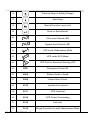
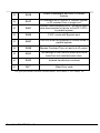
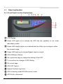
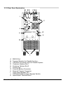
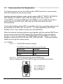
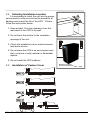
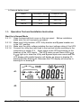
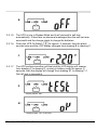
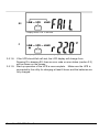
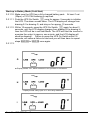
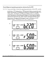
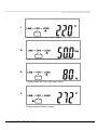
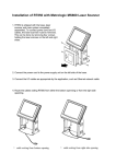
1
UniStar P Series 6kVA, 8kVA & 10kVA Tower Models SC60021T, SC60022T SC80021T, SC80022T SC11021T, SC11022T Parallel Redundancy/Capacity On-Line UPS User’s Manual 301 Gaddis Boulevard • Dayton, Ohio 45403 U.S. Toll Free 866-261-1191 (937) 253-1191 • Fax: (937) 253-1723 Web site: www.stacoenergy.com 003-2282 Rev G 12/11/2009 Table of Contents 1. 2. 3. 4. 5. 6. 7. 8. Important Safety Instruction ............................................................................. 2 1.1. An Important Notice ......................................................................................... 2 1.2. Storage Instruction ............................................................................................ 4 Product Introduction ......................................................................................... 5 2.1. General Characteristics ..................................................................................... 5 2.2. Symbols on the LCD Display Panel ................................................................. 7 2.3. Panel explanation ............................................................................................ 10 2.4. Communication Port Explanation ................................................................... 13 Installation and Operation ............................................................................... 14 3.1. Unpacking ....................................................................................................... 14 3.2. Selecting Installation Location........................................................................ 15 3.3. Installation of Casters Cover ........................................................................... 15 3.4. Terminal Block Explanation ........................................................................... 16 3.5. Operation Test and Installation Instruction ..................................................... 19 Troubleshooting Guide ................................................................................... 32 4.1. Trouble Shooting ............................................................................................ 32 Bundled Software Installation Guide .............................................................. 34 5.1. Hardware Installation ...................................................................................... 34 5.2. Software Installation ....................................................................................... 34 Customer Options Slots .................................................................................. 35 6.1. All the below interface cards are with built-in EPO function ......................... 35 6.2. R2E(2nd RS-232 ) card ................................................................................... 35 6.3. RSE(RS-485) card .......................................................................................... 35 6.4. USE(USB) card............................................................................................... 36 6.5. DCE(Dry Contact)-B card .............................................................................. 36 6.6. SNMP Cards ................................................................................................... 37 6.7. The Installation of Interface Cards.................................................................. 38 Hot Swappable Battery Replacement ............................................................. 39 Specifications .................................................................................................. 41 Form No. 003-2282 Rev G 1 1. Important Safety Instruction 1.1. An Important Notice 1.1.1 For Parallel System installation, please refer to Parallel System Installation Guide Part number 003-2302 1.1.2 Because of “small leakage currents” generated by the EMI filter of the UPS, it is necessary to insure that the UPS is properly grounded before connecting AC power to the input. 1.1.3 To ensure safety in all applications where a UPS is hard wired to the Electrical Supply, ensure that the system is installed by a Qualified Electrical Contractor. 1.1.4 The UPS has its own internal energy source (battery). When the UPS is operating from battery power when no AC input is available, there will be voltage at the output terminals. 1.1.5 Make sure that the AC Utility power source is correctly grounded. 1.1.6 Do not open the case, as there are no serviceable parts inside. Your Warranty will be void. 1.1.7 Do not try to repair the unit yourself; contact your local supplier or your warranty will be void. 1.1.8 Make sure that the rated input voltage of the UPS matches the available AC mains voltage. 1.1.9 Use a certified input power cable with the correct plugs and sockets for the appropriate voltage system. 1.1.10 To eliminate any overheating of the UPS, keep all ventilation openings free from obstruction, and do not store anything on top of the UPS. Keep the UPS 12 inches away from the wall. 1.1.11 Make sure the UPS is installed within the proper environment as specified. (0-40℃ and 30-90% non-condensing humidity) Form No. 003-2282 Rev G 2 1.1.12 Do not install the UPS in direct sunlight. if the batteries fail. Your warranty may be void 1.1.13 Install the UPS indoors as it is not designed for installation outdoors. 1.1.14 Dusty, corrosive and salty environments can do damage to any UPS. 1.1.15 Install the UPS away from objects that give off excessive heat and areas that are excessively wet. 1.1.16 If liquids are spilled onto the UPS, or foreign objects dropped into the unit, the warranty will be null and void. 1.1.17 The battery will discharge naturally if the system is unused for any length of time. 1.1.18 Recharge the batteries every 2-3 months if unused. If this is not done the warranty will be null and void. When installed and being used, the batteries will be automatically recharged and kept in top condition. 1.1.19 This UPS supports electronic equipment in offices, telecommunications, process control, medical and security applications. This UPS is NOT intended for use in the following application: a. Medical equipment directly related to human life b. Elevator, Metro (Subway) system or any other equipment related to human safety. c. Public system or critical computer systems. 1.1.20 Do not install the UPS in an environment with sparks, smoke or gas. 1.1.21 Make sure the UPS is completely turned off when moving the UPS from one place to another. It might cause electrical shock if the output is not turned off. 1.1.22 The UPS is equipped with a Maintenance Bypass Switch. Please follow the procedures strictly to switch on/off the Maintenance Bypass Switch. Form No. 003-2282 Rev G 3 1.1.23 The UPS offers CVCF (Constant Voltage Constant Frequency) setting function. a. For correct setting and wiring, please contact your local agent. b. Do not attempt to configure the UPS for CVCF by yourself; otherwise your warranty will be void. 1.1.24 This UPS has been designed and constructed to protect your assets from the wide range of power aberrations experienced on Utility power lines today. It is your insurance for reliable, clean and stable voltage supply. It is worth taking care to install the system correctly and to have it maintained correctly by your local dealer. 1.1.25 SAVE THESE INSTRUCTIONS - This Manual Contains Important Instructions that should be Followed during Installation and Maintenance of the UPS and Batteries. 1.1.26 Intended for Installation in a Controlled Environment. 1.1.27 CAUTION – 6Kva - A load disconnect switch shall be provided by others for the AC output circuit. To reduce the risk of fire, connect only to a circuit provided with branch circuit over-current protection for 30 amperes rating in accordance with the National Electric Code, ANSI/NFPA 70. 1.1.28 CAUTION – 8/10Kva - To reduce the risk of fire, connect only to a circuit provided with branch circuit over-current protection for 40 amperes rating in accordance with the National Electric Code, ANSI/NFPA 70. 1.1.29 Use No. 10 AWG, 60C copper wire and 22.1 lb-in Torque force when connecting to terminal block. 1.2. Storage Instruction For extended storage through moderate climate, the batteries should be charged for 12 hours every 3 months by connecting the UPS input to an appropriate power source and start the UPS according to the instructions in this manual. Repeat this procedure every 2 months under high temperature environment. Form No. 003-2282 Rev G 4 2. Product Introduction 2.1. General Characteristics 2.1.1 True online architecture continuously supplies in your critical device with a stable, regulated, transient-free pure sine wave AC Power. 2.1.2 20KHz PWM sine-wave topology yields an excellent overall performance. High crest factor capability of the inverter handles all highinrush current loads without a need to upgrade the power rating. 2.1.3 Multi-functional LCD/LED panel displays various conditions of the UPS. The LED display shows the UPS working status, Utility Status and UPS Abnormal status. The LCD display shows Input and Output Voltage, Frequency, Load Status, Inner cabinet temperature, and Abnormal conditions. 2.1.4 To protect the unit from overload, it automatically switches to bypass mode in 160 seconds~ 40ms if loading is between 105%~ 150% of rating. At 150% of rating, it switches to bypass mode immediately. The UPS will automatically switch the load back to inverter mode once the overload condition ceases. 2.1.5 If a short circuit is connected to the output the UPS will shut off the output voltage instantly. The output voltage will remain off until the short circuit is removed from the output. 2.1.6 Should the unit become overheated, the internal thermal Switch will detect the heat and switch to bypass mode. When the unit is cooled it will switch the load back to inverter automatically. 2.1.7 Fully digitalized control circuits built into the UPS enhance functionality while providing a high-level of protection of the UPS. Powerful Communication capability enhances its capability for remote control and monitoring. 2.1.8 Maintenance-free sealed-type battery minimizes after-sales service. 2.1.9 Built in maintenance bypass switch provides an easy and safe troubleshooting or maintenance function when the Utility is normal. Form No. 003-2282 Rev G 5 2.1.10 Providing four different working modes, such as Normal, ECO, CF50 and CF60, it may widely be used in a variety of applications. 2.1.11 DC-start function allows the UPS to be started during power outages. 2.1.12 Revolutionary battery management circuit analyzes battery discharging status to adjust battery cut-off point and extend the life of batteries. 2.1.13 Intelligent temperature-controlled fan extends the life of the fan and reduces noise. 2.1.14 Built in diagnostics use fault codes, displayed on the LCD, to assist in finding the cause of a problem with the unit. 2.1.15 In case the UPS is out of order, Fault status will be shown on the LCD screen. 2.1.16 When the UPS is operated as a frequency converter under CF50 or CF60 mode, the recommended load connected shall be 75% of rated capacity if the input voltage is between 176~280Vac and 50% of the rated capacity if the input voltage is 160~280Vac. Form No. 003-2282 Rev G 6 2.2. Symbols on the LCD Display Panel Item Symbol Description 1 LINE Utility or Bypass Source 2 Battery Low 3 Battery Abnormal 4 UPS Overloading 5 UPS Working in specified mode* 6 A Blackout Transfer occurred in UPS Output 7 Bypass Input Abnormal, UPS fails to transfer to bypass, Bypass Abnormal at ECO mode 8 Utility Input Abnormal 9 10 OFF LINE OFF UPS Shutoff UPS Abnormal Lock 11 UPS Flow Chart 12 4 Digits Measurement Display 13 Indicate the item desired to be measured 14 UPS ON Switch or Alarm Silence 15 UPS OFF Switch Form No. 003-2282 Rev G 7 16 Previous Page or Setting Change 17 Next Page 18 Special Function Log in /out 19 Enter or Reconfirmed 20 Utility Input Normal LED 21 Bypass Input Normal LED 22 UPS under Redundancy Mode 23 UPS under ECO Mode 24 UPS Fault or Abnormal Warning LED 25 EPO Emergency Power Off 26 Er05 Battery Weak or Dead 27 Er06 Output Short Circuit 28 Er10 Inverter Over-current 29 Er11 UPS Overheat 30 Er12 UPS Output Overloading 31 Er14 Fan error 32 Er15 Wrong Procedure to enter Maintenance Mode Form No. 003-2282 Rev G 8 Output Parameters Set Error in Parallel System 33 Er16 34 Er17 35 Er21 36 Er24 CVCF mode with Bypass input 37 Er27 The UPS must be operated in normal mode in parallel system 38 Er28 Bypass Overload Time out and cut off output. 39 Er31 The settings of both control board and driver board are not matched each other. 40 Er33 Isolated transformer overheat 41 Er** Other Error code ID Numbers are in conflict in Parallel System or ID number Error in single unit Parallel communication error ( communication wire disconnected or failure to find ID1 UPS ) in parallel system The specified modes include Normal mode, ECO mode, CVCF mode, etc.. Form No. 003-2282 Rev G 9 2.3. Panel explanation 2.3.1 Front Panel Function Explanations LCD Display Green LED lights up to indicate the UPS has the capability to run under redundancy mode. Green LED steadily lights up to indicate that the Utility input voltage is within the nominal range. Green LED lights up to indicate Bypass Input is normal. UPS ON/Alarm Silence. Go to previous page or change the setting of the UPS. To re-confirm the change of UPS Setting. Go to next page. UPS OFF Switch. Special functions log in/out . UPS is working under ECO(Economic) mode. UPS Fault or Abnormal . Form No. 003-2282 Rev G 10 2.3.2 Rear Panel Explanation M ED CBA I F J G K H N L A B C D E F G H I J K RS232 Port Terminal Resistor for Parallel function CAN Bus Connection Port for Parallel System Customer Options Slot 1 Customer Options Slot 2 Cooling Fan External Battery Connector External Charger Connector Utility Input Breaker CB1 CAM Switch(Maintenance Bypass Switch) Input/Output Terminal Block Form No. 003-2282 Rev G 11 L Fixing Holes for External Charger Cabinet M EPO (Emergency Power Off) : Short to enable the function N Thermal breaker for protection of load in abnormal conditions: CB3 (8 and 10kVA models only) OUTPUT G2 N22 L22 N21 N22, L22, N21, L23, L21 : UPS OUTPUT G2 : OUTPUT EARTH GROUND Form No. 003-2282 Rev G INPUT L23 L21 G1 N1 L12 L11 L11 : (not connected, used for Dual Input Only) L12-N1 : UTILITY INPUT G1 : INPUT EARTH GROUND 12 2.4. Communication Port Explanation The Communication port on the UPS provides RS232 protocol to communicate with UPS software for remote monitoring. nd Available optional interfaces cards, which contains R2E (2 RS232, SC-RS232), RSE (RS485, SC-RS485), USE (USB, SC-USB), DCE (Dry Contact, SCContact/EPO), as well as SNMP card (SC-SNMP1), can be added according to need. However, the R2E card, RSE card and USE card cannot be used simultaneously. The bundled software of the UPS is compatible with many operating systems such as Windows 98, & 2000, ME, NT and XP. For other applications like Novell, NetWare, Unix, Linux, please contact your local distributor. When the optional interface cards are used together with the onboard RS232 port, during communication the EPO signals (SC-Contact/EPO) will get the highest priority in control command, then the SNMP/WEB card (SC-SNMP-1), then the shutdown command at the DCE card, R2E, RSE and USE. Finally the onboard RS232 port will get the lowest priority. 2.4.1 RS232 2.4.1.1.1. The RS232 interface settings The RS232 interface shall be set as follows: Baud Rate 9600 bps Data Length 8 bits Stop Bit 1 bit Parity None 2.4.1.1.2. The Pin Assignments of true RS232 type The Pin Assignments of true RS232 type are illustrated as follows: 9 8 7 6 Form No. 003-2282 Rev G 5 4 3 2 1 Pin 3: RS232 Rx Pin 2: RS232 Tx Pin 5: Ground 13 3. Installation and Operation The packing material and the external condition of the unit should be inspected carefully before installation. Retain the packing material for future use. 3.1. Unpacking Take the UPS out of the PE foam. Unwrap the UPS. Standard Package includes: 1 set of User's Manual 1 set of UPS communication software with RS232 cable 1 set of Metal Accessories Kit as below: Package for the UPS with Isolation transformer: No. 7 wire to be use for terminal block jumpers (included) X2 Form No. 003-2282 Rev G 14 3.2. Selecting Installation Location It is necessary to install the unit into the proper environment in order to minimize the possibility of damage and extend the life of the UPS. Please follow the instructions below: 1. Keep at least 12 inches clearance from the rear panel of the UPS to the wall. 2. Do not block the air-flow to the ventilation openings of the unit. 0℃ 40℃ 3. Check the installation site to avoid excessive heat and moisture. 4. Do not place the UPS in an environment near dust, corrosive or salty material or flammable objects. 5. Do not install the UPS outdoors. 3.3. Installation of Casters Cover Form No. 003-2282 Rev G Relative humidly (non condensation) 30% ~ 90% 15 3.4. Terminal Block Explanation OUTPUT G2 N22 L22 N21 INPUT L23 L21 N22, L22, N21, L23, L21 : UPS OUTPUT G2 : OUTPUT EARTH GROUND G1 N1 L12 L11 L11 : (not connected, used for Dual Input Only) L12-N1 : UTILITY INPUT G1 : INPUT EARTH GROUND L11: Not Connected; (L11) Used as bypass input on Dual Input Model (DIM) units only. (Models SCxxx21T and SCxxx22T are NOT DIM) L12-N1: Utility Input power when the UPS is running in Utility mode. Also provides bypass on Models SCxxx21T and SCxxx22T. G1: UPS Input Ground. L21、L23、N21、L22、N22: G2: UPS Output Ground. UPS Output. Remarks: Input Connection 1. Connect the utility AC source to UPS from L12-N1 terminal. Output Connection(s) 2. When an Isolation transformer is NOT installed, the UPS output terminals will be L22-N22 (Models SCxxx22T). Output voltages for these models are selectable from 200, 208, 220, 230, and 240Vac. 3. When the Isolation transformer is installed (Models SCxxx21T): Output voltage on the front panel display represents “Inverter” output, which is the input to the isolation transformer, not the UPS output. a. For 120V/120Vac system (2 branches of 120V, each at ½ total rated kVA) L22-N22 120V L21-N21 120V N22 L22 N21 120V Form No. 003-2282 Rev G L23 L21 120V 16 b. For 120Vac system (1 branch of 120V at full rated kVA) Jumper L22-L21 and N22-N21 L22-N22 120V N22 L22 N21 L23 L21 120V c. For 240/120Vac system (2 branches of 120V, 1 branch of 240V) Jumper L22-N21 L22-N22 120V L21-N21 120V L21-N22 240V N22 L22 N21 120V L23 L21 120V 240V d. For 240Vac system (1 branch of 240V at full rated kVA) Jumper L22-N21 L21-N22 240V N22 L22 N21 L23 L21 240V e. For 208V/120Vac system (2 branches of 120V, 1 branch of 208V) Jumper L22-N21 L22-N22 120V L21-N21 120V L23-N22 208V N22 L22 N21 120V L23 L21 120V 208V Form No. 003-2282 Rev G 17 f. For 208Vac system (1 branch of 208V at full rated kVA) Jumper L22-N21 L23-N22 208V N22 L22 N21 L23 L21 208V NOTE: For models with an isolation transformer, the output is configurable to 100V, 110V, and 115V systems by choice of inverter output settings (section 3.5.1.23) and internal connection of isolation transformer. Consult the factory if voltage other than 120V, 208V, or 240V is necessary. Use Mounting Cable Tie to attach cables. External Battery External Charger T1 T1 4. Power connections must be made using the following tables for the input current, output current and recommended conductors: a. AC input and output Model *Maximum Current Conductor Size 6KVA 33A AWG #9 8KVA 54.3A AWG #7 10KVA 54.3A AWG #7 *- Maximum current shown is the rating of the recommended conductor Form No. 003-2282 Rev G 18 b. External battery input Model Maximum Current Conductor Size 6KVA 25A AWG #10 8KVA 41A AWG #10 10KVA 41A AWG #10 3.5. Operation Test and Installation Instruction Start Up in Normal Mode 3.5.1.1. Open the terminal block cover on the rear panel. Before installation make sure the unit is properly grounded. 3.5.1.2. Make sure Utility breaker, UPS’ Utility breaker and Bypass breaker are in the “Off” position. 3.5.1.3. Make sure the utility voltage matches the input voltage rating of the UPS. 3.5.1.4. Connect the utility input and load to the terminal blocks according to the instructions in section 3.4. Apply power to the UPS and switch on the breakers of the UPS Inputs. The UPS starts up and Green LEDs & light up to show the Utility and Bypass Inputs are normal and the LCD display with parallel function will display as shown in drawing A1, drawing A2 then drawing B. Otherwise the LCD display will show as in drawing A2 to drawing B. A1. A2. Form No. 003-2282 Rev G 19 B. 3.5.1.5. The UPS is now in Bypass Mode and it will proceed to self-test automatically. If there are no abnormal messages then the self-test was successful and the charger starts to charge the batteries. 3.5.1.6. Press the UPS On Switch for approx. 3 seconds, then the alarm sounds twice and the LCD display changes from drawing B to drawing C. C 3.5.1.7. The UPS performs another self-test and the LCD display will change from drawing C to drawing D, running in battery mode for approx. 4 seconds, then the display will change from drawing E1 to drawing F if the self-test is successful. D * Display shows “test”. E1 * Display shows “OK” in self-test Form No. 003-2282 Rev G 20 E2 * Display shows “Fail” in self-test F * Display shows “220Vac” in Utility Input. 3.5.1.8. If the UPS should fail self-test, the LCD display will change from Drawing D to drawing E2, then an error code or error status (section 2.2) will be shown on the screen. 3.5.1.9. Start-up operation of the UPS is now complete. Make sure the UPS is connected to the utility for charging at least 8 hours and the batteries are fully charged. Form No. 003-2282 Rev G 21 Start-up in Battery Mode (Cold Start) 3.5.1.10. Make sure the UPS has a fully charged battery pack. At least 1 set (20pcs) of 12V/7AH batteries is required. 3.5.1.11. Push the UPS On Switch once for approx. 5 seconds to initialize the UPS. The alarm sounds twice. The LCD display will change from drawing A1 to drawing G, and stay on for approx. 15 seconds. 3.5.1.12. Within 15 seconds, press the UPS On Switch again for about 3 seconds, until the LCD display changes from drawing G to drawing H, then the UPS will be in self-test Mode. The UPS will start the inverter to energize the output in approx. one minute, and the LCD display will show as drawing I. Failure to press the UPS On Switch within 15 seconds, will cause a failure to start and you will then have to repeat steps 3.5.1.10 to 3.5.1.12 once again. 3.5.1.13. G Display shows “Off”, which means the UPS pre-start is successful. H * Display shows Utility input is “0” and Utility Abnormal. I Form No. 003-2282 Rev G 22 Check Measured operating parameters detected by the UPS 3.5.1.14. If you would like to check the operating parameters of the UPS, use the scroll down and scroll up key pads. When you use the scroll down key pad, the LCD display will show as in Drawing C(Voltage from Utility Input) Drawing I1(Voltage from Bypass Input) Drawing J(Frequency from Utility Input) Drawing K(Frequency from Bypass Input) Drawing L(Inverter Output Voltage, for units without isolation transformer this is also the “UPS” Output) Drawing M(UPS Output Frequency) Drawing N(UPS Output Load %)Drawing O(UPS Battery Voltage) Drawing P(UPS Inner Temperature). I1 * Display shows voltage at the Bypass Input J * Display shows frequency from the Utility Input. K * Display shows frequency from the Bypass Input. Form No. 003-2282 Rev G 23 L * Display shows the Inverter output Voltage. M * Display shows the UPS output frequency. N * Display shows the UPS output load level(%) O * Display shows the Battery Voltage. Form No. 003-2282 Rev G 24 P * Display shows the UPS Inner Temperature UPS Default Data and Special Function Execution 3.5.1.15. After the UPS completely starts up, press LCD display screen to drawing Q1. key pad to change the Q1 * Display shows alarm (b for buzzer) “On”. Q2 * Display shows alarm (b for buzzer) “Off”. Form No. 003-2282 Rev G 25 3.5.1.16. Press key pad to scroll through the screens to check the UPS settings. The LCD display will change, in sequence, from Drawing Q1(alarm/buzzer) Drawing R1(Self-test) Drawing S1(Bypass Voltage Windows) Drawing T(Output Frequency Synchronization Window) Drawing U(Inverter Output Voltage) Drawing V1(UPS Operation Mode) Drawing W(Output Voltage Micro Tune Value) Drawing X(UPS Id) Drawing Y(Parallel function status). R1 * Display shows self-test is NOT “on”. R2 * Display shows self-test is “On”. S1 * Display shows Bypass Voltage window is adjusted to narrow range. S2 * Display shows bypass voltage window is adjusted to wider range. Form No. 003-2282 Rev G 26 T * Display shows Frequency Window is +/-3Hz. U * Display shows inverter output voltage. V1 * Display shows the UPS is operating in “normal mode”. V2 * Display shows the UPS is operating in “Eco mode”. V3 * Display shows the UPS is operating in “CVCF 50Hz mode”. Form No. 003-2282 Rev G 27 V4 * Display shows the UPS is operating in “CVCF 60Hz mode”. W * Display shows Output Voltage Adjustment % from 0% to 3% or -0% to -3%. X * Display shows UPS Identification Number. Y * Display shows the UPS is in position No. 1 in a parallel system. 3.5.1.17. Press scroll up key pad to execute special functions. The Functions include alarm/buzzer ON (as drawing Q1), or alarm/buzzer OFF (as drawing Q2, Alarm silence for UPS Warning) and self-test OFF (As drawing R1) or self-test ON (as drawing R2). The UPS will execute a battery test for 10 seconds. If the self-test is successful, it will show as Form No. 003-2282 Rev G 28 Drawing E1; otherwise, it will show as drawing E2 and an error message will appear at the same time.) Form No. 003-2282 Rev G 29 UPS Default Settings and their alternatives 3.5.1.18. Make sure the UPS is OFF (with utility breaker ON). Press the ON Switch and scroll down key pads simultaneously for approx. 3 seconds, the alarm will sound twice, the LCD display screen shows as drawing Q1. The UPS is now in settings mode. 3.5.1.19. To scroll down the LCD screen, refer to Chapter 3.5.1.16 3.5.1.20. With the exception of the alarm/buzzer(as drawing Q1 & Q2) and Selftest(as drawings R1 & R2), all of the other default settings may be changed by pressing the scroll up key pad. 3.5.1.21. Drawings S1 and S2 show the acceptable range for bypass input. It can be 184Vac~260Vac (S2) or 195Vac~260Vac (S1). 3.5.1.22. Drawing T shows the bypass frequency window of the Inverter Output. The acceptable setting values are ±3Hz and ±1Hz. 3.5.1.23. Drawing U shows the acceptable Inverter Output Voltages as 200Vac, 208Vac, 220Vac, 230Vac, or 240Vac. 3.5.1.24. Drawing V1, V2, V3 and V4 show the operating modes of the UPS. Alternatives are Normal, Eco(Economic) mode, fixed 50Hz Output or fixed 60Hz Output. 3.5.1.25. Drawing W shows the setting of the Inverter Output, which can be calibrated as 0%, +1%, -1%, +2%, -2%, +3%, or -3%. 3.5.1.26. Drawing X shows a specified address and position of the UPS when the UPS is in Parallel mode. The settable position numbers are from 1st to 4th. The number must be 1st if the UPS is not in parallel. 3.5.1.27. Drawing Y shows the parallel function status. The “P 01” means parallel function disabled and the “P 02” means parallel function enabled. 3.5.1.28. When all of the setting changes are complete, you have to press the enter key to save all the changes when the LCD screen shows as drawing Z, then the LCD screen will show as drawing AA to complete the setting changes. If you don’t want to change the settings, press the “OFF” key for 5 seconds, then the LCD screen turns to Drawing AA directly, which means your setting changes are ignored. Z * Press the Enter key to save data. Form No. 003-2282 Rev G 30 AA * Display shows the UPS is locked. 3.5.1.29. Turn Off the utility power to the UPS input. 3.5.1.30. Your Settings changes are complete. UPS Is Off Due to Unknown Reason and Requires Trouble Shooting 3.5.1.31. If a serious abnormal condition has occurred, the UPS will lock it itself in the “OFF” position as shown in drawing AA, and a abnormal message will show on the LCD screen. 3.5.1.32. After 3 seconds, all messages will be locked except Bypass messages(LED & LCD ). In case the Utility is abnormal after the UPS is locked, the LED will be extinguished and the LCD will be shown on the LCD screen. 3.5.1.33. To release the UPS lock, proceed as follows: 3.5.1.33.1. Check the error messages recorded. 3.5.1.33.2. Refer to Chapter 2.2 to trouble shoot the problem. Otherwise, consult your local distributor for service. 3.5.1.33.3. Press Off key pad for 5 seconds and the alarm will sound twice. 3.5.1.33.4. Turn Off the Utility Input. 3.5.1.33.5. The UPS lock has been reset, but you will still need to contact your Local distributor to make sure the error message shown is solved. Shut Off 3.5.1.34. Press Off key pad for about 5 seconds, the Inverter output will be turned off and the output load is now supplied by the Bypass, and the LCD screen shows as drawing B. 3.5.1.35. Turn Off the Utility and Bypass Input. 3.5.1.36. The UPS is turned off completely. Maintenance Bypass Mode 3.5.1.37. Maintenance Bypass Mode is intended for UPS maintenance only. The following procedure must be performed by an authorized, trained service technician. If there is any damage caused by failure to follow this Form No. 003-2282 Rev G 31 procedure or unauthorized use of the Maintenance Bypass Mode, your warranty will be void. 3.5.1.38. Press the Off key pad for approx. 5 seconds, the LCD screen shows as drawing B and the UPS output is in bypass mode. 3.5.1.39. Release the cover of the CAM Switch(Maintenance Bypass Switch) first, then turn the CAM Switch to “Bypass” mode, and verify that the righthand upper Corner of the LCD screen shows . 3.5.1.40. Turn off the Utility and Bypass Input to the UPS. You can now proceed with UPS maintenance. 3.5.1.41. To return the UPS to normal operating mode, turn off the Utility and Bypass Input to the UPS. Set the CAM switch to “INV” mode. Fasten the cover back into position and repeat 3.5.1.5 to 3.5.1.89. The UPS will switch back to inverter mode. 3.5.1.42. CAUTION: It is required to go through 3.5.1.38 first, then go through 3.5.1.39 If you skip 3.5.1.38, the UPS will alert for 10 seconds to warn that the procedure is abnormal, which may damage the UPS due to uncertain utility status. The UPS will switch back to Inverter mode immediately if you turn the CAM switch back to “INV”. 4. Troubleshooting Guide 4.1. Trouble Shooting When the UPS malfunctions during operation, you may check the following: a. Is the input and output power wiring correct? b. Is the Utility voltage within the input window of the UPS? In case problems or symptoms still exist, refer to the following tables. problem persist, contact your local distributor for help. Form No. 003-2282 Rev G Should the 32 Situation Check Items Solution UPS Red Fault Check the error code 1. Check to see if the battery connection is LED lights up shown on the LCD screen properly done, then re-charge the batteries for 8 hours to see whether the UPS will backup normally; otherwise, 1. Er05, & 2. Er06, Er10, Er12, Er28, consult your local distributor right away. 2. Remove the short circuit at the EPO & terminal. 3. EPO 3. Remove any objects blocking the 4. Er11, Er33 ventilation holes. 5. Er14 4. Verify the cooling fans on the rear panel 6. Er15 are working normally. 7. Er16, Er27 5. Make sure the UPS is operated 8. Er21 normally. If it is on CVCF mode, you 9. Er24 have to turn off and turn on the UPS 10. other error code again. 6. All parameters except ID Numbers in parallel units must be same. Please refer chapter 3.5 to set them again. 7. Reconnect the RJ-45 wire or set a UPS with ID=1. 8. When the UPS is on CVCF mode, it is prohibited to have a bypass input. You have to turn off the UPS and bypass input and re-start the UPS. 9. Consult your local distributor for help. UPS has no Check CB3 If CB3 is tripped, turn off the UPS output and no completely and keep the Bypass switch at error codes or position INV before pressing CB3. Then faults are remove some uncritical load at the UPS present. output end. If there is any damage to the AC power cord, replace it. UPS fails to If the backup time is still too short after 8 offer battery hours of charge, please contact your local backup or its distributor for battery replacement. back up time is shorter than specified. UPS locks Please refer to chapter 3.5.1.31 to trouble itself and it can shoot the problem; otherwise, consult your not be turned local distributor for help. off. Form No. 003-2282 Rev G 33 5. Bundled Software Installation Guide 5.1. Hardware Installation 1. Connect the male connector of the RS232 cable to the UPS communication port. 2. Connect the female connector of the RS232 cable to a dedicated RS232 port of the computer. 3. For optional interface cards, refer to Section 6 for installation. 5.2. Software Installation Please refer to the user’s manual of the software for installation. manual is located on the CD contained in the package. Form No. 003-2282 Rev G The 34 6. Customer Options Slots 6.1. All the below interface cards are with built-in EPO function. The pin assignments of the EPO are: 1 EPO+ 2 Ground To enable the EPO function, please short Pin 1 & 2. 1 2 6.2. R2E (2nd RS-232, P/N SC-RS232 ) CN1 is for RS232 DB9 and CN3 is for EPO. For communication protocol, please refer to Chapter 2.4 Installation Position: slot1(CHA-CN4) or slot 2(CHB-CN5). Adapted flat cable: cable A or cable B For installation, please refer to Chapter 0 6.3. RSE (RS-485, P/N SC-RS485) CN1 allows the terminal resistor to function. function and short pin 2-3 to disable it. CN2 for RS485 and CN3 for remote power. Definition For communication protocol, please see the definition below: Short pin1-2 to enable the CN2 2 1 3 1 Ground 2 A/Data+ 3 B/Data- CN3 1 AC+ 2 A CInstallation Position: slot 1 or slot 2. 1 2 Form No. 003-2282 Rev G 35 6.4. USE (USB, P/N SC-USB) CN1 for USB. Definition 6.4.1.1.1. Comply with USB version 1.0,1.5Mbps 6.4.1.1.2. Comply with USB HID Version 1.0. 6.4.1.1.3. The Pin Assignments of the USE card: 1 VCC (+5V) 2 D- 3 D+ 4 Ground Installation Position: slot1(CHA-CN3) or slot 2(CHB-CN4). 6.5. DCE (Dry Contact)-B card (P/N SC-Contact/EPO) The pin assignments of 10-Pin Terminal: 1 2 3 4 5 6 7 8 9 10 Pin 1: UPS on Bypass mode. Pin 2: Utility Normal (Normal close contact) Pin 3: Utility Normal (Normal open contact) Pin 4: Inverter On Pin 5: Battery Low Pin 6: Battery Bad or Abnormal Pin 7: UPS Alarm Pin 8: Common Pin 9: Shutdown UPS positive(+ ) signal Pin 10: Shutdown UPS positive(- ) signal Form No. 003-2282 Rev G 36 The shutdown function will be activated, after a +6~+25Vdc is connected between pin 9 and pin10 for 5 seconds. The capacity of each relay contact is 40Vdc/25mA. Installation Position: slot1(CHA-CN7) or slot 2(CHB-CN8). Flexible signal output for N.C.(Normally closed) or N.O.(Normally open) contact by shorting pin1-2 or pin 2-3 from JP1-5. The shutdown function will be enabled in 1 minute after blackout occurs if the pin1-2 of both CN1 and CN6 be shorted by a jumper. Or, the shutdown function can only be enabled by pin 9-10 of CN3 if pin 2-3 of both CN1and CN6 are shorted by a jumper. 6.6. SNMP Cards SNMP/WEB card 6.6.1.1.1. For installation, please refer to the user’s manual attached with the card. . 6.6.1.1.2. Installation 6.6.1.1.3. Position: slot 2(CHB). Net Agent II Internal Card (P/N SC-SNMP1) 6.6.1.1.4. For installation, please refer to the user’s manual attached with the card. 6.6.1.1.5. Installation 6.6.1.1.6. Position: slot 2(CHB). Form No. 003-2282 Rev G 37 6.7. Installation of the Interface Cards 1 2 3 Form No. 003-2282 Rev G 38 7. Hot Swappable Battery Replacement 1. Unscrew the bottom of the front panel as indicated below. 2. Remove the front panel as indicated. 3. Remove the screw of the battery pack fastener as shown. 4. Remove the fastener as shown. 5. Unplug the hot swappable battery connectors as shown. Form No. 003-2282 Rev G 39 6. Turn the battery pack handle at 90 degree as shown. 7. Remove the battery packs from the UPS as shown. Form No. 003-2282 Rev G 40 8. Specifications Tower Models SC60021T SC60022T SC80021T SC80022T SC11021T SC11022T INPUT Voltage Range Frequency Phase/Wire Power Factor 160 -280Vac 45 ~ 65 Hz Single, Line + Common + Ground Up to 0.99 at 100% Linear Load Current THD <5% at 100% Linear Load OUTPUT Voltage (SCxxx21T Models) (SCxxx22T Models) Voltage Adjustment 120/208/240Vac 208/220/230/240Vac Selectable +/- 0%; +/- 1%; +/- 2%; +/- 3% Voltage Regulation Capacity Rated Power Factor Wave Form Frequency Stability +/- 2% 8000VA/5600W 10000VA/7000W 0.7 Lagging Sine Wave, THD < 3% (no load to full load) +/- 0.2% (Free Running) 6000VA/4200W Frequency Regulation Transfer Time +/- 1Hz 0ms Crest Factor 3:1 Efficiency (AC to AC Nominal) Efficiency (AC to AC ECO Mode) Leakage Current 91% Up to 97% Up to 93% < 3mA @ Full Load Make – Before - Break Yes Variable Speed Fans (load determines speed) Manual Bypass Switch DC Start Cooling DISPLAY, ALARMS, DIAGNOSTICS & COMMUNICATIONS Status On LED + LCD Line Mode, Backup Mode, ECO Mode, Bypass Supply, Battery Low, Battery Bad/Disconnected, Overload, Transferring with interruption & UPS Fault Readings On LED + LCD Input Voltage, Input Frequency, Output Voltage, Output Frequency, Load Percentage, Battery Voltage & Units Inner Temperature Self-Diagnostics Audible Alarms and Visual Communications Upon Power –on, Front Panel Setting & Software Control, 24 Hour self check Line Failure, Battery Low, Transfer to Bypass, System Fault Conditions RS232 Serial Port ( 2 slots available for optional SNMP/WEB, USB or Dry Contact Card) PHYSICAL Input Connection Hardwire and Cord with L6-30P Plug (Selectable) Output Connection Dimensions (H x W x D) Weight (lbs.) Listing Hardwire Hardwire 29.5” x 11.4” x 25.4” 21T / 265 22T / 190 34.7” x 11.4” x 25.4”* 21T / 320 22T / 203 UL1778; cUL; CE – FCC Class A 34.7” x 11.4” x 25.4”* 21T / 340 22T / 223 *Height is 29.5” on units without transformers (22T) Form No. 003-2282 Rev G 41 INTERNAL BATTERY Battery Run Time @ Full Load Type 8 Sealed Lead Acid Maintenance Free, 20 each 12V/7AH, 240Vdc 7 5 Sealed Lead Acid Sealed Lead Acid Maintenance Free, 20 Maintenance Free, 20 each 12V/9AH, each 12V/9AH, 240Vdc 240Vdc Yes 4 hours to 90% 5 hours to 80% SC-BP6000T-2, SC-BP6000T-3, SC-BP1100T-2, SC-BP1100T-3 (Refer To Run Time Chart) Hot – Swap Batteries Recharge Time *Extended Run Time Battery Cabinets COMMUNICATION Cards and Shutdown Software (Optional) SC-SNMP1 SNMP/WEB Network Card and Shutdown Software SC-Contact/EPO SC-PK* Dry Contact & EPO Card Parallel Cable kit contains two RJ45 cables and miscellaneous hardware for paralleling Note: (2) slots available; both cards can be used simultaneously; RS232 Port is disabled when communication cards are installed. *- Required when using multiple UPS modules in a parallel configuration EXTERNAL EXTENDED BATTERY CABINETS (Optional) Model SC-BP6000T-2 & -3 Type Sealed Lead Acid Maintenance Free, -2: 40 each & -3: 60 each 12V/9AH, 240Vdc Hot – Swap Cabinets SC-BP1100T-2 & -3 Sealed Lead Acid Maintenance Free, -2: 40 each & -3: 60 each 12V/9AH, 240Vdc Yes Battery Connection Dimensions (H x W x D) Weight (lbs.) Connector 29.5” x 11.4” x 25.4” 326 EXTERNAL BATTERY CABINET CHARGER (Optional) 1000W External Mount Battery Charger (1) 6.6”W x 11.1”D x 3.4”H charger per every (2) External Battery Packs Required Note: (1) External Battery Charger (P/N SC-CHG-1000) required for every (2) Extended Battery Cabinets SC-CHG-1000 7 lbs. *PARALLEL DISTRIBUTION/BYPASS MODULE (4 Units maximum) SC-PKIT-2 SC-PKIT-4 SC-PKIT-4200 Bypass Two (2)-6kVA units or One (1)-(8 or 10kVA) unit 60 Amp Bypass Four (4)-6kVA units or Two (2)-(8 or 10kVA) unit 120 Amp Bypass Four (4)-(8 or 10kVA) units 200A 10.5”W x 9.5”D x 3.7”H 11 lbs. 10.5”W x 16.4”D x 3.7”H 20 lbs. 10.5”W x 16.4”D x 3.7”H 23 lbs. *Parallel for capacity configurations can use (1) battery system sized for the ultimate capacity. * Parallel for redundancy configurations require (1) battery system for each UPS. Form No. 003-2282 Rev G 42 Staco Energy Products Co. 301 Gaddis Blvd. Dayton, OH 45403 US Toll Free: 866.261.1191 Fax: 937.253.1723 www.stacoenergy.com Form No. 003-2282 Rev G 43