1
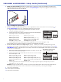
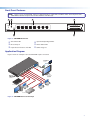
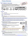
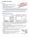
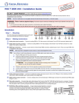
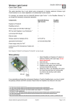
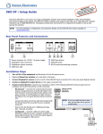
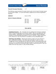
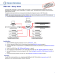
Product Category
SW6 HDMI and SW8 HDMI • Setup Guide
The Extron SW6 and SW8 HDMI are six and eight input, one output, High-definition Multimedia Interface (HDMI) switchers. They
allow multiple HDMI signals, including digital video, 3D signals, and embedded multi-channel digital audio, to be switched to one
compatible display. These switchers support all standard single link HDMI (up to 2.25 Gbps) and DVI 1.0 signal formats and are
compatible at 60 Hz with all PC resolutions up to 2048 x 1080 and HDTV resolutions up to 1080p with 12-bit color. They are fully
HDCP compliant.
This guide provides instructions for an installer to set up and operate these switchers. For full installation, configuration, and
operation details, see the SW HDMI Series User Guide, available at www.extron.com.
Rear Panel Features and Connections
NOTE: Figure 1 shows an SW8 HDMI, which has eight input connectors. The rear panel of the SW6 HDMI is identical except
for the number of input connectors (six).
6
100-240V
0.3A MAX
INPUTS
SW8 HDMI
OUTPUT
1
1
2
3
4
5
6
7
2 3
4 +V 5
6
7
8 +V
REMOTE
TALLY OUT
8
CONTACT
1
2 3
4 G 5
6 7
RS-232 AUTO
8 G
Tx Rx G
50-60Hz
2
1
3
5
4
Figure 1. SW8 HDMI Rear Panel
a
b
c
Female IEC power connector
HDMI input connectors
HDMI output connector
d
e
f
Contact closure port
RS-232 and auto-input switching connector
Tally Out port
Installation Steps
1. Turn off all of the equipment and disconnect it from the power source.
2. Mount the switcher on a rack shelf or furniture (optional. See the SW HDMI Series User Guide for the procedure).
3. Connect HDMI input sources to one or more of the SW HDMI input connectors (b on the rear panel diagram in figure 1).
NOTE:LockIt® cable lacing brackets, one for each HDMI input and output connector, are provided with the SW HDMI.
These brackets can be used to secure the HDMI cables to the rear panel connectors to reduce stress on the HDMI
connectors and prevent signal loss due to loose cable connections. For information on attaching the LockIt brackets,
see the SW HDMI Series User Guide, available at www.extron.com.
4. Connect an HDMI output device to the output connector (c).
By default, the EDID of this device is stored at the HDMI inputs.
RS-232 Auto
Tx Rx G
SW HDMI Series Switcher
Rear Panel
Remote Port
5. Connect control devices: Connect your computer to one of the
following SW HDMI communication ports to configure and control
the switcher via SIS commands:
zz
zz
RS-232 port — Connect the unterminated transmit, receive,
and ground wires of the RS-232 cable to the first three pins
on the provided 5-pole captive screw plug, as shown in the
illustration at right. Connect the plug to the rear panel Remote
shared connector (e in figure 1), and the other end of the
cable to your computer serial port. Protocol for the RS-232
port is 9600 baud, 8 data bits, 1 stop bit, no parity.
Config port — USB mini-B connector (f on the front panel
diagram on page 3) for USB control.
NOTE: If you use cable that has a drain
wire, tie the drain wire to ground at both ends.
Ground (G)
Receive (Rx)
Transmit (Tx)
Transmit (Tx)
Receive (Rx)
Computer or
Control System
RS-232 Port
1
SW6 HDMI and SW8 HDMI • Setup Guide (Continued)
6. Enable auto-input switching (optional). Use a jumper wire to connect pins 4 and 5 of the shared 5-pole captive screw
plug. Attach the plug to the remote connector (e on the rear panel diagram on the previous page) if this was not done in
step 5 for the RS-232 connection (see figure 2).
TE
MO
RE
UT
O
LY
TO
L
TA
UT
TP
OU
+v
1
1
TS
PU
IN
4
3
T
AC
NT
2
2
3
4
2
-23
RS
AU
Rx
Tx
CO
G
4
3
2
Figure 2. Enabling Auto-input Switching
1
7. Connect a contact closure device (optional). Connect a push-button contact closure device to the Contact port (d on
X
the rear panel diagram on page 1) to enable input switching via contact closure.
a.
Plug a 5-pole captive screw connector (provided) into one or both of the two
connectors of the dual Contact port.
REMOTE
TALLY OUT
b. Insert the signal wire of the contact closure device into the slot representing the
desired input number on the SW HDMI Contact port.
Pin 1 = Input 1 contact
Pin 2 = Input 2 contact
Pin 3 = Input 3 contact
Pin 4 = Input 4 contact
Pin 5 (G) = Contact ground
c.
Pin 6 = Input 5 contact
Pin 7 = Input 6 contact
Pin 8 = Input 7 contact (SW8 only)
Pin 9 = Input 8 contact (SW8 only)
Pin 10 (G) = Contact ground
1
2 3
4 +V 5 6 7
CONTACT
8 +V
1
2 3
4 G 5
8 G
6 7
RS-232
AUTO
Tx Rx
Contact Port for Input
Selection: SW6/SW8 HDMI
Insert the ground wire of the contact device into the G (ground) slot of the Contact port (pin 5 or 10).
Press the button on the contact closure device to switch the connected input to the output.
8. Connect an indicator device to the Tally Out port (optional). To identify the currently selected input when the front
panel buttons are not visible, connect a device such as an LED to the input and +V pins of the Tally Out port (f on the rear
panel diagram on page 1). When the input you are using is selected, the corresponding tally out pin shorts to ground, which
activates the connected indicator.
a.
Plug a 5-pole captive screw connector (provided) into one or both of the two Tally
Out connectors of the dual Tally Out port.
Tally Out Port for Input Selection
Indication: SW6/SW8 HDMI
b. Insert the power wire for the contact indicator device into the +V slot of the Tally
REMOTE
Out connector (pin 5 or 10).
Pin 1 = Input 1 tally ground
Pin 2 = Input 2 tally ground
Pin 3 = Input 3 tally ground
Pin 4 = Input 4 tally ground
Pin 5 = +5 V
c.
TALLY OUT
Pin 6 = Input 5 tally ground
Pin 7 = Input 6 tally ground
Pin 8 = Input 7 tally ground (SW8 only)
Pin 9 = Input 8 tally ground (SW8 only)
Pin 10 = +5 V
1
2 3
4 +V 5 6 7
CONTACT
8 +V
1
2 3
4 G 5
8 G
6 7
RS-232
AUTO
Tx Rx
Insert the ground wire for the indicator into the slot on the Tally Out port that represents the input that you want to
monitor (pin 1, 2, 3, 4, 6, 7, 8, or 9).
Example: One way to use this port is to connect it to a contact closure device with an LED. Connect the contact device to
the Contact port as well. When you use the contact device to switch the input that you are using, the LED lights.
9. Power on the output display.
10. Connect power to the switcher.
11. Power on the source devices.
2
Product Category
Front Panel Features
NOTE: Figure 3 shows an SW8 HDMI, which has eight input buttons, input LEDs, and HDCP LEDs. The front panel of the
SW6 HDMI is identical except for the number of buttons and LEDs (six).
1
2
AUTO
SWITCH
IR
4
3
INPUTS
1
2
3
INPUTS
4
5
6
7
OUTPUT
SIGNAL
8
1
2
3
4
5
6
7
8
HDCP
CONFIG
SW8 HDMI
HDMI SWITCHER
6
5
Figure 3. SW8 HDMI Front Panel
a
b
c
d
e
f
Auto Switch LED
IR receiver port
Input Selection buttons and LEDs
Input and Output Signal LEDs
HDCP Status LEDs
USB Config port
Application Diagram
Figure 4 shows an example of how an SW8 HDMI may be connected.
TouchLink
Control
System
VCR
DVD
DOC
CAM
LAPTOP
PC
ON
OFF
DISPLAY
MUTE
SCREEN
UP
SCREEN
DOWN
MI
8 HD
SW
TCP/IP
TE
MO
RE
TO
1
2
3
UT
TP
6
5
+V OUT
4
LLY
TA
T
AC
NT
CO
OU
1
2
3
4
G
5
6
7
8
+V
AU
2
-23
RS
Tx
7
8
Rx
G
G
®
100
INPUT
IR
RELAY
LINK
3
ACT
1
3
1
COM
RX
8
HDMI
Cables
IPL
250
4
3
2
1
4
TX
2
1
2
R
4
2
3
RS-232
7
6
TS
PU
IN
5
4
3
2
X
A MA
0.2
0V
-24
1
Flat Panel
Display with
Integrated
Speakers
100
Extron
SW8 HDMI
z
60H
50-
HDMI
Cables
Switcher
Blu-ray Player
Laptop
Laptop
PC
Laptop
DSS Receiver
Figure 4. SW8 HDMI Connection Example
3
Extron Headquarters
+1.800.633.9876 (Inside USA/Canada Only)
Extron USA - West
Extron USA - East
+1.714.491.1500+1.919.863.1794
+1.714.491.1517 FAX
+1.919.863.1797 FAX
4
Extron Europe
+800.3987.6673
(Inside Europe Only)
+31.33.453.4040
+31.33.453.4050 FAX
Extron Asia
+65.6383.4400
+65.6383.4664 FAX
Extron Japan
+81.3.3511.7655
+81.3.3511.7656 FAX
Extron China
+86.21.3760.1568
+86.21.3760.1566 FAX
© 2013 Extron Electronics All rights reserved.
Extron Middle East
+971.4.299.1800
+971.4.299.1880 FAX
www.extron.com
Extron Korea
+82.2.3444.1571
+82.2.3444.1575 FAX
Extron India
1800.3070.3777
(Inside India Only)
+91.80.3055.3777
+91.80.3055.3737 FAX
68-2312-51 Rev. A
06 13