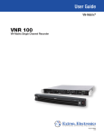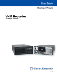
1
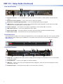
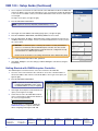
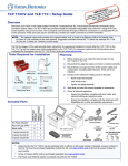
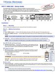
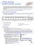
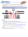
VNR 100 • Setup Guide
The Extron VNR 100 recorder is a network storage device capable of recording and playing back PURE3 video, audio, and
data streams from VN‑Matrix codecs and encoders in a VN-Matrix system. The system must be under the control of an Extron
VNM Enterprise Controller.
This guide provides basic instructions for an experienced installer to configure and operate a VNR 100 recorder.
NOTE: For complete instructions about mounting, installation, and network configuration, see the VNR 100 User Guide and
the VNM Enterprise Controller User Guide at www.extron.com.
TouchLink™ Touchpanel
External User Control
VN-Matrix
VNR 100
Recorder
VNR 100 Recorder
Browser Based User
Control
Network
VNM Enterprise Controller
VN-Matrix
VNR 100
Recorder
Multicast Enabled
Network
VNR 100 Recorder
LAN-1
LAN-2
STATUS
LAN-1
LAN-2
STATUS
VN-MATRIX 225 SERIES
VN-MATRIX 225 SERIES
RGB/DVI OVER IP
RGB/DVI OVER IP
LAN-1
LAN-2
STATUS
LAN-1
LAN-2
STATUS
VN-MATRIX 225 SERIES
VN-MATRIX 225 SERIES
RGB/DVI OVER IP
RGB/DVI OVER IP
LAN-1
LAN-2
STATUS
LAN-1
LAN-2
STATUS
VN-MATRIX 225 SERIES
VN-MATRIX 225 SERIES
RGB/DVI OVER IP
RGB/DVI OVER IP
Multiple VNM 200 and 225 Series Encoders
(or CODECs configured as encoders)
Multiple VNM 200 and 225 Series Decoders
(or CODECs configured as decoders)
Installation
1. Mount the VNR 100 using the provided rack mount kit (see Mounting, below).
2. Connect a standard IEC power cord to the rear panel connector (see Rear Panel Features on page 2).
3. Connect the VNR 100 to the same network as the VNM Enterprise Controller, using Ethernet port 0 (see Rear Panel Features
on page 2).
4. Power on the VNR 100 (see VNR 100 Power Up Procedure on page 3).
5. Use a computer on the same network to carry out the initial configuration (see VNR 100 Initial Configuration on page 3).
6. Use the VNM Enterprise Controller to configure the VNR 100 (see Getting Started with the VNM Enterprise Controller on
page 4).
7. If it becomes necessary to power down the VNR 100, see VNR 100 Power Down Procedure on page 3.
Mounting
The VNR 100 can be mounted in a rack, using the provided kit. See the VNR 100 User Guide at www.extron.com for UL
guidelines for rack mounting and complete mounting instructions.
1
VNR 100 • Setup Guide (Continued)
Rear Panel Features
b d
a
c d
e
f
g h
a
AC power connector — use a standard IEC power cord to connect the recorder to a 100 to 240 VAC, 50 or 60 Hz power
source.
b
c
d
PS/2 port for mouse (optional) — connect a PS/2 mouse to this port, if required.
e
f
g
h
RS-232 control port — use an Extron control cable (not provided) to connect the VNR 100 to a control PC.
PS/2 port for computer keyboard (optional) — connect a PS/2 keyboard to this port, if required.
USB ports (2) — may also be used to connect a mouse and keyboard for initial configuration. In total, there are four USB
inputs, two on the rear panel and two on the front panel.
VGA output connector — connect a local VGA monitor to this output.
Ethernet port 0 (eth0) — use an RJ-45 cable to connect this port to the primary network (the VN-Matrix network).
Ethernet port 1 (eth1) — is not functional. Do not connect this port to the network.
Front Panel Cover
The front panel has a lockable cover to prevent unauthorized access to the removable drives. When the cover is in place, the DVD
player, USB ports, and serial ports are not available for use. To install or remove the front cover, see the VNR 100 User Guide at
www.extron.com.
Handle
VN-Matrix
VNR 100
Recorder
Front Panel Features
a
b
h
2
i
c c
d
j
e fg
a
j
a
Handles (2) — for sliding the unit in and out of the mounting rack and securing the front panel bezel. Do not use the handles
for lifting the recorder.
b
c
CD and DVD drive — used for system updates or software installation.
d
RS-232 Comm port — Insert a 9-pin RS-232 cable to connect the unit to a control PC.
USB ports — used to connect a mouse and keyboard for initial configuration. There are a total of four USB ports: two front
panel and two rear panel.
e
Status LEDs — five LEDs providing information about:
i
Overtemperature
a.
2
1
Network
Activity (2)
Network
Activity (1)
Drive
Activity
Power
The Overtemperature LED flashes yellow when a fan fails. It lights yellow solidly when the internal temperature is too high
(this may be caused by high ambient temperature or a fan that is obstructed).
b. Network 2 is not active, so this LED does not light.
c.
The Network Activity (1) LED flashes green when there is activity on Network 1.
d. The Drive Activity LED flashes yellow when the hard drive is in use.
e.
The Power LED lights green when the unit is receiving power.
f Reset button — is used to reboot the VNR 100.
g
Power button — used to apply or turn off the main power. When main power is turned off, standby power is actively
supplied to the recorder.
h
i
j
OS drive — houses the solid state operating system drive (removable).
Media drive — houses the media drive (removable).
Spare drive bays (2) — are not used. They must not have drives fitted.
ATTENTION:
• Do not remove the OS drive or media drive while the VNR 100 is powered on.
• For complete instructions about replacing the OS drive, see the VNR 100 O/S Drive Replacement Kit Installation
Guide at www.extron.com.
• For complete instructions about replacing the media drive, see the VNR 100 Media Drive Replacement Kit
Installation Guide at www.extron.com.
VNR 100 Power Up Procedure
NOTE: Before powering up the VNR 100, ensure all necessary devices are connected correctly and powered up.
Power up the VNR 100 by pressing the power button (see Front Panel Features figure, g). The VNR 100 boots up.
VNR 100 Power Down Procedure
Power down the VNR 100 by pressing and releasing the power button (see Front Panel Features figure, g). Ther recorder takes
approximately 20 - 30 seconds to power down.
VNR 100 Initial Configuration
Network Considerations
Before connecting the VNR 100 recorder to the network, you need to know the network settings of both the VNR 100 and the
VNM Enterprise Controller. The following are the default settings. Check with your network administrator to be sure they still apply
to your unit:
Network settings (ETH0)
Controller
Configuration
IP address
192.168.254.254
Subnet mask
255.255.255.0
Gateway address
192.168.254.253
Port
8080
IP address
192.168.254.254
Port
5432
User name
config
Password
config
3
VNR 100 • Setup Guide (Continued)
1. Use a computer connected to the same network as the VNR 100. In the browser address bar,
enter the IP address of the recorder, followed by a colon (:) and the port number. By default, this
is 192.168.254.254:8080. Contact your network administrator to be sure these values have
not changed.
The login screen opens (see figure at right).
2. Enter the Username and Password.
NOTE: By default, both the Username and Password are config.
3. Click Login. The VNR 100 Recorder Settings page opens (see figure at right).
4. Enter the IP Address, Subnet Mask, and Gateway Address of the recorder.
Logout
5. Enter the Controller IP address, Controller port number and maximum transmission
unit (MTU) setting for the controller. Contact your network administrator to ensure you have
the correct values.
VNMatrix recorder settings
Network settings [eth0]
IP Address
ATTENTION:The VNM Enterprise Controller port number is used by all VN-Matrix
devices to communicate with the VNM Enterprise Controller. The value should
only be changed if the VNM Enterprise Controller has been configured to accept
communications on a different port number.
192.168.254.254
Subnet Mask
255.255.255.0
Gateway
192.168.254.253
Serial
1111999
Controller IP
192.168.254.254
Controller port
5432
MTU
1500
Recorder settings
User settings
New password
Under normal circumstances, the setting should remain at the default value (5432).
Confirm New password
Data disk
Umount
status:
Disk free space:
Format
6. Enter a New password and Confirm New password.
mounted to /home/matrix_rec/Recording_Files
19GB->98% used
formated to ext3
Apply Changes
Cancel Changes
7. Click Apply Changes to save the settings (or Cancel Changes to exit without saving the
information).
Getting Started with VNM Enterprise Controller
The VNM Enterprise Controller must be on the same network as the VNR 100.
1. Use a PC on the same network as the controller to access the controller website. In
the browser address bar, enter the controller IP address. The Login screen opens (see
figure at right).
2. Enter the Username and Password.
NOTE: By default, for the VNM Enterprise
Controller, the Username is admin. Leave
the Password blank (no entry is required).
3. Click Login. The Enterprise Controller device list
opens (see the figure to the right).
4. Check the box next to the VNR 100 recorder. A
series of action buttons appear at the bottom of
the screen (see figure below).
See the Enterprise Controller User Guide (at
www.extron.com) for complete information
about configuring and using the VNR 100.
Extron Headquarters
+1.800.633.9876 (Inside USA/Canada Only)
Extron USA - West
Extron USA - East
+1.714.491.1500+1.919.850.1000
+1.714.491.1517 FAX
+1.919.850.1001 FAX
4
Extron Europe
+800.3987.6673
(Inside Europe Only)
+31.33.453.4040
+31.33.453.4050 FAX
Extron Asia
+65.6383.4400
+65.6383.4664 FAX
Extron Japan
+81.3.3511.7655
+81.3.3511.7656 FAX
Extron China
+86.21.3760.1568
+86.21.3760.1566 FAX
Extron Middle East
+971.4.299.1800
+971.4.299.1880 FAX
© 2013 Extron Electronics All rights reserved. www.extron.com
Extron Korea
+82.2.3444.1571
+82.2.3444.1575 FAX
Extron India
1800.3070.3777
Inside India Only
+91.80.3055.3777
+91.80.3055.3737 FAX
68-2237-50 Rev. A
05 13