1
CB ELECTRONICS
Loddonside, Lands End House, Beggars Hill Road, Charvil, Berks RG10 0UD, UK
Tel: +44 (0)118 9320345, Fax: +44 (0)118 9320346, www.colinbroad.com
SR/MR/RM/Video Slave
Serial Remotes/Synchronizers
Technical Manual
Contents
T1.00 MACRO LIST
T1.01 MACRO'S 65-90
T1.02 MACRO'S 91 - 120
T1.03 MACRO's 121-150
T1.04 Macro's 151-165
T1.05 DAT Specific Macro's
T1.06 MR Video Streamer Specific Macro's
T1.07 ADR/Taker Specific Macros
T1.08 ID << / ID >>
T2.00 READY KEY'S
T2.10 MACHINE READY BANK
T2.20 SYSTEM READY BANK
T2.30 SYSTEM RECORD READY TRACK ASSIGNMENTS
T2.31 CRASH RECORD ENABLE
T3.00 Machine Connection
T3.01 RS422 Protocols
T3.02 Audio Machines
T3.03 RS422 Inputs & Outputs
T3.04 SR-3 Port A / SR-24 & RM-6 Port E
T3.05 Self Test
T4.00 MACHINE INTERFACE DETAILS
T4.01 FOSTEX D10
T4.02 FOSTEX D20
T4.03 FOSTEX D25
T4.04 FOSTEX D30
T4.05 TASCAM DA-88/SONY PCM-800
T4.06 TASCAM DA-98
T4.07 TASCAM DA-60
T4.08 TASCAM MMR-8
T4.09 SONY PCM-3324S
T4.10 SONY BETACAM
T4.11 SONY DVW-A500P
T4.12 SONY PCM-7040
T4.13 SONY PCM-7030
T4.14 SONY VO-9800/VO-9850
T4.15 STUDER TLS4000 Mk I
T4.16 STUDER TLS4000 Mk II
T4.17 STUDER D820/D827
T4.18 DAR SABRE
T4.19 DAR OMR-8
T4.20 AKAI DR-8
T4.21 AKAI DD-8
T4.22 AKAI DD1500
T4.23 SSL SCREENSOUND
T4.24 SSL AXIOM
T4.25 AVID AUDIOVISION
T4.26 AVID NEWSCUTTER
CB Electronics
SR/MR Technical Manual
26 October 2012 SR-Tech 1
T4.27 CB BS-1/MC-1
T4.28 DOREMI V1
T4.29 FAIRLIGHT MFX-3
T4.30 Audio Kinetics ES-1.11/1.12
T4.31 Augan
T4.32 VPR-3 with Adrienne Interface
T4.33 Timeline Lynx
T4.34 FED Audio Solution
T4.35 NAGRA T
T4.36 Sony DNW-A75/A100 SX Digital Video Hybrid
T4.37 FED V-MOD 100
T4.38 PUBLISON CP+
T4.39 BTS DCR 500
T4.40 STUDER V-8
T4.41 Diva
T4.42 Otari Radar-1 revision 1.46
T4.43 SSL G Series Computer (4K/5K)
T4.44 Sony BVU-800 (Using timecode from an audio track)
T4.45 Ampex DCT-700
T4.46 Sony PCM-3402
T4.47 Studer D950
T4.49 Philips DCR 6024 Voodoo
T4.50 Midi Machine Control (MMC)
T4.51a Tascam MX-2424 Midi Interface
T4.51b Tascam MX-2424 P2 Interface
T4.52 Tascam DA-78HR
T4.53 JVC CR-600U
T4.54 Panasonic AG-DS850
T4.55 360 Systems TCR-4, TCR-8
T4.56A Pioneer DVD-V730D
T4.56B Pioneer Cable
T4.57 Sony MSW-M2000P Beta-Sp, Digi-Beta, Beta-SX, IMX
T4.58 Accom WSD/HD
T4.59 Sony DMX-R100
T4.60 FEG Prima SY2
T4.61 Harrison Series 12 and MPC
T4.62 Fostex D-15
T4.63 Fairlight Vivid
T4.64 Leitch Video Server 420,440
T4.65 AMS Encore
T4.66 Genex 8500
T4.67 Sony DSR 2000
T4.68 Sony J3 Player
T4.69 Panasonic AJ-3700AE D5-HD
T4.700 Digi-Design HD 5.3.1cs3
T4.701 Protools 5.0 - USD
T4.702 Digi-Design Protools 5.1.1
T4.703 Protools Windows 6.2 PC
T4.704 Digi-Design Protools 6.2.2 MAC
T4.705 Pro-Tools LE 6.1.1
T4.706 Digi-Design Protools Summery
T4.71 Pyramix Virtual Studio
T4.72 Euphonics System 5 Console
T4.73 Harrison IKIS
T4.74 Sondor Nova
T4.75 Pro-Tools LE 6.1.1
T4.76 Waveframe
T4.77 Soundtracs DS-00
CB Electronics
SR/MR Technical Manual
26 October 2012 SR-Tech 2
T4.78 NUENDO Version 2.0 build 33
T4.79 Merging V-Cube
T4.80 Soundmaster Atom
T4.81 Omneon Spectrum
T4.100 SSL 4K/5K Computer
T4.101 Studer Vista Console
T5.0 CONNECTION DIAGRAMS
T5.01 Power Supply Connector
T5.02 Video Sync Connector
T5.03 Sony 9-PIN Cable
T5.04 Tx-Rx Invert Sony 9 pin Cable
T5.05 DA-88 15-PIN Cable
T5.06 Audio kinetics ES1.11/1.12 Cable
T5.07 GP PORT CONNECTIONS
T5.08 S29 Remote (SR24A Only)
T5.09 SR-24H (6 Port) Harrison Computer Interface
T5.10 Sony 9 pin CABLE With Power supply
T5.11 RS232 (PC Link) CABLE
T5.12 RS232 (PC Link) CABLE (SR-24 ports E & F)
T6.0 SERIAL INPUTS
T6.01 How many inputs
T6.02 Input Protocols
T6.02 How Menu Settings change inputs
T7.0 Sync optimisation
T7.00 Multi Machine Synchronizer Set Up
T7.10 Deciding between the SR/MR Synchronizer or the Machine's built in synchroniser.
T7.20 Optimisation of the SR/MR Synchroniser.
T7.21 Sync type
T7.22 Park Ahead
T7.23 Machine Start-up Delay (Play/Advance)
T7.24 Pre-Roll
T7.25 Post Roll
T7.26 Delay
T8.0 Fault finding
T9.0 Video Synchroniser (VS-1) Interface
T9.01 Video Streamer Setup
T9.02 SR Wipe-length Setup
T9.03 Video Streamer Interface to the SR System
T9.04 Video STreamer Interface to the MR System
T10.0 Service and installation Diagrams
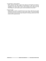
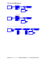
T10.01 SR-3 and SR-4 Connections
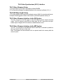
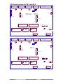
T10.02 SR-24 and SR-32 Connections
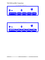
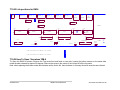
T10.03 Typical RM-6 Systems
T10.04 Link positions for SR-3 and SR-4
T10.05 Link positions for RM-6
T10.06 How To Open RM-6
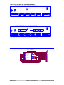
T10.07 RM-6, Xmc Hub and Video Slave Connections
T10.08 S29 Parallel remote Connections (RM-6, SR-24A & SR-32 Only)
T10.09 SR-4, SR-5 GPI Connections
T10.10 RM-6N GPI Connections
A1.0: System Setup Map
CB Electronics
SR/MR Technical Manual
26 October 2012 SR-Tech 3
A2.0: System Record Map
CB Electronics
SR/MR Technical Manual
26 October 2012 SR-Tech 4
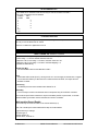
T1.00 MACRO LIST
To change the macros Root | Unit | Generic | Menu 30: Macro protection must be set to 0=Off
For more information see section 7.30 of the user manual.
A list of all user macro's available in table form. Macro's prefixed by * are only available with larger
EPROM's
CB Electronics
SR/MR Technical Manual
26 October 2012 SR-Tech 5
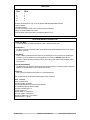
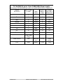
T1.01 MACRO'S 65-90
No.
Description
65
BANK: The Bank key will select between blocks of record channels dependant on Root | Unit
| Rec | Menu 07:- Track Arm Keys.
66
LOOP: Loop current machine between Record in and record Out
67
Assign Record keys to current Machine
68
Shifter Reset: The shifter is used as a temporary offset that is added to the current offset.
The Shifter Reset key clears the shifter offset. Store followed by Shifter Reset will add the
contents of the shifter memory to the current offset and clear the shifter.
69
Shifter Decrement:
70
Shifter Increment:
71
Locate Start:
72
LOCAL: (Disables 9 pin Input's when LED illuminated)
73
Mark: Grab current machine time
Store Followed by Mark = Mark Sync
Recall Followed by Mark = Find specified Mark point
Shift Followed by Mark = Reset Mark Pointers
74
Instant Record: Locate -3 seconds and enter record, to change the relative locate use
[Store] followed by Macro Key
75
Record Out Enable/Disable, Record out is enabled when illuminated
76
Auto-Record:
77
Manual Record:
78
Review:
79
Rehearse:
80
LS Mute:
81
Auto/Manual Record: Use [Shift] to access manual record
82
Rehearse/Review: use [Shift][ to access Review
83
All-Stop: All-Stop + All Chase Off
84
Locate:
85
Set Generator
86
Variplay
87
Track Arm Keys: Follow Selected Mcn
88
Track Arm Keys: Follow Enabled Mcn
89
Sondor: Framing /Focus: use [Shift] for Focus (Use with ID+ & ID- keys)
90
Erase ID: Erase DAT ID
CB Electronics
SR/MR Technical Manual
26 October 2012 SR-Tech 6
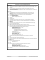
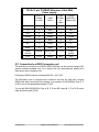
T1.02 MACRO'S 91 - 120
No.
Description
91
Out Overlap: Extend the record out point
Enter Time followed by [Store] followed by [key] to Set
92
PNO Erase: Erase PNO
93
Pno Find: Find DAT PNO
94
ID <- : (See Section T1.08)
95
ID -> : (See Section T1.08)
96
Spare:
97
*Show Dif: Display Reader-Serial Difference
98
*Constant Offset:Fix Offset
99
*48KHz: Set Sampling Freq. @ 48KHz
100
*44.1: Set Sampling Frequency @ 44.1KHz
101
Crawl Reverse: One frame per second reverse
102
Crawl Forward: One frame one secon forward
103
Record Assign 1 (Use Store to set machine number)
104
Record Assign 2 (Use Store to set machine number)
105
Record Assign 3 (Use Store to set machine number)
106
Record Assign 4 (Use Store to set machine number)
107
Record assign 5 (Use Store to set machine number)
108
Enable/Disable Delayed Play when locate finished
109
Ready EE: Switch All Record Ready channels between Input and Replay Monitor
110
EE: Switch current machine between Input and Replay Monitor
111
Tape Mon: Switch current machine to Replay Monitor
112
FEET: Timecode Display / Footage Display (Shift followed by Feet = Local Time Display)
113
Reader: Display Timecode Reader, Recall followed by Reader will display Generator
114
Prev: Previous Loop
115
Next: Next Loop
116
Join: Join Loop
117
Insert: Insert loop
118
Generator: Display Generator, Recall followed by Generator will display Reader
119
Shuttle:
120
Jog:
CB Electronics
SR/MR Technical Manual
26 October 2012 SR-Tech 7
T1.03 MACRO'S 121 - 150
No.
Description
121
I-Replay:Instant Replay
122
Record Ready 1: Assignable to any machine/track, enter the machine number as Seconds,
the track number as frames followed by Store followed by Key.
123
Record Ready 2: as per Record Ready 1.
124
Record Ready 3: as per Record Ready 1.
125
Record Ready 4: as per Record Ready 1.
126
Step Forward +1:- To step fwd 1 frame hit once, to move fwd 5 frames hit 5 times.
127
Step Reverse -1: To step back 1 frame hit once, to move back 5 frames hit 5 times.
128
*Loc 1: Locate Memory 1
129
*Loc 2: Locate Memory 2
130
*Loc 3: Locate Memory 3
131
Reverse Play
132
AGAIN: Locate Last Playback Start (2 Levels)
133
AGAINP: Again with Play, Shift Again: Instant Loop, Loop from Play Start to here.
134
Wind @ *2: both fwd and rvs wind commands are converted to shuttle at 2* play speed.
135
Wind @ *4:
136
Wind @ *6:
137
Eject: Eject Current Machine, Shift followed by Eject = Eject All
138
Key Lock: Locks out the following keys:Machine Selection, Chase On/ Off, Record Machine Selection(MR only)
139
Machines MR: Show Individual Machine status on 2 Line Display
140
Cue: Locate Record In
141
*Comm Enable: Communication Enable/Disable
142
Local Time:Select LOCAL TIME/Timecode
143
Rec Enable: Record Enable On/Off
144
*Red Light: Manual Red Light Switch
145
*Preview: Sony Preview Command
146
*Review: Sony Review Command
147
*S.Auto: Sony Auto Edit Command
148
*Pre-Roll: Sony Pre-Roll Command
149
*Set TG-1: TG-1 Set Reader
150
*Post Sync: One Key Post Sync 'D', Position Master so that the Timecode Slate is visible,
Enter the timecode number displayed, hit this key and the offset is calculated for machine 'D',
the current video position is set as Record In, and a Chase-On command is sent to Machine
'D'
CB Electronics
SR/MR Technical Manual
26 October 2012 SR-Tech 8
T1.04 Macros 151 - 165
No.
Description
151
*REC IN +1: Add one minute to Record in, subtract one minute from all offsets, Locate new
record in.
152
*Red Light OFF: Disable Red Light output
153
*Red Light Auto: Auto Red light
154
*Mute: Mute Always
155
*Auto Mute Enable: When enabled, mute output except as defined by Root | Unit | Generic
| Menu 34: GP Output 3
156
*PARALLEL Command Enable: MR Only
157
*PARALLEL Record Command Enable: MR Only
158
*Spare
159
*Serial A(E) type: Set Serial A(E) INPUT(illuminated)/OUTPUT(Off)
160
*Spare
161
*Standby:
162
*Edit Loops:
163
*Select Master: Select master (Used when programming User Macro's)
164
SPARE
165
SPARE
166
Instant Loop: Loop from Last Playback Start to Here
167
Instant Locate: Locate Last Playback Start
168
*Scrub: 7050/7040 Ram Scrub (Was Locate see 84)
169
*Sony: Set Current Port to Sony Protocol:
170
*SX/D88: Set Current Port to Sony SX/Tascam D88 Protocol:
171
*D827: Set Current Port to Studer D820/D827 Protocol:
172
*TLS: Set Current Port to Studer TLS 4000 Protocol:
173
*Lynx: Set Current Port to Timeline Lynx/Ampex Protocol
174
*ES Bus: Set Current Port to Audio Kinetics ES1.11 Protocol
175
*Clear Offsets: Shift= Clear All Offsets and Chase (Same as Shift Master-Chase/Offset)
176
*Field -: Previous Field Ampex Protocol only
177
*Field +: Next Field Ampex Protocol only
178
*Instant Lock: (Shift Chase)
179
*Make Master: (Shift Machine Key)
180
*Instant Fwd: Locate 10 Seconds ahead then Play ( As Instant Replay)
181
*Doremi V-1: Play Segment / Ampex: Freeze
182
*Doremi V-1: Select Segment / Ampex: Edit Optimize
CB Electronics
SR/MR Technical Manual
26 October 2012 SR-Tech 9
183
*Doremi V-1: Define Segment / Video Editor: Display Group
Macro's 184 - 200
184
*Record Enable: Current Machine Record Enable/Disable
185
Record Track Map: Custom 1
186
Record Track Map: Custom 2
187
Record Track Map: Machine Map 1
188
Record Track Map: Machine Map 2
189
*Sync: Constant Offset Mode On/Off
Shift,Sync: CMaster Chase On
190
*Cue: Locate In point
191
*Park: locate preroll before in point
192
*Insert: Video Streamer Insert On/Off (MR Only)
193
Data: Video Streamer Data line On/Off (MR Only)
194
195
196
197
Delete All: Video Streamer Delete all cues
198
*Dec Offset: Decrement Offset
199
*Inc Offset: Increment Offset
200
Dec Take: Decrement Take number (Shift to Undo)
201
Auto Map System Record Tracks: Map all tracks of Record enabled machines
202
203
204
205
CB Electronics
SR/MR Technical Manual
26 October 2012 SR-Tech 10
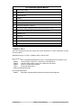
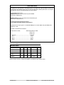
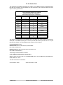
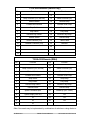
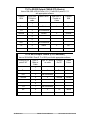
T1.05 DAT Specific Macro's
Description
Macro
No.
Sony PCM7030
Fostex
D25
Auto-ID Write
88
PNO Renumber
89
O.K.
YES
Erase ID
90
O.K
(Illegal)
YES
Write Specified PNO
91
Start ID
only
YES
Erase Specified PNO
92
Find Specified PNO
93
O.K.
YES
Previous ID
94
O.K.
YES
Next ID
95
O.K.
YES
Fostex
D30
NO
T1.06 MR Video Streamer Specific Macro's
192
All Insertions On/Off, Shift Macro = BVB Mode On/Off
193
Data Line On/Off
194
Previous Data
195
Next Data
196
Delete Current Cue, Shift Macro = Delete All Cues
197
Delete All Cues
Other Non Specific Macro's
112
Feet: Change Insert to Feet
142
Local Time: Change Insert to Local Time
If The Record/Lock Flag is enabled on the Video Streamer then a Box will be inserted next to the
timecode insert when the system is locked, a R will indicate when the system is in Record.
CB Electronics
SR/MR Technical Manual
26 October 2012 SR-Tech 11
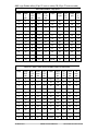
T1.07 ADR/Taker Specific Macros
75
Record Out Enable:
76
Auto record
77
Manual Record
78
Review
79
Rehearse
81
Auto record: Shift Macro = Manual Record
82
Rehearse: Shift Macro = Review
94
Previous ID: When ADR Mode Active this becomes Previous Loop
95
Next ID: When ADR Mode is Active this becomes Next Loop
114
Previous Loop
115
Next Loop
116
Join Loop, Keep Current In- time and change Out-Time to Next Out Time
117
Insert Loop: Shift Macro: Delete Current Loop
T1.08 ID << / ID >>
These are multi-purpose keys that change their function dependant on various parameters, the logic
used is as follows:[Shift] followed by [ID <<] or [ID >>] Display current in and out points
[ID <<] or [ID >>]
If
Auto record/Rehearse/Man/Review active or Loop displayed then Previous/Next Loop
Else-If
Current machine is type DAT1 or DAT2 then :-Previous/Next ID
Else-If
VARI-PLAY/Slow-motion is active then:- Reduce/Increase speed
Else-If
Doremi V1 Previous/Next Segment
Else-If
Sondor then adjust focus +/Else Previous/Next Mark point
Not currently implemented:Else-If
MR System and Giant Display fitted then Decrease/Increase Brightness
CB Electronics
SR/MR Technical Manual
26 October 2012 SR-Tech 12
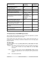
T2.00 RECORD READY KEY'S
The Record Ready keys operate in three different ways as defined in Root | Unit | Record | Menu 7:
Track Arm Keys
The three Settings are defined as follows:0= System Record Ready
The Record Ready keys may access any track on any machine controlled (Maximum 4) the bank key
controls access to a maximum of 48 tracks. The number of banks is set by the setup menu.
1= Machine Record Ready
The Record ready keys control the currently selected machine only, the bank key allows access the
tracks available on the currently selected machine.
2= Record Enabled Machine Ready
The record ready keys are assigned to the last record enabled machine selected.
3= Macro
The record ready keys are assigned by macro keys as follows
Macro 103..107: Ports A..E
Macro 176: System Record
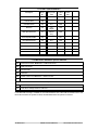
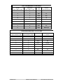
T2.10 MACHINE RECORD/RECORD MACHINE READY BANK
The machine ready bank switch is used to access the all record tracks of the currently selected machine
using Record Ready switches 1-T2.
MACHINE/RECORD MACHINE READY BANK SWITCH
Record Command Type >
1= Analog
2= 8 Track
3= 16 Track
4= 24 Track
Bank 1
A1..A4+ Video
D1..D8
D1..D8
D1..D8
Bank 2
Not Available
A1..A4+
Video
D9..D16
D9..D16
Bank 3
Not Available
Not Available
A1..A4
D17..D24
Bank 4
Not Available
Not Available
Not Available
A1..A4
T2.20 SYSTEM READY BANK
The System ready bank key is used to access all the system record ready switches using the first eight
record ready switches as follows:-
SYSTEM READY BANK SWITCH
CB Electronics
Bank 1
System Ready 1-8
Bank 2
System Ready 9-16
Bank 3
System Ready 17-24
Bank 4
System Ready 25-32
Bank 5
System Ready 33-40
Bank 6
System Ready 40-48
SR/MR Technical Manual
26 October 2012 SR-Tech 13
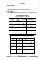
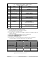
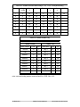
T2.30 SYSTEM RECORD READY track assignments
This controller will work with both Audio and Video machines, track assignment is complicated by this.
The digital audio track assignment is simple, tracks 1-48 are numbered 1-4T2. The Video, Assemble and
analog tracks are numbered as assigned in the table below.
Analog and Video Track Numbers
Track
Number
Track
Number
Track
Number
Analog 1
49
Analog 3
51
Video
53
Analog 2
50
Analog 4
52
Assemble
54
System record ready switches may access any machine in the system. The machine and track are
specified by entering the machine number as seconds and the track as frames followed by STORE then
Record Ready key. For example to set up a Record Ready key 5 for machine C track 5 :[Keybd] 00:00:03:05
[Shift]
[Store]
Ready Key 5
Mc:Trk 00:00:03:05
RECALL
TRIM+
Followed by a Record Ready key will display the selected Machine/Track for that key.
Followed by a System Record Ready key will increment the previous Track and store in
the selected key.
T2.31 CRASH RECORD
Record Ready 56 is used as crash record Enable. When a crash record command (Record and Play
from Stop) is issued ALL machines that are Crash Record Enabled (Analog+Video Track Arm 8) will
enter Record. When terminated (Play or Stop) all machines that are in crash record will STOP, Crash
record will then be disabled.
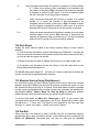
T3.00 Machine Connection
T3.01 RS422 Protocols
There are several different RS422 protocols available, the most common is Sony P2. This was
developed to control and synchronize video machines, Video machines that are designed to be used
with RS422 video editors they make very good slaves. No video machine with the exception of some
non-linear machines have built in synchronizers.
T3.02 Audio Machines
Audio machines that have RS422 control will normally have built in synchroniser. These machines are
often optimised using the built in synchroniser, the RS422 control can be very basic. When controlling a
machine with a built in synchroniser the user has two choices.
1) Use the machine synchroniser: connect both the RS422 and timecode output of the SR to the
timecode input of the machine.
2) Use the SR synchroniser: connect the RS422 only to the machine
Provided that the machine supports the appropriate commands the operation will be identical. In
installations where only the RS422 connection is possible then the SR synchroniser must be used.
Where the machine synchroniser is used it is preferable to use the timecode output of the SR. This will
enable the operator to change the master machine without changing the timecode feed to the slave
machines and allow group locates when selected.
The SR internal sync routines provide the user with a number of menu selections options and controls,
these are described in section 10.43.. A single global setting (10.12 Use Master Timecode) will determine
the use of Machine or SR synchroniser when a machine is initially connected.
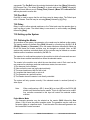
T3.03 RS422 Inputs & Outputs
Every RS422 connector has both input and output connections, the Sony manual describes Controlling
CB Electronics
SR/MR Technical Manual
26 October 2012 SR-Tech 14
and Controlled devices. To simplify this we normally talk about RS422 inputs (Controlled Devices) and
RS422 outputs (Controlling devices). The Controlling device (Editor, Synchroniser..) has an RS422
output, the controlled device (Machine) has an RS422 input.
To complicate matters the connectors on both controlling (output) and controlled (input) devices are
nearly always a female. Some RS422 connections (SSL, CB SR port A, Akai, Avid, DAR ..) can be
software switched between outputs (controlling) and inputs (Machine emulation). With these machines
care must be taken with the connecting cable to ensure that Tx (Transmit) is connected to Rx (Receive).
The options are as follows:1) Switch the Rx and Tx connections automatically:- Akai
2) Switch the Rx and Tx connections with Links:- CB SR-4/3
3) Provide special Machine emulation cables:- Avid
4) Require a Tx-Rx Invert cable: SSL, DAR
T3.04 SR-3 Port A / SR-24 & RM-6 Port E
Port A on the SR may be configured as an Input or as an Output in software. as follows:1) Select Root | Unit | Generic | Menu 31: Serial A Type and select type 1= Input.
2) Either use a TX-Rx invert cable to connect to port A where the 4 internal links are configured as a SR4 (Vertical to back panel), or Change the 4 internal links on Port A to be parallel to the back panel as
per the diagram at the end of this manual.
Once configured as an input the following changes are made to the unit.
1) The controller connected to port A will control the currently selected master (B, C, D).
2) Key [A] will become a local Switch, when the LED is illuminated this will disable control from port A.
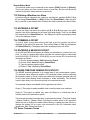
T3.05 Self Test
To check that port A/E is correctly configured as an input connect a machine to port B, configure as a
master ([Shift} followed by [B]) and connect port A to port C (Use a Tx-Rx Invert cable if required). The
machine on Port B may be then be controlled from either B or C on the SR-4. Note that when LED A is
illuminated Local will be displayed when C is selected.
CB Electronics
SR/MR Technical Manual
26 October 2012 SR-Tech 15
T4.00 MACHINE INTERFACE DETAILS
These notes are included for reference, they include some machine setup details and some SR Setup
details, if the machine is correctly identified by the SR then there should be no need to change the setup
unless the machine software has changed significantly.
T4.01 FOSTEX D-10
CHASE
The D-10 has no chase capability and must be used as a master only.
VIDEO SYNCS
The D-10 does not resolve to video syncs, it may only be used in systems with slaves that will
chase timecode.
The D-10 is not recommended for video applications, if used as a master to a video machine then
the lock will be +/- 1 frame.
MACHINE TYPE
DAT-1: Assemble record only audio + timecode, Returns A1, A2, A3 record ready at all times.
Record ready keys are not normally required. The SR & MR remotes check that either A1, A2 or A3
record ready enables are active as record enables for the D10.
EDIT-ON
The D-10 ignores the Edit-On command, A Record-On command must be sent to enter Record!
Enable Record-On instead of Edit-On command in the interface setup.
TIMECODE GENERATOR
The D-10 has no internal timecode generator, because of this it is recommended that great care
should be taken when formatting DAT's. The Timecode generator must be referenced to video and
the D-10 must be referenced to word clock derived from the same video syncs.
DEVICE ID
Returns the FOSTEX generic ID only
T4.02 FOSTEX D-20
D20
D20B
CB Electronics
SR/MR Technical Manual
26 October 2012 SR-Tech 16
T4.03 FOSTEX D-25
Record Enable
1) Record enables A1, A2, A3, or assemble
2) Via the RS-422 it is possible to record on individual tracks, to enable on the SR/MR Set
IFACE|General|Machine Type to 4= Dat2
RECORD TALLY BUG
The D-25 record tallies only appear on D1, D2 not on A1, A2, or A3.
Timer-1 Bug
Timer 1 position request reports timecode not timer.
Offset Command Bug
1) Offset commands cancel locates
Select-EE Status Bug
No Select-EE tally
Chase Command Bug
Does not support Chase until locked command
THIS MACHINE WILL NOT LOCK TO PULL-UP/DOWN CODE
VTR Emulation
000 FOSTEX
002 PCM-7050
004 BVU-800
001 PCM-7050
003 BVU-800
005 BVU-800
T4.04 FOSTEX D-30
RECORD MODES
1) Play & Record: A1 & A2 & A3 individually
2) Instant Start: No Record
3) Confidence Record: ASSEMBLE edit only!.
4) Sub ID Edit: A1, A2, & A3 individually available
RECORD COMMAND's
A1, A2 A3 only not D1 or D2
RECORD TALLIES
Remote A1/A2 record enable returns both A1/A2 and D1/D2 tally
Local A1/A2 record enable returns only D1/D2 tally
Remote D1/D2 record enable have no effect
Remote or Local A3 (Timecode) record enable returns A3 tally
Remote Assemble enable returns assemble tally
Local Assemble enable returns no tally (Insert flag Only)
TIMECODE STANDARD BUG
1) ID Data does not change with standard change unless he unit is powered down and up unless
new standard is the same as recorded on the tape.
SERIAL PORT STARTUP
Serial port disconnection and reconnection can cause the Fostex Serial software to lock out, if this
happens switch machine power off then on.
CB Electronics
SR/MR Technical Manual
26 October 2012 SR-Tech 17
T4.05 TASCAM DA-88 / Sony PCM-800
VARI-PLAY/CHASE
Not all versions of the DA-88 software support vari-play commands. If your software does not
operate correctly then DA-88's internal chase synchroniser must be used. To use the internal
chase synchroniser the master timecode or timecode output of the SR-4 must be taken to the
timecode input of the DA-88. VARI-PLAY commands issued from play intermittently cause the
transport to stop.
TRACK ENABLE BUG
Earley Software Front panel track enable switches do not update the P2 Serial port! When
Commands on the SR remote are disabled the record tallies on the remote will not reflect the
current status of the machine. On Later software this is corrected!
EDIT STATUS BUG
The Edit status flag is not cleared on the RS422 port if you drop out of record on the machine,
remote or due to lost lock. The Record tally operates correctly and is cleared.
UNLACED TALLY BUG
The DA-88 does not report its unlaced status when it unlaces due to timeout. To Lace the DA88
depress the stop key on the SR-4 before issuing a chase command.
LOCK TALLY BUG
1 The DA-88 Lock tally is removed when in record or edit. This can cause a problem with the Mute
output when dropping out of record.
2 The Lock Tally is removed if TC Generate is enabled
SY-88 SWITCH SETTINGS
Switch settings:S1 Rear Panel
#1 video 75R termination = down
#2 Must be DOWN for RS422 (Switch Power Off & ON after changing)
#3 Down = Rechase Enabled
#4 Rechase when error exceeds Down = 1 sec, Up= 2 sec
#5 Timecode Output timing Up = Digital Audio, Down= Analog Audio
#6 Midi TC Source Down = Tape, Up = Input
#7 Video Resolve: Up= Lock to Video, Down= Lock to TC
#8 Controller type: Up = Video Editor, Down= Can Send Chase Command
S3 SY-88 Nearest edge
#1 OFF Tascam ID
#2 OFF Tascam ID
#3 OFF Tascam ID
#4 ON Digital 1-8
#5 OFF Digital 1-8
#6 Shuttle Speed:- ON = 8*, OFF = 100*
#7 ON Track Arming enabled from 9-pin
#8 MIDI Output MMC & MTC: OFF = Output MTC, ON = No MTC Output (reverse to Tascam
Information!)
Version 4
Select TC display, Depress ^ and v together to enter setup
use the ^ and v keys to change a menu item, depress display to change menu.
1) Chase mode:- ........................................ChS. rEch
2) Remote Enable:-..................................... rent EnA
3) Device type:- ..........................................d. tASCAn
4) Track Arm On:- ...................................... trK.Arn.on
5) Track arm type:-.......................................tn. d 1-8
PCM-800 Word Clock Input
PCM-800(UC) 20001+, PCM-800(CE) 50001+
The Wordclock input is level sensitive and will not work correctly with the word clock outputs from the
PCM-7030 or PCM-7050 details from Sony APM95-049R 22nd Dec 1995
CB Electronics
SR/MR Technical Manual
26 October 2012 SR-Tech 18
PCM-800 SYSCON PCB change R9 from 100R to 10K and Remove R10. Then use an external 75
Ohm Terminator. Or use a W/C distribution Amp!
T4.06 TASCAM DA98 Sys Ver 1.0, Sync Ver 1.0 Current version 1.2 for both
TRACK ARM TALLY BUG (Fixed in Sys version 1.2, Sync Ver 1.2)
The response to the track-arm tally request is inaccurate and its use must be disabled:Version 1.0 Select Root | Iface | Record | Menu 48:- Track Ready Tallies .........................3= Stat
TRACK ARMING
Version 1.2 Track tallies are both accurate and valid.
OFFSET BUG (On Version 1.2)
This machine does not accept Negative offsets (>12:00:00:00) contact teac on www.teac.co.jp to
complain.
To Setup a DA98,
1) Press ESCAPE to display Select Menu Group.
2) Select Menu Group 6 9Pin(Emulation) using the cursor keys, then use ENTER key to select the
menu.
3) Set Tascam emulation as follows:Select Eml Dev using the cursor keys
Use the ENTER key to enable the adjust mode
Select TASCAM using the cursor keys.
Use the ENTER key to confirm the selection
4) Set the Track map as follows:Select Trk Map using the cursor keys
Use the ENTER key to enable the adjust mode
Select the display as below using the cursor keys:Track Mapping
Ana
Dig 1 2 3 4 5 6 7 8
Trk 1 2 3 4 5 6 7 8
Use the ENTER key to confirm the selection
5) Press Escape to return to Select Menu Group
6) Select Menu Group 3 McnID,Ofst/Tmod/Rmt using the cursor keys, then use the ENTER key to
select this menu.
7) Select Trk Arm using the cursor keys, then use the ENTER key to select this menu>
8) Use the cursor keys to select Remote Track Arming enable, then confirm with the ENTER key.
9) Select Ctrl Prt using cursor keys, then use the ENTER key to select this menu:10)
Use the cursor keys to select 9Pin, then confirm with the ENTER key.
11)
To use ABS/recorded timecode select Menu Group 5, ENTER, select Tape TC, ENTER,
select TC Track/ABS as required.
Locking to Word Clock
Menu 5 video resolve on:- use front panel switch to enable word clock.
CB Electronics
SR/MR Technical Manual
26 October 2012 SR-Tech 19
T4.07 Tascam DA-60
1) Does not like repeat locate commands, locate routine uses up o 2 seconds play into park. If a locate
to current position is sent the machine will wind back two seconds and relocate. Must feed master
timecode and use machine chase.
2) Track arming
Optimum Setup
Suggested setup:Menu 53: Chase Command type.................... 5=0
Menu 54: Start Advance ........................... 6= Frames
Menu 55: Park Offset * 5 Frms ...8= (To minimise play to park)
Menu 60: Acceptable Error .............................. 1=
Menu 64: Locate Speed............................ 4=VSLOW
Menu 62: Slew Command Type .............. 0= Vari-Play
Menu 65: Locate Type ...................... 0= Wind then Locate
DA-60 Mark II
Use Analog track arming
Chase type 5/0
Reports $b4 in digital tracks 1-8 when any track is armed
Track 3 (Timecode) will only work when tracks 1&2 are disabled
T4.08 Tascam MMR-8 Version 5.01
MMR-8 Setup
1) Depress the [Setup] key
2) Depress the [0] key to select 000 Control Mode
2) Depress [Trim] key and adjust jog wheel until the display shows Editor or Timecode Chase
3) Depress the [store] key
4) Depress the [setup] key to exit
Other Important settings:001: Frame Reference
002: Sample Reference
003: Timecode Type
400: Editor Device: *Tascam MMR-8
403: Editor Trk Arm: *Digital Audio
404: Editor Chase: *Timecode
990: Software Version
Connect the SR3/4 to the Editor 9 pin port on the rear of the MMR-8
Use [Shift] followed by [1] to display the Offset
Synchronisation
Software revision 4.2 includes the chase and set offset commands. Use chase type 0
It will also lock using chase type 5.
CB Electronics
SR/MR Technical Manual
26 October 2012 SR-Tech 20
T4.09 SONY PCM-3324S
TIMECODE
For accurate control it is recommended that the timecode output from the machine is connected to
the SR timecode input and that this is used to update the position when valid. ( Note: There is only
one timecode reader per SR system, and one per box in an MR System).
TIMER MODE
Timer Mode must be switched to timecode
VIDEO SYNC LOCK ENABLE
For synchroniser to operate correctly Enable Timecode sync play on timecode board
CHASE COMMAND BUG
The RS422 Chase command does not work, returns undefined command
OFFSET COMMAND BUG
The RS422 Offset command inoperative, returns undefined command
POSITION REPORT BUG
Some 3324S's do not report there position correctly via the RS422 port, this causes problems
when locking up. Typically the difference between the timecode and the time reported on the
RS422 port varies from 0 to 10 frames or more!
If you have this problem then get a copy of the Sony Technical Memo APM95-005 from your local
Sony service office. After this modification has been carried out the DABK-3322 9-pin interface
board must be installed in the middle slot of the right hand three slots. This is shown as slot 2 on
page 2-1 of the DABK-3322 manual.
LOCK STATUS BUG
The 3324 Reports Lock even in Vari-Play, or when the Play LED is flashing.
RECORD STATUS BUG
The 3324S does not report track 1-8 record status in the normal status data
TRACK ARM/E-E BUG
The 3324 will not drop out of Auto-E-E in play only stop
Tracks 1-8 will drop out of Edit when edit off is sent in stop after auto e-e command
Track arm commands upset the position reporting from the 3324
Rehearse/Auto Input bug
Once the auto input command is sent, there is no way of removing the auto input tally.
Sony Setup
Vari-Sync On/Off (Dip switch 4),
The optimum setting of this switch is 3324 software revision dependant! New software
seems to work with Vari-Sync OFF
Advance Record Off
TCGEN set to EXTERNAL
Timecode sync play ON (Timecode Board)
Timer mode = Timecode
CB Setup
Chase Type 3
Start up Delay 7
Wait for code 9
Software version numbers
1) MC software is displayed on power-up 3.02
2) Servo card, 3.01 + 3.02A
3) DABK-3322 Option board on rear 3.02A
External Word Clock
When running to external word clock Programable Play will not work, Root | IFace | Chase | Menu
62: Slew Command should be changed to 0= Vari-P, 2= Prog-P, or 3= V->PP cannot be used. As
the 3324 is no longer locking to the video frame edge
Internal Synchroniser Free Mode/Address Mode
The internal synchroniser may only be used in Free Mode when using external word clock. In this
CB Electronics
SR/MR Technical Manual
26 October 2012 SR-Tech 21
mode the synchroniser will lock and release to external wordclock.
T4.10 SONY BETACAM
VARIPLAY
To slave a Betacam machine variplay must be ENABLED
VARIPLAY RANGE
To slave a Betacam in both forward and reverse, menu 301 Variplay Range for Synchronization on
the Betacam should be set to -1.3 ~ +2.3. When shipped this menu cannot be selected, The
System Setup Menu Select switch (S106 on machine tested) on the SY-61A system board must be
on to allow access to this menu.
T4.11 Sony DVW-A500P
Digital Betacam
LOCATE
The A500 may be set in menu to Stop or Still at the end of a locate, this must be set to Still so that
you may see the picture after a locate or when a slave.
Menu 401 "After Cue -> Still"
EE
The A500 does not respond to Full-EE ON or Full-EE OFF commands. The EE Flag in the status is
not valid.
Machine ID
This may be set in maintenance mode to be different machines for different editors. Hold menu key
down so that customise menu is enabled. Jog to the end, then hold the play key down and jog to F16
D-Type Modi and enable. Exit and re-enable the SETUP-1 Menu. use the JOG and PLAY keys at the
end to access menu F-1T4.
Tracks 1..4 are Digital audio record
Track 49 or 50 are both cue
Track 51 is timecode
T4.12 Sony 7040 2.+
7040 Setup
Gen Out Regen NO
Sync Record Enable = ON
Other settings should be the same as the 7030
The machine ID of the 7040 may be changed on S302 which is an DIL 8 switch located at the rear left
of the unit as follows
S302-3
S302-4 Device Type
OFF OFF 7030
ON
OFF 7050
OFF ON
7040
ON
ON 7040
CB Electronics
SR/MR Technical Manual
26 October 2012 SR-Tech 22
T4.13a SONY PCM7030 5.1 Revision T110
PNO RECORD
Auto increment PNO numbers in Assemble ONLY
REHEARSE
If Root|Iface|Record|Menu 46: Command Reenforce is set to 2= Track Arm or 3= Both then
Rehearse will not operate correctly it will switch once per second between input and tape!
AUDIO RECORD ENABLE
Audio 1 & 2 Record enable on D1 or D2 only. Stereo record only.
SUB CODE RECORD ENABLE
To record in the SUB CODE enable A3
CHASE SWITCH
For the Chase Enable/Disable to work correctly on the RS422 remote select the following in the
7030 menu:RE-CHASE ON 1 * Chase mode function
CHASE AU PLAY * Selects playback audio timing
CHASE-S ON * Use Chase switch to turn chase ON, Stop Switch to turn OFF
May be causing problems with record drop out? solved by using:- Chase On/Off
Edit Off will cause the 7030 to drop out of CHASE if it is in record, but not if it is in PLAY!. The
solution is to send a PLAY command to drop out of Record! (Iface | Record | Menu 45, Record
Command 1= RECORD / PLAY, this unfortunately stops the machine from dropping out of input
monitor after a rehearse. 7030 revision 5.1 does not have this problem!
A consequence of this is that the Rehearse will not work correctly. If you need the Rehearse
function to work correctly then you must use the SR/MR synchroniser and select EDIT ON/OFF.
Note *= Factory Preset, != change from factory preset
SUGGESTED SETUP
Chase Type 0 or 4
Start Delay 5 frames
Park Offset 1 Second
Attempts 4
Acceptable error 1
Locate Speed 2= MED
Slew command 2= Prog Play
Record Command 1= Record / Play
Chase Edit On
For Wide Varispeed Operation Eg 4% Pull Up/Pull Down
Enable External Word Clock 'Sync Ext'
MAIN MENU
Sync err
Sync Pb
CB Electronics
Off
Disable
SR/MR Technical Manual
26 October 2012 SR-Tech 23
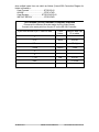
T4.13b Sony PCM7030/7040/7050
SR Menu 53
Chase Type
SR Menu 45 Record
Command Type
Sony PCM Menu
Limitations
0= Cmd
0= Edit On/Off
Chase-S on
Will drop out of Edit when receiving an
Edit Off Command
0= Cmd
1= Record/Play
Chase-S on
Rehearse Off will not Function
0= Cmd
0= Edit On/Off
Chase-S on/off
4= +
0= Edit On/Off
Not Used
Cannot take Sony PCM out of Chase
Mode
Longer to Lock
Must use Video Not Wordclock
T4.14 SONY VO-9800/VO-9850
VO-9800 TRACK ENABLE
Audio-1 is permanently enabled, because of this the unit will initialise with Record disabled. To
layback or record on Audio-1 use the serial setup to enable record commands to the machine.
VO-9850 TRACK ENABLE
The machine must be in EDIT (MODE SELECT SWITCH) for the EDIT commands to work.
CHASE
To slave this or any video machine ensure that the colour framing is turned OFF. The SR software
will send a COLOUR frame off command to the machine on entry to play. On exit from play the SR4 will send a "Set colour Framing to Switch" command.
TIMECODE
A timecode card must be fitted and the display selector must be set to TC in order for the locates to
operate correctly.
LOW BAND TAPES
When Audio-1, Audio-2 or VITC only are used for timecode we recommend that the machine is
modified to allow timecode track selection from the front panel. This allows the user to select Audio1, Audio-2, code-track, or an external VITC to LTC converter as the timecode source for the
internal timecode reader. This value is then updated by the tach if the timecode is not readable and
allows the machine to perform timecode locates.
CB Electronics
SR/MR Technical Manual
26 October 2012 SR-Tech 24
T4.15 STUDER TLS4000 Mk I
Local Control Unit
This must be disabled in order to use the RS422 remote!
RECORD TRACK ENABLES
Available for studer multi-track machines
The TLS Mk I programs the record enable for two channels with each command. There must be a
time delay between each command. The commands include the monitor setting and mute status.
The SR-4 will set each track between Record ready and Sync Replay, or Normal Replay dependant
on the setup configuration.
Bug: Reports last serial command not actual tallies.
DEVICE TYPE
Will always report as TLS Mk 1
SHUTTLE & JOG
Not yet implemented
1) Hardware Switch at Rear
A
B
X
X
X
X
2) Middle Switch
OFF 1
ON 2
3) Baud rate links at Front Right hand side:
Two Links as follows
1234567890
........X.
........X.
CB Electronics
SR/MR Technical Manual
26 October 2012 SR-Tech 25
T4.16 STUDER TLS4000 Mk II
Local Control Unit
This must be disabled in order to use the RS422 remote!
Communication
The SR-4 will talk to one TLS4000 synchroniser only on each output port, RS422 communications
using the native TLS format are used.
Record The TLS Mk II programs 4 channels with each command
DEVICE TYPE
Currently reports as TLS Mk 2
SHUTTLE & JOG
Not yet implemented
1) LEFT HAND SWITCH
1 =ON \
2= OFF > 38K4
3= OFF /
4= OFF \ EVEN PARITY, ONE STOP
5= ON /
6= ON \ RS422
7= OFF /
8= OFF
Both LED's OFF = NO COMMS
Left OFF, Right ON = OK
T4.17 STUDER D820
SHUTTLE & JOG
Not yet implemented
SETTINGS
The Internal Synchroniser must be selected (The Front Panel Lock key should operate)
RECORD TALLY BUG
Strange Track Record tallies are generated even when the machine is not in record if the machine
drops out of record due to loss of lock. A special routine has been written to compensate for this. If
the system locks up in stop with the record tally on then deselect the machine, and on the machine
enter play, record on then off. Then reselect the machine. Alternatively turn the D820 off then on.
LOCK ERROR BUG
The D820 sometimes outputs its lock error without subtracting the offset. A Machine power cycle
may cure this.
Internal Synchronise
Internal Synchroniser On
TC Lock Off
CB Electronics
SR/MR Technical Manual
26 October 2012 SR-Tech 26
T4.18 DAR SABRE
CABLE: The 9 pin cable must have the Rx & Tx inverted (Section T5.02)
Reverse Play Bug
The Sabre will not accept reverse play commands
Chase Command Bug
Chase Not implemented
Record enable
Only when in stop, ignores reenforcement commands if enabled in any other mode and then
stopped.
Menu, Full VTR Emulation/Emulation Timecode
VTR Emulation must be displayed on screen
DAR Soundstation Gold
Normal Mode
1) May not accept SR timecode
2) Does not issue Locates
3) Does not issue Record commands
4) No wind speed limits to work with non-linear video
VT Emulation
1) No Jog with Audio
2) Does not accept reverse play command
3) Front panel switched off, not possible to control both DAR and SR
4) No Machine ID , Auto Setup will not work, You will have to set all the parameters as follows:Chase Type ..................................................... 5=0
Record tracks .................................................... 8
5) Make sure that Video Lock is enabled on the DAR so that the Lock tally is returned.
T4.19 DAR OMR-8
The following commands are not implemented:1) Vari-play, Shuttle, Jog
2) Set Offset
The following tallies are not implemented:1) Local
2) Record tallies, if changed at the machine
3) Response to command request track ready status (43 30 02)
CHASE
Chase 0=Cmd must be used, offset must be set on the machine.
CB Electronics
SR/MR Technical Manual
26 October 2012 SR-Tech 27
T4.20 AKAI DR-8
ID Request always reports as a BVW-75 FILM machine, Now switchable to DR-8 or BVW-7T1
POSITION REQUEST: Use 0= LTC or 3= LTC+VITC, Do Not use 4= L+V+T!
TRACK ENABLES are invalid if changed during record. The serial port reports correctly but the tracks
are not enabled on the machine.
TRACK ENABLES are only possible when SYNC is enabled, track selection when the LTC input is
enabled requires that the DR-8 is chasing an external source of timecode (SYNC ON). To use this
machine as a stand alone recorder then the LTC input should be switched off.
TRACK ENABLE TALLIES are not updated to the serial port unless the SYNC is enabled.
The SET OFFSET command is not implemented on the serial port.
The CHASE command is not implemented on the serial port.
TO ENABLE/DISABLE THE LTC
1) Sub Menu, Select SYNC, display should read SMPTE-LTC, if not use inner jog wheel
2) Press STORE/ENTER, display should read LTC OFF, if not rotate outer jog wheel. Press
STORE/ENTER to confirm selection.
To ENABLE and SELECT the MODE off the SERIAL port
1) Sub Menu, Select SYNC, display should read RS422-MC, if not use inner jog wheel
2) Press STORE/ENTER, display should read FULL SLAVE, if not rotate outer jog wheel. Press
STORE/ENTER to confirm selection.
3) Display should now show EBU 25F or desired frame standard, if not use outer jog wheel. Press
STORE/ENTER to confirm selection
The SYNC key may now be used to Enable/Disable the communications.
TRACK MAPPING
To enable the record track selects
1) SUB MENU, SET UP The display should read RS422, if not use the inner jog wheel to select
RS422.
2) Press STORE/ENTER, use the inner jog wheel until the display shows TRACK MAP
3) Press STORE/ENTER, use the inner jog to display DIG->ON if the display shows DIG->OFF use
the outer jog wheel to position the cursor under OFF, then use the inner jog wheel to change to ON.
4) Press STORE/ENTER to confirm selection.
CB Electronics
SR/MR Technical Manual
26 October 2012 SR-Tech 28
T4.21 Akai DD-8 V1.01
COMMS BUG
The Akai will not answer comms for several frames when starting and dropping in and out of record
STATIONARY CODE
Stationary Code causes, the unit to occasionally drop out of Chase
DD8 RS422 SETUP
1) Select RS422 Menu page
SYSTEM : F6 MORE : F2 REMOTE : F2 RS422
2) Select FULL SLAVE
MODE : Set Mode using DATA+/- to FULL SLAVE
3) Select RS422 ID
F2 ID : Set RS422 ID using DATA+/- to DD8
4) Set Edit Delay
F3 DELAY : Set Edit Delay to 2 frames(minimum) using DATA+/5) Set Track Arm
F4 TRACK ASSIGN : Set A1..A4 OFF and DIGI ON using F1..F5 and DATA+/- keys
6) F6 EXIT : SYSTEM Then chose to save with Project or in Flash Rom
7) Set track Mode
RECORD : F2 Setup : F5 Punch : Punch Mode :
using DATA +/- Set to TRACK KEYS
DD8 Track arm Indication
Select RECORD on Keys below the Track Keys, Enable then Disable 9/Sync to enable 9-pin
control
DD8 RS422 Remote Enable
To use the Remote enable you must set 'EXT TC' in SETUP/SYNC page to 'NONE' - otherwise this
switch is used as the timecode chase on/off switch.
Enable 9/SYNC
You should now have transport control and track arm.
To CHASE using the DD8 Synchroniser
DD8
1) SYSTEM
2) F2 SYNC:- Ext timecode source : select type using DATA+/3) F6 EXIT : SYSTEM Then chose to save with Project or in Flash Rom
SR
Setup | ROOT | IFace | Chase Type 0= CMD
To CHASE using the SR Synchroniser
DD8
1) SYSTEM
2) F2 SYNC:- Ext timecode source : select NONE using DATA+/3) F6 EXIT : SYSTEM Then chose to save with Project or in Flash Rom
SR
1) Setup | ROOT | IFace | Chase Type 5= CMD
2) Start up Delay = 1
3) Park Offset * 5 frms = 2
4) Attempts for ZERO error = 2
5) Acceptable Error = 2
6) Locate Speed = 0 TLESS
7) Slew Command Type = 2 Prog Play
8) Play+Lock before Variplay = 1
If the SR loses control of the DD8 toggle the 9/SYNC key on the DD8
Version 1.05 with GPIO card
1) Serial track arming and tallies do not work!
2) The DD8 loses communication for a frame after receiving the chase command
Tip: To check the directory status use DISC/UTILITY/ENTER+F1
CB Electronics
SR/MR Technical Manual
26 October 2012 SR-Tech 29
T4.22 AKAI DD1500 (Version 2.00 a/a)
To Enable the VTR CONTROL connector as a INPUT use the following key sequence:SHIFT + EXT M/C
This displays the RS422 Machine Control Setup
^+v
Select the RS422 Mode
DATA ENTRY/NUDGE +
Until FULL SLAVE is displayed
^ or v
Select the RS422 ID
DATA ENTRY/NUDGE +
Until DD1500 is displayed
F1 TRACK ASSIGN
To access the RS422 TRACK ASSIGNMENT Menu
< or > Select D1-16
^ or v Select D1-16 ON to enable remote track enables
Track Selects
To enable external control of the track selects use the EXT M/C switch, external control is enabled
when the LED is illuminated.
ID Request always reports as a BVW-75 FILM machine, Now switchable to DD-1500 or BVW-75
Note: To improve Record in/out response time connect the Rec-On and Rec-Off GPI outputs to the
corrisponding GPI inputs on the DD-1500.
POSITION REQUEST: Use 0= LTC or 3= LTC+VITC, Do Not use 4= L+V+T!
CHASE BUG
The DD1500 will accept the RS422 CHASE command but unfortunately it does not exit when a
STOP command is sent. This means that there is no way of exiting chase except by using the
EXT.TIME switch on the DD1500. When the Chase (EXT.TIME) is enabled via the RS422 the
DD1500 behaves differently in that when the external code stops or changes direction the DD1500
stops chasing.
RECORD BUG
If you use a RECORD ABORT (SHIFT RECORD) on the DL1500, the next time you enable a track
via the 9 pin remote the system will enter RECORD!!!!.
TRACK ARM BUG
When in play the DD1500 will only accept the first track arm command. All subsequent track
arming commands are ignored until you STOP the DD1500.
T4.23 SSL SCREENSOUND
1) 'SETUP' 'SERIAL' Enable Sony Slave STD Motion Record
2) 'NETWORK' 'MACHINES' OFF SIO Linked as controller
3) Use RX/TX invert cable
CB Electronics
SR/MR Technical Manual
26 October 2012 SR-Tech 30
T4.24 SSL AXIOM
The Axiom serial interfaces have four different modes of operation as follows:-
1) Grey Master
All four serial ports may be grey masters, The Axiom acts as master and synchronises the attached
machine to the Axiom Timeline. A grey master is always slaved to the Axiom timeline. This mode
suits fast responsive machines. A stop command from play, reverse play or wind is translated to a
'LOCATE TO HERE' command, when slow (film) machines receive this command they slow to a
stop, reverse direction and locate to 'HERE'.
2) Green Master
Only one port may be either a Sony Slave, Green Master or Red Master. The Axiom acts as
master in play, but the Axiom timeline follows the Green Master position in wind. A Green Master is
slaved to the Axiom timeline in play but acts as master to the Axiom timeline in wind. A stop from
wind waits until the machine is stopped, then the timeline and all machines locate to this position.
Stop commands from play or reverse play are still translated to 'LOCATE TO HERE'
3) Red Master
Only one port may be either a Sony Slave, Green Master or Red Master. The Axiom commands
the machine, the Axiom timeline follows the Red Master machine position in all modes. Stop from
play or reverse play are still translated to 'LOCATE TO HERE'
The optimum serial setup for both Grey Master and Red Master is as follows:Fixed adaptive lockup = 12 in PAL and 14 in NTSC
RECORD
* The Axiom record switch acts as a RECORD MODE, this may be enabled at any time, Every time
a command is issued a EDIT OFF command followed by an EDIT-PRESET command is sent.
* If the controlled device is in PLAY and the RECORD MODE is enabled then provided that at least
one channel is armed a series of EDIT ON commands will be sent until the device is in record.
* If the controlled device is put into record by another remote then the AXIOM will automatically take
it out of record if the AXIOM is not in RECORD MODE.
* If the controlled device is taken out of record by another remote then the AXIOM will automatically
put it into record if the RECORD MODE is enabled.
* The Edit On commands will start as soon as a play tally is present and will not wait for a lock tally or
even lock with the Axiom
PLAY
The Play tally will stop flashing when the master is in frame lock with the Axiom, the Axiom will not
wait for a Servo Lock tally.
4) Sony Slave
The Axiom timeline is controlled by an external controller only one port may be either a Sony Slave,
Green Master or Red Master. The Axiom timeline is controlled in the same way as any machine by
selecting Sony Slave mode. The optimum setup for controlling the Axiom from a CB product is as
follows:1) LOCATE ONLY, Non linear audio a locate is always faster than Wind.
2) Chase type '5'
3) Locate speed: Very Fast (Locate 0)
4) Record Ready Off, the Sony command "EDIT PRESET SENSE" causes the AXIOM to
lock out, to avoid this Edit Preset and Edit preset Sense commands must be turned off.
The lock after reverse play or reverse wind is slower than the lock after play or forward wind. The
Axiom appears to take longer to start moving after reversing.
Note: The 9 pin cable must have the Rx & Tx inverted (See Section T5.02)
Note 1:
In all modes the Axiom timeline is either master or follows the Sony Slave, Red Master or Green
master machine. The remaining three Grey master machines are slaved to the Axiom timeline and
will therefore follow in all modes.
CB Electronics
SR/MR Technical Manual
26 October 2012 SR-Tech 31
T4.25a AVID Audiovision
The SR-3 may be used as a multi-machine controller with the Avid, by using the timecode reader the
Avid may also be slaved to an external source of timecode.
1) AVID Cables:The Avid machine control cable (Male 'D') will work correctly with SR-4 only in Port-A if the Links
are Horizontal (SR-3) position). This cable may be used in ALL modes.
The Avid Emulation cable (Female 'D') will work correctly with the SR-4 when connected to any
port, If connected to port A then the links must be vertical (SR-4). This cable will only work correctly
in machine emulation mode.
2) Ensure that all parts of the system are locked to video syncs, (Avid, Micro-Lynx, CB MC-1 if used,
SR-3)
3) Connect the Avid super clock input to a suitable source of 256 * Word Clock for example the DigiDesign Video Slave Driver or the Rosendahl WIF.
If the Micro-Lynx is used then the clock rate must be manually as follows:1) SETUP : 2) ACG
3) Use + or - keys to select correct frequency
4) SETUP The following preferences may help: Park Ahead On
AVID Transport Control Modes:LOCAL
No Interaction, The Avid Timecode output may be used as a master to the system, connect to
SR/MR timecode input and select READER as Master.
AVID as MASTER to SR-3
MASTER
The SR-3 master machine will be controlled by the Avid. In play the Avid will lock to the SR-3
Master machine.
SLAVE
The Avid will follow the SR-3 master machine.
In this mode the SR-3 should be set as follows
Setup | Root | Unit | Generic |Menu 31 Serial A type 1=Input
The A key will act as a Local/Remote switch for the system
Use Shift followed by B, C, D to select the Master
4.25b AVID as SLAVE to SR-3/4
REMOTE
Used in the Deck emulation mode. The SR-3/SR-4 can control the Audiovision. The
Audiovision sends a NTSC VO9850 ident unless changed using set devicetypedata
commands as below. When using the Avid in Local, positional information on the emulation
port is only updated in stop!
Notes on PCI BUS Machine
1) Track arming only active when in stop
Setting the Avid ID number, the SR-4 will configure correctly if you select the 3324 id as follows, use
getprop instead of set to check current settings:Windows
Console
Setting a PAL ID
CB Electronics
SR/MR Technical Manual
26 October 2012 SR-Tech 32
set devicetypedata1 D1
set devicetypedata2 A8
Setting a NTSC ID
set devicetypedata1 D0
set devicetypedata2 A8
Park ahead used by remote mode
set slavedelay 80
set parkframes 85
set parkahead true
set VTRtriggerdelay 1.0 (Was 2.0)
BUG: Avid reports that the Video is always record armed
T4.26 AVID News Cutter
1) This is a DVW digital video workstation, designed to work as a stand alone system, it does not
work with any other equipment. Although it can control an external machine for play in it cannot
synchronise to an external RS422 or timecode.
2) There is no video emulation mode.
3) There is no timecode output.
4) There is no possibility of putting an external video machine into record.
The only way of getting program out of the system is to put the AVID into play and putting a video
machine into CRASH RECORD using the internal timecode generator as the timecode source.
T4.27 CB BS-1/MC-1
TRACK ARMING (Available on MC-1 Only)
A1..A4, Video -> Port B
D1..D16, MC-1 Parallel track arm outputs 1..16
CHASE SETUP
Chase Type ...........................................................5= 0
Start up delay......................................4= (Dependant on PACCN)
Park Offset * 5 Frms .............................................. 0=
Acceptable Error................................................ 1= Frms
Locate Speed ..................................2= MED (Dependant on ACCN)
Slew Command Type..................................... 1= Vari-Play
Wait for Code to Stabilise ...................................... 4=
Chase Locate ...............................................1= Locate Only
Serial Position Request............. 1= Start of frame (Old MC-1 Software)
CB Electronics
SR/MR Technical Manual
26 October 2012 SR-Tech 33
T4.28 Doremi V1 Version 1.99z
1) Must have correct Video reference input selected to report Servo Lock
2) Offset Cmd Bug:- A Sony Offset command sets the timecode output value.
3) Ensure that Menu 03 is not selected to "Chase Serial TC", in this mode the RS422 port is an
Output.
4) No Still Tally.
5) Erratic Shuttle performance, to improve use enhanced shuttle mode in option menu 27.
V-1 ID Setup
1) Depress OPTION & MENU together
Select the Option Menu 19 "Emulate" using the ^ & v keys
Use the -- and ++ keys to select V1 emulation
Exit using the Menu key.
2) Use Option Menu 04 "Save Yes" to save any new defaults if necessary.
Note: If MENU 34:- Enable Auto-in When NOT Play is enabled the Record LED on the Doremi will
illuminate when in Stop.
The MR/SR provides 6 commands that enable the user to access
the V-1 Segment commands:note: only available when the SR-4 displays Doremi as the machine type (see 4 above).
1) Select Segment ................ [Macro 181] or [Recall] followed by [ID >]
Enter the segment number followed by [Select Segment] to locate the start of the segment
This sets Doremi Option Menu 8!
2) Play Segment from Start ......................... [Macro 182]
This command will only operate if within the selected segment (Goto Segment) or the segment
mode is off.
3) Define Segment.................[Macro 183] or [Store] followed by [ID >]
Define the In and Out points on the SR then enter the desired Segment number followed by the
Define Segment command.
4) Select Next Segment .....................................[ID >]
eg, 4->5, 5->6, 6->7....255->256
5) Select Previous Segment..............................[ID <]
eg. 7->6, 6->5, 5->4...1->0
6) Clear Segment Mode ........... [Clear] followed by 1) Goto Segment
This will Locate the start of the Recording
The User display will show the Segment number as a PNO Number. Tape End will be displayed if at
start or end of segment.
CB Electronics
SR/MR Technical Manual
26 October 2012 SR-Tech 34
T4.29 Fairlight MFX-3
BUGS
1) Reports timecode standard as 24 FPS
Select Root | iface | General | Menu 72: Timecode Standard
1= Use System
2) Does not accept CHASE or SET OFFSET commands
Chase Setup
Chase Type = 5= -+ Current MFX software
Chase type = 4= + Older MFX Software
Park offset = 2 10 frames
Start Delay = 4
Slew Command Type 0=Variplay (1=Shuttle on very old software)
The Farlight has a configuration file
Check file 'TCS_TFG' look for line '@ setenv sony-timeout=??'
T4.30 Audio Kinetics ES-1.11/1.12
The SR-4 cannot improve the basic operation of the ES 1.11, It is essential to read the AK operation
manual and parameter setup notes in order to optimise the AK 1.11.
a) Only one ES 1.11 may be connected to each serial port on the SR-4
b) Interface Cable
SR-4ES 1.11
2
3
4
7
8
4
1
8
3
2
c) ES 1.11 Setup:1) Disable BUS
2) Set timeline reference as video: MENU SYSTEM MASTR Mas A
3) Set ES BUS address as 001: MENU SYSTEM ESbus
4) Set Mode to External: MODE mode<-Ext
5) Select user preferences as required, Play to park on/off, Record enable....
6) It may ne necssary to set MACH|PROG| 1014 (NoWild) to $FF
7) Enable Bus
d) SR4 Setup
1) Select Serial port A,B,C, or D
2) Select serial protocol "Setup" Root Menu, "2"= IFACE, "3"= Type "5"= AK
Bugs
a) The ES 1.11 will only report difference when in play mode
b) Offset commands cause the ES 1.11 display to flash
Emulation Mode
The AK1.11 may also be used in emulation mode
In Emulation mode the Local Setup menu LOCK should be set to Auto or Phase
1) Chase type 4
CB Electronics
SR/MR Technical Manual
26 October 2012 SR-Tech 35
T4.30 Audio Kinetics ES-1.11/1.12 DEBUG MODE
A debug display is available as follows:1) LOCAL | Option | Parameter Protrction = Off
2) MACH | PROG | Parameter 1040 (testit) set to 53
3) LOAD
4) The debug display is enabled using the Mode Key and is changed using the Menu Key
System Position System Speed Difference
Machine Position Machine Speed VLTr25 TLSVC Last Cmd
System Position: t= timeline, c=chase, r= real Master
Machine Position: l= ltc, t= tach
VLTr25: V= VITC L=LTC T=Tach r=Record Enable 25= Standard
TLSVC: T= Timeline, L= Lock Active, S= Goto Active,
V= Fast Slew v=Slow Slew l= Servo Released p= vari play
C= Chase
The Menu key selects an alternative Display for the top line
TMS TMP 0f 06ts 10000000
TMS
TMP
41= Stop, 42= Variplay, 43= Play, 4c = Record, 61= FWD, 62= RWD
18= Chase, 44= Step(jog), 46= Shuttle, 4e= Search(Goto), 51= Lock, 53= LPRS, 5a=
Calibrate
3rd digit 0= Trying, 1= Successful, 3= Failed
Logical machine commands:
00 Null
10 Lifter Normal
01 Play
11 Varispeed On
02 Stop
12 Varispeed Off
03 Crawl Stop
13 Pause
04 Record
14 Edit
05 Unrecord
15 Servo
06 Crawl Rvs
16 Rec Preset
07 Crawl fwd
17 Locate
08 Rvs Play
18 Step +
09 FFWD
19 Step 0a FRVS
1a Un-Rehearse
0b Toggle Mode
1b Sync Play
0c Rehearse
1c Init
0d Lace
1d Rehearse mode Toggle
0e Unlace
0f Lifter Defeat
CB Electronics
SR/MR Technical Manual
26 October 2012 SR-Tech 36
T4.31 AUGAN 2.96/77S
Working with AES/WORDCLOCK
By supplying resolved Video syncs and Wordclock the Augan may be operated in RS422 device
remote provided that it is switches to Gen-Lock Mode.
1) Switch first to AES input and then to Video clock, the display should then indicate GL under the
sample rate.
2) Check Parameter 40 (Digital Audio Sync Source),
On the Sync Page
1) F5 sync options: F6 External clock: Sync ON, this selects video reference to the timeline.
2) F1 Mode: device (This also inverts the inputs so that no TX-RX Invert cable is required)
4) F2 VI Type: V1
The SYNC key is a remote enable switch (The Local/Remote Tally is not implemented by the Augan)
AUGAN OFFSET BUG
Older Software
When an internal offset is set on the Augan the RS422 position in Stop will be different from the
position in Play. To cure reset the offset to zero. (Now corrected)
Current Software (OS2.96/71S..)
If an internal offset is set, the position displayed on the SR/MR and on the Augan will be different.
The offset is used to calculate the Augan displayed position, the offset is not used on the serial
port.
1) Audio output in Jog and Variplay
The audio will be muted if a speed of more than +5% is requested ($4A), when in forward the audio
will be un-muted when the speed is returned to play speed, In reverse once muted the audio is
never un-muted, also the jog/varispeed is not correct in this mode.
CHASE SETUP
Chase Type ............................................................ 5=
Start up delay.......................................................... 5=
Park Offset * 5 Frms .............................................. 0=
Play before variplay ................................................ 0=
Acceptable Error................................................ 1= Frms
Locate Speed ...................................................0= TLESS
Slew Command Type..................................... 1= Shuttle !!
Wait for Code to Stabilise ...................................... 2=
Chase Locate ...............................................1= Locate Only
Max slew speed....................................................... 6
CB Electronics
SR/MR Technical Manual
26 October 2012 SR-Tech 37
T4.32 VPR-3 Version 7.3 PAL with Adrienne Interface (BVH-2K)
Suggested setup
Chase Type ...........................................................5= 0
Start up delay......................................7= (Dependant on PACCN)
Park Offset * 5 Frms .............................................. 5=
Attempts for ZERO Error.................................... 2= Trys
Acceptable Error................................................ 1= Frms
Locate Speed ..................................2= MED (Dependant on ACCN)
Slew Command Type..................................... 2= Vari-Play
Wait for Code to Stabilise ...................................... 4=
Chase Locate ...............................................1= Locate Only
Sync Correction................................................ 5= NONE
T4.33 TimeLine Lynx
Timecode
To use as a MASTER it is recommended that the machine timecode output is connected to the
SR/MR timecode input. When using used as a Slave there is no problem. (Note: There is only one
timecode input per SR system and one per box in a MR system.)
Lynx Setup
To enter the Lynx I setup menu hold the SET UP key depressed for approx 6 seconds, repeat to leave
the setup menu.
To enter the Lynx II setup menu hold the Blue key on the left depressed and depress the [SET UP]
key, repeat to leave the setup menu.
The MENU key is used to change the menu section, the FORW and BACK are used to select the
item to be changed. The v, ^ and CLR keys are used to adjust the selected item.
Select the following:Editor 0
Address 1
Lynx Local/Remote
The Tran Mode switch on the Lynx is used as a local-remote switch.
SR/MR Lynx Protocol Select
Select the correct protocol on the SR/MR:
Setup | Root | Iface| Type | Menu 78: Select protocol 4= Lynx
If 4= Lynx does not appear on the select protocol menu then this protocol is not fitted to your system,
contact your agent or CB Electronics to purchase the protocol upgrade.
Subframe Offsets
To set sub-frame offsets, enter the required sub frame offset followed by Shift followed by Store,
Followed by Chase/Offset, use Recall followed by Shift followed by Chase/Offset to see the
current sub-frame offset.
To check with Film Module: Link pin 17 to pin 33 and pin 16 to pin 32
CB Electronics
SR/MR Technical Manual
26 October 2012 SR-Tech 38
T4.34 FED Audio Solution II
This 4 track optical disc recorder can emulate a BVW40. The Sony P2 control input is on COM2 and
requires a special cable. A1..A4 are used as the track enables.
COM2 is RS232, for long cable runs a RS422 to RS232 should be used, positioned next to the Audio
Solution.
Cable details without RS422 to RS232 converter
SR-4
SR-4 FED COM-2
Tx Data 2
3
Rx Data 8
2
Ground 4
5
T4.35 Nagra T
The connection to the Nagra T is made via the Nagra RS422 Remote Control interface TA-RSA We
have tested the unit with software version ???? fitted to the TA-RSA interface.
RS422 Connection to Centre Connector- Remote C
The Nagra ID can be set to Nagra T using the Status Key to select the Menu, The + and - keys to step
through the menu and the Mod key to change the parameter. Select T-Audio
Menu 54 Start Advance ......................................... 2=
Menu 55 Park Offset * 5 frms ................................ 5=
Track Arming = A1 and A2
BUG The Nagra Lock tally is only present in Insert Mode?
When switched to Insert Mode the Replay Head changes, Tracks should be enabled in stop to
avoid losing lock.
T4.36 Sony DNW-A75/A100 SX Digital Video Hybrid
These machine use two different protocols one for the Tape and one for the Disk.
1) Program a key to Macro 163 or use Menu 78 (Root/Iface/Type) to enable/disable the special
protocol.
Bugs
1) In Disk mode the machine will not accept variplay commands greater than +/- 1* play speed.
CB Electronics
SR/MR Technical Manual
26 October 2012 SR-Tech 39
T4.37 FED V-MOD 100
SR-4 SETUP
When selected to 422DEV in the MASTER menu the V-Mod will answer with a BVW-40 ID, to change
this select Odectics as described bellow. If this is not possible the following changes should be made
to the standard BVW-40 setup:IFACE-CHASE
Menu 53 Chase command type............................5= 0
Menu 64 Locate Speed.................................. 0= Tapeless
IFACE-GENERAL
Menu 71 Pause/Stop Command .......................1= Stop
RECORD
The V-Mod will only accept crash record commands
TIMECODE
If the V-MOD does not have a timecode reader it will not record timecode with video. The best way to
set timecode on the V-MOD is to record a video with burnt in timecode or with a slate mark. The VMOD may then be set to this timecode after the video is recorded.
To record with serial timecode, select 422CON in the MASTER menu, connect to the playback
machine via RS422. Then depress Record ([REC] and [>]) on the V-Mod, The V-Mod will start the
playback machine and record audio, video and timecode.
BUG Timecode Standard
When set to Odetics protocol the V-Mod reports an IDENT of D8 01 this indicates that it is an
NTSC machine with SMPTE 30 timecode. When set to RS422 protocol the V-Mod reports an Ident
of 11 21 (BVW-40 PAL)
V-MOD SETUP
To Enter Setup
1) Depress LOCK & REC simultaneously
Enable the RS-422 on the V-MOD from Setup
2) Use the < and > to select the MASTER menu
3) Depress the Enter(LOCK) key to select the master menu
4) Use the + and - to select MASTER: Odectics (This sets the ID as V-Mod instead of BVW-40)
5) Depress the Enter(LOCK) key to return to MASTER menu
To Select External Video Sync from Setup
2) Use the < and > to select the VIDEO menu
3) Depress the Enter(LOCK) key to select the video menu
2) Use the < and > to select the VIDEO SYNC menu
4) Use the + and - to select VIDEO SYNC:COMP
5) Depress the Enter(LOCK) key to return to MASTER menu
To Preset the Timecode Number from Setup
2) Use the < and > to select the Timecode menu
3) Depress the Enter(LOCK) key to select the master menu
4) Use the < and > to select the Timecode digit to change
4) Use the + and - to select change the digit
5) Depress the Enter(LOCK) key to return to MASTER menu
CB Electronics
SR/MR Technical Manual
26 October 2012 SR-Tech 40
T4.38 Publison CP+
1) This DAW has no emulation mode and can only be used as a master to the SR-3
2) The 9 pin connections are non-standard
Publison
SR-3
Female
Male
1
2
2
7
3
3
4
8
5
4
6-9
7-8
T4.39 BTS DCR 500
This machine has two analog and four digital tracks, the digital tracks may be accessed as normal
(D1..D4), A1 and A2 will access D1 and D2
There are no tallies from digital tracks 3 and 4!
T4.40 STUDER V-8 Software 2.0 10/30/98
1) Depress 'UTILITY' repeatedly until "2 ONLINE SOURCE:" is displayed.
2) select using ^ or v until "2 ONLINE SOURCE: RS-422"
3) Depress 'UTILITY' and using ^ or v select "3 RS-422 Track Arm: On"
4) Depress 'UTILITY' and using ^ or v select "4 RS-422 Mapping: 1-2"
5) Enable the 'ONLINE' key
Record Tally Bug
No Record tallies! select record tallies NV on SR-4
Ident
Same Ident as BVH-2180 ($111C), this is good for us or we can supply an unused ident, I suggest
for use with OLD Editors you allow the user to switch between two idents, one unique and one
BVU950 or similar.
Comms bug
The RS422 port loses communication when ONLINE is off.
Offset Bug
The V-8 accept's a chase command but does not accept the Sony SET OFFSET command.
The V-8 will accept a Chase command or may be controlled by the SR-4 synchroniser, to use with
offsets the SR-4 synchroniser must be used with the current V-8 software.
Multi-machine Record Enable
The V-8 will only record as an 8 track on the current software (2.3).
Note; The V-8 will report record inhibit if the first tape is record inhibited.
Typical Internal sync settings
43 Chase type 3=
44 Start up delay 9=
45 Park offset * 5 frames 5=
CB Electronics
SR/MR Technical Manual
26 October 2012 SR-Tech 41
T4.41 Diva
Connections
Diva
SR-4
1
2
11
12
6,7
7
3
2
8
4
Emulates a BVW60 NTSC only, set to use System Standard with SR/MR systems
Current Problems
1) No Status Replys!
2) Locates not frame accurate in PAL (Frame accurate in SMPTE)
3) Does not accept Shuttle Commands
4) All commands other than STOP or JOG ignored when in PLAY
T4.42 Otari Radar-1 revision 1.46
Record Tally BUG
The Record tallies are offset by 8 tracks ie. Track 1 reports as track 9 etc.
Record/Edit On
Use Record and Play instead of EditOn and EditOff this will enable additional tracks to be dropped
in and out of record.
Track Arming
Unlike a Video machines tracks that have not previously been in record may be armed whist the
machine is in record and then may be dropped into record using a RECORD (Not Edit On)
command. Tracks that have previously been in record will go back into record immediately when
record armed.
Timecode Standard Bug
The Radar does not report the current timecode standard correctly, it will always report a timecode
standard of 30 NON DROP, it never reports EBU or Drop
Machine ID
Auto setup not possible because there is no unique machine ID
This machine reports as a BVU950 and should be set up as follows:Menu Function
42 Record tracks 4=24
43 Analog & Video 0=disable
46 Command Reenforce 2= Record (Until bug fixed)
48 Track Ready tallies 4= NV (Not Valid)
53 Chase command type = 5
54 Start up delay =2
55 Park Offset = 2 (10 Frames)
64 Locate speed = 0 (Tapeless)
56 Wait for Stable code = 2 (4 frames)
69 Machine type = 2 (ATR)
CB Electronics
SR/MR Technical Manual
26 October 2012 SR-Tech 42
T4.43a SSL G Series Computer (4K/5K)
1) Connections
1) Connect S29 on RM-6 Hub to 'Multitrack' under patch on SSL Console (25 'D' Male - 25 'D'
Female).
2) Connect Timecode out from RM-6 Hub to Master Timecode input on SSL (S113).
3) Connect S88 26 way ribbon cable (Maximum Length 2 meters) between SSL computer '78'
Card Port 2 and RM-6 Hub
2) SSL Setup
1) Type SSL Execute, the keyboard prompt should disappear, type the access code
BERNOULLI, this will not be displayed but the keyboard prompt should re-appear
2) Type Setup Execute and "Do you want to see more" should be displayed
3) Type # and set the following
Synchroniser type : 3
Master Transport Selector : YES
4) End End
5) Setup Execute
6) SSL Display's "Do you want to see more?" type "Y" to enter Engineer menu page.
7) S for Session and set "Using VITC" to YES this will enable the SSL to read stationary
timecode.
8) End, End
9) SSL Display's "Do you want to see more?" type "M" to enter Maintenance menu page.
10) Type "T" to select tape machine.
11) Select a spare tape machine position and type "Delete", answer Y
12) Type in name (EG. SR-24 25FPS) followed by "Execute" and enter details as follows:The Tach and Direction parameters will be constant as follows:Forward direction sense (L/H) : HIGH
Multiple Play speeds : NO
Pulses/Second at std speed:
25 fps EBU timecode, 5 pulses per second
30 fps SMPTE timecode, 6 pulses per second
Target Window : 0.0
Orop Out Command Type : 1
Drop In Command Type : 1
Time for Startup : 1.20
Time to be sure tape stopped : 1.10
The other auto-locate parameters will depend on the machine to be controlled
13) End
14) Type the "SYNC" key to enter Sync Menu Page
15) Type the "Setup" key to enter machine setup page and enter your machine name and select
the Menu No.
16) End
17) Type I to select the interface menu
Z8 interface No. : 2
18) End
19) Type the "SYNC" key to select the synchroniser options menu and set
Maximum number of masters : 5
Offsets may be read from synchronizer : YES
Single Machine Mode : NO
Timecode Generation : YES/NO Dependant on Machine
20) End End
CB Electronics
SR/MR Technical Manual
26 October 2012 SR-Tech 43
T4.43b SSL G Series Computer (4K/5K)
3) SSL Display
1) Use the Large/Small key, or use sync execute to view the machine page
2) The Down cursor key switches between Position & Time to Sync
3) The Left or Right Cursor keys switch between Mark & Offset
4) SSL Commands
1) AM{Execute} Sets Port-A as the Master
2) SYNC ON Enable synchroniser
3) Offsets:- use A at 00:00:00:00, B at 01:00:00:00
4) Locate C goto 00:00:00:00 Execute
5) ABC Setup Execute :- Toggle machine selection machines ABC
6) Sub frame offsets :- B* 00 Execute
7) Request Subframe offset :- B*? Execute
T4.44 Sony BVU-800 (Using timecode from an audio track)
The BVU-800 was the first timecode U-Matic, some early versions (I have found them in the USA,
Germany and Russia) either have no timecode card fitted or have only a timecode amplifier fitted with
no connection to the RS422 port. This technique may also be used when the timecode is not recorded
on the timecode track.
If this is the case then the timecode reader on the SR/MR may be used to read the timecode as
follows:1) Select Root | Unit | Code | Menu 27 TC Reader -> Port and select the port to which the
machine is selected
2) Select the BVU800
3) Select Root | IFACE | General Menu 70 Position
4) Enable 4= L+V+T (Request LTC, Video, and Tach)
T4.45 Ampex DCT-700
Sony Protocol
1) Reports Servo locked in all modes
Servo lock flag removed during transition between edit and playback modes
Servo lock flag removed during transition between Vari-Play and locked play
Ampex Protocol
T4.46 Sony PCM-3402
1) Start Delay = 13 Frames
2) Internal synchroniser is slow, and does not read stationary code
Menu 53 Chase type 3= Menu 54 Start up delay 9=
3) Digital Tracks 1 & 2, Analog tracks 1 & 2 (49 & 50) also arm Aux1 and Aux2
CB Electronics
SR/MR Technical Manual
26 October 2012 SR-Tech 44
T4.48 Studer D950
The D950 has a serial interface to the SR/MR system. The studer 9 pin output should be connected to
a serial input on the SR/MR system (port A on four port Hubs (SR-3, SR-24) and Port E or F on 6 port
Hubs (SR-24A, SR-32). The D950 should be set up as follows:C:\winnt\D950System.ini File
RS422Ports=N where N is the number of ports available
( SR-3/4 N=4, SR24A N=4)
RS422First=M where M is the number of the first machine port
( SR-3/4 M=2, otherwise M=1)
The Serial port should be defined as follows
5= {9} COM8 baud=38400 parity=0 data=8 stop=1
where {9} is the com port, ports 1-4 are standard IBM ports, 5-12 are stallion box ports Stallion 00 =
COM5, 01= com6...
The cable connections are as follows:CB. 9'D' Male on Cable
Studer 25'D' Male on Cable
Link 3 to 18
Link 8 to 20
Ground 4 .....................................................7 Ground
Tx+ 7 ............................................................ 15 Rx+
Tx- 2 ..............................................................17 RxRx+ 3 .............................................................19 Tx+
Rx- 8 .............................................................. 25 Tx-
D950 Status Display
Machine Status
# Machine Sony ID
RDY
REC
Lock
Status
Mst
1 avid D1.A8
YES
no
ok
ok
<-
2 BVW-75 21.24
no
no
ok
End
3 A500
no
no
ok
ok
4 OMR-8
no
no
ok
No Comm
External names checked = names from SR/MR, not checked of user defined names
CB Electronics
SR/MR Technical Manual
26 October 2012 SR-Tech 45
T4.49 Philips DCR 6024 Voodoo
Device ID= 0s E0 'HDD-1K' where s= Standard
Timecode Standard
This machine can record at 23.98, 24, 25 or 30 fps the device type tally follows the standard
Video Reference
When Insert/Assemble is enabled the voodoo will always reference to video input. When insert or
Assemble is off the voodoo will switch to the selected reference.
Special Setup
To ensure correct record select Menu 48:- Track Ready Tallies 4=NV
To ensure that the machine follows exactly the track arming Menu 46: Command Reinforce 2=
Track Arm.
Bugs in the Serial Protocol
1) Edit On with no tracks selected = Crash Record!
2) Video or Audio Inhibit sets the record inhibit flag in the P2 protocol
3) Track arm from RS422, all tracks are armed in pairs only, it is no possible to arm individual tracks.
CMD Mcn
D1 D1 & D2
D2 D3 & D4
D3 D5 & D6
D4 D7 & D8
D5 D9 & D10
D6 D11 & D12
A1 Cue
A2 Cue
A3 LTC
A4 Cue
None Crash Arm
Tally
D1 & A1
D2 & A2
D3
D4
None!
None!
None!
None!
A3
None!
A1,A2,A3,D1,D2,D3,D4,Video!
4) D1-D4 Tallies in status request byte 12
5) Edit Preset request 61 30 02
Voodoo Reply 71 30 AV should be 72 30 AV DD where AV = A1..A4 & Video Insert tally and DD =
D1..D8 Insert Tally
T4.50 Midi Machine Control MMC
Use the CB P2MMC bidirectional MMC and MTC Interface
CB Electronics
SR/MR Technical Manual
26 October 2012 SR-Tech 46
T4.51a Tascam MX-2424 Using Midi Interface
1) Use with Midi Protocol and internal chase synchroniser only (section 4.50). The TL Bus is NOT
Timeline Lynx compatible.
2) The MX-2424 will lock to MTC or LTC.
3) The Tascam MX-2424 will park ahead by 20 frames when parked to stationary code.
4) The Midi ID Device ID is not used by the MMC interpreter.
Bugs
1) The Lock Deviation always reports 0 Error, the Actual Offset always reports the current requested
offset.
2) There is a 1 frame difference between the Midi Position out and the timecode output.
MX 2424 Setup
Menu 000 Control Mode = *Timecode Chase
Menu 001 Frame reference = * Video
Menu 004 Timecode Type =
Menu 301 MMC Tracks/ID = *24 [one ID]
Menu 340 Remote Assign = *RC-2424
Menu 900 Store Settings = *User Default : SAVE
CB Electronics
SR/MR Technical Manual
26 October 2012 SR-Tech 47
T4.51b Tascam MX-2424 Using P2 on remote Port Software 2.XX or Later
Notes Version 3.01
1) Accepts Rehearse command but gives RECORD Tally!
2) Arming Digital tracks 1-4 tallies on Analog tracks 1-4.
3) Tascam ID = MMR-8 (8 Track) ID, requires non-standard request, now implemented.
4) 20 frame (25 frame SMPTE) park ahead when chase enabled
5) If Sample lock is flashing (No video Ref) then the track arming will not work from the remote but will
work from the front panel.
6) No Lock Tally in Play, unless chasing to timecode
7) Does not accept Vari-play or Programable Play commands
SR/MR Setup
1) Root|IFACE|Chase| Menu 53:- Chase Type 0= CMD
Using Chase type 5 locks in reverse play but not forward play!
2) Root|IFACE|Record| Menu 42:- Record Tracks 4=24
MX 2424 Setup
Menu 000 Control Mode = *Timecode Chase
Menu 001 Frame reference = * Video
Menu 004 Timecode Type
Menu 340 Remote Assign = *P2 In
Menu 360 P2 Device = *Tascam MX-2424
Menu 361 P2 Track Arm = *Digital Audio
Menu 362 P2 Punch Delay = *3 frames
Menu 364 P2 Chase Control = *Ensbled: LTC Software (3.XX or Later)
Menu 900 Store Settings = *User Default : SAVE
Tascam Software Comparison
Machine Control Function
2.11 P2 via
Remote
3.01 Beta P2 via
Remote
P2MMC 2.11
& 3.01
24 Track Arm
Yes
Yes
Yes
Capstan Lock Tally Play
No
No
Yes
Capstan Lock Tally Chase
Yes
Yes
Yes
Chase to Timecode On/Off
Yes
Yes (Menu 364)
Yes
Set Offset
Yes
Yes (Menu 364)
Yes
Video Editor (Chase using Vari-Play)
No
No
Yes
P2 Position Error (Request Middle of Frame)
-1
-1
P2 Position Error (Request Start of Frame)
0
0
CB Electronics
SR/MR Technical Manual
26 October 2012 SR-Tech 48
T4.52 Tascam DA-78HR
1) Use with Midi Protocol and internal chase synchroniser only (section 4.50).
2) The DA-78HR will lock to MTC or LTC.
T4.53 JVC CR-600U
1): Will not Respond to two byte Jog/Shuttle commands
2): Play tally always active when tape in contact with head
3): Does not respond to offset status request
4): Device ID = BVU800
5): Hours Bit 7 set if negative timer
T4.54 Panasonic AG-DS850
1) Status bytes offset 0B,0C & 0D all respond as $FF
T4.55 360 Systems TCR-4, TCR-8
Use the Native protocol:
The native serial protocol is enabled by pressing Menu, then 0 for Setup, 3 for External Control, and 1
for RS 422 Emulation.
Use the Jog wheel to dial this to TCR NATIVE MODE, and press Enter.
Press Stop to return to normal operation.
T4.56a Pioneer DVD-V7300D
Advanced Setup
To Enable External Video Lock
1) Switch to PAL or NTSC on Rear of the DVD player, NOT Auto
2) Remove any disc in the unit
3) Using the infra-red remote Enter advanced setup by depressing setup for approx one second
4) Select Baud Rate using the down arrow key
5) Set to 9600bps using the right arrow key
6) Select Rev Step/Rev Play using the down arrow key
7) Set to Frame using the Right arrow key
8) Select External sync using the down arrow key
9) Set to PAL or NTSC using the right arrow key
10) Select AV Sync Compensate using the down arrow key
11) Set to Off using the right arrow key
12) Turn off Advanced setup using the Setup key
The unit will display Locking to External Sync whilst locking. If a DVD is present when Video syncs
are connected or the unit is switched on, it must be ejected to allow the DVD player to lock to video
syncs.
Use Shift Followed by Play to select the fist title on the Disc.
Slaving a DVD
The DVD has a consistent start time, this is used to slave the unit
1) When Slaving a DVD to a DVD master no park offset is necessary (section 7.44)
2) When slaving a DVD to any other machine use a one second or more park offset (Section 7.44), ad
a start advance of 1 frame (section 7.43).
CB Electronics
SR/MR Technical Manual
26 October 2012 SR-Tech 49
T4.56b Pioneer Cable
SR/MR 9 'D' Male
Pin
SR/MR
Function
Cable
Pioneer
Function
Pioneer 15 'D' Male
Pin
4
Ground
Screen
Ground
1
2
Rx Data -
Red
Tx data
2
8
Tx Data -
Black
Rx Data
3
T4.57 Sony MSW-M2000P Beta-Sp, Digi-Beta, Beta-SX, IMX
Record
1) 4 Track 24 Bit or 8 Track 16 Bit Digital Audio
Chase
1) Use Shuttle for reverse play lock
Machine ID
This machine has user selectable Sony ID,
Select the Maintenance Menu
There is a two frame offset between the LTC output and the RS422 position when using MPEG IMX
format.
T4.58 Accom WSD/HD
Problems
1) Short Locates, does not perform very well
2) Jog is not very good at 24F
3) When set to 25 the screen position is not the same as the output timecode! the timecode at the
output is a frame count, the timecode displayed is converted to real time at the original frame rate.
This is correct for 24-30 but not for 24-25.
.
T4.59 SONY DMX-R100
This Console has 3 RS-422 ports, 1 input and 2 Outputs (Out 1 & Out 2) It also has Midi
In/Out/Through and MTC connections)
You Can select one of 6 Machines using Out 1,2 or Midi.
To Assign A Machine to a Port
1) select Machine Control on the Touch Screen
2) The virtual key labled NC below the Virtual Machine key is used to select the output port.
LTC or MTC must be provided for the Automation.
FWD and RWD keys issue Fast Forward And Fast Rewind and not Shuttle commands and follow
these tallies when the Machine control display is enabled.
T4.60 FEG Prima-SY2
This Synchroniser may be used in its Sony P2 Emulation Mode
Bug
CB Electronics
SR/MR Technical Manual
26 October 2012 SR-Tech 50
This unit does not report servo lock when in play
Device ID: BVW-40
CB Electronics
SR/MR Technical Manual
26 October 2012 SR-Tech 51
T4.61 Harrison Series 12 and MPC
The Harrison automation can use either a timecode feed via the Harrison Timecode Reader or a
Serial timecode feed from a SR/MR System.
Timecode Link
If timecode is used as the link to the automation then the WACT Transistion table will only work from
Stop to Play or Play to Stop.
The Locked Play only (Timecode-2) output should be used (Timecode & GPI/O 25'D' pins 10 & 12,
Ground pin 11) as the Harrison automation is confused by stationary timecode.
Serial Link
When Serial-E on the SR/MR Controller is specified as a Harrison Serial Link it may be used in place
of the Harrison Timecode Reader. This connection is made to 'High Speed 2' on the video drawer.
See table T5.09 for the connection details.
In this mode the WACT Transistion table is avialable in all transitions.
To check memory usage connect a terminal to 'low speed' 25 pin 'D' on the video drawer. setup
terminal for 38K4, N, 8, 1
25 pin D Male on Cable -- 9 pin D male on cable
1=
2= RxD+
7
3= TxD+
3
14= RxD15= TxD-
2
8
Note: This is a RS422 connection
Recordist Softkeys
The Harrison console has opto isolated inputs for four recordist soft keys, these may be used for
special functions ie Man On and Man Off. These inputs are active edge triggered.
Connections to the Monitor Logic input (J18 Logic Input 25 pin D) are as follows
External Mute 1
Low= 1, High= 14
External Mute 2 Low= 16, High= 3
External Dim
Low= 5, High= 17
Slate
Low= 19, High= 6
Recordist Soft key 1 Low= 8, High= 20
Recordist Soft key 2 Low= 22, High= 9
Recordist Soft key 3 Low= 11, High= 23
Recordist Soft key 4 Low= 25, High= 12
Open collector outputs are also available (J17 Logic Output 25 pin D) as follows
Mute
14
Mute
2
Dim
3
Dim
16
Ground 1,4,7,10,13,15,18,21 or 24
CB Electronics
SR/MR Technical Manual
26 October 2012 SR-Tech 52
T4.62 Fostex D-15
1) Always reports that Assemble is enabled
2) Always reports that Selected E-E Enabled
3) Defaults to NTSC with No tape or Blank Tape even with PAL video syncs connected
4) Does not support Sony PNO Number requests (Manual states that it should!)
This is a good machine for ADR Backup as it has a simple Auto-ID enable
T4.63 Fairlight Vivid
Bugs
1) The Device type code includes incorrect timecode standard information.
2) This machine cannot be used as a slave.
T4.64 Leitch Video Server 420, 440
1) Use as master only, to slow a response to be used as slave
2) Insert edit/assemble edit not possible
3) ID incorrect 1st byte always $AA and does not include the standard
4) To perform a frame accurate crash record or assemble use Cue to record in command followed by
Record or Edit On when source is 3 frames ahead of parked position.
CB Electronics
SR/MR Technical Manual
26 October 2012 SR-Tech 53
T4.65 AMS Encore/DFC
Device ID Number $F13D
Connections to AMS MC-1 port change with in/out type. A one to one cable may be used to connect in
either Controller or Controlled device Mode. It is not possible to use as a bidirectional
(Controller/Controlled Device) with the SR-4 port A or SR-24 Port E.
To use as 9 pin Controlled Device, using as master gives automation from stop.
1) Transport, MCS Preferences (Ctrl-F5)
2) Referece Source:- Slave to 9 Pin
3) Exit from Menu
4) Connect AMS MC-1 port to an Output port on the MR/SR system.
To use as 9 pin controller
1) Transport Group Select (F5)
2) Select Machine from list
3) Click on Assign Machine
4) Exit from Menu
5) Transport, MCS Preferences (Ctrl-F5)
6) Reference source:- 9 pin And Video
6) Ensure that Single machine follows timeline is not selected!
7) Exit from Menu
8) Connect AMS MC-1 port to an Input port on the MR/SR system
9) All control must now come from the AMS and not from SR/MR for the automation to work correctly.
Bugs
No Pre-Roll (locate) tally
No Cued tally
After Locate gives Shuttle tally
No Jog tally, Shuttle instead
Standby tally changed by Jog, should be on in Play
Still Tally not set in stop but set by Jog
If changinging the standard of a controlled machine then disconnect the RS422 to allow AMS to
register new standard.
Fixed Bugs
No Reverse direction tally
Variplay reverse gives vari-play+play+forward tallies
Shuttle Forward gives Fast forward+shuttle
Jog Forward gives Jog+Fast Forward
CB Electronics
SR/MR Technical Manual
26 October 2012 SR-Tech 54
T4.66 Genex 8500 FWareRev V2.08.06
Bugs
1) Does not read stationary timecode.
2) The Genex 8500 implements offsets from 00:00:00:00..11:59:59:24 correctly. Offsets from
12:00:00:00..23:59:59:24 (Negative Offsets) are not interpreted correctly, 12:00:00:00 is
interpreted as 00:00:00:00, 13:00:00:00 as -01:00:00:00 and 23:00:00:00 as -13:00:00:00 ect.
3) The 8500 cannot calculate offsets through 24 hours eg master at 23:00:00:00 slave at 00:01:00:00
4) Insert tally always set in Edit Preset Tally (7x 30),
5) Assemble tally set in Status Tally (7x 20) if no tracks armed, insert tally set (correct) if tracks
armed!
6) RS422 positional data offset by -1 frame
7) Status edit d1..d8 preset data not implemented
9) Slave machine can issue stop commands when not able to chase
Multiple Machines
1) Pre-stripe command does not work on multiple machines
2) Edit Mode Auto/All in from front panel
3) Ejet only morks on machine one (Front panel and serial remote!)
4) Lock between multiple Genex machines when running as master!
Notes
1) Use Chase command
2) ID $D1C6
3) Lock tally always Set
www.genexaudio.com
T4.67 Sony DSR 2000
1) Status 13 gives wrong data once every 8/9 requestes
2) Record Enable on D1 and D2 only
3) Menu 401 after cue Still not Stop
CB Electronics
SR/MR Technical Manual
26 October 2012 SR-Tech 55
4.68 Sony J3 Player
This low cost multi-format machine operates as both a master and slave.
The J3 does not have a timecode output this does does not cause a problem with SR/MR/RM systems
as they do not use timecode.
Lock up times are good from park.
Locates
There are two problems with locates
1) Locates are slow once within 30 seconds of locate point.
2) Once a locate command has been received further locate commands are ignored unless a
transport command is sent before.
Chase to moving master
Chase to a moving moving master does not work as locates are too slow when close to point. Ensure
that Setup | Root | Unit | Chase | Menu 19:- Wait for Slaves? is set to 1= Yes when using the J3 as
a slave.
Main settings
Chase type 5= -+
Start Advance 3=
Locate Speed 4= VSlow
Locate Type 1= Loc+Wind
Machine type 0= VTR
Pause/Stop Command 1=Stop
4.69 Panasonic AJ-3700AE D5-HD
The SR/MR should display D-5 when connected see note 1 if not.
1) To use at 24P or 24PSF select Device ID Default2 as this gives the correct Standard.
use Setup | Interface | C + F + F6 on the machine
CB Electronics
SR/MR Technical Manual
26 October 2012 SR-Tech 56
T4.70 Digi-Design HD 5.3.1 Machine control.dll 5.3.1
General Notes on spees and software
Set colours to 1000's not millions
Maximise window to stop Apple finder operation
Use Latest version of sync IO 1.02
CS-8 or above Revision software
ATTO Drive setup should be optomised to suit the disk drives
Playback Engine
256/512 Samples, lower for quicker lock
CPU Usage 65-70%
Voices 64 = 32 track
Sample Rate
DAE Plkayback buffer = Level 2 or Lower, Avid normally 2
Minimise system memory = OFF
Disk Allocation
Recomended Setting tracks per disk = Fast & Wide = 32 per disk, 16 if using quick punch
Setups | Peripherals | Machine Control
9 Pin Remote
Port = GeeThree Stealth Serial Port or Griffin GPort Serial Port or KeySpan USB
port.
Machine ID
Pro Tools(PAL)
Setups | Peripherals | Synchronization
Device = SYNC I/O
Port = Digi Serial Port
Minimum Sync Delay = 30 Frames
Sync I/O Setup
Enable Sync I/O Setup: Checked
Enable Dub Window: Not Checked
Windows | Show Session Setup
Sync I/O Setup
Clock Reference = Video reference
Video Format = PAL
Positional Reference = Auto LTC/VITC
Indication: both Locked and speed cal are both on
Setups | Preferences | Operations.
Delay after play: 30 frames
Open Ended Record allocation: limit the number of minutes for recording to 20 or 60 minutes
maximum
Enable RS422 track arming
Online Options: Record Online At Timecode Lock
QuickPunch Crossfade Length = drop-in cross fade
Levels of Undo = 5
Track Arming
Possible In Stop Only, If it is not possible to track arm try to track arm protools directly in local as the error
messages are not displayed in remote.
Quick Punch
This must be enabled when in Remote Mode
Operations/Quick Punch
When In stop the Record indication will be a Black P in a white circle
When in Play the Record indication will flash Red
When in record the Record indication will be solid Red.
CB Electronics
SR/MR Technical Manual
26 October 2012 SR-Tech 57
Enable Remote
Setups/Peripherals/Machine Control/9-Pin Remote Enable
Select the Port and Emulation e.g. Protools PAL/NTSC Emulation setting as required.
Set Timecode Standard
Windows/Show Session Setup
note: The Timecode Standard is not linked to the device name so that every time you change the
standard you have to change the device name.
Notes:
1) Use the special machine emulation cable or the standard machine cable with a Rx/Tx invert cable.
2) The correct stealth driver must be used.
3) Emulation works on Modem, Printer Port or Griffin G port also Keyspan USD, NOT on Digi-Serial
ports.
4) Pro-control Record GPI input operate when Transport=Pro Tools. If Transport=Machine then
5) Protools serial latency is improved by using a faster computer 800MHz+.
6) Protools 6 works better as a slave than 5.3, but does not yet have the post-production features.
7) In timecode chase mode the Protools only follows in play?
4.701 Protools 5.0 - USD
USD Setup: Position Reference LTC
Enable transport control window
Windows | Show Transport
Click on Transport = Machine or Transport = Pro Tools
Select machine or pro tools as required
Select Online Machine
CB Electronics
SR/MR Technical Manual
26 October 2012 SR-Tech 58
T4.702 Digi-Design Protools 5.1.1
Normal Build
Will operate as 8 Track only
CB3 Build
Will operate as 24 Track Only, suggested emulation Sony 3324
Track Arming
Possible In Stop Only, If it is not possible to track arm try to track arm protools directly in local as the
error messages are not displayed in remote.
Quick Punch
This must be enabled when in Remote Mode
Operations/Quick Punch
When In stop the Record indication will be a Black P in a white circle
When in Play the Record indication will flash Red
When in record the Record indication will be solid Red.
Enable Remote
Setups/Peripherals/Machine Control/9-Pin Remote Enable
Select the Port and Emulation that you wish to use.
Set Timecode Standard
Windows/Show Session Setup
note: the Timecode Standard is not linked to the device name
Disable Generate Timecode Using USD
Notes:
1) Use the special machine emulation cable or the standard machine cable with a Rx/Tx invert cable.
2) The correct stealth driver must be used.
3) Works on Modem or Printer Port or Griffin G port, NOT on Digi-Serial port.
4) Pro-control Record GPI input operates when Transport=Pro Tools. If Transport=Machine then
Protools Record follows the setting of the Transport=
5) Pro-Control On Line Key, Blue Clock to the left of the transport bar
Operates as follows
Transport = Machine: Enable/Disable Protools
Transport = Pro-Tools: Enable/Disable Chase to External machine
6)
SR/MR Setup
1) Chase Type: 5= +2) Park Offset * 5 Frms 0=
2) Play Before Variplay: 1= On
3) Wait for code to stabalise 5=
Switch USD to Local (Depress all Three upper keys Clock,Poaition, Frame Rate)
CB Electronics
SR/MR Technical Manual
26 October 2012 SR-Tech 59
4.703 Protools Windows 6.2 PC
Tests made with multiple tracks (Mono and Stereo) and Quicktime picture (10:1 compression) within
Protools
HP XW-8000 3.06GHz Dual Xeon Processor 1 Gigabyre Memory, Windows XP Professional.
Remote control via COM1 using KKSystem RS232-RS422 interface.
Stereo tracks are counted as single tracks for track arming.
When used as a slave it is best if Chase to timecode is enabled
Running system as follows
Pro-Tools as Master with two DA-88's chasing on MR system with Protools on port-A and DA-88 on
ports E & F
To control System from SR/MR system following
1) Select Master= Remote on Pro-Tools
To Control system from Pro-Tools
1) Select Master= Protools from Pro-Tools, note CB System will show 'Local' message.
Bug: The system was also connected to a Pro-Control, when the pro-tools was put into record from
The MR system
T4.704 Digi-Design Protools 6.2.2 MAC
Tested on G5 machine
Remote control Setup:
1) Setups | Peripherals | Machine Control | 9 pin Remote
Track Arming Enable/Disable:
2) Setups | Preferences | Operation | Remote Mode | Ignore track Arming Uncheck
Bug: This version If you enable Chase LTC then the Track Arming is disabled! Reported to DigiDesign. Fixed on 6.2.3
T4.704 Digi-Design Protools 6.2.3 MAC
Tested on G5 machine
Remote control Setup:
1) Setups | Peripherals | Machine Control | 9 pin Remote
Track Arming Enable/Disable:
2) Setups | Preferences | Operation | Remote Mode | Ignore track Arming Uncheck
CB Electronics
SR/MR Technical Manual
26 October 2012 SR-Tech 60
4.705 Pro-Tools LE 6.1.1
MMC Out Using MPU401/002 Out1/002 Out 2 Games Port
Enable using
Setups | Peripherals | Machine Control
Transport = MMC
1) MMC Out using Command keys and timeline locates work
2) Record key sends Midi Record On
3) Depressing the record key as per protools to drop out of record sends second Record comand!
MMC In Using MPU401 Games Port/002 In
Enable using
Setups | Peripherals | Synchronisation
Enable control of Protools via MMC
Transport = Pro-Tools
1) Transport commands and locates work
2) Record On Works repeated depresions will taqke pro-tools in and out of record
3) Record Off does not work
4) Track arming does not work
5) Position requests, status requests, track arming requests all ignored
MTC Out
Windows | Show Session Setup | Timecode Settings
Enable MTC To Port
Bugs
No Full position output on stop or locate or jog one frame
Controllers
CB Electronics
SR/MR Technical Manual
26 October 2012 SR-Tech 61
T4.706 Digi-Design Protools Summery
The following preferences may be located in other locations on different versions of protools
Preferences | Operations|
Open Ended Record Allocation:- Limit to 20 Minutes
Preferences | Machine Control |
Remote Mode Delay After Play:- Set to approx 15
New Mode 'Track Punch' introduced in 6.4 that will only work with HD hardware
Tracks must be Track punch mode before they can go into/out of Record
Using Protools as a slave
5.1.3 & 5.3.1
On Protools set
Remote Mode Delay after Play = 15 Frames
On CB System Set
Menu 53: Chase type 5= -+
Menu 54: Start Advance 0=
Menu 58: Wait for Lock Tally 1= No
Menu 61: Serial Position Request 0= Mid
Menu 68: Protools Play, No Audio 0= Off
6.2.x
On Protools set
Remote Mode Delay after Play = 15 Frames
On CB System Set
Menu 53: Chase type 5= -+
Menu 54: Start Advance 0=
Menu 58: Wait for Lock Tally 1= No
Menu 61: Serial Position Request 1= Start
Menu 68: Protools Play, No Audio 1= On
6.4.x
On Protools set
Remote Mode Delay after Play = 15 Frames
On CB System Set
Menu 53: Chase type 0= Cmd
There are currently two Pro-tools lockup problems
1) Hardware speed
To check this select
Menu 53: Chase type 1= P
Menu 55: Park Offset * 5 Frames 5=
Then chase Protools to master machine, the actual error is not important.
Does it remain constant?,
If the error is changing then possibly faster hardware will cure this problem.
Note: Do not forget to reset menu's 53 & 55 after making this test!
2) Inconsistent lockup using chase type 5=
This is a known bug with Protools and should be fixed on the next version. On Version 6.2 and above
using Chase type 0= Cmd will avoid this problem.
CB Electronics
SR/MR Technical Manual
26 October 2012 SR-Tech 62
4.71 Pyramix Virtual Studio
To Enable Machine Emulation
View|General Settings|Controllers|
Add or use suitable controller eg CBSync
Highlight Selected controller
Properties
Driver: Sony 9 pin
Enable
Propertes: Select Machine eg Pyramix virtual Studio
Enable 'Report Timecode Type to request' otherwise always NTSC (Not working on last software
release)
Note By Default this is OFF!
Shuttle Still Settings: Stop
Track Mapping : Default
Edit On Delay : 0
Configure Serial Port:- Select Port eg Com1
OK, OK, OK
To enable 'On the Fly' track arming
Project | Information & Settings | Record Page | Dubbing Mode Section.
Ensure the "Enable Dubbing" button is checked, then now the behavior WHILE RECORDING OR
PLAYING depends on the "Confirm Track Arming" button:
Not Checked:
Any Edit Preset command will instantaneously start recording (or stop recording if currently
recording) all referenced tracks in the command. This mode goes along your Multitrack Mode
(Menu 8: 0 = Ready)
Checked:
Any Edit Preset command will just switch any referenced tracks to ready (or not ready if currently
recording). All tracks will start (or stop) recording as soon as an Edit On command is received. This
mode goes along your Video Mode (Menu 8: 1 = Ready/Record)
Note: Currently the tally always reports the armed state whenever recording or ready. Pyramis will
make the necessary changes as soon as possible to report On for ready tracks when not recording
and On only for recording tracks whilst recording.
Settings | Information+Settings | Record Tab
Prompt for Record name after Record: set to OFF
To stop locating to zero when tc stopped
Settings | General | Timecode | source : Set to LTC (Not Auto)
Bugs On version 4.1.19 RCS 16.04.2003 that now are fixed
1) Always Reports Tape Begin
2) Track arming can only be changed when stopped, DO NOT CHANGE WHIST RUNNING!
Bugs
1) Chase On works but Chase OFF does not!
2) Set Offset
CB Electronics
SR/MR Technical Manual
26 October 2012 SR-Tech 63
4.72 Euphonics System 5 Console
Setup using 007 interface
Console: Midi 2 Controller
Connect RM-6 port F (remote) to S3 Master
Enable Rec to connect track arming
As Controller
1) Requests Track Arming Tallies Once per 3 seconds, maximum update delay when not issueing
commands is 3 seconds!
2) 48 Track Arms, in system mode make sure two keys are not mapped to the same track!
3) If film track arming is fitted then change record ready command type as follows:Unit | Record | Menu 8: Record Track Arm
to 1= Ready/Record. The system will then mimic normal sony track arming.
As Machine
Emulates 3324 NTSC Only!
TT007
Depress S1, Display should indicate
Port Mode
<< S1 >[Master If not, use knob to select 'Master'
Depress S1 a second time, display should indicate
Machine
<Type
>>[Normal
Depress Next
Machine
<<Record = Edit
Depress Next
Machine
< Track Arm >[ON
Depress Next
Machine
<<Stop >>[Stop
Depress Next
Machine
<<Type >[Normal
Desk
Setup
Record in Motion = Rec Only (Play+Rec)
Track Arm in Motion = Arm+Rec (Arm Only)
On Transport Stop = Disarm (Stay Armed)
Arm while stopped = Allowed (Not Allowed)
TC Lock: 200nS
CB Electronics
SR/MR Technical Manual
26 October 2012 SR-Tech 64
4.73 HARRISON IKIS
Keyboard Interface:
To set as Sony 9 pin Controller: Set the four Jumpers towards TC Reader
To set as Harrison Reader: Set the four Jumpers towards Router
Connect to RM-6 port F or keyboard port A (links as per SR-3), if connecting to keyboard port C or D a
Tx-Rx invert cable should be used.
On the Main computer Check System About and ensure that the Sony P2 module is loaded and that at
the bottom of the Status window is written 'CB Ext 9pin' not 'TC Reader'. Slave machines will continue
to say TC Reader.
Note1: There is no ground connection in Harrison or Sony 9 pin mode, The case must be used for
ground.
Note2: The Manual is currently misleading, the silk screen on the PCB is correct.
CB Electronics
SR/MR Technical Manual
26 October 2012 SR-Tech 65
4.74 Sondor Nova Projector
To use with Biphase
Depress the Sync Input key and select interlock input 1..4 using shuttle wheel
Depress the Lock key to lock/unlock (only when stationary)
Note depressing the Stop key will cause the machine to stop and enter Hode mode: the Lock key will
flash and the system will keep track of incoming biphase. A short depression of the Stop key will allow
the projector to resync to the incoming biphase.
Hoding the Stop key for 2 seconds will clear the hold mode.
Setting the Counter
Press Setup and turn the encoder
To use with RS422
Depress the Sync Input key and select RS422, depressing the Lock key will then enable the RS422
remote.
When using RS422 the SR/MR remote may be used to control the Framing and Focus as follows:Ensure that one Macro key is set to macro 89 and labled Sondor
Select the Sondor machine
Framing: Depress the [Sondor] key, you can then adjust the Framing using the [ID <<] and [ID
>>] keys.
Focus: Depress [Shift] followed by the [Sondor] key, you can then adjust the Focus using the [ID
<<] and [ID >>] keys.
Note: if a remote is fitted then the RS422 connection is to the remote and not the projector!
CS10 provides
4.76 Waveframe
As Controller:
Changing the vtr capture distance in the Wavefrm.ini.
It defaults to 30,000 (for random access machines)
4.77 Soundtracs DS-00
The Soundtracs DS-00 has a RS-422 output (RS422A) this may be connected to the RS422 input on
any SR/MR system.
CB Server Software may be run on the internal computer using COM1 via a RS232-RS422 interface
(Soundtracs do not currently support COM2). Com1 is located behind a panel at the front of the desk.
Soundtracs also use com1 on some versions of the console check with Soundtracs to prevent
problems.
The soundtracs touch screen support for windows programs Must be Enabled.
Loops from soundtracs:-Enable tape mode
To enable full control the unit sould be set as follows
Frame rate: As appropriate
Source: 9 pin direct
Machine Control: 9 pin disk
Offline: 9pin Slave
CB Electronics
SR/MR Technical Manual
26 October 2012 SR-Tech 66
4.78 NUENDO Version 2.0 build 33
Use 9 pin control to Track Arm, Locate, Play and Record only.
Will not Jog, Shuttle or Wind
Use Chase TYPE 5 +No Record drop out
Edit Off does not work, Play also does not work
4.79 Merging V-Cube
Vcube V1
Accepts Chase command
ID $F0B0 NTSC follows standard
Bug: Jog, Shuttle, Variplay, programable play all report as variplay
Bug: Jog @zero will report Stop
4.80 Soundmaster Atom
ID $a1a1 PAL
Tally bugs
Jog/ shuttle both report as ffwd or frwd
Command Translation
Variplay = Play
Programable Play = play
CB Electronics
SR/MR Technical Manual
26 October 2012 SR-Tech 67
4.81 Omneon Spectrum
ID BVW75
Need to setup the position tally on Spectrum
Open the Player Configuration properties
Select Sony Protocol – BVW
Select the correct media port channel for player in use a/b
If there is no timecode on clip then use Timecode generator as required
If there is a problem then check the timecode position request on SR/RM
Setup/root/iface/generic/Menu 74: Position
set to 1=LTC
Setup/root/iface/chase/Menu 65: Locate Speed
Set to 0=TLESS
Setup/root/iface/chase/Menu 66: Locate/Wind
Set to 0=Locate
Setup the chase type as follows
Setup/root/iface/chase/Menu 54- Chase type
Set to 4= +
CB Electronics
SR/MR Technical Manual
26 October 2012 SR-Tech 68
T4.100 SSL 4K/5K Computer
Bugs
G4.01 Locate always has a pre-roll of 1 second 12 frames?, This disappeared when the SSL was
restarted?
If both group locates are enabled on the RM-6 and VITC is enabled on the SSL the SSL will display
the wrong timecode value when locating as it subtracts the tach from the timecode!
We may have to do something about tapeless machines as they will not have the correct position!
Play to park would be a good solution.
At the end of locate the SSL displays WAITING, why?
When only one machine is connected the Master flag is not displayed.
OFFSETS: When changing master, the offsets are updated but the master offset is not reset to zero!
Check with SSL do they update the mix offset?
The SR/MR can be configured to ignore Offset commands from the SSL by setting Menu 29: SSL
Can Set Offsets to 1= No.
Setup | Root | Unit | Code | MENU 29:- SSL Can Set Offsets
Commands to in local or not connected, these commands for instance Set Offset cause error
messages to be displayed. we can look into checking if machineis enabled/present.
Hardware requirements
The Studio Computer must have a Z8 Communications Interface (82E78) or S88 interface card fitted. If
you have an SSL Events Controller/Adams Smith interface/Motionworker this card will be fitted. The Z8
Computer and Master Transport Selector are not required.
S29E connection
The tape machine connection on the underside of the console should be taken to the s29 connection on
the RM6. To check that the TACH rate and direction are set correctly remove the timecode connection
between the SSL and the RM-6. Check that the positional display is correct using the transport keys.
Note that the tach and direction settings are the same for all machines independent of tach rate. To
check set session to 'Using VITC No' and use timecode directly from a tape machine as the master
timecode source. The SSL Position display box should be as follows:Stopped
Time Only
Play Time
Standard (EBU, SMPTE, DROP)
If the session menu is set to 'Using VITC Yes' and the timecode input is connected to the TC Output on
the RM-6. The SSL Positional Display Box should then display as follows:Stopped
Time
Standard for one second after stop
'*' for one second after stop (Stationary Code Flag)
Play Time
Standard
If a '?' is displayed then the TACH is the wrong Rate
See Section 7 of the SSL computer operators manual for more details on the software interface
CB Electronics
SR/MR Technical Manual
26 October 2012 SR-Tech 69
S88 connection
The S88 interface card should be in the lower rack frame, connect the 26 way IDC to the centre of the
three connectors.
To check if the S88 communications are working once the SSL setup is completed:
1) Reset the RM-6
2) The error message 'No Comms from SSL' will be displayed up after about 5 seconds if
communication with the SSL are not correct
If the SSL computer is setup correctly then it should display the following error message during startup:
Z8 for Synchroniser not working.
interface no.02
If you do not see this message then check the Computer setup is as below.
If you see this message then check that the S88 cable is correctly orientated and connected to the
correct interface port!
note: The SSL computer must be restarted after any change to the wiring or to the SSL synchroniser port
and type setup!
SSL Menu
The SSL menus are follow a simple tree structure with the root menu access using the SET UP key.
Before the menu's are setup you must use a password to access the SSL setup and select the
appropriate synchroniser system.
SSL Setup
SSL Execute
The prompt should disappear, enter the password
'BERNOULLI' EXECUTE
After the cryptic comment
SETUP Execute
You should then see 'Do you Want to see more?'
Enter # Execute
On the SSL setup page select
Synchroniser Controller 3
Master Transport Selector YES
Then exit
END
You should then see
'Do you want to see more?'
Restart system
BEGIN Execute
Once the system has restarted
You need to set several menu's correctly, you can access all of these from the setup page. The
descriptions below assume that you have returned to the normal operating screen after each access.
CB Electronics
SR/MR Technical Manual
26 October 2012 SR-Tech 70
Synchroniser Page
SET UP Execute
You should then see 'Do you Want to see more?'Y For the Engineer menu
SYNC For the Synchroniser page
Synchroniser in use YES
Resolve Master Machine YES
Slow Lock Mode NO
Group Locates YES
End
End
Session Page
SET UP
You should then see 'Do you Want to see more?'Y For the Engineer menu
S For the Session Page
Timecode Frames per Second ??
Using VITC NO
Runup (Pre-roll) ?.??
End
Synchroniser Interface
SET UP
You should then see 'Do you Want to see more?'M
SYNC
I
Z8 interface no. 2
This determines the hardware port number and may be 1, 2, or 3. 2 is the centre 26 way connector on
the 82E78 card
Synchroniser Setup
SET UP
You should then see 'Do you Want to see more?'M
SYNC
Maximum number of masters 5
Offsets may be read from
synchroniser YES
Single Machine Mode YES
Timecode Generation YES
Note:
On SR systems you can have 5 master machines, on MR systems you can only have 3 master
machines. On the MR system you can control up to 16 machines individually or as part of the
Master Group.
CB Electronics
SR/MR Technical Manual
26 October 2012 SR-Tech 71
Machine Setup
SET UP
M
T
Select machine number 15 for PAL or 16 for NTSC
The parameters for the RM-6 machine must be set as follows
Note:
The tach is generated by the RM-6 the Direction sense and tach rate are always the same. If you
are using both PAL and NTSC you will need to define two versions.
Autolocate type 3
Autolocate decision interval 0.12
Forward direction sense LOW
Muti play speeds NO
Pulses/second at std speed 25(PAL) OR 30(NTSC)
Target Window 0.00
Drop out command type 1
Drop in command type 1
Time for machine to start up 1.02
Time before sure tape stopped 1.01
Pessimism factor (fwd) 800
Pessimism factor (bkwd) 800
Short locate time (secs) 0
Max stopping distance 1
Frames to stop from play 0.05
Frame jog card fitted NO
Only the items highlighted are used by the SSL as in sync on mode locates are performed by the RM6.
Machine Name Selection
SET UP
M
SYNC
SET UP
Type in the name of each machine and select the same menu number for each 15 for PAL and 16 for
NTSC
Test Menu
This menu may be used to check the S29 tach generator
!TEST
M
P
Play the master machine and the Tach and direction display will update
S88 Card on early cards fit the following links:J1
J7 between pins 1&2
CB Electronics
SR/MR Technical Manual
26 October 2012 SR-Tech 72
T4.101 Studer Vista
The connection to the Studer vista requires two cables, one for CBServer and one for Machine Control.
Note that the connections are not standard. The Visat connection is via a break-out cable from one 25
way 'D' to four 9 pinj connectors.
T4.101a Studer-Sony 9 pin CABLE
Vista Com5 (P3 Mic Ctrl) -> RM-6 port F,
Vista Com6 (P4 Sony 9 pin) -> RM-6 port E
Studer
Function
9 pin 'D' Female
on Cable
9 pin 'D' Male
on cable
Sony Machine
Emulation Function
1
Chassis
Rx-
4
2
Tx-
Tx+
2
3
Rx+
Ground
5
4
Screen
5
Ground
6
6
Ground
Rx+
1
7
Tx+
Tx-
3
8
Rx-
9
The Vista has a serial interface to the SR/MR system. The studer 9 pin output should be connected to a
serial input on the SR/MR system (port A on four port Hubs (SR-3, SR-24) and Port E or F on 6 port
Hubs (SR-24A, SR-32). The Vista Initialisation file should be set up as follows:C:\winnt\D950System.ini File
RS422Ports=N where N is the number of ports available
( SR-3/4 N=4, SR24A N=4)
RS422First=M where M is the number of the first machine port
( SR-3/4 M=2, otherwise M=1)
The Serial port should be defined as follows
5= {9} COM8 baud=38400 parity=0 data=8 stop=1
where {9} is the com port, ports 1-4 are standard IBM ports, 5-12 are stallion box ports Stallion 00 =
COM5, stallion 01= com6...
The cable connections are as follows:CB. 9'D' Male on Cable
CB Electronics
Studer 25'D' Male on Cable
SR/MR Technical Manual
26 October 2012 SR-Tech 73
T4.102 AMS-Neve DFC
Using the RM-6 with the DFC/Logic
The DFC operation may be simplified by using the RM-6 to convert a single machine control output to a
multiple machine output. This allows the selection of a machine master in a multi machine system.
Problems
Currently it is not possible to run a master and change the number of tracks.
Switch Group locates off as AMS will cancel the locate if position reported is correct.
CB Electronics
SR/MR Technical Manual
26 October 2012 SR-Tech 74
T5.00 Cables
T5.01 Power Supply
The power may be connected via the 2.1mm power connector or via the 25 pin 'D' Timecode and GP
In/Out connector.
The voltage should be between 12 and 18 volts with a current consumption which is both device and
voltage dependant the SR-4 requires approx 200mA at 18v, the Sr-24 400mA.
T5.02 Video Sync's
Video syncs MUST be supplied to the unit, 1 volt Black and Burst or 1 volt Black only, the timing of the
RS422 communications and the timecode generator are determined by the video sync input.
T5.03 RS422 (Sony 9 pin) CABLE
Use on SR-4/SR-24 Ports A, B, C, D as outputs
SR-24 ports E & F as inputs
Function SR-4
(Controller)
9 pin 'D' Male on
cable
(Both Ends)
Cable Colour
Function
(Controlled Device)
1
Rx-
2
Red
Tx-
Tx+
3
Yellow
Rx+
Ground
4
Screen
Ground
5
6
Rx+
7
Blue
Tx+
Tx-
8
White
Rx-
9
T5.04 Tx-Rx Invert Sony 9 pin CABLE
Use On SR-24 port E when connected as an output to a machine,
Function SR-24
port E
CB Electronics
9 pin 'D' Male on
Cable
9 pin 'D' Male on
cable
1
1
Tx-
2
8
Red
Rx+
3
7
Yellow
Ground
4
4
Screen
5
5
6
6
Tx+
7
3
Blue
Rx-
8
2
White
9
9
SR/MR Technical Manual
Cable Colour
26 October 2012 SR-Tech 75
T5.05 TASCAM DA-88 15 PIN CABLE
DA-88
15 pin 'D' Male on cable
SR Remote
9 pin 'D' Male on cable
Cable
Colour
Function
Controlled Device
1
2
2
Red
Tx-
3
3
Yellow
Rx+
10
4
Screen
0v
5
6
1
7
Blue
Tx+
4
8
White
Rx-
11
9
Black
Break Input
T5.06 Audio Kinetics ES1.11/1.12 Cable
ES 1.11/1.12
15 pin 'D' Female on cable
SR Remote
9 pin 'D' Male on cable
Colour
Function Controlled
Device
1
4
2
Red
Tx-
1
3
Yellow
Rx
8
4
Screen
Ground
5
6
3
7
Blue
Tx+
2
8
White
Rx-
9
CB Electronics
SR/MR Technical Manual
26 October 2012 SR-Tech 76
T5.07 Timecode & GPIO PORT CONNECTIONS
(25 pin Female 'D' on unit)
Pin
Function
Pin
Function
1
Timecode I/P +
14
Timecode I/P -
2
Ground
15
Timecode O/P 1+
3
Timecode O/P 1- (2)
16
GP INPUT 5 (Rec-Off)
4
GP INPUT 6 (Record) (8)
17
GP OUTPUT 1 (Record)
5
GP OUTPUT 2 (Lock)
18
GP OUTPUT 3 (Red Light)
6
GP OUTPUT 4 (4)
19
GP OUTPUT 5 (4)
7
GP OUTPUT 6 (4)
20
GP INPUT 1 (Stop)
8
GP INPUT 2 (Play)
21
GP INPUT 3 (Rvs-Play) (5)
9
GP INPUT 4 (Rec-On)
22
Timecode O/P 2+ (3)
10
Timecode O/P 2- (3)
23
REGULATED +5v O/P
11
O/P GROUND
24
SR-4/SR-24 +15v I/P
(New SR-4 & RM-6 Unfused +5v)
12
I/P GROUND
25
SR-4/SR-24 +15v I/P
(New SR-4 & RM-6 Unfused +5v)
13
Notes
(1)
(2)
(3)
(4)
(5)
(6)
(7)
(8)
I/P GROUND
Sr-4, SR-24 GP Outputs are Active HIGH TTL Level
RM-6N GP outputs are Active LOW OPEN COLLECTOR
On early units pin 3 is connected to Ground
Timecode output 2, muted when master is NOT in locked play, Only available on later units.
Suitable for automation.
Menu section 7.33 GP Outputs 4,5 & 6 for functions of GP outputs 4,5,6.
Menu section 7.34 GP Output 3 for function of GP Output 3
All GP Inputs are Active LOW TTL Level
GPI Inputs 1..5 are Momentary Inputs
GPI Input 6 (Pin 4), is a Continuous Record Input for use with foot switch or Record Tally.
Record On on High to Low Transition, Record Off on Low to High Transition.
T5.07a Master Timecode Cable
25 Pin 'D' Male On Cable
Pin
Colour
XLR?
Ground
2
Screen
1
Timecode Output 1 +
15
Red
2
Timecode Output 1 -
3
Black
3
T5.07b Locked Play Timecode Output
Ground
11
Screen
1
Timecode Output 2 +
22
Red
2
Timecode Output 2 -
10
Black
3
View From Rear
CB Electronics
13
1
o o o o o o o o o o o o o
o o o o o o o o o o o o
25
SR/MR Technical Manual
26 October 2012 SR-Tech 77
T5.08 S29a Remote (SR24A Only)
Pin
Function
1
Pin
Function
14
2
Lamp Common (+5v Via Link)
15
Switch Common (0v)
3
Rewind Switch
16
Rewind Lamp
4
Forward Wind Switch
17
Forward Wind Lamp
5
Stop Switch
18
Stop Lamp
6
Play Switch
19
Play Lamp
7
Reverse Play Switch
20
Reverse Play Lamp
8
Record Switch
21
Record Lamp
9
Tacho Common (+5v)
22
Tacho Pulse
10
Direction Common (+5v)
23
Direction
11
24
12
25
13
T5.08b S29 Remote (RM-6)
Pin
Function
Pin
1
Function
14
2
Lamp Common (+5v Via Link)
15
Switch Common (0v)
3
Rewind Switch
16
Rewind Lamp
4
Forward Wind Switch
17
Forward Wind Lamp
5
Stop Switch
18
Stop Lamp
6
Play Switch
19
Play Lamp
7
Reverse Play Switch
20
Reverse Play Lamp
8
Record Switch
21
Record Lamp
9
Spare Command Input
22
Locate Lp (SLL Tacho)
10
Spare Output (SSL Dir)
23
+5v
11
0v
24
+5v
12
0v
25
+5v
13
0v
Other Commands may be implemented by combinations of switches or using diodes to
CB Electronics
SR/MR Technical Manual
26 October 2012 SR-Tech 78
drive multiple inputs from one switch as follows (Consult S29 Connection Diagram for
further information):Crawl Forward...............................STOP+PLAY
AGAINP ........................................ STOP+FWD
Crawl Reverse.......................... STOP+RVS-PLAY
INSTANT REPLAY ......................STOP+RWD
T5.09 SR/MR (6 Port) Harrison Computer Interface
Disconnect the Harrison timecode reader from the Video Drawer,
Connect to the same point from the port 'E' on the SR-24H Controller.
6 port hub/Controller 9 pin 'E' Male on cable
Cable
Colour
Harrison, Male 9 pin
'D' on cable.
Black
9 Rx Lo
1
2 Tx3 Rx+
4 Gnd
4 Tx High
Screen
3 Gnd
Red
8 Rx Hi
5
6
7 Tx+
8 Rx-
CB Electronics
5 Tx Low
SR/MR Technical Manual
26 October 2012 SR-Tech 79
T5.10a RS422 9 pin to 15 pin CABLE With Power supply
Use between CB RM-6HUB Rack mount unit and MR-6S/SR-5/SR-4-S Display unit
Function
SR-6 Port F
9 pin 'D' Male
on cable
Cable
Colour
15 pin 'D'
Male on
Cable
Function
SR-5/SR-4
Display Unit
1
Tx-
2
Red
2
Rx-
Rx+
3
Yellow
3
Tx+
Ground
4
Screen
4
Ground
6
Tx+
7
Blue
10
Rx+
Rx-
8
Green
11
Tx-
Reset
9
White
12
FP Reset
2.1mm Power
Plug
Power Ground
Outer
Black+Ma
uve
6,13,14
Power
ground
+12v
Inner
Brown
7,8,15
+12v
CB Electronics
SR/MR Technical Manual
26 October 2012 SR-Tech 80
T5.10b 15 pin 'D' RS422 Extension Cable With
Power supply
15 pin 'D'
Female
on cable
Cable
Colour
15 pin
'D' Male
on
Cable
Function
SR-5/SR-4
Display Unit
Tx-
2
Red
2
Rx-
Rx+
3
Yellow
3
Tx+
Ground
4
Screen
4
Ground
Tx+
10
Blue
10
Rx+
Rx-
11
Green
11
Tx-
Reset
12
White
12
FP Reset
Power
Ground
6,13,14
Black+Mauv
e
6,13,14
Power
ground
+12v
7,8,15
Brown
7,8,15
+12v
5.11 Connection to a RS232 computer port
The best way to connect is via a RS232-RS422 interface, we are currently using the K2
systems interface avalable from us or directly from the manuafactures agents (at a
lower price) www .k2systems.com.
K2 Systems RS232 Interface: Switches 2&3 ON 1,4,5,6 OFF
The K2Systems port is configured as a controller and may be used with a normal
RS422 lead when connecting to the system as a controller via SR-24/RM-6 Ports E, F
or SR-3 port A with appropriate software (T5.03).
For use with RM-6/SR-4/SR-24 Ports A, B, C, D and SR-3 ports B, C, D a Tx-Rx invert
cable should be used (T5.04).
CB Electronics
SR/MR Technical Manual
26 October 2012 SR-Tech 81
T5.11a RS232 Output CABLE (PC=Device)
Use on RM-6/SR-4/SR-24 Ports A, B, C, D and SR-3 ports B, C, D
with appropriate software.
Function
SR-4
SR-4 9 pin
'D' Male on
cable
Cable Colour
IBM 9 pin 'D'
Female on
Cable
Function
IBM
3
Tx-
5
Ground
2
Rx-
1
Rx-
2
Red
Tx+
3
No Connection
Ground
4
Screen
5
6
Rx+
7
No Connection
Tx-
8
Black
9
T5.12 RS232 Input CABLE (PC=Controller)
Use on SR-24/RM-6 Ports E, F or SR-3 port A with appropriate software.
Function SR-24
ports E & F
9 pin 'D'
Male on
Cable
9 pin 'D' Female
on cable
Function
On PC
Cable
Colour
Rx-
Red
Ground
Screen
Tx-
Black
1
Tx-
2
2
Rx+
3
No Connection
Ground
4
5
5
6
Tx+
7
No Connection
Rx-
8
3
9
CB Electronics
SR/MR Technical Manual
26 October 2012 SR-Tech 82
AMS Logic Dubber tallies (50 pin 'D' male on cable) CB (25 pin 'D' male on cable)
Multi-track/Dubber Tally opto's
Track
AMS
+
pin
CB
1-12
pin
AMS
pin
CB
1-12
pin
Track
AMS
+ pin
CB
1324
AMS
-pin
CB1
324
1/25
2
1
3
14
13/37
26
1
27
14
2
4
2
5
15
14
28
2
29
15
3
5
3
7
16
15
30
3
31
16
4
8
4
9
17
16
32
4
33
17
5
10
5
11
18
17
34
5
35
18
6
12
6
13
19
18
36
6
37
19
7
14
7
15
20
19
38
7
39
20
8
16
8
17
21
20
40
8
41
21
9
18
9
19
22
21
42
9
43
22
10
20
10
21
23
22
44
10
45
23
11
22
11
23
24
23
46
11
47
24
12
24
12
25
25
24/48
48
12
49
25
note: a current limiting resistor must be fitted! 5v= 470R, 28v = 2K7
AMS DFC Multi-Track Record Enable Relays (Continuous)
Track
AMS
N/O
pin
CB
1-12
pin
AMS
com
pin
CB
1-12
pin
Track
AMS
N/O
pin
CB
1324
AMS
com
pin
CB
com
pin
1/25
2
1
3
13
13/37
26
1
27
13
2
4
2
5
13
14
28
2
29
13
3
5
3
7
13
15
30
3
31
13
4
8
4
9
13
16
32
4
33
13
5
10
5
11
13
17
34
5
35
13
6
12
6
13
13
18
36
6
37
13
7
14
7
15
13
19
38
7
39
13
8
16
8
17
13
20
40
8
41
13
9
18
9
19
13
21
42
9
43
13
10
20
10
21
13
22
44
10
45
13
11
22
11
23
13
23
46
11
47
13
12
24
12
25
13
24/48
48
12
49
13
CB Electronics
SR/MR Technical Manual
26 October 2012 SR-Tech 83
AMS DFC Dubber Record Enable Relays, 1-16, 17-32, 33-48 (Momentary)
Track
N/O pin
1 (33R)
N/O pin
2
COM
Track
N/O pin
1
N/O pin
2
COM
1
2
34
18
9
9
42
25
2
3
35
19
10
10
43
3
4
36
20
11
11
44
4
5
37
21
12
12
45
5
6
38
22
13
13
46
6
7
39
23
14
14
47
7
8
40
24
15
15
48
8
9
41
25
16
16
49
AMD DFC Master Enable/Tally
37 way 'D' Male on Cable
Master Enable
Master Tally
Relay Output
COM
NO
Opto Input
+ pin
- pin
Record
18
17
Tally 1
21
22
Play
16
15
Tally 2
23
24
Enable 3
14
13
Tally 3
25
26
Enable 4
12
11
Tally 4
27
28
Enable 5
10
9
Tally 5
29
30
Enable 6
8
7
Tally 6
31
32
Enable 7
6
5
Tally 7
33
34
Enable 8
4
3
Tally 8
35
36
note: a current limiting resistor must be fitted! 5v= 470R, 28v = 2K7
CB Electronics
SR/MR Technical Manual
26 October 2012 SR-Tech 84
6.0 SERIAL INPUTS
The serial inputs allow other systems to control multiple machines with a single Sony
P2 input. All CB systems support Sony P2 input or CB Xmc input. With the
development of consoles and Digital Audio Workstations more inputs are required.
CBServer, CB Electronics GUI is designed to run on a PC with other applications
(console automation, DAW) to provide a user overview and control. The C may also be
used to save setups, offsets and track maps.
6.01 How many inputs
The number of inputs available will depend on the CB system chosen as follows
4 Port Systems (SR-4, SR-424, SR-24)
Port A: may be switched between Input and Output. The 9 pin connector may be
selected as a controller or controlled device by 4 links on the PCB. Sony P2 Protocol
or Xmc.
6 Port Systems (SR-24A, RM-6, SR32)
Port F: always an Input. The 9 pin connector is configured as a controlled device.
Sony P2 Protocol or Xmc.
Port E: may be switched between Input and Output. The 9 pin connector may be
selected as a controller or controlled device by 4 links on the PCB. Sony P2 protocol
only.
Remote Keyboards (XSR-4, XSR-424)
Port A: Always an Input. The 9 pin connector may be selected as a controller or
controlled device by 4 links on the PCB. Sony P2 Protocol or Xmc.
With SP-2 Option
Port C: Input. The 9 pin connection is configured as a controller (Use Tx-Rx invert
cable T5.04).
Port D: Input. The 9 pin connection is configured as a controller (Use Tx-Rx invert
cable T5.04).
T6.02 Input Protocols
With the exception of the E port on 6 port systems the inputs will switch automatically
between Sony P2 or the CB Muli-Machine Xmc protocol. Most existing controllers
support Sony P2. To allow multi-machine track arming the Xmc protocol is supported
by Harrison and Lawo consoles. Xmc has the further advantage that Video syncs are
not required for frame accurate position data.
Studer has implemented the Sony 9pin protocol with a further 16 macro commands
that allow machine selection.
The CB P2MMC interface may be used as a bi-directional interface between MMC and
MTC to the system.
CB Electronics
SR/MR Technical Manual
26 October 2012 SR-Tech 85
T6.03 How Menu Settings change input Response
The menu settings change the following on the Sony P2 inputs
Menu 19:- Wait for Slaves
Enabled
The Still and Cued tallies will be set when all machines in the current group are stopped
and cued.
Every time the master machine is stopped the Pre-roll tally will be set whilst the slave
machines are cueing. Once cued the Cued and Still tally will be set.
The Play command will toggle Play when locked status on and off.
Disabled
The Cued and Still tallies will follow the master/selected machine.
The play command will put the master directly into play.
Menu 92:- Input Lock Tally From System/Master
The Lock tally will follow the Master/selected machine lock status or be set only when
all machines in the group are locked.
Menu 93:- Rmt FWD/RWD Cmds to Video Mcn
This setting is used to send Shuttle Commands to the video machine instead of
Fwd/Rwd commands so that the user may wind with picture.
Menu 94:- P2 Remote Control
The remote control input is normally routed to the master machine, this menu allows
the user to control the current selected machine.
Menu 95:- External Track Arming
The P2 track arming may be routed separately from the machine control. Current
options are described in section 7.95 of the manual.
CB Electronics
SR/MR Technical Manual
26 October 2012 SR-Tech 86
7.00 Multi Machine Synchronizer Set Up
The SR/MR series of synchronizers offer two forms of synchronisation using either the
SR/MR synchronizer or where available the machines built in synchronizer. The user
interface is identical. The decision "which type of synchronisation to use" depends on
the users requirments and the technical details of the machine and the installation.
When a new machine is connected the a system parameter (Unit | Chase | Menu 18
Default Chase Type) determines which type of synchroniser to use if there is a choice.
Once connected the user is free to change the synchroniser type. The user selection
will only be changed after a hard reset or if the type of machine connected to the port is
changed.
7.10 Deciding between the SR/MR Synchronizer or the Machine's
built in synchroniser.
1) SR/MR Synchronizer
Synchronizing the machine directly using a combination of locate, variplay, shuttle,
jog or programable play commands. All machines without internal synchronizers (eg.
VTR's) must synchronized by this method.
2) Machine's Internal Synchronizer
Provide a master timecode feed to the machine then control the machine's internal
synchronizer. Most audio machines and synchronizers may be controlled in this way
(DA-88's, DAT's, A820 Digital dubbers, Lynx, TLS, AK ES1.11).
To provide the same functions as the SR/MR synchronizer the machine/external
synchronizer must accept three commands Chase On, Chase Off (Stop), and Set
Offset. providing that these three commands are available the choice of
synchroniser will make no difference to the user interface.
3) Synchroniser performance
The SR/MR Synchroniser performance is governed by the available machine control.
All professional video recorders must be controlled by their RS422 port in order to
operate with video editors, no conventional video recorder will chase timecode.
Modern audio Recorders are fitted with timecode synchronizers, although RS422
ports are fitted, in general they do not always provide the same level of control as
found on video machines are always operated with RS422 control.
If the machine has a built in synchroniser then there will be several factors that
determine the choice of synchroniser.
CB Electronics
SR/MR Technical Manual
26 October 2012 SR-Tech 87
Determining Factors
Use SR/MR
Synchronizer
Use Machine
Synchronizer
No Synchronizer in Machine
eg Tape based Video
Yes
No
No Master Timecode feed to machine
Yes
No
No Video Sync Feed to Machine
No
Yes
Using Wordclock Reference only
limited to +/- 1 frame
lock accuracy
Yes
Using Wordclock Reference combnined
with Video syncs
Only if machine
resolves first to video
syncs's then
wordclock
Yes
Machine does not accept Chase On
command or Set Offset command
Yes
No Remote
control
Machine does not accept Variplay, shuttle
or Programable play commands
No
Machine does not report position
accurately
No
Machines internal synchronizer is very
slow or has problems
Yes (PCM3324S)
No
7.20 Optimisation of the SR/MR Synchroniser.
Video recorders with their powerful servos do not need much optimisation, by default
they are parked on the same frame as the master.
Audio recorders often need careful setup in order to achieve fast lockup times. To
synchronise quickly is necessary to minimise the distance from lock once play speed
has been achieved.
7.21 Sync type
There are 5 selections of Sync type (Setup | Root | IFace | Chase | Menu 53:- Chase
Type) as follows
0= Cmd The machines internal synchronizer is used, The machine must receive a
feed of master timecode and accept Chase On and Set Offset
commands.
1= Play
This is a test mode used for setting the Start-up Delay, a Play command
is sent at the appropriate point, but no attempt is made to synchronise the
machine.
2= PS
Not currently implemented
CB Electronics
SR/MR Technical Manual
26 October 2012 SR-Tech 88
3= -
Using vari-speed commands the machine is slewed to a relative position
of -1 frame, the machine is then accelerated to be coincident with
the master, at this point a Play command is issued and the machine
is released to resolve to video syncs. If an error is detected within
the first 5 seconds of lock the process is repeated.
4= +
Using vari-speed commands the machine is slewed to a relative
position of +1 frame, the machine is then decelerated to be
coincident with the master, at this point a Play command is issued
and the machine is released to resolve to video syncs. If an error is
detected within the first 5 seconds of lock the process is repeated.
5= -+
Using vari-speed commands the machine is slewed to be coincident
with the master, at this point a Play command is issued and the
machine is released to resolve to video syncs. If an error is detected
within the first 5 seconds of lock the process is repeated.
7.22 Park Ahead
Parking the audio machine ahead of the master machine allows for three common
problems
1) Audio machines will unlace to protect their heads (eg. DA-88 after 7 seconds). As
soon as movement is detected on the master machine the slave is instructed to laceup, this can take as long as one second.
2) Allows the master timecode to stabilise and correct for any master locate error.
3) An advance play command can be sent earley to the slave and allow for any
startup delay and acceleration time.
The SR/MR allows park ahead of 0 .. 45 frames in 5 frame increments. By default this
is set to one second on tape based audio recorders.
7.23 Machine Start-up Delay (Play/Advance)
No mechanical system will start instantly, typically one to seven frames are required
between receiving the Play command until the machine reaches play speed, on slow
film systems this may be as long as 10 frames. When park ahead is used it is possible
to issue a play command before the master and slave are coincident, but adjusting the
play advance (IFace | Chase | Menu 54:- Start up delay) the difference between
master and slave when the slave achieves play speed may be minimised.
To set the Park ahead set Menu 53:- Chase type to 1= P, in this mode a play
command will be issued at the appropriate point in time. Repeat using instant replay
and adjust for +/- 1 frame error. The optimum error depends on the sync type used
sync type 3 -1 frame, sync type 4 +1 frame, sync type 5 0 frames.
7.24 Pre-Roll
When more than one machine is used it will take time for all machinesto become
synchronised after a play command is issued. A user defined pre-roll is used with the
[Auto] and [Rehearse] commands and may also be used with the [Locate]
CB Electronics
SR/MR Technical Manual
26 October 2012 SR-Tech 89
commands. The Pre-Roll is set by entering the desired value then [Store] followed by
[<] (Reverse Play). The default [Locate] is to locate with pre-roll, [Shift] followed by
locate will locate without pre-roll. Setup | Root | Generic | Menu 32: Locate with Preroll may be used to reverse this.
7.25 Post Roll
Post-Roll is used to ensure that the exit from record is always clean. The Default post
roll is 12 frames. Post-Roll may be set using [Store] followed by [>] (Play).
7.26 Delay
Delay is used to allow external machines or the Talent and even the operator time to
catch up after a locate. The default delay is one second, to set the delay use [Store]
followed by [Stop].
7.30 Setting up the System
7.31 Defining the Master
Any machine on the system, the generator or the reader may be defined as the master.
The master machine is defined using [Shift] followed by a machine key (A, B, C, D, E
(SR-24)), [Reader] or [Generator]. Once the master has been defined and offsets set
for all the slaves the master machine may be changed as required. Note: on MR
systems only machines controlled directly by the controller may be defined as a master
machine and not machines controlled by the MR-3's.
The master of a multi-machine system is the machine to which all commands are sent.
The other chase enabled machines then follow the selected master.
The master is the machine over which the user has direct control. Each user has his
own reasons for selecting a particular machine as master, here are some:1) Film because it is the slowest.
2) Video so that the user can jog the picture directly.
3) The record machine so that it is first to lock.
4) A machine that slaves badly or not at all.
5) The Generator as a perfect machine.
6) The Reader where the master is not directly controlled.
The system will only operate correctly if the selected master is resolved (locked) to
video syncs.
Note.
When configured as a SR-3, where [A] is an input ([E] on the SR-24) [A]
should never be defined as the master. This is an input and not an output.
Any controller connected to this input will controll the selected master
machine.
Pefect Master Mode
The timecode generator may be selected as the master (Shift followed by Gen
(Macro 118)) to enter the perfect machine mode. The generator may be used as a
timecode master in a tapeless studio. To set the value of the timecode generator use
the Locate/Shift Locate command.
CB Electronics
SR/MR Technical Manual
26 October 2012 SR-Tech 90
Remote Master Mode
The timecode reader may be selected as the master ([Shift] followed by [Reader].
This is used when you have a remote source of code only. Not the code should be
resolved to the same video reference as the studio.
7.32 Defining a Machine as a Slave
A machine may be selected to be a slave by selecting the machine (A, B, C, D or
E) and using [Chase/Offset] or [Shift] followed by [Chase/Offset]. When the shift
key is used the current Master slave Positions are used to calculate the Slave Offset.
7.33 ENTERING A OFFSET
To enter an offset, first select the machine (A, B, C, D or E) then type in the offset
required, this will be displayed on the lower right hand display. Then use the Store
key followed by the Chase/Offset key. The display will confirm by displaying offset
next to the displayed number.
7.34 TRIMMING A OFFSET
To trim an offset (or any other memory) first type in the trim required, this will be
displayed on the right of the lower line. Then use the Trim+ or Trim- key followed by
the Chase/Offset key. The display will confirm by displaying the new offset.
7.35 ENTERING A NEGATIVE OFFSET
On the SR and MR series remotes all offsets are calculated on a twenty-four hour
clock. To enter a negative offset either calculate the required offset by subtracting
from 00:00:00:00 (-01:00:00:00 = 23:00:00:00) you can use the SR-4 to perform the
calculation as follows:1) Zero the keyboard display: Shift followed by Clear/0
2) Zero the offset: Store followed by Chase/Offset.
3) Type the required negative offset.
4) Subtract: Trim- followed by Chase/Offset.
7.36 SR/MR TIMECODE GENERATOR OUTPUTS
The SR/MR timecode generator is an integral part of the synchronization system.
The timecode value follows the position of the selected master machine (including
the timecode reader). If Group Locates are enabled the timecode generator will jump
to the Locate point allowing chase machines to locate individually. The timecode
output is also used to roll over any drop-outs in the machine timecode.
Two separate outputs are avalable from the generator as follows:Output 1) This output is always available. and is used by chase sync machines.
Output 2) This output is enabled only when the Master is in locked play and is
normally used for the automation system.
The timecode generator timecode value is calculated as follows:- [Timecode Output]
= [Master Position] - [Master Offset]. Including the master offset in the calculation
allows the user to change the master without having to update the slave offsets, or
change the settings for any other units connected to the SR-4 timecode output
(Automation, Midi, Chase only slaves...).
7.37 Some Common Terms
CB Electronics
SR/MR Technical Manual
26 October 2012 SR-Tech 91
a) Virtual Master / Perfect Machine
When a timecode Genearor is used as the master and all machines are slaved to
the generator the term Virtusl Master of Perfect Machine is often used. The main
advantage of the Virtual master is that it lockes instanstly when entering play. The
disadvantage of a erfect master system is that all machines must be slaves.
b) Group Locates
When locating a number of machines there are two choices, either they can locate
individually or they can all chase the current master machine. The main advantage
of group locates is that locates are faster because the 'chasing machines do no have
to wait until the master has cued.
CB Electronics
SR/MR Technical Manual
26 October 2012 SR-Tech 92
T9.0 Video Synchroniser (VS-1) Interface
T9.01 Video Streamer Setup
1) The time taken by the wipe is calculated as Beats*60/BPM.
2) The Record/Lock display is enabled/disabled on the streamer by Mode | 5 | 5 | 4
T9.02 SR Wipe-length Setup
1) The Wipe length must be stored in keyboard memory Shift-9 in seconds and frames.
2) Wipes will be triggered to finish at the record in point and keyboard memory-9.
T9.03 Video Streamer Interface to the SR System
The VS-1 connects to the SR system via the GP Outputs and the master timecode
output. The GP outputs on the SR are active High, the VS-1 has active low optoisolator inputs. Diagram SR-VS1 shows a suitable interface circuit.
T9.04 Video Streamer Interface to the MR System
The VS-1 is connected to the MR-BUS Serial A and B are connected in parallel so
that you may link the bus to other units.
Note. The streamer will be activated on all cue points stored in its memory after the
current in point.
CB Electronics
SR/MR Technical Manual
26 October 2012 SR-Tech 93
T10.01 SR-3 and SR-4 Connections
SR-3 REAR PANEL CONNECTIONS
+12v
Video Ref.
A
Timecode and GPI In/Out
1
B
1
C
D
1
SERIAL I/P
SERIAL O/P
1
SERIAL O/P
1
SERIAL O/P
SR-4 REAR PANEL CONNECTIONS
Video Ref.
+12v
A
Timecode and GPI In/Out
1
SERIAL O/P
CB Electronics
B
1
C
D
1
SERIAL O/P
SR/MR Technical Manual
1
SERIAL O/P
1
SERIAL O/P
26 October 2012 SR-Tech 94
T10.02 SR-24 and SR-32 Connections
SR-24 4 PORT DISPLAY UNIT -
REAR PANEL CONNECTIONS
50mm
POWER
12-24v
VIDEO
REF IN
Made in England
SR-5
Serial No.
TCG + TCR + GPI
SERIAL O/P A
1
SERIAL O/P B
1
SERIAL O/P C
1
SERIAL O/P D
1
KEYBOARD
1
1
0
285mm
SR-24A 6 PORT DISPLAY UNIT - REAR PANEL CONNECTIONS
POWER
12-24v
VIDEO
REF IN
Made in England
SR-5
Serial No.
1
SERIAL O/P B
1
1
SERIAL O/P A
1
1
S29 REMOTE
TCG + TCR + GPI
SERIAL I/P E
SERIAL I/P F
SERIAL O/P C
1
SERIAL O/P D
1
KEYBOARD
1
1
Note: Serial Ports A..D and connected as Outputs, E & F as Inputs
REMOTE
26
27
S29
REWIND
FWD WIND
STOP
PLAY
RVS PLAY
RECORD
CB Electronics
1
2
1
2
1
2
1
2
1
2
1
2
SR/MR Technical Manual
LAMP COMMON
SWITCH COMMON
REWIND SWITCH
REWIND LAMP
FWD SWITCH
FWD LAMP
STOP SWITCH
STOP LAMP
PLAY SWITCH
PLAY LAMP
RVS PLY SW
RVS PLY LP
RECORD SWITCH
RECORD LAMP
TACHO COMMON
TACHO PULSE
DIR COMMON
DIRECTION
1
14
2
15
3
16
4
17
5
18
6
19
7
20
8
21
9
22
10
23
11
24
12
25
13
26 October 2012 SR-Tech 95
T10.03 Typical RM-6 Systems
RM-6-4
RM-6
A
B
F
CONSOLE
E
A B C D
SR-4
DAW
RM-6-424
RM-6
A
B
F
CONSOLE
E
A B C D
SR-424
DAW
RM-6 with two Remotes and CBServer Software
RM-6
A
CB Electronics
Windows
Software
Suite
2 LINE 40
8mm DISPLAY
CHARACTER
B
A
2 LINE 40
8mm DISPLAY
CHARACTER
B
F
E
A B C D
SR-24
CB Electronics
SR-24
SR/MR Technical Manual
DAW
26 October 2012 SR-Tech 96
T10.04 Link positions for SR-3 and SR-4
SERIAL D
SERIAL C
SERIAL B
SERIAL A
PARALLEL
B R
LK1
LK2
+
-
JP1
LK3
J9
LK4
LK6
1
POWER
SYNC
LK7
LK5
FUSE
SR2X, SR4
LCD1
EXPANSION
+ LCD2
LK8
LCD
CONTRAST
KEYBOARD
*
KEYBOARD
*JP2
1
PIN 33 NOT CONNECTED
DUART
DUART
1
SR4
1
JP3
1
SR24
U17
RAM
*JP4
1
SW1
EPROM
6809
RAM
6264/62256
1
1
6264
U25
U27
RDR
SERIAL D
SERIAL C
SERIAL B
GEN
SERIAL A
B R
LK1
62256
1
PARALLEL
JP1
LK2
LK3
J9
LK4
LK6
LK5
LK8
+
-
POWER
1
SYNC
LK7
**
FUSE
SR3
LCD1
EXPANSION
+ LCD2
LCD
CONTRAST
KEYBOARD
*
PIN 33 NOT CONNECTED
DUART
DUART
1
KEYBOARD
*JP2
1
SR4
1
JP3
1
SR24
U17
6809
1
1
RAM
6264/62256
1
U25
RDR
CB Electronics
RAM
*JP4
1
SW1
EPROM
SR/MR Technical Manual
6264
62256
U27
GEN
26 October 2012 SR-Tech 97
T10.05 Link positions for RM-6
REF
SERIAL F
SERIAL E
SERIAL D
U30
RS422
SERIAL C
SERIAL B
SERIAL A
U29
RS422
E & F
TC
TC
INPUT
OUTPUT
PLAY
TC
OUTPUT
U28
RS422
C & D
U22
A & B
PSU
GEN
U24
U20
U23
U17
U14
U12
EPROM
DUART
DUART
1
DUART
1
6809
1
RAM
62256
1
1
1
U2
J8
J5
RDR
TIMECODE & GPI
S29 REMOTE
LCD
KEYBOARD
J4
JP1
FUSE
FUSE
SW1
J3
MAIN
FUSE
POWER
+
RESET
+5v To S29
LINK POSITIONS FOR SERIAL E AS OUTPUT
LINK POSITIONS FOR SERIAL E AS INPUT
T10.06 How To Open ‘Screwless’ RM-6
To Open the RM-6 for access, Remove the Top screw front and back on one side, Lossen the bottom screws on the same side,
rotate the side outwards by approx 20 degrees. Remove the screw in the center of the Lid and lift off the top panel.
Note: when replacing the screws rotate anti-clockwise until a click is felt, then clockwise. In this way the screw uses the same thread.
CB Electronics
SR/MR Technical Manual
26 October 2012 SR-Tech 98
T10.07 RM-6, Xmc Hub and Video Slave Connections
CB Electronics
SR/MR Technical Manual
26 October 2012 SR-Tech 99
T10.08 S29 Parallel remote Connections (RM-6, SR-24A & SR-32 Only)
DIODES
1N4148
15
1
2
I REPLAY
2
4
5
1
2
AGAIN
3
1
2
F RVS
4
1
2
F FWD
5
1
2
STOP
6
1
2
PLAY
7
1
2
RVSPLAY
8
1
2
RECORD
8
6
1
2
REC ON
8
5
1
2
REC OFF
EXTERNAL
LAMP
+v SUPPLY
0v 5-24v
16
26
27
3
5
17
External
Internal
INTERNAL
LAMP COMMON (+5v)
SWITCH COMMON
REWIND SWITCH
REWIND LAMP
FWD SWITCH
FWD LAMP
STOP SWITCH
STOP LAMP
PLAY SWITCH
PLAY LAMP
RVS PLY SW
RVS PLY LP
RECORD SWITCH
RECORD LAMP
18
19
20
21
INSTANT
REPLAY
AGAIN
<< <
CB Electronics
3
2
1
SR/MR Technical Manual
1
14
2
15
3
16
4
17
5
18
6
19
7
20
8
21
9
22
10
23
11
24
12
25
13
RECORD
> >>
26 October 2012 SR-Tech 100
T10.09 SR-4, SR-5 GPI Connections
SR TIMECODE AND GP INPUTS & OUTPUTS
T/C I/P
T/C O/P
T/C O/P Locked Play only
LATEST VERSION ONLY
RECORD
LOCK
GPO
SHIFT-1
GPO
SHIFT-2
RECORD
IN
RECORD
OUT
GPO
SHIFT-3
0 = GPO
UNIT:GENERIC:MENU 29
GP OUTPUTS 4, 5, 6
STREAMER
1 = REC
MUTE
UNIT:GENERIC:MENU 27
GP OUTPUT 3
U?
1
2
3
4
5
6
7
8
27
26
0, 1 = MUTE
2 = RED LIGHT
1
14
2
15
3
16
4
17
5
18
6
19
7
20
8
21
9
22
10
23
11
24
12
25
13
TIMECODE I/P +
TIMECODE I/P GROUND
TIMECODE O/P 1+
TIMECODE O/P 1GP INPUT 5
GP INPUT 6
GP OUTPUT 1 (RECORD)
GP OUTPUT 2 (ALL LOCK)
GP OUTPUT 3 (RED LIGHT/MUTE)
GP OUTPUT 4
GP OUTPUT 5
GP OUTPUT 6
GP INPUT 1
GP INPUT 2
GP INPUT 3
GP INPUT 4
TIMECODE O/P 2+
TIMECODE O/P 2REGULATED +5v
GROUND
UNREGULATE +18v
GROUND
UNREGULATE +18v
GROUND
16
15
14
13
12
11
10
9
ULN2003
RED LIGHT
AUTO
OFF
ON
MACRO 144
3(+)
1
2
RECORD OFF
1
2
RECORD ON
1
2
STOP
1
2
PLAY
1
2
RVS PLAY
1
2
FAST REWIND
1
2
FAST FORWARD
1
2
INSTANT REPLAY
1
2
AGAIN
RED LIGHT
346-895
4(-)
SPARE I/P
J?
DB25
RS 10 AMP
ZERO CROSS
TURN ON
SOLID STATE
RELAY
1
~
240 VOLTS AC
2
DIN RAIL
HEAT SINK
IF REQUIRED
659-927
RemoteControl Inputs
POWER
SUPPLY
CB Electronics
POWER SUPPLY INPUT
USING THE 25 'D'
SR/MR Technical Manual
26 October 2012 SR-Tech 101
T10.10 RM-6N GPI Connections
RECORD
LOCK
GPO
SHIFT-1
GPO
SHIFT-2
RECORD
IN
RECORD
OUT
GPO
SHIFT-3
0 = GPO
UNIT:GENERIC:MENU 29
GP OUTPUTS 4, 5, 6
STREAMER
1 = REC
MUTE
UNIT:GENERIC:MENU 27
GP OUTPUT 3
27
26
0, 1 = MUTE
1
14
2
15
3
16
4
17
5
18
6
19
7
20
8
21
9
22
10
23
11
24
12
25
13
TIMECODE I/P +
TIMECODE I/P GROUND
TIMECODE O/P 1+
TIMECODE O/P 1GP INPUT 5
GP INPUT 6
GP OUTPUT 1 (RECORD)
GP OUTPUT 2 (ALL LOCK)
GP OUTPUT 3 (RED LIGHT/MUTE)
RED LIGHT
AUTO
2 = RED LIGHT
GP OUTPUT 4
GP OUTPUT 5
GP OUTPUT 6
GP INPUT 1
GP INPUT 2
GP INPUT 3
GP INPUT 4
TIMECODE O/P 2+
TIMECODE O/P 2FUSED +5v
GROUND
UNFUSED +5v
GROUND
UNFUSED +5v
GROUND
J?
DB25
OFF
ON
MACRO 144
RS 10 AMP
ZERO CROSS
RED LIGHT
TURN ON
SOLID STATE
RELAY
346-895
4(-)
3(+)
SPARE I/P
1
2
RECORD OFF
1
2
RECORD ON
1
2
STOP
1
2
PLAY
1
2
RVS PLAY
1
2
FAST REWIND
1
2
FAST FORWARD
1
2
INSTANT REPLAY
1
2
AGAIN
1
~
240 VOLTS AC
2
DIN RAIL
HEAT SINK
IF REQUIRED
659-927
RemoteControl Inputs
CB Electronics
SR/MR Technical Manual
26 October 2012 SR-Tech 102