1
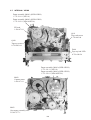
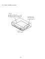
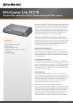
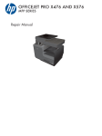
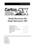
SLV-SE310/SE410/SE510
RMT-V257B/V257C
SERVICE MANUAL
AEP Model
SLV-SE310D/SE510B/D/SE510D
UK Model
SLV-SE310I
East European Model
Russian Model
SLV-SE410K/SE510K
Photo: SLV-SE510
• Refer to the SERVICE MANUAL of VHS MECHANICAL
ADJUSTMENTS VI for MECHANICAL ADJUSTMENTS.
(9-921-647-11)
S MECHANISM
The abbreviations of SE310/SE410/SE510 contained in this service manual are indicated
when these models are common to all their corresponding models as given below.
Abbreviated
models name
All model names
SLV-
SE310
SE310D
SE310I
SE410
SE410K
SE510
SE510B
SE510D
SE510K
SPECIFICATIONS
System
Channel coverage
SLV-SE310I
PAL (I)
VHF IA to IJ, SA10 to SA13
UHF B21 to B69
CATV S01 to S05, S1 to S20
HYPER S21 to S41
SLV-SE410K/SE510K
PAL (B/G, D/K)
VHF E2–E12, R1–R12
UHF E21–E69, R21–R69
CATV S1–S41, S01–S05
SLV-SE310D/SE510D
PAL (B/G)
VHF E2 to E12
VHF Italian channel A to H
0
UHF E21 to E69
CATV S01 to S05, S1 to S2
HYPER S21 to S41
SLV-SE510B
SECAM (L) : VHF F2 to F10
UHF F21 to F69
CATV B to Q
HYPER S21 to S41
PAL (B/G) : VHF E2 to E12
VHF Italian channel A to H
UHF E21 to E69
CATV S01 to S05, S1 to S20
HYPER S21 to S41
RF output signal
UHF channels 21–69
Aerial out
75-ohm asymmetrical aerial socket
Tape speed
SP: PAL/MESECAM
23.39 mm/s (recording/playback)
SECAM 23.39 mm/s
(recording/playback)
NTSC
33.35 mm/s (playback only)
LP: PAL/MESECAM
11.70 mm/s (recording/playback)
SECAM 11.70 mm/s
(recording/playback)
NTSC
16.67 mm/s (playback only)
EP: NTSC
11.12 mm/s (playback only)
– Continued on next page –
VIDEO CASSETTE RECORDER
Maximum recording/playback time
10 hrs. in LP mode (with E300 tape)
Fast-forward and rewind time
Approx. 3 min. (with E180 tape)
Inputs and outputs
i LINE-1 (TV)
21-pin
Video input: pin 20
Audio input: pins 2 and 6
Video output: pin 19
Audio output: pins 1 and 3
DECODER/t LINE-2 IN
21-pin
Video input: pin 20
Audio input: pins 2 and 6
General
Supplied accessories
Power requirements
220 – 240 V AC, 50 Hz
Power consumption
18 W
1.5 W (POWER SAVE is set to ON,
minimum)
Operating temperature
5°C to 40°C
Storage temperature
–20°C to 60°C
Dimensions
Approx. 355 × 96 × 288 mm (w/h/d)
including projecting parts and controls
Mass
Approx. 3.7 kg
Remote commander (1)
R6 (size AA) batteries (2)
Aerial cable (1)
Design and specifications are subject to
change without notice.
SAFETY-RELATED COMPONENT WARNING!!
COMPONENTS IDENTIFIED BY MARK 0 OR DOTTED
LINE WITH MARK 0 ON THE SCHEMATIC DIAGRAMS
AND IN THE PARTS LIST ARE CRITICAL TO SAFE
OPERATION. REPLACE THESE COMPONENTS WITH
SONY PARTS WHOSE PART NUMBERS APPEAR AS
SHOWN IN THIS MANUAL OR IN SUPPLEMENTS PUBLISHED BY SONY.
SAFETY CHECK-OUT
After correcting the original service problem, perform the following
safety checks before releasing the set to the customer:
1.
2.
3.
4.
Look for parts which, through functioning, show obvious
signs of deterioration. Point them out to the customer and
recommend their replacement.
5. Check the B+ voltage to see it is at the values specified.
6. Flexible Circuit Board Repairing
• Keep the temperature of the soldering iron around 270˚C during repairing.
• Do not touch the soldering iron on the same conductor of the
circuit board (within 3 times).
• Be careful not to apply force on the conductor when soldering or unsoldering.
Check the area of your repair for unsoldered or poorly-soldered connections. Check the entire board surface for solder
splashes and bridges.
Check the interboard wiring to ensure that no wires are
"pinched" or contact high-wattage resistors.
Look for unauthorized replacement parts, particularly transistors, that were installed during a previous repair. Point
them out to the customer and recommend their replacement.
–2–
TABLE OF CONTENTS
Section
Title
Page
Section
SERVICE NOTE ...................................................................... 4
1.
INTERFACE, IC PIN FUNCTION DESCRIPTION
5-1.
System Control-Video/RP Block Interface
(MA-401 BOARD IC162) ...............................................
System Control-Servo Peripheral Circuit Interface
(MA-401 BOARD IC162) ...............................................
System Control-Mechanism Block Interface
(MA-401 BOARD IC162) ...............................................
System Control-System Control Peripheral Circuit
Interface (MA-401 BOARD IC162) ................................
System Control-Audio Block Interface
(MA-401 BOARD IC162) ...............................................
Servo/System Control Microprocessor Pin Functions
(MA-401 BOARD IC162) ...............................................
Mode Control Pin Functions
(MA-401 BOARD IC420) ...............................................
5-2.
5-3.
5-4.
2.
DISASSEMBLY
2-1.
2-2.
2-3.
2-4.
2-5.
2-6.
2-7.
2-8.
Upper Case Removal ....................................................
Front Panel Section Removal ........................................
Power Block (ETXNY272E2D) Removal .......................
Rear Panel Removal .....................................................
Mechanism Deck Removal ...........................................
MA-401 Board Removal ................................................
Internal Views ................................................................
Circuit Boards Location .................................................
3.
BLOCK DIAGRAMS
3-1.
3-2.
3-3.
3-4.
3-5.
Overall Block Diagram ...................................................
Video Block Diagram .....................................................
Servo/System Control Block Diagram ..........................
Audio/Tuner Block Diagram ...........................................
Power Block Diagram ....................................................
4.
PRINTED WIRING BOARDS AND
SCHEMATIC DIAGRAMS
4-1.
4-2.
Frame Schematic Diagram ............................................
Printed Wiring Boards and Schematic Diagrams .........
MA-401 Printed Wiring Board .......................................
MA-401 (Head Amp) Schematic Diagram ....................
MA-401 (Video, Audio) Schematic Diagram .................
MA-401 (SECAM) Schematic Diagram .........................
MA-401 (Servo/System Control)
Schematic Diagram .......................................................
MA-401 (I/O) Schematic Diagram .................................
MA-401 (Tuner) Schematic Diagram ............................
MA-401 (Mode Control) Schematic Diagram ................
MA-401 (Power Supply) Schematic Diagram ...............
KK-26 Schematic Diagram ............................................
KK-26 Printed Wiring Board ..........................................
ETXNY272E2D Printed Wiring Board ...........................
ETXNY272E2D Schematic Diagram ............................
5-5.
5-6.
2-1
2-1
2-1
2-1
2-2
2-2
2-3
2-4
Page
5.
GENERAL
Getting Started .............................................................. 1-1
Basic Operations ........................................................... 1-10
Additional Operations .................................................... 1-15
Title
5-7.
4-3
4-5
4-5
4-9
4-11
4-15
4-17
4-21
4-23
4-25
4-27
4-29
4-29
4-30
4-31
5-2
5-2
5-2
5-3
5-5
ERROR CODES ....................................................... 6-1
7.
ADJUSTMENTS
8.
7-1
7-1
7-1
7-1
7-1
7-1
7-1
7-2
7-2
7-2
7-2
7-3
7-3
7-3
7-3
7-3
7-3
7-3
7-4
REPAIR PARTS LIST
8-1. Exploded Views .............................................................
8-1-1. Front Panel and Cabinet Assemblies .......................
8-1-2. Chassis Assembly ....................................................
8-1-3. Mechanism Chassis Assembly (1) ...........................
8-1-4. Mechanism Chassis Assembly (2) ...........................
8-1-5. Mechanism Chassis Assembly (3) ...........................
8-2. Electrical Parts List .......................................................
–3–
5-1
6.
7-1. Mechanical Adjustments ...............................................
7-2. Electrical Adjustments ...................................................
2-1. Preparation Before Adjustments ...................................
2-1-1. Equipment Required ................................................
2-1-2. Equipment Connection .............................................
2-1-3. Set-up of Adjustment ...............................................
2-1-4. Alignment Tapes .......................................................
2-1-5. I/O Level and Impedance .........................................
2-1-6. Adjustment Sequence ..............................................
2-2. Power Supply Check .....................................................
2-2-1. Output Voltage Check ..............................................
2-3. Servo System Check .....................................................
2-3-1. RF Switching Position Adjustment ...........................
2-4. Audio System Adjustments ...........................................
2-4-1. Normal Audio System Adjustment ...........................
2-4-2. ACE Head Adjustment .............................................
2-4-3. E-E Output Level Check ...........................................
2-4-4. Frequency Response Check ....................................
2-5. Adjusting Parts Location Diagram ................................
3-1
3-3
3-5
3-7
3-9
5-1
8-1
8-1
8-2
8-3
8-4
8-5
8-6
SERVICE NOTE
1. DISASSEMBLY
• This set can be disassembled in the order shown below.
Note: Pages in
Pages in
indicated pages in the SERVICE MANUAL.
indicated pages in the VHS MECHANICAL ADJUSTMENT MANUAL VI.
Set
Upper Case
(Page 2-1)
Front Panel
Section
(Page 2-1)
Pinch Press
Block Ass’y
(Page 14)
Ground Shaft
Ass’y
(Page 13)
FL Complete
Ass’y
(Page 13)
Mechanism
Deck
(Page 2-2)
Drum
Ass’y
(Page 13)
Retainer
Plate
(Page 22)
Rubber
Belt
(Page 15)
Rubber
Belt
(Page 15)
MA-401
Board
(Page 2-2)
FL Slider
Block Ass’y
(Page 22)
Capstan
Motor
(Page 15)
Pully Gear
Ass’y
(Page 29)
Rotary
Switch
Cam Gear
(Page 23)
Cam Motor
Retainer
(Page 31)
Reel Direct
Ass’y
(Page 30)
Rubber
Belt
(Page 15)
Cam Motor
(Page 31)
Slider
(Page 26)
Loading
Gear (T, S)
(Page 28)
–4–
Rear
Panel
(Page 2-1)
Power Block
(ETXNY272E2D)
(Page 2-1)
Tuner
Unit
SLV-SE310/SE410/SE510
SECTION 2
DISASSEMBLY
Note: Follow the disassembly procedure in the numerical order given.
2-1. UPPER CASE REMOVAL
1 Two screws
(Case3 TP2)
2-3. POWER BLOCK (ETXNY272E2D)
REMOVAL
3 Upper case
2 Power cord
2 Two screws
(Case3 TP2)
3 Three screws
(B3)
4 Power block
(ETXNY272E2D)
1 Connector
(CN101)
2-4. REAR PANEL REMOVAL
2-2. FRONT PANEL SECTION REMOVAL
7 Rear panel
6 Two claws
5 Three claws
1 Power cord
2 Three claws
2 Harness
4 Two claws
4 Front panel
section
1 Connector
(CN460)
3 Three claws
2-1
3 Two flat cables
2-5. MECHANISM DECK REMOVAL
3 Flat cable
(FFM-001)
2 Flexible board
4 Flat cable (FAC-8)
(ACE head)
1 Connector
8 Screw
(FE head)
7 Screw
(BVTP3 × 12)
(BVTP3 × 12)
6 Claw
0 Mechanism
deck
9 Screw
(BVTP3 × 12)
5 Screw
(B3)
Note: When mounting the mechanism deck,
first align mark on the rotary switch.
2-6. MA-401 BOARD REMOVAL
1 Three screws
(B3)
2 MA-401 board
2-2
2-7. INTERNAL VIEWS
Drum assembly (M901) (DZH-92D-R)
1-772-361-11 (SE310)
Drum assembly (M901) (DZH-93D-R)
1-772-362-11 (SE410/SE510)
FE head
1-500-471-11
Q101
Tape end sensor
8-729-043-84
Q100
Tape top sensor
8-729-043-84
D100
Tape top/end LED
8-719-048-26
Drum assembly (M901) (DZH-92D-R)
1-772-361-11 (SE310)
Drum assembly (M901) (DZH-93D-R)
1-772-362-11 (SE410/SE510)
M902
Capstan motor
1-698-971-11
M903
Cam motor assembly
X-3947-577-1
2-3
2-8. CIRCUIT BOARDS LOCATION
MA-401
VIDEO, AUDIO, I/O,
SERVO/SYSTEM CONTROL,
TUNER, MODE CONTROL
(
)
KK-26
(DIAL TIMER)
2-4
2-4E
POWER BLOCK
(ETXNY272E2D)
(POWER SUPPLY)
SLV-SE310/SE410/SE510
SECTION 6
ERROR CODES
6-1. ERROR CODE INDICATION
•
Error codes are indicated using the lower 5 digits in the fluorescent display tube.
“At this time, Colon “:”between character is not indicated.”
Mode code indication when the error has occurred.
Error code
ERROR CODE
0
No error
1
Cam encoder error Loading direction
2
Cam encoder error Unloading direction
3
T reel error
4
S reel error
5
Capstan error
6
Drum error
7
Error on initializing
8
Cassette loading error
9
Reserve
MODE CODE
0
Power-on eject
10
FWD x1
20
REW play
1
Power-on initial
2
Power-off elect
11
FWD x2
21
Cas. loading
12
CUE
22
Tape loading
3
Power-off stop
4
FF
13
PB-pause
23
Power-off loading
14
RVS-pause
24
Mecha. error (Power on)
5
REW
15
RVS x1
25
Power-on eject initial
6
REC
16
RVS x2
26
Power-off eject initial
7
REC-pause
17
REV
27
APC REC
8
Power-on stop
18
Power-off initial
28
9
PB
19
Mecha. error (Power off)
6-1 E
Cas. loading
(No auto PB check)
SLV-SE310/SE410/SE510
SECTION 7
ADJUSTMENTS
2-1-3. Set-up of Adjustment
In this adjustment, PAL pattern generator is connected with LINE2 input terminal. When check to tuner, connected AERIAL terminal. Check that the synchronizing signal of the Y signal has an
amplitude of approximately 0.7 V and that the burst signal has an
amplitude of approximately 0.3 V and its waveform is flat. And
check that the level ratio of burst signal to “red” signal is 0.30 :
0.66. The video signal (color bar) used for electrical aligning this
unit is shown in Fig. 6-2-2.
7-1. MECHANICAL ADJUSTMENTS
For the mechanical adjustments, please refer to the
“VHS MECHANICAL ADJUSTMENT MANUAL
(S MECHANISM)” (9-921-647-11).
7-2. ELECTRICAL ADJUSTMENTS
See the adjusting part location diagram from on page 7-4
for the adjustment.
2-1.
White (75%)
PREPARATION BEFORE ADJUSTMENTS
2-1-1. Equipment Required
The measuring instruments used for this alignment include:
1) Monitor TV
2) Oscilloscope, dual-trace, bandwidth of 30 MHz or more, with
delay mode (A probe 10:1 should be used unless otherwise
specified.)
3) Frequency counter
4) PAL Pattern generator
5) Remote commander
6) Digital voltmeter
7) Audio generator
8) Audio level meter
9) Audio attenuator
10) Alignment tapes
KRV-51P (PAL) Part No. : 8-192-955-57
Approx. 0.7 V
2-1-4. Alignment Tape
• Contents of KRV-51P
1
2
3
4
VIDEO IN
Video output
(75Ω)
Burst signal
(Should be flat)
Fig. 7-2-2 Color Bar Signals of Pattern Generator
2-1-2. Equipment Connection
Unless otherwise specified, connect and adjust the measuring instruments as shown in the following diagram.
VCR
Red
Horizontal sync signal
Mode
Pattern generator
Approx.
0.3 V
Approx. 0.3 V
Monitor TV
VIDEO OUT
Fig. 7-2-1
7-1
SP
LP
Period
Video signal
Audio signal
Normal
Hi-Fi
7 minutes
3 minutes
7 minutes
3 minutes
Color bar
Monoscope
Color bar
Monoscope
400Hz
(L/R)
400Hz
2-1-5. Input/Output Levels and Impedance
Video input: LINE-1 (TV)/LINE-2 IN
Input signal: 1 Vp-p, 75 ohms, unbalanced,
sync negative
Video output: LINE-1 (TV)
Output signal: 1 Vp-p, 75 ohms, unbalanced,
sync negative
Audio input: LINE-1 (TV)/LINE-2 IN
Input level: –7.5 dBs
(0 dBs= 0.775 Vrms)
Input impedance: more than 47 kilohms
Audio output: LINE-1 (TV)
Standard level: –7.5 dBs at load impedance 47
kilohms
Output impedance: less than 10 kilohms
2-2.
POWER SUPPLY CHECK
2-2-1. Output Voltage Check (MA-401 Board)
Mode
STANDBY
2-1-6. Adjustment Sequence
The adjustments should be performed in the following sequence.
Power Supply Check
Servo System Adjustments
Audio System Adjustments
D5 V Check
Measurement point
Cathode of D606
Specified value
4.8 to 5.4 V
Mode
E-E
–11 V Check
Measurement point
Corrector of Q602
Specified value
SW +12 V Check
–13.5 to – 9.5 V
Measurement point
Specified value
IC601 pin 2 or corrector of Q612
11.7 to 12.3 V
SW +5 V Check
Measurement point
Emitter of Q600
Specified value
MTR12 V Check
4.8 to 5.4 V
Measurement point
Specified value
Corrector of Q601
12.6 to 13.6 V
SW +30 V Check
Measurement point
Corrector of Q720
Specified value
33.5 to 36.5 V
[Check Method]
1) Each of these supply voltages must meet its specified value.
7-2
2-3.
2-4-1. Normal Audio System Adjustment
• Make adjustment in the SP mode unless otherwise specified.
Use a normal VHS cassette for an adjustment tape.
• Set AUDIO MONITOR to normal.
SERVO SYSTEM CHECK
2-3-1.
RF Switching Position Adjustment
(MA-401 Board)
[Adjustment Purpose]
To adjust the link of the A-ch and B-ch of the tape playback outputs.
To make the unit compatible with other tapes and units. If this
specification is not satisfied, the link will appear on the screen and
the screen will be disrupted, etc.
Mode
Signal
Playback
Alignment tape: SP color bar portion
Measurement point
Measuring instrument
CH1: CN262 pin 1 (PB RF)
CH2: CN262 pin 2 (RF SWP)
Oscilloscope
Adjusting element
Specified value
Remote commander CH+/–
A=minimize
2-4-2. ACE Head Adjustment
Refer to the VHS mechanical adjustment manual
NISM) (9-921-647-11).
2-5.
ADJUSTING PARTS LOCATION DIAGRAM
MA-401 BOARD
(CONDUCTOR SIDE)
LINE-1(TV)
(S MECHA-
CN500
CN262
1
5
2-4-3. E-E Output Level Check
[Adjustment purpose]
Confirm that the output level adjust the reference input is within the
specification.
[Adjustment Method]
1) Playback the alignment tape.
2) Short CN262 pin 5 to Ground.
3) Check that “A P” is indicated on FL display.
4) Adjust so that part A becomes minimized at CH +/–.
5) Write data in EEPROM by pressing PAUSE button.
6) The display “A P” disappears and then the Adjustment mode
terminates.
Mode
Signal
E-E
400 Hz, –6.3 dBs
Measurement point
Measuring instrument
CN500 Pin 3
Audio level meter
Specified value
–6.3 ± 2 dBs
E
Q601
B
[Check Method]
1) Input signal of 400 Hz and –6.3 dBs to the J480.
2) Check that the audio output level is –6.3 ± 2 dBs.
2-4-4. Frequency Response Check
[Adjustment purpose]
Confirm that the frequency characteristic is within the specification.
A
CH1
PB RF
CH2
RF SWP
Mode
Signal
REC and PB (SP mode)
400 Hz, –26.3 dBs
7 kHz, –26.3 dBs
Measurement point
Measuring instrument
CN500 Pin 3
Audio level meter
Specified value
0 ± 3 dB
B
Q600
E
B
E
Q602
Note: Tape path adjustment must have been completed.
[Confirmation Method]
1) Supply a signal of 400 Hz, –26.3 dBs to J481 AUDIO IN.
2) Connect the audio level meter to CN500 Pin 3.
3) Adjust the attenuator so that the audio level meter will indicate –26.3 dBs.
4) Make recording in the SP mode.
5) Set an audio line input signal to 7 kHz and make recording.
6) Playback a recorded portion, and measure output levels at 400
Hz and 7 kHz.
7) Confirm that the 7 kHz playback output level within a range
of the 400 Hz playback output level 0 dB to ± 3 dB.
Fig. 7-2-3
2-4.
AUDIO SYSTEM ADJUSTMENTS
[Connecting Instruments]
CN500
3 A (L) OUT
4 A GND
J481 AUDIO IN
Audio oscillator
600 Ω
Audio level meter
or distortion meter
47 kΩ
Attenuator
VTR
Fig. 7-2-4
7-3
7-4 E