1
HD DIGITAL VIDEOCASSETTE RECORDER
SRW-5000
SRW-5500
INSTALLATION MANUAL
1st Edition (Revised 3)
Serial No. 10101 and Higher: SRW-5000 (SY)
Serial No. 10001 and Higher: SRW-5500 (SY)
! WARNING
This manual is intended for qualified service personnel only.
To reduce the risk of electric shock, fire or injury, do not perform any servicing other than that
contained in the operating instructions unless you are qualified to do so. Refer all servicing to
qualified service personnel.
! WARNUNG
Die Anleitung ist nur für qualifiziertes Fachpersonal bestimmt.
Alle Wartungsarbeiten dürfen nur von qualifiziertem Fachpersonal ausgeführt werden. Um die
Gefahr eines elektrischen Schlages, Feuergefahr und Verletzungen zu vermeiden, sind bei
Wartungsarbeiten strikt die Angaben in der Anleitung zu befolgen. Andere als die angegeben
Wartungsarbeiten dürfen nur von Personen ausgeführt werden, die eine spezielle Befähigung
dazu besitzen.
! AVERTISSEMENT
Ce manual est destiné uniquement aux personnes compétentes en charge de l’entretien. Afin
de réduire les risques de décharge électrique, d’incendie ou de blessure n’effectuer que les
réparations indiquées dans le mode d’emploi à moins d’être qualifié pour en effectuer d’autres.
Pour toute réparation faire appel à une personne compétente uniquement.
Attention-when the product is installed in Rack:
1. Prevention against overloading of branch circuit
When this product is installed in a rack and is
supplied power from an outlet on the rack, please
make sure that the rack does not overload the supply
circuit.
4. Prevention against achieving hazardous
condition due to uneven mechanical loading
When this product is installed in a rack, please make
sure that the rack does not achieve hazardous
condition due to uneven mechanical loading.
2. Providing protective earth
When this product is installed in a rack and is
supplied power from an outlet on the rack, please
confirm that the outlet is provided with a suitable
protective earth connection.
5. Install the equipment while taking the operating
temperature of the equipment into consideration
For the operating temperature of the equipment, refer
to the “1-3. Operating Conditions” in this manual.
3. Internal air ambient temperature of the rack
When this product is installed in a rack, please make
sure that the internal air ambient temperature of the
rack is within the specified limit of this product.
6. When performing the installation, keep the
following space away from walls in order to
obtain proper exhaust and radiation of heat.
Right, Left: 4 cm (1.6 inches) or more
Rear:
10 cm (4 inches) or more
When using a Ethernet cable:
For safety,do not connect to the connector for
peripheral device wiring that might have excessive
voltage.
SRW-5000/5500
For the customers in the Netherlands
Voor de klanten in Nederland
Hoe u de batterijen moet verwijderen, leest u in de
Onderhoudshandleiding.
Gooi de batterij niet weg maar lever deze in als klein
chemisch afval (KCA).
Für Kunden in Deutschland
Entsorgungshinweis: Bitte werfen Sie nur entladene
Batterien in die Sammelboxen beim Handel oder den
Kommunen. Entladen sind Batterien in der Regel dann,
wenn das Gerät abschaltet und signalisiert “Batterie
leer” oder nach längerer Gebrauchsdauer der Batterien
“nicht mehr einwandfrei funktioniert”. Um
sicherzugehen, kleben Sie die Batteriepole z.B. mit
einem Klebestreifen ab oder geben Sie die Batterien
einzeln in einen Plastikbeutel.
SRW-5000/5500
1 (P)
Table of Contents
Manual Structure
Purpose of this manual .............................................................................................. 2
Related manuals ......................................................................................................... 2
Trademark .................................................................................................................. 2
1. Installation
1-1.
1-2.
1-3.
1-4.
1-5.
1-6.
1-7.
1-8.
1-9.
1-10.
1-11.
1-12.
1-13.
1-14.
1-15.
1-16.
Installation Procedure .................................................................................. 1-1
Supplied Accessories .................................................................................. 1-1
Operating Conditions .................................................................................. 1-1
Power Supply .............................................................................................. 1-2
1-4-1. Voltage and Power Requirements .............................................. 1-2
1-4-2. Recommeded Power Cord .......................................................... 1-2
Installation Space ........................................................................................ 1-3
Rack Mounting ............................................................................................ 1-4
Matching Connectors and Cables ................................................................ 1-9
Signal Inputs and Outputs ......................................................................... 1-10
Switch Settings on Connector Panel ......................................................... 1-14
Switch Settings on Circuit Boards ............................................................ 1-15
1-10-1. APR-62 Board .......................................................................... 1-15
1-10-2. CUE-13 Board .......................................................................... 1-16
System Setting ........................................................................................... 1-17
1-11-1. Setting the System for SRW-5000 ........................................... 1-17
1-11-2. Setting the System for SRW-5500 ........................................... 1-20
1-11-3. Compatibility of REC and PB .................................................. 1-23
1-11-4. Setting to Store Meta Data ....................................................... 1-24
1-11-5. Input/Output Phase Settings ..................................................... 1-28
1-11-6. Storing and Reading System Settings in/from System Bank ... 1-30
1-11-7. Storing/Reading System Settings in/from Memory Stick ........ 1-32
1-11-8. Editing Titles of the System Bank ........................................... 1-35
1-11-9. Checking Saved System Bank Data in Detail .......................... 1-36
1-11-10. Compatibility of System Bank Data ........................................ 1-36
Opening/Closing the Lower Control Panel ............................................... 1-37
Reference System ...................................................................................... 1-38
Settings when Editor is Connected ........................................................... 1-39
1-14-1. Settings for Time Code ............................................................ 1-39
1-14-2. VTR Constant Values Settings of Editor ................................. 1-39
Removing/Reattaching Plug-in Board ...................................................... 1-40
Taking Out the Cassette in Tape Slacking ................................................ 1-41
Appendix A Setting Check Sheet
SRW-5000/5500
1
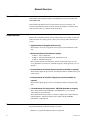
Manual Structure
Purpose of this manual
This manual is the installation manual of the HD Digital Videocassette Recorder
SRW-5000/5500.
This manual is intended for use by trained system and service engineers, and
provides the information that is required to install (environment, connection information, initial setting, etc.) and the setting check sheet.
Related manuals
Besides this “installation manual”, the following manuals are available for this unit.
If these manuals are required, please contact your local Sony Sales Office/Service
Center.
. Operation Manual (Supplied with this unit.)
This manual is necessary for application and operation (and installation) of this
unit.
. Maintenance Manual (Available on request)
Volume 1 : Service Instruction
Volume 2 : Parts List, Block Diagrams, and Board Layouts
Volume 3 : Schematic Diagrams
These manuals describe the maintenace and service information (service overview, adjustments, board layouts, schematic diagrams, detailed parts list, etc.) for
this unit.
. Protocol Manual of Remote (9-pin) Connector (Available on request)
This manual explains the protocol for controlling the VTR via the RS-422A (9-pin
serial remote).
. Interface Manual of Parallel I/O (50-pin) Connector (Available on
request)
This manual explains the protocol for controlling the VTR via the parallel (50pin).
. “Semiconductor Pin Assignments” CD-ROM (Available on request)
This “Semiconductor Pin Assignments” CD-ROM allows you to search for
semiconductors used in this unit.
The maintenance manual (volume 2) contains a complete list of semiconductors
and their ID Nos., and thus should be used together with the CD-ROM.
Part number: 9-968-546-XX
Trademark
Registered trademark used in this manual is as follows.
. Ethernet is a registered trademark of Xerox Corporation.
2
SRW-5000/5500
Section 1
Installation
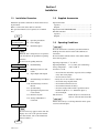
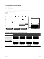
1-1. Installation Procedure
1-2. Supplied Accessories
Installation procedure of this unit is shown on the following flowchart.
Refer to each section about detail of each flow.
The operation manual is also required to do *-marked
flow.
Operation manual
Japanese ......................................................................... 1
English ........................................................................... 1
Operation manual CD-ROM (PDF) .................................. 1
Installation manual
Japanese ......................................................................... 1
English ........................................................................... 1
Start
Determination of
installation place
1-3. Operating Conditions
1-4. Power Supply
1-5. Installation Space
Unpacking
n
When the unit is transported, it is required to
pack the unit into the specified new packing
materials.
Do not reuse the packing materials.
Rack mounting
*Connection
*Initial setup
1-6. Rack Mounting
1-7. Matching Connectors and
Cables
1-8. Signal Inputs and Outputs
1-9. Switch Settings on Connector
Panel
1-10. Switch Settings on Circuit
Boards
1-11. System Setting
1-12. Opening/Closing the Lower
Control Panel
1-13. Reference System
1-14. Settings when Editor is
Connected
*Operation check
1-3. Operating Conditions
c
Good air circulation is essential to prevent internal heat
build-up. Place the unit in location with sufficient air
circulation.
Do not block the ventilation holes of the cabinet and the
front and rear panels.
Operating temperature: 5 dC to 40 dC
Operating humidity: 25 % to 80 % (non-condensing)
Storage temperature: _20 dC to 60 dC
Locations to avoid:
. Areas where the unit will be exposed to direct sunlight
of any other strong lights.
. Areas near heat sources.
. Dusty areas or areas subject to vibration.
. Areas with strong magnetic field.
. Areas with much electrical noise.
. Areas with much static electricity.
. Areas that is impossible to find a specified room for
installation. (Refer to “1-5. Installation Space”.)
. Areas windtight.
Tilt allowance:
Within 30d (Do not slant the front
and rear of the unit more than 30d.)
c
Fix the unit securely to avoid drop when the unit is operated at not-horizontal place.
n
If an error message appears on the time data
display area, refer to the operation manual.
(For more details, refer to the maintenance
manual volume 1.)
End
SRW-5000/5500
1-1
1-4. Power Supply
1-4-1. Voltage and Power Requirements
This unit’s power line has a switching regulator.
c
Be sure to operate the unit within the range of following
power voltage.
Power voltage:
AC 100 to 240 V ± 10 %
Power frequency:
50 Hz or 60 Hz
Power consumption: Maximum 320 W
(With all of the presumed optional kits.)
n
The power consumption becomes the
maximum at record-starting.
Rush current:
For customers in the U.S.A. and Canada:
1 Power cord 125 V 10 A (2.4 m):
! 1-557-377-11
2 Plug holder (Brown):
3-613-640-01
1
2
For customers in the United Kingdom:
1 Power cord 250 V 10 A (2.4 m):
2 Plug holder (Brown):
1
2
AC inlet
! 1-782-165-11
3-613-640-01
AC inlet
Power voltage 100 V IN: 17 A
Power voltage 240 V IN: 54 A
n
AC power supply is required a capacity which is commensurate with rush current.
If the capacity of the AC power supply is not enough, the
breaker of AC power of a supply side may operate or this
unit may not operate normally.
For customers in European countries except the United
Kingdom:
1 Power cord 250 V 10 A (2.0 m):
! 1-551-631-00
2 Plug holder (Brown):
3-613-640-01
1
2
AC inlet
1-4-2. Recommeded Power Cord
This unit does not come with a power cord.
To get a power cord, please contact your local Sony Sales
Office/Service Center.
w
. Use the approved Power Cord (3-core mains lead)/
Appliance Connector/Plug with earthing-contacts that
conforms to the safety regulations of each country if
applicable.
. Use the Power Cord (3-core mains lead)/Appliance
Connector/Plug conforming to the proper ratings (Voltage, Ampere).
If you have questions on the use of the above Power Cord/
Appliance Connector/Plug, please contact your local Sony
Sales Office/Service Center.
For customers in the China:
1 Power cord 250 V 10 A (1.8 m):
2 Plug holder (Brown):
1
2
! 1-783-481-41
3-613-640-01
AC inlet
If the unit is used in the area except above, please contact
your local Sony Sales Office/Service Center.
w
. Never use an injured power cord.
1-2
SRW-5000/5500
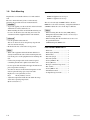
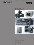
1-5. Installation Space
When installing, the installation space must be secured in
consideration of the ventilation and service operation.
. Do not block the ventilation slots at the left side and
right side panels, and vents of the fans.
. Leave a space around the unit for ventilation.
. Leave more than 40 centimeters of space in the rear of
the unit to secure the operation area.
When the unit is installed on the desk or the like, leave at
least four centimeters of space in the left and right sides.
Leaving 40 centimeters or more of space above the unit is
recommended for service operation.
Moreover, an air flow that is effective in cooling the unit is
essential. If the ventilation is not enough, the unit may be
damaged because of an increase of the internal temperature.
n
This unit is air-cooled by the fans. The operation with the
upper lid is removed affects the air cooling by the fans.
Complete the work in a short time as possible when
operating the unit for inspection with the upper lid removed. If it takes a long time, blow to the unit by an
electric fan to cool the unit.
538.5
416(Rail-installed width)
427(Unit width)
(Mass of this unit : approx. 30 kg)
45.5
533
577(Maximum traveling distance)
153.5
39.5
454
15.9
20
32
156
218
220
149.2
32
37
482
465
31.5
364
427
34
12.7
123.8
263.5
42.5
n Remove the feet when rack mounting.
415.9
457.5
(38.5)
Unit : mm
Dimensions when Rack-Mounting
SRW-5000/5500
1-3
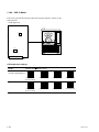
1-6. Rack Mounting
Explains how to mount this unit into a 19-inch standard
rack.
Be sure to mount this unit (*) into a rack accurately
following the procedure and notes mentioned below.
w
. To prevent toppling over the rack, fix it on the horizontal
and firm floor securely with bolts, etc.
. When installing the unit in an Outside Broadcasting van,
be sure to fix the unit to the rack using the screws and
ornamental washers supplied with the rack mount kit.
c
. Use the specified rack mount rail.
The use of other rail of low strength may drop the unit
and cause the risk of injury.
. Mount the unit into a rack with a steady posture.
m
. When other equipment with built-in hard disk drive is
already mounted in the same rack for mounting this unit,
turn off the power of the equipment before mounting this
unit.
. Connect long enough cables on the connector panel,
considering that the unit is pulled out from the rack.
. Do not operate this unit without the upper lid and bottom
plate except when servicing it.
. To reduce an increase in the internal temperature of this
unit, keep the following space away from walls.
Right, Left: 4 cm (1.6 inches) or more
Rear:
10 cm (4 inches) or more
. Adjust the temperature inside the rack within the range
of the unit’s operating temperature.
(Refer to Section 1-3.)
1-4
Specified Rack Mount Kit
RMM-110 (Optional accessory) or
RMM-111 (Optional accessory)
The color of rack angle of RMM-110 fits to the unit.
RMM-111 is the same consistency, strength and dimension
as RMM-110, but the color of rack angle is different.
m
. When mounting this unit into Sony LMS (Library
Management System) VTR console, it is necessary to
modify the VTR console.
. When mounting this unit into Flexicart, be sure to use
the specified kit below.
VTR Mounting Kit: BKFC-53/3
Parts Packed in RMM-110/111
.
.
.
.
.
.
.
.
.
.
.
.
Slide rails .........................................
Rack angles (handles) .....................
Rail brackets ....................................
Plate nuts (large) .............................
Plate nuts (small) .............................
Screws (PSW4 x 16) ......................
Screws (B4 x 8) ..............................
Hexagon socket head cap screws ....
Flat washers .....................................
Screws (RK5 x 14) .........................
Ornamental washers ........................
L-shaped hexagon wrench ..............
2
2
4
4
4
4
8
8
8
2
2
1
SRW-5000/5500
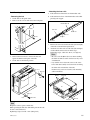
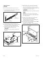
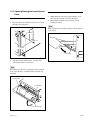
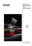
Rack Mounting Procedure
. Removing the feet
1. Set the unit its side panel down.
2. Remove the two screws and remove the lock plates.
. Attaching the inner rails
5. Pull each inner rail from the two intermediate rails.
6. Pull each inner rail out of the intermediate rails while
pressing each stopper.
Intermediate rail
Lock plate
Inner rail
Outer rail
Press
B3 x 6
Stopper
Pull out
Lock plate
3. Unscrew the four screws to remove the feet and
spacers from the bottom plate of the unit.
4. Set the unit in a horizontal position.
Feet
Spacers
7. Remove the ten screws from both sides (left and right)
of the unit as shown in the figure below.
8. Attach the two inner rails to both sides (left and right)
of unit with the removed screws in the step 7.
Tightening torque: 120 x 10 _2 N.m {12.2 kgf.cm}
m
. Be sure to use the (B4 x 6) screws when attaching
the inner rail. The use other-sized screws may cause
a malfunction.
. Pay attention not to fasten the screws to the screw
holes other than actually used screw holes for fixing
the inner rails on both sides of the unit.
If unnecessary screws are fastened, rack mounting
will be unenabled.
B4 x 6
Inner rail
PS4 x 20
Spacers
Feet
PS4 x 20
Inner rail
B4 x 6
n
Keep these screws, spacers and the feet.
When operating the unit after demounting it from the rack,
be sure to reattach the feet.
Tightening torque: 98 x 10 _2 N.m {10 kgf.cm}
SRW-5000/5500
1-5
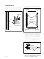
. Attaching the rack angles (handles)
9. Remove the four screws from both sides (left and
right) of the unit.
B4 x 6
. Loosely attaching the rail brackets
11. Slide the intermediate rail as shown in the figure, and
then loosely attach the rear rail bracket to the outer rail
with a plate nut (large) and the two screws.
Plate nut (large)
Rail bracket
Outer rail
Slide
B4 x 8
Intermediate rail
B4 x 6
n
Keep these screws (B4 x 6).
Be sure to use these screws when directly fixing the
side panels without the rack angles.
The use of longer screws such as the screws (PSW 4 x
16) for fixing the rack angles will cause a malfunction
of the unit.
12. Slide the ball retainer in the direction of the arrow, and
then loosely attach the front rail bracket to the outer
rail with a plate nut (large) and the two screws.
Outer rail
Plate nut (large)
Rail bracket
Slide
10. Attach the two rack angles to both sides (left and right)
of the unit with the four screws (PSW4 x 16) supplied
with the rack mount kit.
Tightening torque: 120 x 10 _2 N.m {12.2 kgf.cm}
Intermediate
rail
Ball retainer
B4 x 8
PSW4 x 16
Rack angle
PSW4 x 16
Rack angle
PSW4 x 16
1-6
SRW-5000/5500
. Attaching the outer rails
13. Loosely attach the two outer rails to the middle of the
5U space in the rack for mounting this unit, with the
eight hexagon socket head cap screws, eight flat
washers, and four plate nuts (small).
14. Check that the two intermediate rails attached to the
rack are parallel.
Hexagon socket
head cap screw
2 pcs
Hexagon socket
head cap screw
2 pcs
A
Rear side
Plate nut (small)
Rail bracket fixing screws
By 5U
Intermediate rails
Rail
Rail bracket fixing screws
Flat washer
2U
Hexagon socket
head cap screw
L-shaped hexagon wrench
Front side
A'
Hexagon socket
head cap screw
2 pcs
A = A' = 416 mm
Hexagon socket
head cap screw
2 pcs
15. As shown in the following figure, adjust each frontside position of the outer rails on both sides (left and
right) so that the distance from the surface of the rack
to the tip of the rail becomes within the range of 50 to
55 millimeters.
16. To fix the four rail brackets, fully tighten the eight
loosely fitted rail bracket fixing screws (B4 x 8) in
steps 11 and 12.
Tightening torque: 120 x 10 _2 N.m {12.2 kgf.cm}
Rack
Rail bracket
Outer rail
50 to 55 mm
Rack angle
SRW-5000/5500
Rail bracket fixing screws
B4 x 8
17. To fix the two outer rails to the rack, fully tighten the
eight loosely fitted hexagon socket head cap screws in
step 13 using the L-shaped hexagon wrench.
1-7
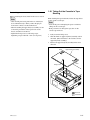
. Mounting in rack
c
Be sure to carry the unit by the two persons or more.
18. Set each ball retainer to the position as shown in the
figure in the direction of the arrow.
Front side
Intermediate rail
Slide
Ball retainer
19. Pull equal length of each rail on both sides out.
20. Lift the unit holding the gripes on both sides, slowly
insert the inner rails into the intermediate rails.
21. While pressing each stopper of inner rails on both
sides, slowly push the unit into the rack.
c
Be careful not to catch your finger or hand in rack
mount rail.
22. Slide the unit in and out from the rack about three
times and check that the slide rails move smoothly.
If they are not smoothly, demount the unit and go back
to “Attaching the outer rails” (step 13).
c
When demounting the unit, carry it by the two persons
or more.
n
This unit does not have the feet at this operating.
Put down the unit on the floor or other, being careful
not to damage the unit.
23. Push the unit in the depths of the rack. The unit is
fixed to the rack by the lock mechanism.
Attempt to pull the rack angles and confirm that the
unit cannot be pulled out of the rack.
24. Secure the unit to the rack with the four screws (RK5
x 14) and four ornamental washers.
Tightening torque: 120 x 10 _2 N.m {12.2 kgf.cm}
Ornamental
washer
RK5 x 14
Stopper
RK5 x 14
Intermediate rail
Ornamental
washer
Stopper
Inner rail
1-8
SRW-5000/5500
1-7. Matching Connectors and Cables
When external cables are connected to the connector of this unit, the hardware listed below (or equivalents) must be used.
Panel indication
Matching connector (cable)
Sony part No.
TIME CODE IN
CUE IN
XLR 3P, MALE
1-508-084-00
AUDIO OUTPUT
CUE OUT
MONITOR OUTPUT
TIME CODE OUT
XLR 3P, FEMALE
1-508-083-00
REF. INPUT
HD REF. OUT
SD OUT
BNC 75Z, MALE
1-569-370-12
AUDIO INPUT (AES/EBU)
AUDIO OUTPUT (AES/EBU)
BNC 75Z, MALE (*1)
1-569-370-12
REMOTE 2 PARALLEL I/O (50P)
D-SUB 50P, MALE and
JUNCTION SHELL 50P
1-565-516-11
1-563-379-11
REMOTE 1-IN (9P)
REMOTE 1-I/O (9P)
9P remote control cable (RCC-G series)
or
D-SUB 9P, MALE and
JUNCTION SHEEL 9P
_
or
1-560-651-00
1-561-749-00
RS232C
D-SUB 9P, FEMALE
1-563-815-21
VIDEO CONTROL (9P)
D-SUB 9P, MALE and
JUNCTION SHELL 9P
1-561-651-00
1-561-749-00
HD SDI INPUT
HD SDI OUTPUT
FORMAT CONV. OUT (OPTION)
FC OUT B (OPTION)
BNC 75Z, MALE (*2)
1-569-370-12
SD SDI OUT
BNC 75Z, MALE (*3)
1-569-370-12
PHONES
JM-60 stereo phone plug
_
ETHERNET
Separately available
USB
Separately available
Remarks
Upper control panel
*1: Coaxial cable length : max. 600 meters (Reference value based on this unit)
It is recommended to connect the BELDEN 8281 cable or equivalent to this connector.
*2: Coaxial cable length : max. 100 meters (Reference value based on this unit)
It is recommended to connect the BELDEN 1694A cable or equivalent to this connector.
*3: Coaxial cable length : max. 200 meters (Reference value based on this unit)
It is recommended to connect the BELDEN 8281 cable or equivalent to this connector.
SRW-5000/5500
1-9
1-8. Signal Inputs and Outputs
Reduced drawing of rear panel
1
2
3
5
4
Input connectors
1 TIME CODE IN
XLR 3-pin x 1
Time code 0.5 to 18 V p-p, 10 kZ, balanced
1 CUE IN
(SRW-5500 only)
XLR 3-pin x 1
Analog audio
+4 dBm (Standard) 600 Z termination, balanced (when ON)
+4 dBu (Standard), high impedance, balanced (when OFF)
2 REF. INPUT 1
REF. INPUT 2 (OPTION)
BNC x 4 (Loop through output x 2)
External reference video signal
HD : 0.6 V p-p, 75 Z, sync negative (HD analog tri-level sync)
SD : 0.3 V p-p, 75 Z, sync negative (Black burst or composite sync)
3 AUDIO INPUT (AES/EBU)
BNC x 6 (1 set : CH1/2, CH3/4, CH5/6, CH7/8, CH9/10, and CH11/12)
AES/EBU digital audio
Complies with SMPTE 299M, SMPTE 276 (AES-3id-1995)
5 HD SDI INPUT A
BNC x 1 (outputs the input monitor x 1)
Serial digital interface (1.485 Gbit/s), complies with SMPTE 292M, SMPTE 372M
5 HD SDI INPUT B (OPTION)
(Option HKSR-5003)
BNC x 1 (outputs the input monitor x 1)
Serial digital interface (1.485 Gbit/s), complies with SMPTE 292M, SMPTE 372M
Remote connectors
4 REMOTE 2 PARALLEL I/O (50P) *
D-SUB 50P connector
4 REMOTE1-IN (9P)
D-SUB 9P connector (RS-422A interface), Remote control
4 REMOTE1-I/O (9P)
D-SUB 9P connector (RS-422A interface), Remote control
4 RS232C
D-SUB 9P connector (RS-232C interface) for ISR (Interactive Status Reporting)
4 VIDEO CONTROL (9P)
D-SUB 9P connector for a HD digital video controller (HKDV-900) connection
4 ETHERNET
RJ-45 modular jack
Complied with 10BASE-T/100BASE-TX
4 USB
USB series B
Complied with USB standard Ver 1.1
* : Refer to Optional “Interface manual” for details.
1-10
SRW-5000/5500
Output connectors
1 AUDIO OUTPUT
XLR 3-pin x 4 (1 set : CH1, CH2, CH3, and CH4)
Analog audio
+4 dBm (Standard) (600 Z load), low impedance, balanced
1 CUE OUT
XLR 3-pin x 1
Analog audio
+4 dBm (Standard) (600 Z load), low impedance, balanced
1 TIME CODE OUT
XLR 3-pin x 1
Time code 2.2 V p-p, low impedance, balanced
1 MONITOR OUTPUT
XLR 3-pin x 2 (1 set : L and R)
Analog audio
+4 dBm (Standard) (600 Z load), low impedance, balanced
2 HD REF. OUT
BNC x 2
0.6 V p-p, 75 Z, sync negative (HD analog tri-level sync)
2 SD OUT COMPOSITE (MONITOR)
BNC x 1 (for character superimpose)
Analog composite video
VBS : 1.0 V p-p, 75 Z, sync negative
2 SD OUT SYNC
BNC x 1
SYNC (NTSC/PAL) : 0.286/0.3 V p-p, 75 Z, sync negative
BURST (NTSC/PAL) : 0.286/0.3 V p-p, 75 Z, sync negative
3 AUDIO OUTPUT (AES/EBU)
BNC x 6 (1 set : CH1/2, CH3/4, CH5/6, CH7/8, CH9/10, and CH11/12)
AES/EBU digital audio
Complies with SMPTE 299M, SMPTE 276M (AES-3id-1995)
5 HD SDI OUTPUT A
BNC x 3 (including 1 for character superimpose)
Serial digital interface (1.485 Gbit/s), complies with SMPTE 292M, SMPTE 372M
5 HD SDI OUTPUT B (OPTION)
(Option HKSR-5003)
BNC x 3 (including 1 for character superimpose)
Serial digital interface (1.485 Gbit/s), complies with SMPTE 292M, SMPTE 372M
5 SD SDI OUTPUT
BNC x 3 (including 1 for character superimpose)
Serial digital interface (270 Mbit/s), complies with SMPTE 259M, ITU-R BT.656
5 FORMAT CONV. OUT (OPTION)
(Option HKSR-5001)
BNC x 2 (for character superimpose)
Serial digital interface (1.485 Gbit/s), complies with SMPTE 292M, SMPTE 372M
5 FC OUT B (OPTION)
(Option HKSR-5001)
BNC x 2 (for character superimpose)
Serial digital interface (1.485 Gbit/s), complies with SMPTE 292M, SMPTE 372M
PHONES
(Upper control panel)
JM-60 stereo phone jack
Analog audio
up to _12 dBu (8 Z load), unbalanced
Other
Memory stick
(Lower control panel)
SRW-5000/5500
Memory stick x 1
Applicable memory stick : 8 MB to 128 MB
n
The memory card (PCMCIA type) can be used by removing the memory stick adaptor
under the lower control panel.
For removing the memory stick adaptor, refer to the maintenance manual volume 1.
1-11
REMOTE 2 PARALLEL I/O: 50-pin (female)
External view
17
1
33
18
50
34
Pin No.
I/O *1
Setting change *2
Signal
Description
1
IN
O
FF
CLOSURE SW (FF)
2
OUT
X
REC SW
PANEL REC SW OUT
3
OUT
X
PLAY SW
PANEL PLAY SW OUT
4
OUT
X
STOP SW
PANEL STOP SW OUT
5
OUT
X
ENTRY SW
PANEL ENTRY SW OUT
6
OUT
X
REF SYSTEM ALARM
Non-REFERENCE
7
OUT
X
CF LOCK
COLOR FRAME LOCK STATUS
8
OUT
X
DRUM LOCK
LOCK STATUS OF DRUM SERVO
9
OUT
X
CAP LOCK
LOCK STATUS OF CAPSTAN SERVO
10
OUT
O
CUE PRESET
EDIT PRESET STATUS of the CUE Channel
11
OUT
O
TC PRESET
EDIT PRESET STATUS of the TC Channel
12
OUT
O
CASSETTE OUT/IN
CASSETTE OUT/IN STATUS
13
OUT
O
TAPE HDCAM SR
TAPE STATUS
14
OUT
X
SPARE
SPARE
15
OUT
X
SPARE
SPARE
16
——
——
+12V
(Maximum output current 50 mA)
17
——
——
GND
SIGNAL GND
18
IN
O
PREROLL
CLOSURE SW (PREROLL)
19
IN
O
STBY ON
CLOSURE SW (STANDBY ON)
20
IN
O
REW
CLOSURE SW (REW)
21
IN
O
ENTRY IN
CLOSURE SW (ENTRY IN)
22
IN
O
STBY OFF
CLOSURE SW (STANDBY OFF)
23
IN
O
EJECT
CLOSURE SW (EJECT)
24
OUT
X
REC
REC STATUS
25
OUT
X
CH CONDITION RED
CHANNEL CONDITION RED STATUS
26
OUT
O
ASSEMBLE PRESET
ASSEMBLE PRESET STATUS
27
OUT
O
EDIT OUT
EDIT STATUS
28
OUT
O
EJECT OUT
EJECT STATUS
29
OUT
O
ETHERNET
ETHERNET STATUS
30
OUT
O
REEL HUB
REEL HUB STATUS
31
OUT
X
CURRENT SETUP DATA CHANGE
CURRENT SETUP DATA CHANGE STATUS
32
OUT
X
ALL REC INHIBIT
ALL REC INHIBIT STATUS
33
——
——
GND
34
IN
O
PLAY
CLOSURE SW (PLAY)
35
IN
O
STOP
CLOSURE SW (STOP)
(Continue)
1-12
SRW-5000/5500
(Continued)
Pin No.
I/O *1
Setting change *2 Signal
Description
36
IN
O
REC
CLOSURE SW (REC)
37
OUT
X
REV LAMP
REV LAMP STATUS
38
OUT
O
DA2 PRESET
DA2 EDIT PRESET STATUS
39
OUT
O
DA1 PRESET
DA1 EDIT PRESET STATUS
40
OUT
X
FWD LAMP
FWD LAMP STATUS
41
OUT
O
DA4 PRESET
DA4 EDIT PRESET STATUS
42
OUT
O
DA3 PRESET
DA3 EDIT PRESET STATUS
43
OUT
X
STOP
STOP STATUS
44
OUT
O
VIDEO PRESET
VIDEO EDIT PRESET STATUS
45
OUT
O
INSERT PRESET
INSERT EDIT PRESET STATUS
46
OUT
X
STBY ON
STANDBY ON STATUS
47
OUT
X
PLAY
PLAY STATUS
48
OUT
X
REMOTE
REMOTE STATUS
49
OUT
X
ALARM
SYSTEM ALARM STATUS
50
OUT
O
PREROLL
PREROLL STATUS
*1: Input ; 47 kZ pull up to +5 V (close/open)
Output ; 10 kZ pull up to +5 V (0 V or open)
*2: The pins described as O mark are possible to change the setting.
Refer to the optional interface manual for changing the setting.
REMOTE 1-IN: 9-pin (female)
REMOTE 1-I/O: 9-pin (female)
RS232C: 9-pin (male)
External view
External view
5
1
1
9
5
6
6
9
Pin No.
Signal
Pin No.
Signal
1
GND
1
DCD ; Data Carrier Detect (Input)
2
RM TX(_)
2
RXD ; Received Data (Input)
3
RM RX(+)
3
TXD ; Transmitted Data (Output)
4
GND
4
DTR ; Data Terminal Ready (Output)
5
PRIORITY
5
SG ; Signal Ground
6
GND
6
DSR ; Data Set Ready (Input)
7
RM TX(+)
7
RTS ; Request to Send (Output)
8
RM RX(_)
8
CTS ; Clear to Send (Input)
9
GND
9
NC
SRW-5000/5500
1-13
VIDEO CONTROL: 9-pin (female)
External view
5
USB: USB series B
Standard : USB standard Ver1.1
1
9
External view
6
2
1
3
4
Pin No.
Signal
Pin No.
I/O
Signal
1
GND
1
–
Vcc (+5 V)
2
RM TX (_)
2
I/O
DATA (_)
3
RM RX (+)
3
I/O
DATA (+)
4
GND
4
–
GND
5
——
6
GND
7
RM TX (+)
8
RM RX (_)
9
GND
1-9. Switch Settings on Connector Panel
ETHERNET: RJ-45 modular jack
Standard : Complied with IEEE 802.3u (100BASE-TX)
and IEEE 802.3 (10BASE-T)
When the unit is installed, be sure to perform the following
setup.
Refer to the operation manual “Section 2 Location and
Function of Parts” for setup.
. 75 Z termination switch of reference video input
. 600 Z termination switch of CUE input
External view
8
1
Pin No.
I/O
Signal
1
O
TXD (+)
2
O
TXD (_)
3
I
RXD (+)
4
—
NC
5
—
NC
6
I
RXD (_)
7
—
NC
8
—
NC
1-14
SRW-5000/5500
1-10. Switch Settings on Circuit Boards
1-10-1. APR-62 Board
If necessary, perform the following audio-related settings using the switches on the APR-62 board.
. Analog audio output level/output headroom
. Monitor output level/output headroom
m
. Refer to Section 1-15 for removing and reattaching the plug-in boards.
. The switches S400, S701, S6100 are Factory use. Never change the setting.
A
B
C
D
E
F
G
S701
1
S6100
(Board No. suffix -14)
2
S400
S2300 S1300
3
S4200 S3200 S2200 S1200
4
< Top View >
APR-62 Board (Side A)
Analog audio and Monitor output level/output headroom settings
Channel
Ref. No.
\ : Knob position)
Switches state (\
S1200
O
N
O
N
O
N
CH2
S2200
CH3
S3200
1
2
3
4
5
6
7
8
1
2
3
4
5
6
7
8
1
2
3
4
5
6
7
8
CH4
S4200
_3 dBm/_18 dB
+1 dBm/_18 dB
0 dBm/_18 dB
R
S1300
+4 dBm/_20 dB
(Factory setting)
L
S2300
SRW-5000/5500
O
N
O
N
O
N
O
N
1
2
3
4
5
6
7
8
1
2
3
4
5
6
7
8
1
2
3
4
5
6
7
8
1
2
3
4
5
6
7
8
O
N
CH1
1
2
3
4
5
6
7
8
Output level (600 Z)/Output headroom
0 dBm/_12 dB
+4 dBm/_18 dB
+4 dBm/_16 dB
0 dBm/_20 dB
+6 dBm/_20 dB
1-15
1-10-2. CUE-13 Board
If necessary, perform the following audio-related settings using the switches on the
CUE-13 board.
. CUE output level
1
2
A
S101
B
C
S100
D
< Top View >
CUE-13 Board (Side A)
CUE output level settings
1-16
O
N
O
N
1
2
3
4
O
N
1
2
3
4
_20 dBm/600 Z
O
N
O
N
1
2
3
4
O
N
0 dBm/600 Z
_3 dBm/600 Z
1
2
3
4
+4 dBm/600 Z
(Factory setting)
0 dBm/600 Z
1
2
3
4
1
2
3
4
S101
O
N
+4 dBm/600 Z
(Factory setting)
1
2
3
4
1
2
3
4
S100
(available in SRW-5500 only)
\ : Knob position)
Switches state (\
O
N
Ref. No.
_3 dBm/600 Z
_20 dBm/600 Z
SRW-5000/5500
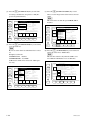
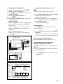
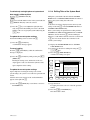
1-11. System Setting
1-11-1. Setting the System for SRW-5000
1. Activating the system menu
(1) Turn on the power.
(2) Press the DIAG button while pressing the [SFT]
(SHIFT) key.
(3) Press the [F8] (MAINTE EXEC) key while pressing
the [SFT] (SHIFT) key.
(4) Press the [F9] (OTHERS CHECK) key.
(5) Press the [F9] (SYSTEM MENU) key to display the
system menu.
2. Setting the system
Set the system referring to the table “1-11-3. Compatibility
of REC and PB”.
n
The selectable systems differ according to the VTR
settings (operation mode) or option boards.
(1) Press the [F4] (SYSTEM SIGNAL) key several times
for setting to the 4:2:2 or 4:4:4.
n
The 4:4:4 can be selected when the option HKSR-5003
is installed.
F1
1 [SFT] + DIAG
F2
SFT
F3
F1
F2
2 [SFT] + [F8]
F3
F4
DIAG
ALT
F5
F6
F7
F8
F9 F10
3, 4 [F9]
F4
SYSTEM
LINE
1080/59.94i 422 YPbPr
1080
SYSTEM [F1]SYSTEM LINE
[F2]SYSTEM
SCAN MODE Interlace
SCAN
[F3]SYSTEM FRAME
29.97Hz
SYSTEM [F4]SYSTEM SIGNAL MODE 422
FRAME
[F6]FRAME CONVERT
1080/59.94i
422 YPbPr LINE
[F7]ACTIVE
1080
SYSTEM
[F8]CANCEL
[F9]Exec
of
Reset
VTR Sys
444 RGB
SIGNAL
(STOP & STANDBY OFF/EJECT)
FRAME ACTIVE CANCEL EXEC
CNVERT LINE
DIAG
ALT
SYSTEM MENU
F5
F6
F7
F8
EXIT
F9 F10
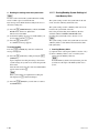
(2) Press the [F1] (SYSTEM LINE) key several times for
setting to the 1080 x 1920 or 720 x 1280.
F1
F2
F3
F4
SYSTEM
LINE
1080/59.94i 422 YPbPr
LINE
1080
SYSTEM [F1]SYSTEM
1080
SCAN MODE Interlace
SCAN [F2]SYSTEM
[F3]SYSTEM
FRAME
29.97Hz
720
SYSTEM [F4]SYSTEM SIGNAL MODE 422
FRAME
[F6]FRAME CONVERT
1080/59.94i
1080
SYSTEM [F7]ACTIVE LINE
SIGNAL [F8]CANCEL [F9]Exec of Reset VTR Sys
(STOP & STANDBY OFF/EJECT)
FRAME ACTIVE CANCEL EXEC
CNVERT LINE
DIAG
ALT
SRW-5000/5500
SYSTEM MENU
F5
F6
F7
F8
EXIT
F9 F10
1-17
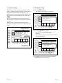
(3) Press the [F2] (SYSTEM SCAN) key several times
for setting to the Interlace, Progressive or PsF (Progressive Segmented Frame).
F1
F2
F3
F4
SYSTEM
LINE
1080/59.94i 422 YPbPr
LINE
1080
SYSTEM [F1]SYSTEM
Interlace
[F2]SYSTEM
SCAN MODE Interlace
SCAN
[F3]SYSTEM
FRAME
29.97Hz
PsF
Progressive SIGNAL MODE 422
SYSTEM [F4]SYSTEM
FRAME
[F6]FRAME CONVERT
1080/59.94i
1080
SYSTEM [F7]ACTIVE LINE
[F8]CANCEL
[F9]Exec
of
Reset
VTR Sys
SIGNAL
(STOP & STANDBY OFF/EJECT)
FRAME ACTIVE CANCEL EXEC
CNVERT LINE
DIAG
ALT
SYSTEM MENU
F5
F6
F7
F8
(5) Press the [F6] (FRAME CONVERT) key several
times to set the image format of the format converter
output.
n
This item can be set when the option HKSR-5001 is
installed.
F1
SYSTEM
LINE
F2
SYSTEM
SCAN
EXIT
F3
F9 F10
F4
SYSTEM
FRAME
SYSTEM
SIGNAL
FRAME ACTIVE CANCEL EXEC
CNVERT LINE
DIAG
(4) Press the [F3] (SYSTEM FRAME) key several times
to set the frame rate.
n
Be sure to set the frame rate when Insterlace is selected.
Example) 59.94i mode
SYSTEM SCAM: Interlace
SYSTEM FRAME: 29.97 MHz
50 Hz and 59.94 Hz can be selected for 720 Progressive only.
ALT
SYSTEM
LINE
F2
SYSTEM
SCAN
F3
F4
SYSTEM
FRAME
SYSTEM
SIGNAL
FRAME ACTIVE CANCEL EXEC
CNVERT LINE
DIAG
ALT
1-18
F2
SYSTEM MENU
1080/59.94i 422 YPbPr
23.98Hz
[F1]SYSTEM
LINE
1080
24Hz
[F2]SYSTEM SCAN MODE Interlace
25Hz
[F3]SYSTEM FRAME
29.97Hz
[F4]SYSTEM
SIGNAL MODE 422
29.97Hz
30Hz
[F6]FRAME
CONVERT
1080/59.94i
50Hz
[F7]ACTIVE LINE
1080
59.94Hz
[F8]CANCEL [F9]Exec of Reset VTR Sys
(STOP & STANDBY OFF/EJECT)
F5
F6
F7
F8
F5
F6
F7
F8
EXIT
F9 F10
(6) Press the [F7] (ACTIVE LINE) key several times for
setting the active line to 1080 or 1035.
n
This becomes effective only when the VTR is set to
4:2:2 1080 x 1920 Interlace 29.97 or 30 frames.
F1
F1
SYSTEM MENU
1080/59.94i 422 YPbPr
1080/60i
[F1]SYSTEM
1080
1080/59.94i LINE
[F2]SYSTEM SCAN MODE Interlace
1080/50i
[F3]SYSTEM FRAME
29.97Hz
1080/30PsF SIGNAL MODE 422
[F4]SYSTEM
[F1080/29PsF
1080/25PsF CONVERT
[F6]FRAME
1080/59.94i
[F7]ACTIVE
1080
1080/24PsF LINE
[F8]CANCEL
[F9]Exec
of
Reset
VTR Sys
1080/23.98PsF
(STOP & STANDBY OFF/EJECT)
F3
F4
SYSTEM
LINE
SYSTEM MENU
1080/59.94i 422 YPbPr
1080
SYSTEM [F1]SYSTEM LINE
SCAN [F2]SYSTEM SCAN MODE Interlace
[F3]SYSTEM FRAME
29.97Hz
SYSTEM [F4]SYSTEM SIGNAL MODE 422
FRAME OFF
[F6]FRAME
CONVERT
1080/59.94i
1080
LINE
1080
SYSTEM [F7]ACTIVE
1035
[F8]CANCEL
[F9]Exec
of
Reset
VTR Sys
SIGNAL
(STOP & STANDBY OFF/EJECT)
FRAME ACTIVE CANCEL EXEC
CNVERT LINE
DIAG
EXIT
EXIT
ALT
F5
F6
F7
F8
F9 F10
F9 F10
SRW-5000/5500
3. Check the setting
Check that the content of system setting performed after
saving is displayed with white characters in the first line of
the system menu. Check further that the items to be
updated from the current system setting are displayed with
yellow characters to the right of respective setting items.
n
The faint white characters in the first line of the system
menu mean that a combination of unsettable system items
is selected.
Recheck and re-set the item shown with faint yellow
characters to the right of the item, etc. referring to Section
1-11-3.
Unsettable system status
(faint white characters)
F1
F2
F3
F4
SYSTEM
LINE
1080/25PsF 422 YPbPr AUTO
1080
SYSTEM [F1]SYSTEM LINE
[F2]SYSTEM
SCAN MODE PsF
SCAN
[F3]SYSTEM FRAME
25Hz
SYSTEM [F4]SYSTEM SIGNAL MODE 422 YPbPr
FRAME
[F6]FRAME CONVERT
444 1080/30PsF
1080
SYSTEM [F7]ACTIVE LINE
[F8]CANCEL
[F9]Exec
of
Reset
VTR Sys
SIGNAL
(STOP & STANDBY OFF/EJECT)
FRAME ACTIVE CANCEL EXEC
CNVERT LINE
DIAG
ALT
SYSTEM MENU
F5
F6
F7
F8
4. Storing the settings
(1) Press the [F9] (EXEC) key.
. The message “Are You Sure?” is displayed.
F1
F2
F3
F4
SYSTEM
LINE
1080/59.94i 422 YPbPr
LINE
1080
SYSTEM [F1]SYSTEM
!
Are You
Sure?
[F2]SYSTEM
SCAN
MODE Interlace
SCAN
[F3]SYSTEM FRAME
29.97Hz
If you press
[F9] again
SIGNAL
SYSTEM [F4]SYSTEM
then EXEC
U T E . MODE 422
FRAME
[F6]FRAME
1080/59.94i
Or pressCONVERT
[F8] to CANCEL.
1080
SYSTEM [F7]ACTIVE LINE
[F8]CANCEL
[F9]Exec
of
Reset
VTR Sys
SIGNAL
(STOP & STANDBY OFF/EJECT)
FRAME ACTIVE CANCEL EXEC
CNVERT LINE
DIAG
ALT
SYSTEM MENU
F5
F6
F7
F8
EXIT
F9 F10
(2) Press the [F9] (EXEC) key again.
. The message “SYSTEM REBOOTING......” is
displayed.
. On completing the store of the settings, the system is
restarted automatically.
EXIT
F9 F10
Unselectable item
(faint yellow characters)
F1
F2
F3
F4
SYSTEM
LINE
1080/59.94i 422 YPbPr
1080
SYSTEM [F1]SYSTEM LINE
SCAN [F2]SYSTEM SCAN MODE Interlace
[F3]SYSTEM FRAME
29.97Hz
SIGNAL MODE 422
SYSTEM [F4]SYSTEM
! SYSTEM REBOOTING......
FRAME [F5]SYSTEM REC FORMAT
[F6]FRAME
W a i t CONVERT
a moment.
1080
SYSTEM [F7]ACTIVE LINE
SIGNAL [F8]CANCEL [F9]Exec of Reset VTR Sys
(STOP & STANDBY OFF/EJECT)
FRAME ACTIVE CANCEL EXEC
CNVERT LINE
DIAG
ALT
SYSTEM MENU
F5
F6
F7
F8
EXIT
F9 F10
(3) Check that the system is restarted, and turn OFF the
POWER switch and turn ON again.
SRW-5000/5500
1-19
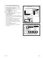
1-11-2. Setting the System for SRW-5500
1. Activating the system menu
(1) Turn on the power.
(2) Press the DIAG button while pressing the [SFT]
(SHIFT) key.
(3) Press the [F8] (MAINTE EXEC) key while pressing
the [SFT] (SHIFT) key.
(4) Press the [F9] (OTHERS CHECK) key.
(5) Press the [F9] (SYSTEM MENU) key to display the
system menu.
2. Setting the system
Set the system referring to the table “1-11-3. Compatibility
of REC and PB”.
n
The selectable systems differ according to the VTR
settings (operation mode) or option boards.
(1) Press the [F4] (SYSTEM SIGNAL) key several times
for setting to the 4:2:2 or 4:4:4.
n
The 4:4:4 can be selected when the option HKSR-5003
is installed.
1 [SFT] + DIAG
F1
SFT
F2
F1
F2
2 [SFT] + [F8]
F3
F4
DIAG
ALT
F3
F4
F5
F6
F7
F8
F9 F10
3, 4 [F9]
DIAG
ALT
SYSTEM
LINE
SYSTEM MENU
1080/59.94i 422 YPbPr HDCAM-SR
1080
SYSTEM [F1]SYSTEM LINE
[F2]SYSTEM
SCAN MODE Interlace
SCAN
[F3]SYSTEM FRAME
29.97Hz
SYSTEM [F4]SYSTEM SIGNAL MODE 422
FRAME
[F6]FRAME CONVERT
1080/59.94i
422 YPbPr LINE
[F7]ACTIVE
1080
SYSTEM
[F8]CANCEL
[F9]Exec
of
Reset
VTR Sys
444 RGB
SIGNAL
(STOP & STANDBY OFF/EJECT)
REC FRAME ACTIVE CANCEL EXEC
FORMAT CNVERT LINE
F5
F6
F7
F8
EXIT
F9 F10
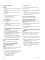
(2) Press the [F1] (SYSTEM LINE) key several times for
setting to the 1080 x 1920 or 720 x 1280.
F1
F2
F3
F4
DIAG
ALT
1-20
SYSTEM
LINE
SYSTEM MENU
1080/59.94i 422 YPbPr HDCAM-SR
LINE
1080
SYSTEM [F1]SYSTEM
1080
[F2]SYSTEM
SCAN MODE Interlace
SCAN
[F3]SYSTEM
FRAME
29.97Hz
720
SYSTEM [F4]SYSTEM SIGNAL MODE 422
FRAME
[F6]FRAME CONVERT
1080/59.94i
1080
SYSTEM [F7]ACTIVE LINE
[F8]CANCEL
[F9]Exec
of
Reset
VTR Sys
SIGNAL
(STOP & STANDBY OFF/EJECT)
REC FRAME ACTIVE CANCEL EXEC
FORMAT CNVERT LINE
F5
F6
F7
F8
EXIT
F9 F10
SRW-5000/5500
(3) Press the [F2] (SYSTEM SCAN) key several times
for setting to the Interlace, Progressive or PsF (Progressive Segmented Frame).
F1
F2
F3
F4
DIAG
ALT
SYSTEM
LINE
SYSTEM MENU
1080/59.94i 422 YPbPr HDCAM-SR
LINE
1080
SYSTEM [F1]SYSTEM
Interlace
[F2]SYSTEM
SCAN MODE Interlace
SCAN
[F3]SYSTEM
FRAME
29.97Hz
PsF
Progressive SIGNAL MODE 422
SYSTEM [F4]SYSTEM
FRAME
[F6]FRAME CONVERT
1080/59.94i
1080
SYSTEM [F7]ACTIVE LINE
[F8]CANCEL
[F9]Exec
of
Reset
VTR Sys
SIGNAL
(STOP & STANDBY OFF/EJECT)
REC FRAME ACTIVE CANCEL EXEC
FORMAT CNVERT LINE
F5
F6
F7
F8
(6) Press the [F6] (FRAME CONVERT) key several
times to set the image format of the format converter
output.
n
This item can be set when the option HKSR-5001 is
installed.
F1
SYSTEM
LINE
F2
SYSTEM
SCAN
EXIT
F3
F9 F10
F4
DIAG
(4) Press the [F3] (SYSTEM FRAME) key several times
to set the frame rate.
F1
SYSTEM
LINE
F2
SYSTEM
SCAN
F3
F4
DIAG
SYSTEM
FRAME
SYSTEM
SIGNAL
SYSTEM MENU
1080/59.94i 422 YPbPr HDCAM-SR
23.98Hz
[F1]SYSTEM
LINE
1080
24Hz
[F2]SYSTEM SCAN MODE Interlace
25Hz
[F3]SYSTEM FRAME
29.97Hz
[F4]SYSTEM
SIGNAL MODE 422
29.97Hz
30Hz
[F6]FRAME
CONVERT
1080/59.94i
50Hz
[F7]ACTIVE LINE
1080
59.94Hz
[F8]CANCEL [F9]Exec of Reset VTR Sys
(STOP & STANDBY OFF/EJECT)
REC FRAME ACTIVE CANCEL EXEC
FORMAT CNVERT LINE
EXIT
ALT
F5
F6
F7
F8
F1
F9 F10
F3
(5) Press the [F5] (REC FORMAT) key several times to
set the recording format (HDCAM-SR, HDCAM or
AUTO).
F4
DIAG
ALT
F1
F2
F3
F4
DIAG
ALT
SRW-5000/5500
SYSTEM
LINE
SYSTEM
SIGNAL
REC FRAME ACTIVE CANCEL EXEC
FORMAT CNVERT LINE
F5
F6
F7
F8
EXIT
F9 F10
(7) Press the [F7] (ACTIVE LINE) key several times for
setting the active line to 1080 or 1035.
n
This becomes effective only when the VTR is set to
4:2:2 1080 x 1920 Interlace 29.97 or 30 frames.
F2
ALT
SYSTEM
FRAME
SYSTEM MENU
1080/59.94i 422 YPbPr HDCAM-SR
1080/60i
[F1]SYSTEM
1080
1080/59.94i LINE
[F2]SYSTEM SCAN MODE Interlace
1080/50i
[F3]SYSTEM FRAME
29.97Hz
1080/30PsF SIGNAL MODE 422
[F4]SYSTEM
[F1080/29PsF
1080/25PsF CONVERT
[F6]FRAME
1080/59.94i
[F7]ACTIVE
1080
1080/24PsF LINE
[F8]CANCEL
[F9]Exec
of
Reset
VTR Sys
1080/23.98PsF
(STOP & STANDBY OFF/EJECT)
SYSTEM
LINE
SYSTEM MENU
1080/59.94i 422 YPbPr HDCAM-SR
1080
SYSTEM [F1]SYSTEM LINE
SCAN [F2]SYSTEM SCAN MODE Interlace
[F3]SYSTEM FRAME
29.97Hz
SYSTEM [F4]SYSTEM SIGNAL MODE 422
FRAME OFF
[F6]FRAME
CONVERT
1080/59.94i
1080
LINE
1080
SYSTEM [F7]ACTIVE
1035
[F8]CANCEL
[F9]Exec
of
Reset
VTR Sys
SIGNAL
(STOP & STANDBY OFF/EJECT)
REC FRAME ACTIVE CANCEL EXEC
FORMAT CNVERT LINE
F5
F6
F7
F8
EXIT
F9 F10
SYSTEM MENU
1080/59.94i
422 YPbPr
HDCAM-SR
SYSTEM
SCAN [F2]SYSTEM SCAN MODE Interlace
[F3]SYSTEM FRAME
29.97Hz
SYSTEM [F4]SYSTEM SIGNAL MODE 422 YPbPr
[F4]SYSTEM
REC
FORMAT
HDCAM-SR
FRAME HDCAM-SR
[F6]FRAME
CONVERT
--- N/A --HDCAM
LINE
OFF
SYSTEM [F7]ACTIVE
AUTO
SIGNAL [F8]CANCEL [F9]Exec of Reset VTR Sys
(STOP & STANDBY OFF/EJECT)
REC FRAME ACTIVE CANCEL EXEC
FORMAT CNVERT LINE
F5
F6
F7
F8
EXIT
F9 F10
1-21
3. Check the setting
Check that the content of system setting performed after
saving is displayed with white characters in the first line of
the system menu. Check further that the items to be
updated from the current system setting are displayed with
yellow characters to the right of respective setting items.
n
The faint white characters in the first line of the system
menu mean that a combination of unsettable system items
is selected.
Recheck and re-set the item shown with faint yellow
characters to the right of the item, etc. referring to Section
1-11-3.
Unsettable system status
(faint white characters)
F1
F2
F3
F4
DIAG
ALT
SYSTEM
LINE
SYSTEM MENU
1080/25PsF 422 YPbPr AUTO
1080
SYSTEM [F1]SYSTEM LINE
[F2]SYSTEM
SCAN MODE PsF
SCAN
[F3]SYSTEM FRAME
25Hz
SYSTEM [F4]SYSTEM SIGNAL MODE 422 YPbPr
[F5]SYSTEM
REC
FORMAT
AUTO
FRAME
[F6]FRAME CONVERT
444 1080/30PsF
1080
SYSTEM [F7]ACTIVE LINE
[F8]CANCEL
[F9]Exec
of
Reset
VTR Sys
SIGNAL
(STOP & STANDBY OFF/EJECT)
REC FRAME ACTIVE CANCEL EXEC
FORMAT CNVERT LINE
F5
F6
F7
F8
4. Storing the settings
(1) Press the [F9] (EXEC) key.
. The message “Are You Sure?” is displayed.
F1
F2
F3
F4
DIAG
ALT
SYSTEM
LINE
SYSTEM MENU
1080/59.94i 422 YPbPr HDCAM-SR
LINE
1080
SYSTEM [F1]SYSTEM
!
A r e Y oSCAN
u S u rMODE
e?
[F2]SYSTEM
Interlace
SCAN
[F3]SYSTEM FRAME
29.97Hz
I
f
y
o
u
p
r
e
s
s
[
F
9
]
a
g
a
i
n
SIGNAL MODE 422
SYSTEM [F4]SYSTEM
then EXECUTE.
FRAME
[F6]FRAME
CONVERT
1080/59.94i
Or press [F8] to CANCEL
.
1080
SYSTEM [F7]ACTIVE LINE
[F8]CANCEL
[F9]Exec
of
Reset
VTR Sys
SIGNAL
(STOP & STANDBY OFF/EJECT)
REC FRAME ACTIVE CANCEL EXEC
FORMAT CNVERT LINE
F5
F6
F7
F8
EXIT
F9 F10
(2) Press the [F9] (EXEC) key again.
. The message “SYSTEM REBOOTING......” is
displayed.
. On completing the store of the settings, the system is
restarted automatically.
EXIT
F9 F10
Unselectable item
(faint yellow characters)
F1
F2
F3
F4
DIAG
ALT
SYSTEM
LINE
SYSTEM MENU
1080/59.94i 422 YPbPr HDCAM-SR
1080
SYSTEM [F1]SYSTEM LINE
SCAN [F2]SYSTEM SCAN MODE Interlace
[F3]SYSTEM FRAME
29.97Hz
SIGNAL MODE 422
SYSTEM [F4]SYSTEM
!
S
Y
S
T
E
M
R
E
B
O
O
T
I
N
G
......
FRAME [F5]SYSTEM REC FORMAT
[F6]FRAME
Wait CONVERT
a moment.
1080
SYSTEM [F7]ACTIVE LINE
SIGNAL [F8]CANCEL [F9]Exec of Reset VTR Sys
(STOP & STANDBY OFF/EJECT)
REC FRAME ACTIVE CANCEL EXEC
FORMAT CNVERT LINE
F5
F6
F7
F8
EXIT
F9 F10
(3) Check that the system is restarted, and turn OFF the
POWER switch and turn ON again.
1-22
SRW-5000/5500
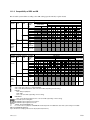
1-11-3. Compatibility of REC and PB
The selectable systems differ according to the VTR settings (operation mode) or option boards.
System setting (Operation mode)
SYSTEM SYSTEM SYSTEM SYSTEM
(FRAME)
SIGNAL LINE
SCAN
FREQ
[Hz]
23.98
PsF
4:2:2
1080
24
(YPbPr)
25
29.97
30
Interlace 25
29.97
30
Progressive 50*1
720
59.94*1
23.98,
PsF
4:4:4
1080
24, 25,
(RGB)
29.97, 30
(HKSRInterlace 25,
5003)
29.97, 30
System setting (Operation mode)
SYSTEM SYSTEM SYSTEM SYSTEM
(FRAME)
SCAN
SIGNAL LINE
FREQ
[Hz]
23.98
PsF
4:2:2
1080
24
(YPbPr)
25
29.97
30
Interlace 25
29.97
30
Progressive 50*1
720
59.94*1
23.98,
PsF
4:4:4
1080
24, 25,
(RGB)
29.97, 30
(HKSRInterlace 25,
5003)
29.97, 30
Digital BETACAM
Interlace
(HKSR-5002)
NTSC
PAL
23.98
24
PsF
25
Tape format which can be played back
HDCAM
1080 4:2:2
PsF
30
24
25
29.97
23.98
25
Interlace
29.97
30
Tape format which can be played back
HDCAM-SR
1080 4:4:4
720 4:2:2
1080 4:2:2
Progressive (HKSR-5003)
Interlace
30
29.97
29.97
25
30 50*1 59.94*1 PsF Interlace
*2
*2
*2
*2
Video, audio, time code: Normal playback
Video, audio, time code: 0.1 % off-speed playback
Video, audio: Off-speed playback, Time code: Convertible (depending on menu setting)
HDCAM:
Video: Off-speed playback
Audio: Mute
Time code: Convertible (depending on menu setting)
HDCAM-SR:
Video, audio: Off-speed playback, Time code: Convertible (depending on menu setting)
Unselectable system setting item
The HD SDI outoput signal becomes Interlace.
The HD SDI outoput signal becomes PsF.
*1
720/50P, 59.94P: HDCAM-SR only
*2
It is common the case playback a HDCAM-SR formatted tape with 4:2:2/1080 video date while system setting is 4:2:2/1080.
RGB 4:4:4: HDCAM-SR 1080 only
Tapes with different sampling method cannot be played back (4:4:4/4:2:2).
SRW-5000/5500
1-23
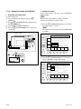
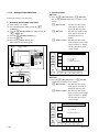
1-11-4. Setting to Store Meta Data
Perform the setting to store meta data.
1. Activating the meta data setup menu
(1) Turn on the power switch.
(2) Press the DIAG button while pressing the [SFT]
(SHIFT) key.
(3) Press the [F8] (MAINT EXEC) key while pressing the
[SFT] (SHIFT) key.
(4) Press the [F9] (OTHERS CHECK) key.
(5) Press the [ALT] key.
(6) Press the [F1] (META DATA) key.
The format selection menu appears.
5 [F1] 1 [SFT] + DIAG
SFT
F1
2 [SFT] + [F8]
F3
F4
DIAG
F5
F6
F7
F8
4 [ALT]
F3
F4
F9 F10
3 [F9]
META DATA MENU SELECT
F1
F2
F2
ALT
2. Format selection
SRW-5500
(1) Press the [F2] (HDCAM-SR) key, [F3] (HDCAM)
key, or [F4] (DOWN CONV.) key according to your
system.
[F2] (HDCAM-SR):
The meta data line setting
menu appears. Perform “3.
Setting the meta data line”.
[F3] (HDCAM):
The meta data packet setting
menu appears. Perform “5.
Setting the meta data 3
packet”.
[F4] (DOWN CONV.): The meta data line setting
menu of down convert output
appears. Perform “7. Setting
the meta data line of down
convert output”.
HDCAM
-SR
SELECT FORMAT
F2 : HDCAM-SR
F3 : HDCAM
F4 : DOWN CONV. OUT
HDCAM
DOWN
CONV.
EXIT
DIAG
ALT
F5
F6
F7
F8
F9
F10
SRW-5000
(1) Press the [F2] (HDCAM-SR) key, or [F4] (DOWN
CONV.) key according to your system.
[F2] (HDCAM-SR):
The meta data line setting
menu appears. Perform “3.
Setting the meta data line”.
[F4] (DOWN CONV.): The meta data line setting
menu of down convert output
appears. Perform “7. Setting
the meta data line of down
convert output”.
META DATA MENU SELECT
F1
F2
HDCAM
-SR
SELECT FORMAT
F2 : HDCAM-SR
F3
F4
F4 : DOWN CONV. OUT
DOWN
CONV.
EXIT
DIAG
ALT
1-24
F5
F6
F7
F8
F9
F10
SRW-5000/5500
In selecting [F2] (HDCAM-SR) on SRW-5000,
or SRW-5500
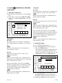
3. Setting the meta data line
(1) Move the cursor to the item to be set using the [(]/[)]
keys.
(2) Perform the line setting using the [F8] (PLUS)/[F9]
(MINUS) keys, MULTI CONTROL knob, or the [&]/
[*] keys.
F1
NVRAM
CTL
HDCAM-SR META DATA LINE SELECT
Meta Data 1(1080) : Line 09
Meta Data 2(1080) : Line 19
Meta Data 3(1080) : Line 20
F2
Meta Data 1(720)
Meta Data 2(720)
Meta Data 3(720)
F3
: Line 09
: Line 19
: Line 20
F4
DIAG
ALT
F5
F6
F7
PLUS
MINUS
EXIT
F8
F9
F10
1080 system
Recording
Records the line that is set by Meta Data 1 (1080), Meta
Data 2 (1080) or Meta Data 3 (1080) as a non-compressed
line.
n
This is not affected by Meta Data 1 (720), Meta Data 2
(720) or Meta Data 3 (720).
Playback
Plays back non-compressed lines recorded in a tape
(1080i) and outputs them.
n
They are not affected by Meta Data 1 (1080), Meta Data 2
(1080) or Meta Data 3 (1080) and Meta Data 1 (720), Meta
Data 2 (720) or Meta Data 3 (720).
720 system
Recording
Records the line that is set by Meta Data 1 (720), Meta Data
2 (720) or Meta Data 3 (720) as a non-compressed line.
n
This is not affected by Meta Data 1 (1080), Meta Data 2
(1080) or Meta Data 3 (1080).
Playback
Plays back non-compressed lines recorded in a tape (720)
and outputs them.
n
They are not affected by Meta Data 1 (1080), Meta Data 2
(1080) or Meta Data 3 (1080) and Meta Data 1 (720), Meta
Data 2 (720) or Meta Data 3 (720).
When performing 720 to 1080 conversion with HKSR5001, the non-compressed lines are multiplexed sequentially with the HKSR-5001 1080 output as non-compressed
lines according to the Meta Data 1 (1080)/Meta Data 2
(1080)/Meta Data 3 (1080) setting.
n
They are not affected by Meta Data 1 (720), Meta Data 2
(720) or Meta Data 3 (720).
4. Storing the settings
(1) Press the [F1] (NVRAM CTL) key.
(2) Select “SAVE ALL DATA” using the [(]/[)] keys,
and press the [F10] (EXIT) key.
. The changed data is written in the NV-RAM, and the
menu returns to the META DATA SETUP menu.
. When the changed data is not to be saved, select “NO
OPERATION”, and press the [F10] (EXIT) key.
OTHERS CHECK
F1
NVRAM CONTROL
NO OPERATION
SAVE ALL DATA
F2
F3
When performing 1080 to 720 conversion with HKSR5001, the non-compressed lines are multiplexed sequentially with the HKSR-5001 720 output as non-compressed
lines according to the Meta Data 1 (720)/Meta Data 2
(720)/Meta Data 3 (720) setting.
n
They are not affected by Meta Data 1 (1080), Meta Data 2
(1080) or Meta Data 3 (1080).
SRW-5000/5500
If you save the data,
turn off and on the VTR.
F4
EXIT
DIAG
ALT
F5
F6
F7
F8
F9
F10
(3) Press the [F10] (EXIT) key several times to return to
the OTHERS CHECK menu. When setting input/
output phases continuously, proceed to Section 1-11-5.
(4) Turn OFF the POWER switch and turn ON again.
1-25
In selecting [F3] (HDCAM) on SRW-5500
5. Setting the meta data 3 packet
(1) Move the cursor to the item to be set using the [(]/[)]/
[&]/[*] keys.
(2) Perform the line setting using the [F8] (PLUS)/[F9]
(MINUS) keys or the MULTI CONTROL knob.
Window Description
ANC1 to ANC3:
Ancillary data
LINE1, LINE2 (D): Line number (decimal)
DID (H):
Data ID (hexadecimal)
SDID (H):
Secondary data ID (hexadecimal)
F1
NVRAM
CTL
HDCAM VANC PACKET SELECT
LINE1
(D)
000
000
000
F2
ANC1
ANC2
ANC3
F3
LINE2
(D)
000
000
000
DID
(H)
00
00
00
SDID
(H)
00
00
00
F4
PLUS
DIAG
MINUS
EXIT
6. Storing the settings
(1) Press the [F1] (NVRAM CTL) key.
(2) Select “SAVE ALL DATA” using the [(]/[)] keys,
and press the [F10] (EXIT) key.
. The changed data is written in the NV-RAM, and
the menu returns to the META DATA SETUP
menu.
. Or select either of the following items, and then
press the [F10] (EXIT) key.
NO OPERATION:
Changed data is not saved.
ALL DATA PREVIOUS: To return the data to the
previous data.
RESET ALL DATA:
To reset the NV-RAM to
the factory setting.
OTHERS CHECK
F1
NVRAM CONTROL
NO OPERATION
SAVE ALL DATA
ALL DATA PREVIOUS
RESET ALL DATA
F2
F3
If you save the data,
turn off and on the VTR.
F4
ALT
F5
F6
F7
F8
F9
F10
EXIT
DIAG
ALT
F5
F6
F7
F8
F9
F10
(3) Press the [F10] (EXIT) key several times to return to
the OTHERS CHECK menu. When setting input/
output phases continuously, proceed to Section 1-11-5.
(4) Press the [F10] (EXIT) key several times to return to
the HOME menu.
n
When playing back an HDCAM tape with meta data
recorded, the meta data cannot be multiplexed with FC
OUT.
1-26
SRW-5000/5500
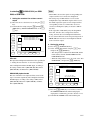
In selecting [F4] (DOWN CONV.) on SRW5000, or SRW-5500
7. Setting the meta data line of down convert
output
(1) Move the cursor to the item to be set using the [(]/[)]
keys.
(2) Perform the line setting using the [F8] (PLUS)/[F9]
(MINUS) keys, MULTI CONTROL knob, or the [&]/
[*] keys.
F1
NVRAM
CTL
DC OUTPUT META DATA LINE SELECT
Meta Line1(HDCAM-SR) : OFF
Meta Line2(HDCAM-SR) : DC Line 18
Meta Line3(HDCAM-SR) : DC Line 19
F2
m
. When OFF is selected, the signal of corresponding noncompressed line is not converted or multiplexed.
. The setting range is OFF and Line 9 to 22, but the
multiplexable range with NTSC output is Line 12 to 19.
For NTSC output, the signals of non-compressed lines
corresponding to Line 9 to 11/Line 20 to 22 are not
converted or multiplexed. (They are treated as OFF in
the unit.)
. If the output line of SD VITC (set by the Setup Menu
Items 611, 612, 617, 618) overlaps meta data line
setting, the meta data is not multiplexed with the line.
. In case of the Pull Down conversion processing mode of
HKSR-5001, the meta data is not multiplexed with the
down-conversion output.
F3
F4
DIAG
ALT
F5
F6
F7
PLUS
MINUS
EXIT
F8
F9
F10
EE mode
The input data multiplexed with the three lines specified in
“3. Setting the meta data line” is converted sequentially
and is multiplexed with the SD SDI output, according to
the settings of Meta Line 1 (HDCAM-SR), Meta Line 2
(HDCAM-SR), and Meta Line 3 (HDCAM-SR).
HDCAM-SR playback mode
The data of the three non-compressed lines stored on the
tape is converted sequentially and is multiplexed with the
SD SDI output, according to the settings of Meta Line 1
(HDCAM-SR), Meta Line 2 (HDCAM-SR), and Meta
Line 3 (HDCAM-SR).
8. Storing the settings
(1) Press the [F1] (NVRAM CTL) key.
(2) Select “SAVE ALL DATA” using the [(]/[)] keys,
and press the [F10] (EXIT) key.
. The changed data is written in the NV-RAM, and the
menu returns to the DC OUTPUT META DATA
LINE SELECT menu.
. When the changed data is not to be saved, select “NO
OPERATION”, and press the [F10] (EXIT) key.
OTHERS CHECK
F1
NVRAM CONTROL
NO OPERATION
SAVE ALL DATA
F2
F3
If you save the data,
turn off and on the VTR.
F4
EXIT
DIAG
ALT
F5
F6
F7
F8
F9
F10
(3) Press the [F10] (EXIT) key several times to return to
the OTHERS CHECK menu. When setting input/
output phases continuously, proceed to Section 1-11-5.
(4) Turn OFF the POWER switch and turn ON again.
SRW-5000/5500
1-27
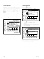
1-11-5. Input/Output Phase Settings
Perform phase settings for various inputs and outputs.
n
The phase setting procedure of SRW-5500 is the same as
that of SRW-5000.
1. Activating the phase set menu
When OTHERS CHECK menu is displayed:
(1) Press the [F2] (PHASE SET) key to display the
PHASE SET menu.
When a menu is not displayed:
(1) Turn on the power switch.
(2) Press the DIAG button while pressing the [SFT]
(SHIFT) key.
(3) Press the [F8] (MAINT EXEC) key while pressing the
[SFT] (SHIFT) key.
(4) Press the [F9] (OTHERS CHECK) key.
(5) Press the [ALT] key.
(6) Press the [F2] (PHASE SET) key to display the
PHASE SET menu.
5 [F2] 1 [SFT] + DIAG
2. Setting the input/output phase
(1) Press the [F2] (HD SDI OUT) key several times to set
the HD SDI output phase (OFF or _90H).
OFF: Outputs in the same phase as reference signal.
_90H: Outputs 90H (HD) ahead of reference signal.
F1
NVRAM
CTL
F2
HD SDI
OUT
F3
SD SDI
OUT
OTHERS CHECK
PHASE SETTING
F4
AU PB
OUT
DIAG
AUDIO
INPUT
ALT
F5
HD SDI OUTPUT ADV.
SD SDI OUTPUT ADV.
AUDIO PB OUTPUT ADV.
AUDIO INPUT DELAY
TC INPUT DELAY
AES/EBU &
ANALOG OUTPUT
LTC OUTPUT
TC
AES/AN
INPUT
OUT
F6
F7
: -90H
: -2H
: -1FRAME
: +1FRAME
: +1FRAME
: LINE
: LINE
LTC
OUT
F8
EXIT
F9
F10
(2) Press the [F3] (SD SDI OUT) key several times to set
the SD SDI output phase (OFF or _2H).
OFF: Outputs in the same phase as reference signal.
_2H: Outputs 2H (SD) ahead of reference signal.
F1
NVRAM
CTL
F2
HD SDI
OUT
F3
SD SDI
OUT
OTHERS CHECK
PHASE SETTING
SFT
F1
F2
2 [SFT] + [F8]
F3
F4
DIAG
ALT
F5
F6
F7
F8
4 [ALT]
1-28
F4
AU PB
OUT
DIAG
AUDIO
INPUT
ALT
F5
HD SDI OUTPUT ADV.
SD SDI OUTPUT ADV.
AUDIO PB OUTPUT ADV.
AUDIO INPUT DELAY
TC INPUT DELAY
AES/EBU &
ANALOG OUTPUT
LTC OUTPUT
TC
AES/AN
INPUT
OUT
: -90H
: -2H
: -1FRAME
: +1FRAME
: +1FRAME
: LINE
: LINE
LTC
OUT
EXIT
F9 F10
3 [F9]
F6
F7
F8
F9
F10
SRW-5000/5500
(3) Press the [F4] (AU PB OUT) key several times to set
the playback audio output phase (OFF or _1FRAME).
OFF:
Outputs in the same phase as reference
signal.
_1FRAME: Outputs one-frame ahead of reference
signal.
F1
NVRAM
CTL
OTHERS CHECK
(5) Press the [F6] (TC INPUT) key several times to set
the record time code input phase (OFF or +1FRAME).
OFF
Records in the same phase as reference
signal.
+1FRAME: Records with one-frame delay of reference signal.
F1
NVRAM
CTL
F2
HD SDI
OUT
F3
SD SDI
OUT
OTHERS CHECK
PHASE SETTING
F2
HD SDI
OUT
F3
SD SDI
OUT
F4
AU PB
OUT
DIAG
AUDIO
INPUT
ALT
F5
PHASE SETTING
HD SDI OUTPUT ADV.
SD SDI OUTPUT ADV.
AUDIO PB OUTPUT ADV.
AUDIO INPUT DELAY
TC INPUT DELAY
AES/EBU &
ANALOG OUTPUT
LTC OUTPUT
TC
AES/AN
INPUT
OUT
F6
F7
: -90H
: -2H
: -1FRAME
: +1FRAME
: +1FRAME
: LINE
: LINE
LTC
OUT
F8
EXIT
F9
F10
(4) Press the [F5] (AUDIO INPUT) key several times to
set the record audio input phase (OFF or +1FRAME).
OFF:
Records in the same phase as reference
signal.
+1FRAME: Records with one-frame delay of reference signal.
F1
NVRAM
CTL
F2
HD SDI
OUT
F3
SD SDI
OUT
OTHERS CHECK
F4
DIAG
AUDIO
INPUT
ALT
F5
AU PB
OUT
DIAG
AUDIO
INPUT
ALT
F5
SRW-5000/5500
F6
F7
: -90H
: -2H
: -1FRAME
: +1FRAME
: +1FRAME
: LINE
: LINE
LTC
OUT
F8
F6
F7
: LINE
: LINE
LTC
OUT
F8
EXIT
F9
F10
F1
NVRAM
CTL
F2
HD SDI
OUT
F3
SD SDI
OUT
OTHERS CHECK
PHASE SETTING
HD SDI OUTPUT ADV.
SD SDI OUTPUT ADV.
AUDIO PB OUTPUT ADV.
AUDIO INPUT DELAY
TC INPUT DELAY
AES/EBU &
ANALOG OUTPUT
LTC OUTPUT
TC
AES/AN
INPUT
OUT
TC
AES/AN
INPUT
OUT
: -90H
: -2H
: -1FRAME
: +1FRAME
: +1FRAME
(6) Press the [F7] (AES/AN OUT) key several times to
set the AES/EBU and ANALOG AUDIO output phase
(LINE, SD or FC).
LINE: Outputs in the same phase as the main line.
SD:
Outputs in the same phase as SD output.
FC:
Outputs in the same phase as FC output.
PHASE SETTING
F4
AU PB
OUT
HD SDI OUTPUT ADV.
SD SDI OUTPUT ADV.
AUDIO PB OUTPUT ADV.
AUDIO INPUT DELAY
TC INPUT DELAY
AES/EBU &
ANALOG OUTPUT
LTC OUTPUT
F9
F4
AU PB
OUT
EXIT
DIAG
AUDIO
INPUT
F10
ALT
F5
HD SDI OUTPUT ADV.
SD SDI OUTPUT ADV.
AUDIO PB OUTPUT ADV.
AUDIO INPUT DELAY
TC INPUT DELAY
AES/EBU &
ANALOG OUTPUT
LTC OUTPUT
TC
AES/AN
INPUT
OUT
F6
F7
: -90H
: -2H
: -1FRAME
: +1FRAME
: +1FRAME
: LINE
: LINE
LTC
OUT
F8
EXIT
F9
F10
1-29
(7) Press the [F8] (LTC OUT) key several times to set the
LTC output phase (LINE or FC).
LINE: Outputs in the same phase as the main line.
FC:
Outputs in the same phase as FC output.
F1
NVRAM
CTL
F2
HD SDI
OUT
F3
SD SDI
OUT
OTHERS CHECK
PHASE SETTING
F4
AU PB
OUT
DIAG
AUDIO
INPUT
ALT
F5
HD SDI OUTPUT ADV.
SD SDI OUTPUT ADV.
AUDIO PB OUTPUT ADV.
AUDIO INPUT DELAY
TC INPUT DELAY
AES/EBU &
ANALOG OUTPUT
LTC OUTPUT
TC
AES/AN
INPUT
OUT
F6
F7
: -90H
: -2H
: -1FRAME
: +1FRAME
: +1FRAME
: LINE
: LINE
LTC
OUT
F8
EXIT
F9
F10
3. Storing the settings
(1) Press the [F1] (NVRAM CTL) key.
(2) Select “SAVE ALL DATA” using the [(]/[)] keys,
and press the [F10] (EXIT) key.
. The changed data is written in the NV-RAM, and
the menu returns to the PHASE SET menu.
. Or select either of the following items, and then
press the [F10] (EXIT) key.
NO OPERATION:
Changed data is not saved.
ALL DATA PREVIOUS: To return the data to the
previous data.
RESET ALL DATA:
To reset the NV-RAM to
the factory setting.
1-11-6. Storing and Reading System Settings
in/from System Bank
Up to eight current system settings made by the SYSTEM
menu, META DATA SETUP menu, and PHASE SET
menu can be saved in the system bank of the unit with
respective titles. The settings can also be read from the
system bank as current settings.
The SYSTEM BANK menu is available for storing and
reading system settings in/from the system bank.
The settings saved in the system bank can also be stored in
a Memory Stick with the SYSTEM CARD BANK menu,
and read from the Memory Stick.
For titling the system bank, refer to Section 1-11-8.
For storing/reading the data saved in the system bank in/
from a Memory Stick, refer to Section 1-11-7.
n
SYSTEM BANK and SYSTEM CARD BANK menus are
available to store/copy data, but are not available to update
system settings.
1. System settings
Perform system settings using the SYSTEM menu, META
DATA SETUP menu, and PHASE SET menu referring to
the following.
. SYSTEM menu:
Section 1-11-1 (SRW-5000)
Section 1-11-2 (SRW-5500)
. META DATA SETUP menu:
Section 1-11-4
. PHASE SET menu:
Section 1-11-5
OTHERS CHECK
F1
NVRAM CONTROL
NO OPERATION
SAVE ALL DATA
ALL DATA PREVIOUS
RESET ALL DATA
F2
F3
F4
EXIT
DIAG
ALT
F5
F6
F7
F8
F9
F10
(3) Press the [F10] (EXIT) key several times to return to
the HOME menu.
1-30
SRW-5000/5500
2. Displaying SYSTEM BANK menu
(1) Press the DIAG button while pressing the [SFT]
(SHIFT) key with the HOME menu.
(2) Press the [F8] (MAINTE EXEC) key while pressing
the [SFT] (SHIFT) key.
(3) Press the [F9] (OTHERS CHECK) key.
(4) Press the [ALT] key.
(5) Press the [F5] (SYSTEM BANK) key to display the
SYSTEM BANK menu.
Window Description
The left item [C] shows the current settings, the right
items 1 to 8 show system bank data, and [F] shows
factory settings.
The item of lighting cursor bar shows the save origin,
and the item of blinking cursor bar shows the save
destination.
shows an item for title editing, etc.
Use the [&]/[*]/[(]/[)] keys to choose the item
pointed by .
3. Storing the settings in the system bank
n
No data can be written in the factory setting [F].
(1) Press the [F8] (DIRECTION) key with the SYSTEM
BANK menu, and choose direction.
The right cursor bar blinks.
(2) Position the blinking cursor bar at a bank number (1 to
8) to store the current settings using the [(]/[)] keys.
(3) Press the [F9] (COPY) key.
A confirmation message appears.
To cancel storing
Press the [CLR] (CLEAR) key while the confirmation
message is displayed.
(4) Press the [F9] (COPY) key while pressing the [SFT]
(SHIFT) key.
Storing the settings starts. The save origin title appears
at the save destination upon completion of the saving.
1 [SFT] + DIAG
To give or change a title after saving
Edit system bank titles referring to Section 1-11-8.
SFT
F1
F2
2 [SFT] + [F8]
F3
F4
DIAG
ALT
F5
F6
F7
F8
F9 F10
5 [F5]
3 [F9]
4 [ALT]
To protect the system bank after saving
(protection against wrong deletion)
Position at a bank number to be protected, and press the
[ALT] key.
Press the [F2] (PROTECT) key to light up a key mark to
the left of the bank number.
(5) Press the [F10] (EXIT) key several times to return to
the HOME menu.
CURRENT SYSTEM
F1
(Preset)
C
F2
F3
F4
DATA
DETAIL
EDIT
TITLE
DIAG
ALT
SRW-5000/5500
F5
F6
F7
SYSTEM BANK 1
1
2
3
4
5
6
7
8
F
(Preset)
(Preset)
(Preset)
(Preset)
(Preset)
(Preset)
(Preset)
(Preset)
(Preset)
DIRECTION
COPY
EXIT
F8
F9
F10
1-31
4. Reading the settings from the system bank
n
No data can be read from the system bank in the standby
mode or while a tape is loaded in the unit.
Eject the tape and confirm that the standby mode is set to
off before reading data.
(1) Press the [F8] (DIRECTION) key with the SYSTEM
BANK menu, and choose direction.
The left cursor bar blinks.
(2) Position the lighting cursor bar at a bank number (1 to
8) for reading with the [(]/[)] keys.
(3) Press the [F9] (COPY) key.
A confirmation message appears.
To cancel reading
Press the [CLR] (CLEAR) key while the confirmation
message is displayed.
(4) Press the [F9] (COPY) key while pressing the [SFT]
(SHIFT) key.
Upon completion of writing the setting to the current
system settings, the system is reset with a beep and the
unit restarts.
After the unit restarts, the title of the read bank number
appears at the left item [C].
n
If the system settings are updated after reading, the
title displayed at [C] remains unchanged.
1-11-7. Storing/Reading System Settings in/
from Memory Stick
The system settings saved in the system bank of the unit
can be stored in a Memory Stick with a title.
The system settings saved in a Memory Stick can also be
loaded to the system bank of the unit.
Data saving in and reading from a Memory Stick are
available with the SYSTEM CARD BANK menu.
For titling the system bank, refer to Section 1-11-8.
n
The system settings saved in the system bank are stored in
a Memory Stick as a file different from that in the VTR
bank (menu file).
1. Inserting Memory Stick.
(1) Open the lower control panel. (Refer to Section 1-12.)
(2) Insert a Memory Stick to store or read the system
settings into the Memory Stick slot.
n
If another Memory Stick is already inserted, press the
eject button at the right of the Memory Stick slot to
eject it.
(5) Press the [F10] (EXIT) key several times to return to
the HOME menu.
1-32
SRW-5000/5500
2. Displaying SYSTEM CARD BANK menu
(1) Press the DIAG button while pressing the [SFT]
(SHIFT) key with the HOME menu.
(2) Press the [F8] (MAINTE EXEC) key while pressing
the [SFT] (SHIFT) key.
(3) Press the [F9] (OTHERS CHECK) key.
(4) Press the [ALT] key.
(5) Press the [F6] (SYSTEM CARD) key to display the
SYSTEM CARD BANK menu.
Window Description
The right item shows the data of the unit, [C] shows
current settings, 1 to 8 show system bank data, and [F]
shows factory settings.
The left item shows Memory Stick data, and 1 to 8
show system bank data of the Memory Stick.
The item of the lighting cursor bar shows the save
origin, and the item of the blinking cursor bar shows
the save destination.
shows an item for title editing, etc.
Use the [&]/[*]/[(]/[)] keys to choose the item
pointed by .
1 [SFT] + DIAG
SFT
F1
F2
2 [SFT] + [F8]
F3
F4
DIAG
ALT
F5
F6
F7
4 [ALT]
F1
FORMAT
CARD
F3
DATA
DETAIL
SRW-5000/5500
3 [F9]
SYS CARD BANK 1
(Preset)
(Preset)
(Preset)
(Preset)
(Preset)
(Preset)
(Preset)
(Preset)
1
2
3
4
5
6
7
8
EDIT SELECT DIRECTITLE
ALL
TION
DIAG
ALT
F9 F10
5 [F6]
F2
F4
F8
F5
F6
F7
F8
CURRENT SYSTEM
C
1
2
3
4
5
6
7
8
F
(Preset)
(Preset)
(Preset)
(Preset)
(Preset)
(Preset)
(Preset)
(Preset)
(Preset)
(Preset)
COPY
EXIT
F9
F10
1-33
3. Memory Stick format
m
. No Memory Stick can be used unless it is formatted by
the unit.
Format a Memory Stick to be used before storing the
system settings.
. When a Memory Stick is formatted, its data is cleared
completely.
(1) Press the [F1] (FORMAT CARD) key with the
SYSTEM CARD BANK menu.
A confirmation message appears.
To cancel formatting
Press the [CLR] (CLEAR) key while the confirmation
message is displayed.
(2) Press the [F1] (FORMAT CARD) key while pressing
the [SFT] (SHIFT) key.
Formatting the Memory Stick starts and a directory is
created.
4. Loading the settings from the system bank to
a Memory Stick
(1) Insert a Memory Stick into the slot of the unit, and
display the SYSTEM CARD BANK menu.
(2) Press the [F8] (DIRECTION) key with the SYSTEM
CARD BANK menu, and choose direction.
The left cursor bar blinks.
(3) Press the [*] key to move to the right (unit data
side), and position the lighting cursor bar at the item to
be stored in a Memory Stick using the [(]/[)] keys.
To store current system settings in a Memory
Stick
Position the lighting cursor bar at the item [C].
To store eight pieces of system bank data
collectively in a Memory Stick
Press the [F7] (SELECT ALL) key.
n
If any protected bank number exists in the system bank, the
[F7] (SELECT ALL) key cannot be selected.
To cancel storing
Press the [CLR] (CLEAR) key while the confirmation
message is displayed.
(6) Press the [F9] (COPY) key while pressing the [SFT]
(SHIFT) key.
Storing the settings starts. The title of the save origin
appears at the save destination (Memory Stick side)
upon completion of the storing.
To give or change a title after saving
Edit system bank titles referring to Section 1-11-8.
To protect the system bank after saving
(protection against wrong deletion)
Position at a bank number to be protected, and press the
[ALT] key.
Press the [F2] (PROTECT) key to light up a key mark to
the left of the bank number.
(7) Press the [F10] (EXIT) key several times to return to
the HOME menu.
5. Loading the settings from Memory Stick to the
system bank
n
When updating the current system settings to those stored
in a Memory Stick, eject the tape and confirm that the
standby mode is set to off before reading the data.
(1) Insert the Memory Stick storing the data to be loaded
into the slot, and display the SYSTEM CARD BANK
menu.
(2) Press the [F8] (DIRECTION) key with the SYSTEM
CARD BANK menu, and choose direction.
The right cursor bar blinks.
(3) Press the [&] key to move to the left (Memory Stick
side), and position the lighting cursor bar at the bank
number of the save origin (system bank of Memory
Stick) using the [(]/[)] keys.
(4) Press the [&] key to move to the left (Memory Stick
side), and position the blinking cursor bar at the bank
number of the save destination (system bank of
Memory Stick) using the [(]/[)] keys.
(5) Press the [F9] (COPY) key.
A confirmation message appears.
1-34
SRW-5000/5500
To collectively read eight pieces of system bank
data stored in a Memory Stick
Press the [F7] (SELECT ALL) key.
n
If any protected bank number exists in the system bank, the
[F7] (SELECT ALL) key cannot be selected.
(4) Press the [*] key to move to the right (unit data
side), and position the blinking cursor bar at the bank
number of the save origin (unit system bank) using the
[(]/[)] keys.
To update the current system settings
Position the blinking cursor bar at the item [C].
(5) Press the [F9] (COPY) key.
A confirmation message appears.
To cancel reading
Press the [CLR] (CLEAR) key while the confirmation
message is displayed.
(6) Press the [F9] (COPY) key while pressing the [SFT]
(SHIFT) key.
Reading the settings starts, and the title of the save
origin appears at the save destination (unit data side)
upon completion of the reading.
1-11-8. Editing Titles of the System Bank
Titling the system bank of the unit with the SYSTEM
BANK menu or SYSTEM CARD BANK menu enables to
manage the system setting data with a title.
n
A title that is read last is displayed at the current system
settings of the unit ([C] in the SYSTEM BANK menu or
SYSTEM CARD BANK menu).
If the system settings are updated after reading with the
SYSTEM menu, META DATA SETUP menu or PHASE
SET menu, the title shown at [C] remains unchanged.
Therefore, a bank number with the same title as that shown
at [C] does not ensure that the data is identical to the
current system settings.
(1) Display the SYSTEM BANK menu or SYSTEM
CARD BANK menu.
(2) Position at the item for editing title using the [&]/
[*]/[(]/[)] keys.
(3) Press the [F6] (EDIT TITLE) key.
A window for editing text opens.
CURRENT SYSTEM
F1
F2
F3
To update the current system settings
Upon completion of writing the setting to the current
system settings, the system is reset with a beep and the unit
restarts.
After the unit restarts, the title of the read bank number
appears at the right item [C].
(7) Press the [F10] (EXIT) key several times to return to
the HOME menu.
SRW-5000/5500
F4
DATA
DETAIL
ALT
(Preset)
C
1 (Preset)
CURRENT SYSTEM
TITLE EDIT
2 (Preset)
3 (Preset)
4
(Preset)
(Preset)_
[||||||||||||||||||||||||||||||||||]
5 (Preset)
6 (Preset)
ABCDEFGHIJKLMNOPQRSTUVWXYZ
7 (Preset)
a b c d e f g h i j k l m n o8
p q(Preset)
rstuvwxyz
0123456789[]()<>
+_*=!?:;|
F@(Preset)
$#%&,."\^_'/~`{}
EDIT
TITLE
DIAG
F5
SYSTEM BANK 1
F6
F7
HD1D2CAM
DIRECTION
COPY
EXIT
F8
F9
F10
(4) Type characters.
For typing characters, refer to 4-1-6 of the operation
manual.
(5) Press the [F10] (SAVE/EXIT) key.
The entered title is fixed.
1-35
1-11-9. Checking Saved System Bank Data in
Detail
The data stored in the system bank is the settings of the
SYSTEM menu, META DATA SETUP menu, and
PHASE SET menu.
Details of the settings and the current system settings of
the unit can be checked in the following procedure.
n
Refer to the following for the setting of each menu.
. SYSTEM menu:
Section 1-11-1 (SRW-5000)
Section 1-11-2 (SRW-5500)
. META DATA SETUP menu:
Section 1-11-4
. PHASE SET menu:
Section 1-11-5
(1) Display the SYSTEM BANK menu or SYSTEM
CARD BANK menu.
(2) Position at the item to be checked in detail using the
[&]/[*]/[(]/[)] keys.
(3) Press the [F4] (DATA DETAIL) key to display details
of the selected system bank data.
Setting items different from the current system settings
of the unit are displayed with yellow characters.
Further, setting items that cannot be loaded to the
current system settings due to options are displayed
with red characters.
n
The system bank data including setting item with red
characters cannot be loaded to the current system
settings, but can be copied (between Memory Stick
and system bank of the unit).
F1
F2
F3
F4
The data saved in a Memory Stick on the unit is also
available for other SRW-5000/5500.
However, the data cannot be loaded to the current settings
of another unit in some cases due to options or other
reasons.
If the data cannot be read, check the details of the system
bank data of the unit from which the data is read.
(Refer to Section 1-11-9.)
m
. The system bank data saved in SRW-5500 whose
recording format is HDCAM cannot be loaded to the
current settings of SRW-5000.
. The system bank data saved in SRW-5500 whose
recording format is AUTO can be loaded to the current
settings of SRW-5000.
In this case, “AUTO” is displayed on the sub LCD, but it
is impossible to record on the HDCAM formatted tape.
FORMAT <SYS CARD BANK 4> : (Preset)
CARD
SYSTEM
: 1080 23.98PsF 422 YPbPr
REC FORMAT : AUTO
FC FORMAT
: 422 1080 59.94i
ACTIVE LINE
: OFF
HDCAM-SR META (1080) : 09/19/20
HDCAM-SR META (720) : 09/19/20
HDCAM META ANC1 : 000/000/00/00
HDCAM META ANC2 : 000/000/00/00
HDCAM META ANC3 : 000/000/00/00
DATA
F4 : NEXT PAGE
DETAIL
EDIT SELECT DIRECTITLE
ALL
TION
DIAG
ALT
1-11-10. Compatibility of System Bank Data
F5
F6
F7
F8
COPY
EXIT
F9
F10
(4) Press the [F4] (DATA DETAIL) key continuously to
display further detailed data and to return to the
SYSTEM BANK menu or SYSTEM CARD BANK
menu.
1-36
SRW-5000/5500
1-12. Opening/Closing the Lower Control
Panel
Close the Lower Control Panel
Open the Lower Control Panel
1. While lifting the outer stays by the forefinger, close
the lower control panel as shown in the figure.
2. Reinstall the lock plates removed in step 1 of the
opening procedure.
1. If the lock plates are attached, remove the two screws
and remove the lock plates.
n
When no lock plate is attached at the start, this operation is
not necessary.
Lock plate
B3 x 6
Lock plate
Outer stay
2. After pressing the unlock buttons, open the lower
control panel in the arrow direction.
n
The inclination of the lower control panel can be adjusted
to five steps (about 18d each time) between vertical and
horizontal.
Unlock button
Unlock button
Lower control panel
SRW-5000/5500
1-37
1-13. Reference System
For each reference signal of this unit, either of an external reference video signal from the REF. INPUT 1
connector or input video signal from the HD SDI INPUT A connector is automatically selected according
to the setting of setup menu ITEM-005, and the operation mode (PB/EDIT/REC) of this unit. (Refer to the
table 1-13-1 below.)
n
When the setup menu ITEM-005 is set to “external”, be sure to input the external reference video signal
to the REF. INPUT 1 connector.
The record might not be correctly done.
Alarm Display for Video Input Signal and Reference Signal
Blink of the STOP button
The button blinks when the reference signal is not locked to an input video signal.
(This function can be canceled in the setup menu ITEM-102.)
. When the setup menu ITEM-005 is set to “input”:
The STOP button blinks when the signal is not input to the HD SDI INPUT A connector or when a
different signal from the selected system is input.
. When the setup menu ITEM-005 is set to “external”:
The STOP button blinks when no reference signal is input to REF. INPUT 1 connector or when the
different reference video signal (REF. INPUT 1) from the system is input.
. When the setup menu ITEM-005 is set to “auto”:
The STOP button blinks in either of the following cases.
In the REC/EDIT mode, when no signal is input to the HD SDI INPUT A connector or when a different
signal from the selected system is input.
In the PB mode, when no reference signal is input to REF. INPUT 1 connector or when no reference
video signal (REF. INPUT 1) is input.
Table 1-13-1. Reference System
ITEM-005 setting
external
Operation mode
PB/EDIT/REC
Selected reference signal
1-38
REF. INPUT 1
auto
PB
EDIT
input
REC
PB/EDIT/REC
HD SDI INPUT A
SRW-5000/5500
1-14. Settings when Editor is Connected
1-14-1. Settings for Time Code
To set the TIME CODE, use the TC menu in the function menu.
Set the TIME CODE as follows when the editor or the VTR with edit function is connected.
Button
Item
Setting
F6
REGENE SOURCE
int-L
F7
TCG MODE
preset
F8
RUN MODE
free
1-14-2. VTR Constant Values Settings of Editor
Set the VTR constant values according to the table 1-14-2 below when the editor which needs the setting
of VTR constant values is connected.
Table 1-14-2. VTR Constant Values Settings of Editor (Standard Value/Hexadecimal)
SRW-5000
VTR CONSTANT 1
59.94i, 60i, 60P,
29.97PsF, 30PsF
50i, 50P, 25PsF
24PsF, 23.98PsF
VTR CONSTANT 2
1
2
3
Data No.
4
5
20
A0
00
96
07
07
03
8A
0D
06
00
00
21
22
A0
A0
00
00
7D
78
07
07
07
07
03
03
8A
8A
0D
0D
06
06
00
00
00
00
Frame rate
6
7
8
1
2
3
Data No.
4
5
6
7
8
80
3D
FF
5A
80
80
3B
3B
FF
FF
4B
4B
6
7
8
SRW-5500
VTR CONSTANT 1
1
2
3
Data No.
4
5
6
7
8
1
2
3
Data No.
4
5
20
A1
00
96
07
07
03
8A
0D
06
00
00
80
3D
FF
5A
21
22
A1
A1
00
00
7D
78
07
07
07
07
03
03
8A
8A
0D
0D
06
06
00
00
00
00
80
80
3B
3B
FF
FF
4B
4B
Frame rate
59.94i, 60i, 60P,
29.97PsF, 30PsF
50i, 50P, 25PsF
24PsF, 23.98PsF
SRW-5000/5500
VTR CONSTANT 2
1-39
1-15. Removing/Reattaching Plug-in
Board
m
. Turn off the power and unplug the power cord before
removing/reattaching the board.
. When the plug-in board is replaced, refer to the maintenance manual, volume 1.
4. Fully loosen the two fixing screws.
5. Remove the upper lid (rear) assembly by moving in
the direction indicated by the arrow.
Fixing screw
Fixing screw
Upper lid (rear)
assembly
Portion
Removing
Square hole
1. Fully loosen the fixing screw.
2. Slide the knobs on upper lid (front) assembly each in
the inside. (Move the knobs to the outside to fix the
upper lid (front) assembly.)
3. Remove the upper lid (front) assembly in the arrow
direction.
Knob
Fixing screw
Upper lid (front) assembly
Knob
6. Open the eject levers on both ends of the board in the
direction of the arrows.
7. Hold the eject levers and slowly pull the board out.
1
1
2
1
1
3
3
2
Pulling out
Insertion
Removal
Installation
1-40
SRW-5000/5500
Reattaching
When reattaching the board, install in the reverse order of
removal.
m
. After inserting the board, push in the two folded eject
levers simultaneously to firmly connect the plug-in
board to the connector on the motherboard.
. When reattaching the upper lid (rear) assembly, be sure
to insert the protrusions in the square holes on the
chassis, and then secure the lid.
. Tighten the fixing screws as following torque.
Tightening torque: 120 x 10 _2 N.m {12.2 kgf.cm}
1-16. Taking Out the Cassette in Tape
Slacking
When slacking the tape in this unit, follow the steps below
to take out the cassette tape.
m
. Turn off the power and unplug the power cord before
taking out the cassette tape.
. Being careful not to damage the tape, take out the
cassette tape with care.
1. Fully loosen the fixing screw.
2. Slide the knobs on upper lid (front) assembly each in
the inside. (Move the knobs to the outside to fix the
upper lid (front) assembly.)
3. Remove the upper lid (front) assembly in the arrow
direction.
Knob
Fixing screw
Upper lid (front) assembly
Knob
Removal
Installation
SRW-5000/5500
1-41
4. Release the lock of the board holder and open the AE31 board in the arrow direction.
5. Check by eye that the unit is in the state to be able to
take up manually the tape.
6. Pull the ME wire for a few times with short steps to
take up the tape inside the cassette.
m
. Be careful for the tape not to catch in parts such as a
flange of a tape guide.
. Don’t take the ME wire off the wire holder.
. The ME wire links with the T real table.
The T real table rotates about 1/24 turns clockwise
(take-up direction) by pulling the ME wire about 6 mm.
7. Rotate the M gear of the gear box assembly in the
arrow direction on the EJECT label by about a half
turn to slack off the tape.
8. Pull the ME wire for a few times with short steps in
the arrow direction on the EJECT label to take up the
tape inside the cassette.
9. To complete the tape taking up into the cassette, repeat
steps 7 and 8.
n
On completely taking up the tape into the cassette, the
M gear will be tighten.
(Unthreading end state)
10. Check that the ME wire is slacken.
11. Open the lower control panel.
12. Turn the eject knob in the arrow direction on the label
until the cassette is completely ejected.
Label
Eject knob
AE-31 board
Board holder
M gear
EJECT
label
ME wire
EJECT
label
Wire holder
Gear box assembly
1-42
SRW-5000/5500
Appendix A
Setting Check Sheet
It is recommended to copy these check sheets and write down the setup conditions (switch and so on)
under the application.
If the setting is changed temporarily by changing operating condition, the setting can be reset easily.
For the setup menu, store the setting values to the Memory Stick (Memory Card) before check, maintenace and repair. (Refer to the operation manual.)
It is recommended to attach the sheets to the unit when check, maintenance and repair.
If the unit is used frequently by changing the combination of each system, making the sheets are convenient.
(Make use of the check sheets in prevention of setting error.)
Model name:
Serial No.: _____________________________
. Firmware
SYS1 ROM version:
SYS2 ROM version:
SY ROM version:
CP ROM version:
____________________________
____________________________
____________________________
____________________________
. RS-232C baud rate:
bps
. Hours meter
Write down the value of hours meter when checking, servicing, and maintaining.
ITEM
Date
H01: OPERATION HOURS
/
H02: DRUM RUNNING HOURS
/
H03: TAPE RUNNING HOURS
/
H04: THREADING COUNTER
/
H12: DRUM RUNNING HOURS (Resettable)
/
H13: TAPE RUNNING HOURS (Resettable)
/
H14: THREADING COUNTER (Resettable)
/
SRW-5000/5500
Hours meter
A-1
Setting Check Sheet
Connector panel
Switch
Factory setting
Setting
Reference video input 1 75 Z
ON
[||]
ON
[||]
OFF
Reference video input 2 75 Z
ON
[||]
ON
[||]
OFF
CUE input 600 Z
ON
[||]
ON
[||]
OFF
Switch
Factory setting
Setting
REMOTE 1 (9P)
LOCAL
[||]
Lighting (REMOTE)
[||]
OFF (LOCAL)
REMOTE 2 (50P)
LOCAL
[||]
Lighting (REMOTE)
[||]
OFF (LOCAL)
SRW-5500 only
Upper control panel
Switches on the board
n
Never change the setting of Factory use switches.
Factory setting
Setting
AE-31
HEAD TUNE switch
CH1
S100
Factory use
—
CH2
S200
Factory use
—
CH1
S1200
APR-62
Analog audio output level/
output headroom
O
N
Switch No.
1
2
3
4
5
6
7
8
Channel
O
N
Name
1
2
3
4
5
6
7
8
Board
O
N
1
2
3
4
5
6
7
8
S3200
O
N
CH3
O
N
1
2
3
4
5
6
7
8
dB)
(
dBm/
dB)
O
N
S4200
dBm/
1
2
3
4
5
6
7
8
+4 dBm/_20 dB
CH4
(
O
N
+4 dBm/_20 dB
1
2
3
4
5
6
7
8
all OFF
only 1-bit to ON
only 2-bit to ON
only 3-bit to ON
only 4-bit to ON
only 5-bit to ON
only 6-bit to ON
S2200
dB)
O
N
+4 dBm/_20 dB
_3 dBm/_18 dB
+1 dBm/_18 dB
0 dBm/_18 dB
0 dBm/_12 dB
+4 dBm/_18 dB
+4 dBm/_16 dB
0 dBm/_20 dB
+6 dBm/_16 dB
CH2
dBm/
1
2
3
4
5
6
7
8
Output level/
Output headroom
(
1
2
3
4
5
6
7
8
+4 dBm/_20 dB
S1200/S2200
S3200/S4200
S1300/S2300
only 8-bit to ON
O
N
S1300
O
N
dB)
1
2
3
4
5
6
7
8
dBm/
O
N
S2300
(
1
2
3
4
5
6
7
8
+4 dBm/_20 dB
L
dB)
1
2
3
4
5
6
7
8
R
dBm/
O
N
Monitor output level/
output headroom
(
1
2
3
4
5
6
7
8
+4 dBm/_20 dB
+4 dBm/_20 dB
(
dBm/
dB)
(Continued)
A-2
SRW-5000/5500
Setting Check Sheet
CUE-13
CUE audio output level
—
S100
(SRW-5500
only)
—
S101
Factory setting
Setting
O
N
Switch No.
dBm/600 Z)
+4 dBm/600 Z
1
2
3
4
1
2
3
4
O
N
(
O
N
+4 dBm/600 Z
1
2
3
4
Channel
O
N
Name
1
2
3
4
Board
(
dBm/600 Z)
n
The following switches are Factory use.
Never change the setting.
HPR-8
S600
(SRW-5500 only)
1
2
3
4
1
2
3
4
1
2
3
4
5
6
7
8
O
N
S101
1
2
3
4
S300
S500
1
2
3
4
5
6
7
8
O
N
S2201
O
N
S600
O
N
S802
O
N
1
2
3
4
5
6
7
8
S501
1
2
3
4
S900
1
2
3
4
HIF-8
O
N
1
2
3
4
S2901
O
N
1
2
3
4
EQ-94
O
N
1
2
3
4
1
2
3
4
S100
1
2
3
4
5
6
7
8
O
N
SS-95
1
2
3
4
5
6
7
8
S2
O
N
O
N
1
2
3
4
S700
O
N
S1
S400
1
2
3
4
5
6
7
8
CP-382
IRC-5
O
N
S6100
(Board No.
suffix -14)
O
N
O
N
S2000
1
2
3
4
S701
Factory setting
O
N
Switch No.
O
N
S400
Board
O
N
APR-62
Factory setting
O
N
Switch No.
1
2
3
4
Board
1
2
3
4
5
6
7
8
(Continued)
(Continued)
SRW-5000/5500
A-3
Switch No.
VPR-79
S100
O
N
Factory setting
S700
1
2
3
4
1
2
3
4
Board
O
N
Setting Check Sheet
A-4
SRW-5000/5500
The material contained in this manual consists of
information that is the property of Sony Corporation.
Sony Corporation expressly prohibits the duplication of
any portion of this manual or the use thereof for any
purpose other than the operation or maintenance of the
equipment described in this manual without the express
written permission of Sony Corporation.
Le matériel contenu dans ce manuel consiste en
informations qui sont la propriété de Sony Corporation.
Sony Corporation interdit formellement la copie de
quelque partie que ce soit de ce manuel ou son emploi
pour tout autre but que des opérations ou entretiens de
l’équipement à moins d’une permission écrite de Sony
Corporation.
Das in dieser Anleitung enthaltene Material besteht aus
Informationen, die Eigentum der Sony Corporation sind.
Die Sony Corporation untersagt ausdrücklich die
Vervielfältigung jeglicher Teile dieser Anleitung oder den
Gebrauch derselben für irgendeinen anderen Zweck als
die Bedienung oder Wartung der in dieser Anleitung
beschriebenen
Ausrüstung
ohne
ausdrückliche
schriftliche Erlaubnis der Sony Corporation.
SRW-5000/5500
SRW-5000 (SY)
SRW-5500 (SY) E
3-791-086-04
Sony Corporation
Printed in Japan
2005. 7 08
©2003