1
PRELIMINARY
DX-1A CHASSIS
SERVICE MANUAL
MODEL
KV-32XBR400
KV-32XBR400
KV-36XBR400
KV-36XBR400
KV-38DRC1
KV-38DRC1C
COMMANDER
DEST
CHASSIS NO.
RM-Y174
US
SCC-S47A-A
RM-Y174
CND
SCC-S48A-A
RM-Y174
US
SCC-S47B-A
RM-Y174
CND
SCC-S48B-A
RM-Y174
E
SCC-S49A-A
RM-Y174
E
SCC-S49B-A
KV-32XBR400/36XBR400/38DRC1/38DRC1C
SPECIFICATIONS
KV-32XBR400
Power requirements
Number of inputs/outputs
KV-36XBR400
120V, 60 Hz
120V, 60 Hz
1)
Video
2)
S Video
3)
Y,PB,PR
4)
Audio
5)
Audio Out
Monitor Out
1) 4)
TV Out
Control-S (in/out)
Speaker output(W)
Power Consumption(W)
In use(Max)
In standby
Dimensions(W/H/D)
(mm)
(in)
Mass
(kg)
(lbs)
KV-38DRC1/
KV-38DRC1C
220V, 50/60Hz
4
3
2
5
2
1
1
YES
15W x 2
245W
2W
898 x 678 x 579.5
3/8
3/4
7/8
35 x 26 x 27
39
994 x 754.5 x 622
9/64
45/64
1/2
x 29
x 24
84kg
185 lbs
Television system
American TV standard/NTSC
108kg
238 lbs
1)
1 Vp-p 75 ohms unbalanced, sync negative
2)
Y: 1 Vp-p 75 ohms unbalanced, sync negative
C: 0.286 Vp-p (Burst signal), 75 ohms
Channel coverage
3)
500mVrms (100% modulation), impedance: 47kilohms
4)
More than 408 mVrms at the maximum volume setting (variable)
VHF:2-13/UHF:14-69/CATV:1-125
More than 408 mVrms (fix)
5)
Visible screen size
Y: 1.0 Vp-p, 75 ohms, sync negative;
PB: 0.7 Vp-p, 75 ohms;
FD Trinitron tube
PR: Vp-p, 75 ohms
Visible screen size
32” picture measured diagonally (KV-32XBR400)
36” picture measured diagonally (KV-36XBR400/38DRC1/38DRC1C)
Actual screen size
34” picture measured diagonally (KV-32XBR400)
38” picture measured diagonally (KV-36XBR400/38DRC1/38DRC1C)
Antenna
75 ohm external antenna terminal for VHF/UHF
Supplied accessories
Remote Commander RM-Y174
Two Size AA (R6) batteries
Optional accessories
Connecting cables: RK-74A, VMC-810S/820/830HGS, VMC-720M,
VMC-810S/820S, YC-15V/30V, YC-15/30HG, RKG69HG, RKC-515HG
U/V mixer: EAC-66
TV Stand: SU-32FD2, SU-36FD2, SU-32XBR2, SU-36XBR2
Design and specifications are subject to change without notice.
—2—
KV-32XBR400/36XBR400/38DRC1/38DRC1C
TABLE OF CONTENTS
Section
Title
Page
Warnings and Cautions ....................................................................................................................................... 4
Self-Diagnostic Function ...................................................................................................................................... 4
Safety Check-Out Instructions .............................................................................................................................. 7
1.
GENERAL ............................................................................................................................................................ 8
2.
DISASSEMBLY
2-1. Rear Cover Removal ............................................................................................................................. 13
2-2. Chassis Assembly Removal ................................................................................................................. 13
2-3. Service Position ..................................................................................................................................... 13
2-4. Picture Tube Removal ........................................................................................................................... 14
3.
SET-UP ADJUSTMENTS
3-1. Beam Landing ....................................................................................................................................... 15
3-2. V-Pin and V-Cen Adjustment ................................................................................................................. 16
3-3. Convergence .......................................................................................................................................... 16
3-4. Focus Adjustment .................................................................................................................................. 18
3-5. Screen (G2) ............................................................................................................................................ 18
3-6. Picture Quality Adjustments .................................................................................................................. 18
3-7. White Balance Adjustments .................................................................................................................. 21
3-8. Raster Center Adjustment ..................................................................................................................... 21
3-9. Picture Distortion Adjustments .............................................................................................................. 21
3-10. NTSC (DRC) Full Mode Adjustment ...................................................................................................... 22
4.
SAFETY RELATED ADJUSTMENTS
RV8001, 8002, 8003 Confirmation Method and HV Service Adjustments ....................................... 23
5.
CIRCUIT ADJUSTMENTS
5-1. Setting the Service Adjustment Mode .................................................................................................... 24
5-2. Memory Write Confirmation Method ...................................................................................................... 24
5-3. Adjustment Buttons and Indicators ....................................................................................................... 24
5-4. Service Data Lists .................................................................................................................................. 25
6.
DIAGRAMS
6-1. Block Diagram ....................................................................................................................................... 31
6-2. Circuit Board Location ........................................................................................................................... 35
6-3. Printed Wiring Boards and Schematic Diagrams ................................................................................. 35
• D Board .............................................................................................................................................. 51
• A Board .............................................................................................................................................. 61
• C Board .............................................................................................................................................. 71
• S Board .............................................................................................................................................. 74
• HA Board ............................................................................................................................................ 76
• W Board ............................................................................................................................................. 79
• B Board .............................................................................................................................................. 81
• HB Board ........................................................................................................................................... 84
6-4.
Semiconductors .................................................................................................................................. 119
7.
EXPLODED VIEW
7-1. Chassis ............................................................................................................................................... 121
7-2. Picture Tube ......................................................................................................................................... 122
8.
ELECTRICAL PARTS LIST ................................................................................................................................................ 123
—3—
KV-32XBR400/36XBR400/38DRC1/38DRC1C
WARNINGS AND CAUTIONS
CAUTION
ATTENTION!!
SHORT CIRCUIT THE ANODE OF THE PICTURE TUBE
AND THE ANODE CAP TO THE METAL CHASSIS, CRT
SHIELD, OR CARBON PAINTED ON THE CRT, AFTER
REMOVING THE ANODE.
APRES AVOIR DECONNECTE LE CAP DE L'ANODE, COURT-CIRCUITER
L'ANODE DU TUBE CATHODIQUE ET CELUI DE L'ANODE DU CAP AU
CHASSIS METALLIQUE DE L'APPAREIL, OU AU COUCHE DE CARBONE
PEINTE SUR LE TUBE CATHODIQUE OU AU BLINDAGE DU TUBE
CATHODIQUE.
WARNING!!
ATTENTION!!
AN ISOLATION TRANSFORMER SHOULD BE USED
DURING ANY SERVICE TO AVOID POSSIBLE SHOCK
HAZARD, BECAUSE OF LIVE CHASSIS. THE CHASSIS
OF THIS RECEIVER IS DIRECTLY CONNECTED TO THE
AC POWER LINE.
AFIN D'EVITER TOUT RESQUE D'ELECTROCUTION PROVENANT D'UN
CHÁSSIS SOUS TENSION, UN TRANSFORMATEUR D'ISOLEMENT DOIT ETRE
UTILISÉ LORS DE TOUT DÉPANNAGE. LE CHÁSSIS DE CE RÉCEPTEUR EST
DIRECTEMENT RACCORDÉ À L'ALIMENTATION SECTEUR.
SAFETY-RELATED COMPONENT WARNING!!
ATTENTION AUX COMPOSANTS RELATIFS A LA SECURITE!!
COMPONENTS IDENTIFIED BY SHADING AND MARK
ON THE SCHEMATIC DIAGRAMS, EXPLODED VIEWS,
AND IN THE PARTS LIST ARE CRITICAL FOR SAFE
OPERATION. REPLACE THESE COMPONENTS WITH
SONY PARTS WHOSE PART NUMBERS APPEAR AS
SHOWN IN THIS MANUAL OR IN SUPPLEMENTS
PUBLISHED BY SONY. CIRCUIT ADJUSTMENTS THAT
ARE CRITICAL FOR SAFE OPERATION ARE IDENTIFIED
IN THIS MANUAL. FOLLOW THESE PROCEDURES
WHENEVER CRITICAL COMPONENTS ARE REPLACED
OR IMPROPER OPERATION IS SUSPECTED.
LES COMPOSANTS IDENTIFIES PAR UNE TRAME ET PAR UNE MARQUE
SUR LES SCHEMAS DE PRINCIPE, LES VUES EXPLOSEES ET LES
LISTES DE PIECES SONT D'UNEIMPORTANCE CRITIQUE POUR LA
SECURITE DU FONCTIONNEMENT. NE LES REMPLACER QUE PAR DES
COMPOSANTS SONY DONT LE NUMERO DE PIECE EST INDIQUE DANS
LE PRESENT MANUEL OU DANS DES SUPPLEMENTS PUBLIES PAR SONY.
LES REGLAGES DE CIRCUIT DONT L'IMPORTANCE EST CRITIQUE POUR
LA SECURITE DU FONCTIONNEMENT SONT IDENTIFIES DANS LE
PRESENT MANUEL. SUIVRE CES PROCEDURES LORS DE CHAQUE
REMPLACEMENT DE COMPOSANTS CRITIQUES, OU LORSQU'UN
MAUVAIS FONTIONNEMENT SUSPECTE.
SELF-DIAGNOSTIC FUNCTION
The units in this manual contain a self-diagnostic function. If an error occurs, the STANDBY/TIMER LED will automatically begin to flash.
The number of times the LED flashes translates to a probable source of the problem. A definition of the STANDBY/TIMER LED flash
indicators is listed in the instruction manual for the user’s knowledge and reference. If an error symptom cannot be reproduced, the Remote
Commander can be used to review the failure occurrence data stored in memory to reveal past problems and how often these problems occur.
Diagnostic Test Indicators
When an error occurs, the STANDBY/TIMER LED will flash a set number of times to indicate the possible cause of the problem. If
there is more than one error, the LED will identify the first of the problem areas.
Results for all of the following diagnostic items are displayed on screen. No error has occurred if the screen displays a “0”.
Diagnostic
Item/Description
Power does not turn on
No. of times
STANDBY/TIMER
lamp flashes
Self-diagnostic
Display/
Diagnostic result
Does not light
Probable Cause Location
Detected Symptoms
• Power cord is not plugged in.
• Fuse is burned out. (F5501)
• Power does not come on.
• No power is supplied to the TV.
• AC power supply is faulty.
+B overcurrent (OCP)
(see Note 1)
2 times
2:0 or 2:1
• H.OUT (Q5030) is shorted.
(D board)
• +B PWM (Q5003) is shorted.
(D board)
• IC9001,9002, 9003 is shorted.
(C board)
• Power does not come on.
• Load on power line is shorted.
+B overvoltage (OVP)
3 times
3:0 or 3:1
• IC6505 is faulty. (D Board)
• Has entered standby mode.
Vertical deflection
stopped
4 times
4:0 or 4:1
• +/-15V is not supplied.
(D board)
• IC 5004 is faulty. (D board)
• Has entered standby state after
horizontal raster.
• Vertical deflection pulse is
stopped.
• Power line is shorted or power
supply is stopped.
White balance failure
(not balanced)
5 times
5:0 or 5:1
• Video OUT (IC9001-9003) is
faulty. (C board)
• CRT Drive (IC201) is faulty.
(A Board)
• G2 is improperly adjusted.
(see Note 2 )
—4—
• No raster is generated.
• CRT cathode current detection
reference pulse output is small
KV-32XBR400/36XBR400/38DRC1/38DRC1C
No. of times
STANDBY/TIMER
lamp flashes
Self-diagnostic
Display/
Diagnostic result
LOW B OCP/OVP
(overcurrent/overvoltage)
(see Note 3 below)
6 times
6:0 or 6:1
H-Stop
7 times
7:0 or 7:1
Diagnostic
Item/Description
Probable Cause Location
• +5 line is overloaded.
(A, B Boards)
• +5 line is shorted.
(A, B Boards)
• IC6007 is faulty. (A Board)
Detected Symptoms
• No picture
• No picture
Note 1: If a +B overcurrent is detected, stoppage of the vertical deflection is detected simultaneously.
The symptom that is diagnosed first by the microcontroller is displayed on screen.
Note 2: Refer to Screen (G2) Adjustment in Section 3-4 of this manual.
Note 3: If standby lamp flashes 6 times, unplug unit and wait ten seconds before performing adjustment.
Display of Standby/Timer LED Flash Count
STANDBY/TIMER LED
*One flash count is not used for self-diagnostic.
Stopping the Standby/Timer LED Flash
Turn off the power switch on the TV main unit or unplug the power cord from the outlet to stop the STANDBY/TIMER LAMP from
flashing.
Self-Diagnostic Screen Display
For errors with symptoms such as “power sometimes shuts off” or “screen sometimes goes out” that cannot be confirmed, it is
possible to bring up past occurrences of failure on the screen for confirmation.
To Bring Up Screen Test
In standby mode, press buttons on the Remote Commander sequentially, in rapid succession, as shown below:
Display
Channel 5
Sound volume
Power ON
Note that this differs from entering the service mode (sound volume + ).
Self-Diagnostic Screen Display
SELF DIAGNOSTIC
2: +B OCP
0
3: +B OVP
0
4: V STOP
0
5: AKB
1
6: LOWB
0
7:H-STOP
0
101: WDT
0
Numeral “0” means that no fault was detected.
Numeral “1” means a fault was detected one time only.
—5—
KV-32XBR400/36XBR400/38DRC1/38DRC1C
Handling of Self-Diagnostic Screen Display
Since the diagnostic results displayed on the screen are not automatically cleared, always check the self-diagnostic screen during
repairs. When you have completed the repairs, clear the result display to “0”.
Unless the result display is cleared to “0”, the self-diagnostic function will not be able to detect subsequent faults after completion
of the repairs.
Clearing the Result Display
To clear the result display to “0”, press buttons on the Remote Commander sequentially when the diagnostic screen is displayed,
as shown below:
Channel 8
ENTER
Quitting the Self-Diagnostic Screen
To quit the entire self-diagnostic screen, turn off the power switch on the Remote Commander or the main unit.
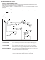
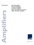
Self-Diagnostic Circuit
$
,&
$
0$,18&20
+$
,&
<&-81*/(
67%</('
675
67%</('
2&3
293
/2:%(55
&/.2
6&/
'$72
6'$
5<
4
$&5/<
$.% &57
9'<
93527 +3527
5
5
44
6(721
5
,&
4
'
9
'
4
'
92&3
293
%2&3
'
'
4
6(79
$
7%
,&
815(*9
'
,
,&
%293
2
67%<9
4
4
'
293
4
+B overcurrent (OCP)
Occurs when an overcurrent (more than 6A) on the +B (135V) line is detected by R6598/
R6591. It will cause Q6520 to turn on and force the AC relay to turn off through Q6532 and
Q6530.
+B overvoltage (OVP)
Occurs when one overvoltage (more than +140V) on the +B (135V) line is detected by
IC6505 or an overvoltage (more than 0.5V) on the unregulator 7V line is detected by D6014.
The AC Relay will turn off through Q6532 and Q6530.
Vertical Deflection Stopped
Occurs when an absence of the vertical deflection pulse is detected by IC1305. Power supply
will shut down when waveform interval exceeds 2 seconds.
White Balance Failure
If the RGB levels do not balance within 2 seconds after the power is turned on, this error will
be detected by IC3005. The unit will stay on, but there will be no picture.
*(Refers to the RGB levels of the AKB detection Ref pulse that detects 1K).
Low B OCP/Error
Occurs when set 5V is out.
H-Stop
—6—
KV-32XBR400/36XBR400/38DRC1/38DRC1C
SAFETY CHECK-OUT
After correcting the original service problem, perform the
following safety checks before releasing the set to the
customer:
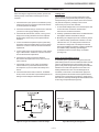
Leakage Test
The AC leakage from any exposed metal part to earth
ground and from all exposed metal parts to any exposed
metal part having a return to chassis, must not exceed 0.5
mA (500 microamperes). Leakage current can be
measured by any one of three methods.
1. Check the area of your repair for unsoldered or poorly
soldered connections. Check the entire board surface
for solder splashes and bridges.
2. Check the interboard wiring to ensure that no wires are
“pinched” or touching high-wattage resistors.
3. Check that all control knobs, shields, covers, ground
straps, and mounting hardware have been replaced.
Be absolutely certain that you have replaced all the
insulators.
1. A commercial leakage tester, such as the Simpson 229
or RCA WT-540A. Follow the manufacturers'
instructions to use these instructions.
2. A battery-operated AC milliammeter. The Data Precision
245 digital multimeter is suitable for this job.
4. Look for unauthorized replacement parts, particularly
transistors, that were installed during a previous repair.
Point them out to the customer and recommend their
replacement.
5. Look for parts which, though functioning, show obvious
signs of deterioration. Point them out to the customer
and recommend their replacement.
6. Check the line cords for cracks and abrasion.
Recommend the replacement of any such line cord
to the customer.
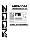
3. Measuring the voltage drop across a resistor by means
of a VOM or battery-operated AC voltmeter. The “limit”
indication is 0.75 V, so analog meters must have an
accurate low voltage scale. The Simpson’s 250 and
Sanwa SH-63TRD are examples of passive VOMs that
are suitable. Nearly all battery-operated digital
multimeters that have a 2 VAC range are suitable
(see Figure A).
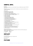
How to Find a Good Earth Ground
7. Check the B+ and HV to see if they are specified
values. Make sure your instruments are accurate;
be suspicious of your HV meter if sets always have
low HV.
8. Check the antenna terminals, metal trim, “metallized”
knobs, screws, and all other exposed metal parts for AC
leakage. Check leakage as described below.
A cold-water pipe is a guaranteed earth ground; the coverplate retaining screw on most AC outlet boxes is also at earth
ground. If the retaining screw is to be used as your earth
ground, verify that it is at ground by measuring the resistance
between it and a cold-water pipe with an ohmmeter. The
reading should be zero ohms. If a cold-water pipe is not
accessible, connect a 60- to 100-watt trouble- light (not a
neon lamp) between the hot side of the receptacle and the
retaining screw. Try both slots, if necessary, to locate the hot
side on the line; the lamp should light at normal brilliance if the
screw is at ground potential (see Figure B).
Trouble Light
AC Outlet Box
Ohmmeter
Cold-water Pipe
Figure A. Using an AC voltmeter to check AC leakage.
Figure B. Checking for earth ground.
—7—
KV-32XBR400/36XBR400/38DRC1/38DRC1C
SECTION 1
GENERAL
The instructions mentioned here are partial abstracts from the Operating Instruction Manual. The page numbers shown reflect
those of the Operating Instruction Manual.
Introducing the FD Trinitron Wega
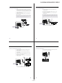
Installing the TV
Using the Remote Control
Cable and Antenna
Inserting Batteries
If your cable provider does not feature local channels, you may find
this set up convenient.
Insert two size AA (R6) batteries (supplied) by matching the + and –
on the batteries to the diagram inside the battery compartment.
AUX
CATV cable
Rear of TV
(No connection to
TO CONVERTER)
TO CONVERTER
Antenna cable
✍ Remove the batteries to avoid damage from possible battery leakage whenever you
VHF/UHF
anticipate that the remote control will not be used for an extended period.
Select CABLE or antenna (ANT) mode by pressing ANT on the remote
control.
Handle the remote control with care. Avoid dropping it, getting it wet, or placing it in
direct sunlight, near a heater, or where the humidity is high.
✍ In order to receive channels with an antenna, you need to turn your Cable to OFF and
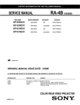
Remote Control
Overview
MUTING
POWER
perform the Auto Program function (see page 30).
Here’s an overview of the buttons on the remote control you will
probably use most often. For a complete description of the remote
control, see “Using the Remote Control” on page 40.
To Do This ...
Use This Button
Turn the TV
on and off
TV (POWER)
Select channels
directly
0 – 9 and ENTER
Scan through
channels
CH +/-
TV
PICTURE
MODE
SLEEP
DISPLAY
ANT
GUIDE
1
2
3
4
5
6
7
8
JUMP
9
FUNCTION
VCR/DVD SAT/CABLE
VOL
FAVORITES
TV
FREEZE
CH
MENU
AV 1 2 3 DVD
RM -Y174
1 Connect the coaxial connector from your cable service to the
cable box’s IN jack.
Press 0 – 9 to select a channel, the channel changes
after 2 seconds. Press ENTER for immediate selection.
2 Using a coaxial cable, connect the cable box’s OUT jack to the
TV’s VHF/UHF jack.
Adjust the volume
VOL +/-
Switch video inputs
(such as a VCR)
TV/VIDEO
Press repeatedly to toggle through all video inputs.
Display the Menu to
make changes to the
TV
MENU
View the Favorite
Channels list
FAVORITES
VHF/UHF
Cable
z To scan rapidly through the channels, press and hold down
the CH+ or CH- button.
ENTER
TV/VIDEO
Some pay cable TV systems use scrambled or encoded signals that
require a cable box to view all channels.
Cable Box
0
RESET
Cable Box
Connections
VCR/DVD SAT/CABLE
Rear of TV
IN
OUT
Cable box
For details, see “Using the Menus” on page 25.
✍ If you will be controlling all channel selection through your cable box, you should
consider using the Channel Fix feature (see page 30).
For details, see “Using Favorite Channels” on
page 20.
Using the on-screen
functions
TV
VOL
FAVORITES
CH
MENU
Move
Select
3
7
Installing the TV
Installing the TV
Connecting a VCR and Cable
Cable Box and Cable
For this set up, you can switch between scrambled channels (through
your cable box), and normal (CATV) channels by pressing ANT on the
remote control.
1 Connect the cable TV cable to the VCR’s IN jack.
2 Using a coaxial cable, connect the VCR’s OUT jack to the TV’s
VHF/UHF jack.
Cable box
AUX
3 Using an A/V cable, connect the VCR’s A/V OUT jacks to the
Rear of TV
IN
TV’s A/V IN jacks.
OUT
✍ If your VCR has an S VIDEO jack: For best picture quality, use an S VIDEO connection
TO CONVERTER
75-ohm coaxial cable (not supplied)
instead of the yellow video cable on your combined A/V cable. Using an S VIDEO cable,
connect the VCR’s S VIDEO OUT jack to the TV’s S VIDEO IN jack. S VIDEO does not
provide audio, so audio cables must still be connected to provide sound.
Signal
VHF/UHF
TV
CATV cable (unscrambled channels)
✍ Your Sony remote control can be programmed to operate your cable box (see
Coaxial cable
“Programming the Remote Control” on page 42).
VCR
When using Favorite Channel or Twin View, you cannot view the AUX input in the
window picture.
z
Cable
AUDIO-R (red)
AUDIO-L (white)
VIDEO (yellow)
Pressing ANT switches between these inputs.
A/V cable
✍ If you are connecting a cable box through the AUX input and would like to switch
between the AUX and normal (CATV) input you should consider using the Channel Fix
feature (see page 30).
9
8
—8—
KV-32XBR400/36XBR400/38DRC1/38DRC1C
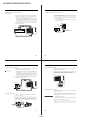
Installing the TV
Installing the TV
Connecting a VCR and Cable Box
Connecting a Satellite Receiver
1 Connect the single (input) jack of the splitter to your incoming
1 Connect the satellite antenna cable to the satellite receiver’s
cable connection, and connect the other two (output) jacks (using
coaxial cable) to IN on your cable box and VHF/UHF on your TV.
SATELLITE IN jack.
2 Using an A/V cable, connect the satellite receiver’s A/V OUT
2 Using a coaxial cable, connect the cable box’s OUT jack to the
jacks to the TV’s A/V IN jacks.
VCR’s VHF/UHF IN jack.
3 Connect a coaxial cable from your cable or antenna to the TV’s
3 Using an A/V cable, connect the VCR’s A/V OUT jacks to the
VHF/UHF jack.
TV’s A/V IN jacks.
✍ If your satellite receiver has an S VIDEO jack: For best picture quality, use an S VIDEO
✍ If your VCR has an S VIDEO jack: For best picture quality, use an S VIDEO connection
connection instead of the yellow video cable on your combined A/V cable. Using an S
VIDEO cable, connect the satellite receiver’s VIDEO OUT jack to the TV’s S VIDEO IN
jack. S VIDEO does not provide audio, so audio cables must still be connected to provide
sound.
instead of the yellow video cable on your combined A/V cable. Using an S VIDEO cable,
connect the VCR’s S VIDEO OUT jack to the TV’s S VIDEO IN jack. S VIDEO does not
provide audio, so audio cables must still be connected to provide sound.
VCR
TV
Coaxial
cable
Coaxial
cable
Cable
box
TV
Satellite receiver
Satellite
antenna
cable
AUDIO-R (red)
AUDIO-L (white)
VIDEO (yellow)
Coaxial
cable
Splitter
(not supplied)
A/V cable
AUDIO-R (red)
AUDIO-L (white)
VIDEO (yellow)
A/V cable
10
12
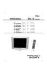
Installing the TV
Installing the TV
Connecting a Satellite Receiver with a VCR
Connecting an Audio Receiver
1 Connect the satellite antenna cable to the satellite receiver’s
1 Using audio cables, connect the TV’s AUDIO OUT jacks to the
SATELLITE IN jack.
audio receiver’s audio LINE IN jacks.
2 Connect the CATV cable to the VCR’s VHF/UHF IN jack.
3 Using a coaxial cable, connect the VCR’s OUT jack to the TV’s
TV
VHF/UHF jack.
4 Using an A/V cable, connect the satellite receiver’s A/V OUT
jacks to the VCR’s A/V IN jacks.
5 Using an A/V cable, connect the VCR’s A/V OUT jacks to the
TV’s A/V IN jacks.
Coaxial
cable
AUDIO-R
(red)
Satellite receiver
TV
Line
input
Coaxial
cable
VCR
AUDIO-R (red)
AUDIO-L (white)
VIDEO (yellow)
A/V cable
13
14
—9—
AUDIO-L
(white)
KV-32XBR400/36XBR400/38DRC1/38DRC1C
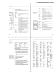
Installing the TV
Installing the TV
Connecting a DVD Player with Component
Video Connectors
Connecting a DVD Player with A/V Connectors
✍ If your DVD player has video component output connectors: for best picture quality use
1 Using three separate component video cables, connect the DVD
the connection described on page 15.
player’s Y, PB, and PR jacks to the Y, PB, and PR jacks on the TV.
✍ The Y, PB, and PR jacks on your DVD player are sometimes labeled Y, CB, and CR, or
1 Using audio cables, connect the DVD player’s audio OUT jacks to
the TV’s audio IN jacks.
Y, B-Y, and R-Y. If so, connect the cables to like colors.
2 Using an S VIDEO cable, connect the DVD player’s S VIDEO jack
The Y, PB, and PR jacks do not provide audio, so audio cables must be connected to
provide sound.
to the TV’s S VIDEO jack.
TV
2 Using an audio cable, connect the DVD player’s audio OUT jacks
to the TV’s audio IN jacks.
S VIDEO
cable
Component video cables
TV
DVD player
DVD player
AUDIO-R (red)
AUDIO-L (white)
Audio cable
AUDIO-R (red)
AUDIO-L (white)
Audio cable
15
16
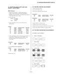
Installing the TV
Installing the TV
Connecting a Digital TV Receiver
Using the CONTROL S Feature
1 Using three separate component video cables, connect the Digital
CONTROL S allows you to control your TV system and other Sony
equipment with one remote control.
TV Set-top box’s Y, PB, and PR jacks to the TV.
z Be sure to read the
manual for the Set-top box.
✍ The Y, PB, and PR jacks do not provide audio, so audio cables must be connected to
To control your other Sony equipment with your TV’s remote control,
use a CONTROL S cable (not supplied) to connect the equipment’s
CONTROL S IN jack to the TV’s CONTROL S OUT jack.
provide sound.
Component input (Y, PB, and PR) is recommended for optimum picture quality. You
may also use component video or S Video connections.
TV
2 Using an audio cable, connect the DTV Set-top box’s audio OUT
jacks to the TV’s audio IN jacks.
Component video cables
TV
DTV Set-top box
1
VIDEO
2
3
Y
S VIDEO
PB
(MONO)
PR
VIDEO
AUDIO/VIDEO OUT
AUDIO-R (red)
AUDIO-L (white)
Setting Up the TV Automatically
Audio cable
After you finish connecting your TV, you need to run Auto Setup to
set up your channels.
Connecting a Camcorder
✍ The Auto Setup feature does not apply for installations that use a cable box for all
channel selection.
1 Using A/V cables, connect the camcorder’s A/V OUT jacks to
the TV’s A/V IN jacks.
Using Auto Setup
✍ If you have a mono camcorder, connect its left audio output to the TV’s AUDIO L jack.
1 Press POWER to turn on the TV.
The first time you turn on the TV, the Auto Setup screen appears.
For easy connection of the camcorder, the TV has front A/V inputs (shown below).
However, if you prefer, you can also connect the camcorder to the TV’s rear A/V IN jacks.
2 Press CH+ to run Auto Setup or press CH– to exit.
✍ You can run Auto Program by selecting it in the Channel menu, as described on
page 30.
MENU
AUDIO-R (red)
AUDIO-L (white)
VIDEO (yellow)
A/V output
17
18
— 10 —