1
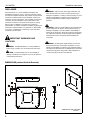
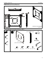
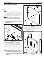
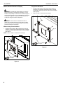
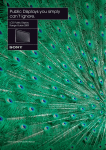
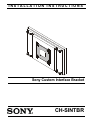
INSTALLATION INSTRUCTIONS
Sony Custom Interface Bracket
CH-SINTBR
CH-SINTBR
Installation Instructions
DISCLAIMER
WARNING: Failure to read, thoroughly understand, and
Sony Electronics, Inc., and its affiliated corporations and
subsidiaries (collectively, "Sony"), intend to make this manual
accurate and complete. However, Sony makes no claim that the
information contained herein covers all details, conditions or
variations, nor does it provide for every possible contingency in
connection with the installation or use of this product. The
information contained in this document is subject to change
without notice or obligation of any kind. Sony makes no
representation of warranty, expressed or implied, regarding the
information contained herein. Sony assumes no responsibility
for accuracy, completeness or sufficiency of the information
contained in this document.
follow all instructions can result in serious personal injury,
damage to equipment, or voiding of factory warranty! It is the
installer’s responsibility to make sure all components are
properly assembled and installed using the instructions
provided.
WARNING: Failure to provide adequate structural strength
for this component can result in serious personal injury or
damage to equipment! It is the installer’s responsibility to
make sure the structure to which this component is attached
can support five times the combined weight of all equipment.
Reinforce the structure as required before installing the
component.
IMPORTANT WARNINGS AND
CAUTIONS!
WARNING: Exceeding the weight capacity can result in
serious personal injury or damage to equipment! It is the
installer’s responsibility to make sure the combined weight of
all components attached to the CH-SINTBR does not exceed
125 lbs (56.70 kg) when using a 200 x 200 hole pattern or
175 lbs (79.38 kg) for all other hole patterns.
WARNING: A WARNING alerts you to the possibility of
serious injury or death if you do not follow the instructions.
CAUTION: A CAUTION alerts you to the possibility of
damage or destruction of equipment if you do not follow the
corresponding instructions.
DIMENSIONS (without Vertical Brackets)
425
16.75
13
.50
20
.80
ADDED
DEPTH
28
1.09
65
2.56
78
3.06
50
1.97
380
14.96
DIMENSIONS: [MILLIMETERS]
INCHES
2
Installation Instructions
CH-SINTBR
DIMENSIONS (with Vertical Brackets)
466
18.33
37
1.46
115
4.53
100
3.94
23
.91
ADDED
DEPTH
22
.87
451
17.75
DIMENSIONS: [MILLIMETERS]
INCHES
TOOLS REQUIRED FOR INSTALLATION / PARTS
B (2)
[Vertical interface bracket]
C (4)
[Threaded
mounting
button]
1/8"
(Included)
D (4)
[Non-threaded
mounting button]
A (1)
[Center interface bracket]
M4
(Included)
J (1)
1/8"
E (8)
10-24 x 1/2"
F (4)
M6 x 25mm
G (4)
M6 x 30mm
H (4)
.750 x .344 x .500
K (1)
M4
3
CH-SINTBR
Installation Instructions
LEGEND
Tighten Fastener
Adjust
Apretar elemento de fijación
Ajustar
Befestigungsteil festziehen
Einstellen
Apertar fixador
Ajustar
Serrare il fissaggio
Regolare
Bevestiging vastdraaien
Afstellen
Serrez les fixations
Ajuster
Loosen Fastener
Hex-Head Wrench
Aflojar elemento de fijación
Llave de cabeza hexagonal
Befestigungsteil lösen
Sechskantschlüssel
Desapertar fixador
Chave de cabeça sextavada
Allentare il fissaggio
Chiave esagonale
Bevestiging losdraaien
Zeskantsleutel
Desserrez les fixations
Clé à tête hexagonale
ASSEMBLY
The CH-SINTBR custom interface bracket kit includes the hardware necessary to install each of the display models listed in Table 1
below. Refer to Table 1 to determine which hardware is required for each display installation.
Model Number
Center
Bracket (A)
FWD-32LX2
1
FWD-40LX2
1
FWD-S42H1
1
FWD-S47H1
1
FWD-50PX3
1
Vertical
Brackets (B)
Threaded
Buttons (C)
4
4
2
4
8
4
4
2
Non-Threaded
Buttons (D)
#10-24 x 1/2"
Screws (E)
*
4
4
4
8
4
4
KLH-W32
1
4
4
KLH-40X1
1
4
4
GXD-L52H1
1
2
M6 x 25mm
Screws (F)
4
4
Spacer
s (H)
4
4
*
4
4
4
4
8
KDL-32M4000
M6 x 30mm
Screws (G)
4
4
4
4
4
4
4
4
KDL-37M4000
1
4
4
4
4
KDL-40SL140
1
4
4
4
4
KDL-46SL140
1
4
*
4
4
4
4
4
4
KDL-32N4000
4
KDL-32NL140
4
4
KDL-37N4000
1
4
KDL-37NL140
1
4
*
4
4
4
KDL-32EX500
4
4
KDL-40EX500
1
4
4
4
4
KDL-46EX500
1
4
4
4
4
KDL-55EX500
1
4
4
4
4
KDL-60EX500
1
4
4
4
4
KDL-32S5100
4
4
KDL-40S5100
1
4
4
4
4
KDL-46S5100
1
4
4
4
4
KDL-52S5100
1
4
4
4
4
Table 1
* Use the longest screw that fully threads into the display.
4
Installation Instructions
CH-SINTBR
ATTACH MOUNTING BUTTONS
Attach Mounting Buttons Directly to Display
For displays with a 200 x 200 hole pattern, no interface bracket
is necessary for installation. For all other hole patterns, skip
ahead to Attach Mounting Buttons to Interface Bracket
section.
1
(E) x 4
(A)
WARNING: Exceeding the weight capacity can result in
serious personal injury or damage to equipment! It is the
installer’s responsibility to make sure the combined weight of
all components attached to the CH-SINTBR does not exceed
125 lbs (56.70 kg) when using a 200 x 200 hole pattern.
WARNING: When screws are threaded into back of
display, they should thread into the holes easily. DO NOT
force a stuck screw into the display. Doing so could cause
permanent damage to the display!
1.
Install four M6 x 25mm button head cap screws (F) through
non-threaded mounting buttons (D) and into holes on back
of display. (See Figure 1)
(C) x 4
Figure 2
1.
(D) x 4
Install four #10-24 x 1/2" button head cap screws (E)
through corresponding holes in interface bracket (A) and
vertical brackets (B). (See Figure 3)
Display
Alternate mounting button positions
(B) x 2
1
(F) x 4
Figure 1
Attach Mounting Buttons to Interface Bracket
1.
(A)
Insert four #10-24 x 1/2" button head cap screws (E)
through four inner holes of interface plate and into four
threaded mounting buttons (C). (See Figure 2)
NOTE: For wide mounting configurations on mounting device,
mounting buttons may be installed to wider holes on
interface bracket. (See Figure 3)
Attach Vertical Brackets to Interface Bracket
NOTE: For wide hole configurations on display, using the
vertical interface brackets may be required. If this is the
case, these brackets must be attached to the center
interface bracket prior to attaching bracket to display.
Otherwise, skip ahead to Attach Interface Bracket to
Display section.
1
(E) x 4
Figure 3
5
CH-SINTBR
Installation Instructions
Attach Interface Bracket to Display
Using Vertical Brackets
1.
Install four M6 x 25mm or M6 x 30mm button head cap
screws (F or G) through corresponding holes on vertical
brackets (B), spacers (H) and into holes on back of display.
(See Figure 5)
2.
Refer to Table 1 to determine screw length.
WARNING: Exceeding the weight capacity can result in
serious personal injury or damage to equipment! It is the
installer’s responsibility to make sure the combined weight of
all components attached to the CH-SINTBR does not exceed
125 lbs (56.70 kg) when using a 200 x 200 hole pattern or
175 lbs (79.38 kg) for all other hole patterns.
(H) x 4
WARNING: When screws are threaded into back of
display, they should thread into the holes easily. DO NOT
force a stuck screw into the display. Doing so could cause
permanent damage to the display!
Without Using Vertical Brackets
1.
Install four M6 x 25mm or M6 x 30mm button head cap
screws (F or G) through corresponding holes on interface
bracket (A), spacers (H) and into holes on back of display.
(See Figure )
(B) x 2
NOTE: Refer to Table 1 to determine screw length.
(H) x 4
(A)
1
(F or G) x 4
Figure 5
1
(F or G) x 4
Figure 4
6
Installation Instructions
CH-SINTBR
7
CH-SINTBR
8832-002047 Rev00
10/10
Installation Instructions
Sony Electronics Inc.
1 Sony Drive
Park Ridge, NJ 07656
201-930-1000
www.sony.com/displaysystems