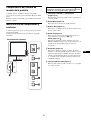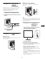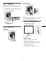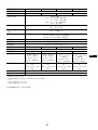
1
2-630-290-22(1) TFT LCD Color Computer Display SDM-S75 SDM-S95 © 2005 Sony Corporation Owner’s Record NOTICE This notice is applicable for USA/Canada only. If shipped to USA/Canada, install only a UL LISTED/CSA LABELLED power supply cord meeting the following specifications: SPECIFICATIONS Plug Type Nema-Plug 5-15p Cord Type SVT or SJT, minimum 3 × 18 AWG Length Maximum 15 feet Rating Minimum 7 A, 125 V The model and serial numbers are located at the rear of the unit. Record these numbers in the spaces provided below. Refer to them whenever you call upon your dealer regarding this product. Model No. Serial No. WARNING To reduce the risk of fire or electric shock, do not expose this apparatus to rain or moisture. NOTICE Cette notice s’applique aux Etats-Unis et au Canada uniquement. Si cet appareil est export* aux Etats-Unis ou au Canada, utiliser le cordon d’alimentation portant la mention UL LISTED/CSA LABELLED et remplissant les conditions suivantes: SPECIFICATIONS Type de fiche Fiche Nema 5-15 broches Cordon Type SVT ou SJT, minimum 3 × 18 AWG Longueur Maximum 15 pieds Tension Minimum 7 A, 125 V Dangerously high voltages are present inside the unit. Do not open the cabinet. Refer servicing to qualified personnel only. FCC Notice This equipment has been tested and found to comply with the limits for a Class B digital device, pursuant to Part 15 of the FCC Rules. These limits are designed to provide reasonable protection against harmful interference in a residential installation. This equipment generates, uses, and can radiate radio frequency energy and, if not installed and used in accordance with the instructions, may cause harmful interference to radio communications. However, there is no guarantee that interference will not occur in a particular installation. If this equipment does cause harmful interference to radio or television reception, which can be determined by turning the equipment off and on, the user is encouraged to try to correct the interference by one or more of the following measures: – Reorient or relocate the receiving antenna. – Increase the separation between the equipment and receiver. – Connect the equipment into an outlet on a circuit different from that to which the receiver is connected. – Consult the dealer or an experienced radio/TV technician for help. You are cautioned that any changes or modifications not expressly approved in this manual could void your authority to operate this equipment. As an ENERGY STAR Partner, Sony Corporation has determined that this product meets the ENERGY STAR guidelines for energy efficiency. IMPORTANTE This monitor complies with the TCO’99 guidelines. Para prevenir cualquier mal funcionamiento y evitar daños, por favor, lea detalladamente este manual de instrucciones antes de conectar y operar este equipo. (for the black model) If you have any questions about this product, you may call; Sony Customer Information Services Center 1-800-222-7669 or http://www.sony.com/ This monitor complies with the TCO’03 guidelines. Declaration of Conformity Trade Name Model Note : SONY : SDM-S75 /S95 : means any number or alphanumeric character. Responsible Party : Sony Electronics Inc. Address : 16530 Via Esprillo, San Diego, CA 92127 U.S.A. Telephone Number : 858-942-2230 (for the silver model) This device complies with part 15 of the FCC rules. Operation is subject to the following two conditions: (1) This device may not cause harmful interference, and (2) this device must accept any interference received, including interference that may cause undesired operation. Be sure to confirm the carton that came with your display. The ID label of your display model is located at the rear of the display. 2 Table of Contents Precautions. . . . . . . . . . . . . . . . . . . . . . . . . . . . . . . . . . . . . . . . . . . . 4 Checking the model name of the display . . . . . . . . . . . . . . . . . . . . . 5 Identifying parts and controls . . . . . . . . . . . . . . . . . . . . . . . . . . . . . . 5 Setup . . . . . . . . . . . . . . . . . . . . . . . . . . . . . . . . . . . . . . . . . .6 Setup 1: Assemble the stand . . . . . . . . . . . . . . . . . . . . . . . . . . . . . . 6 Setup 2: Connect the video signal cables . . . . . . . . . . . . . . . . . . . . 7 Setup 3: Connect the audio cords . . . . . . . . . . . . . . . . . . . . . . . . . . 8 Setup 4: Connect the power cord . . . . . . . . . . . . . . . . . . . . . . . . . . 9 Setup 5: Secure the cords . . . . . . . . . . . . . . . . . . . . . . . . . . . . . . . . 9 Setup 6: Turn on the display and computer . . . . . . . . . . . . . . . . . . . 9 Setup 7: Adjust the tilt and height . . . . . . . . . . . . . . . . . . . . . . . . . 10 Selecting the input signal (INPUT1/INPUT2) . . . . . . . . . . . . . . . . . 11 Customizing Your Display . . . . . . . . . . . . . . . . . . . . . . .12 • Macintosh is a trademark licensed to Apple Computer, Inc., registered in the U.S.A. and other countries. • Windows® is registered trademarks of Microsoft Corporation in the United States and other countries. • IBM PC/AT and VGA are registered trademarks of IBM Corporation of the U.S.A. • VESA and DDC™ are trademarks of the Video Electronics Standards Association. • ENERGY STAR is a U.S. registered mark. • Adobe and Acrobat are trademarks of Adobe Systems Incorporated. • All other product names mentioned herein may be the trademarks or registered trademarks of their respective companies. • Furthermore, “™” and “®” are not mentioned in each case in this manual. Navigating the menu. . . . . . . . . . . . . . . . . . . . . . . . . . . . . . . . . . . . 12 Menu options list. . . . . . . . . . . . . . . . . . . . . . . . . . . . . . . . . . . . . . . 13 PICTURE ADJUST menu . . . . . . . . . . . . . . . . . . . . . . . . . . . . . 14 COLOR menu . . . . . . . . . . . . . . . . . . . . . . . . . . . . . . . . . . . . . . . 14 SHARPNESS menu. . . . . . . . . . . . . . . . . . . . . . . . . . . . . . . . . . 14 0 MODE RESET menu (PICTURE ADJUST menu only). . . . . . . 14 SCREEN menu (analog RGB signal only) . . . . . . . . . . . . . . . . 14 MENU POSITION menu . . . . . . . . . . . . . . . . . . . . . . . . . . . . . . 15 INPUT SENSING menu . . . . . . . . . . . . . . . . . . . . . . . . . . . . . . . 15 LANGUAGE menu . . . . . . . . . . . . . . . . . . . . . . . . . . . . . . . . . . . 15 0 RESET menu (reset to the default setting) . . . . . . . . . . . . . . . . 15 MENU LOCK menu . . . . . . . . . . . . . . . . . . . . . . . . . . . . . . . . . 15 Technical Features . . . . . . . . . . . . . . . . . . . . . . . . . . . . .16 Power saving function. . . . . . . . . . . . . . . . . . . . . . . . . . . . . . . . . . . 16 Reducing the power consumption (ECO mode) . . . . . . . . . . . . . . . 16 Automatic picture quality adjustment function (analog RGB signal only) . . . . . . . . . . . . . . . . . . . . . . . . . . . . . . . . 16 Troubleshooting. . . . . . . . . . . . . . . . . . . . . . . . . . . . . . . .17 On-screen messages . . . . . . . . . . . . . . . . . . . . . . . . . . . . . . . . . . . 17 Trouble symptoms and remedies . . . . . . . . . . . . . . . . . . . . . . . . . . 18 Specifications. . . . . . . . . . . . . . . . . . . . . . . . . . . . . . . . . .20 TCO’99 Eco-document (for the black model) . . . . . . . . . . . . . . . . . . .i TCO’03 Eco-document (for the silver model) . . . . . . . . . . . . . . . . . . ii http://www.sony.net/ 3 US Note on the LCD (Liquid Crystal Display) Precautions Please note that the LCD screen is made with highprecision technology. However, black points or bright points of light (red, blue, or green) may appear constantly on the LCD screen, and irregular colored stripes or brightness may appear on the LCD screen. This is not malfunction. (Effective dots: more than 99.99%) Warning on power connections • Use the supplied power cord. If you use a different power cord, be sure that it is compatible with your local power supply. For the customers in the U.S.A. If you do not use the appropriate cord, this display will not conform to mandatory FCC standards. For the customers in the UK If you use the display in the UK, be sure to use the appropriate UK power cord. Maintenance • Be sure to unplug the power cord from the power outlet before cleaning your display. • Clean the LCD screen with a soft cloth. If you use a glass cleaning liquid, do not use any type of cleaner containing an anti-static solution or similar additive as this may scratch the LCD screen’s coating. • Clean the cabinet, panel, and controls with a soft cloth lightly moistened with a mild detergent solution. Do not use any type of abrasive pad, scouring powder, or solvent, such as alcohol or benzine. • Do not rub, touch, or tap the surface of the screen with sharp or abrasive items such as a ballpoint pen or screwdriver. This type of contact may result in a scratched picture tube. • Note that material deterioration or LCD screen coating degradation may occur if the display is exposed to volatile solvents such as insecticide, or if prolonged contact is maintained with rubber or vinyl materials. Example of plug types for 100 to 120 V AC for 200 to 240 V AC for 240 V AC only The equipment should be installed near an easily accessible outlet. Installation Do not install or leave the display: • In places subject to extreme temperatures, for example near a radiator, heating vent, or in direct sunlight. Subjecting the display to extreme temperatures, such as in an automobile parked in direct sunlight or near a heating vent, could cause deformations of the casing or malfunctions. • In places subject to mechanical vibration or shock. • Near any equipment that generates a strong magnetic field, such as a TV or various other household appliances. • In places subject to inordinate amounts of dust, dirt, or sand, for example near an open window or an outdoor exit. If setting up temporarily in an outdoor environment, be sure to take adequate precautions against airborne dust and dirt. Otherwise irreparable malfunctions could occur. Transportation • Disconnect all the cables from the display. If you use a height adjustable stand adjust its height to the highest position and hold both sides of the LCD display securely. Be careful not to scratch the screen when transporting. If you drop the display, you may injured or the display may be damaged. • When you transport this display for repair or shipment, use the original carton and packing materials. • Replace the stopper pin for the height adjustable stand to fix the stand during the transportation. Handling the LCD screen Disposal of the display • Do not leave the LCD screen facing the sun as it can damage the LCD screen. Take care when you place the display by a window. • Do not push on or scratch the LCD screen. Do not place a heavy object on the LCD screen. This may cause the screen to lose uniformity or cause LCD panel malfunctions. • If the display is used in a cold place, a residual image may appear on the screen. This is not a malfunction. The screen returns to normal as the temperature rises to a normal operating level. • If a still picture is displayed for a long time, a residual image may appear for a while. The residual image will eventually disappear. • The LCD panel becomes warm during operation. This is not a malfunction. • Do not dispose of this display with general household waste. • The fluorescent tube used in this display contains mercury. Disposal of this display must be carried out in accordance to the regulations of your local sanitation authority. For customers in the United States This product contains mercury. Disposal of this product may be regulated if sold in the United States. For disposal or recycling information, please contact your local authorities or the Electronics Industries Alliance (http://www.eiae.org). 4 Checking the model name of the display The contents with mark for specifications vary depending on the models. For details, see “Specifications” (page 20). Check the model name of the display first. The model name is located at the rear of the display (Example : SDM-S75A). 1 1 (Power) switch and 1 (power) indicator (pages 9, 16) This switch turns the display on. To turn the display off, press this switch again. You cannot use some of the functions or menu options for certain display models. 2 MENU button (pages 12) This button turns the menu screen on and off. Identifying parts and controls 3 m/M buttons (page 12) These buttons are used to select the menu items and make adjustments. See the pages in parentheses for further details. The illustration only shows one of all the models that are available for this display. 4 OK button (page 12) This button activates the selected menu item and adjustments made using the m/M buttons (3). INPUT (page 11) These buttons switch the video input signal between INPUT1 and INPUT2 when two computers are connected to the display. (Only available when menu is turned off.) Front of the display 5 ECO button (page 16) This button is used to reduce the power consumption. When the menu screen is not displayed, you can also automatically adjust the picture quality for the current input signal while keeping pressing this button for more than 3 seconds (One touch Auto adjust). (analog RGB signal only) MENU 6 Audio output jack (page 8) This jack outputs audio signals to speakers or other audio equipment. INPUT OK ECO 5 US Real of the display Setup Before using your display, check that the following items are included in your carton: • LCD display • Power cord • Stand Base • HD15-HD15 video signal cable (analog RGB) • DVI-D video signal cable (digital RGB) • CD-ROM (utility software for Windows/Macintosh, Operating Instructions, etc.) • Warranty card • Quick Setup Guide qa 0 The contents with mark for specifications vary depending on the models. For details, “Specifications” (page 20). Setup 1: Assemble the stand 7 8 qs 9qd Do not press the LCD display when placing or raising the display straight on a desk or a like. It may affect the uniformity of the screen or damage the LCD display. 7 AC IN connector (page 9) This connector connects the power cord (supplied). 8 DVI-D input connector (digital RGB) (page 8) This connector inputs digital RGB video signals that comply with DVI Rev.1.0. x When using supplied stand 1 Open the carton and take out the stand base. 9 HD15 input connector (analog RGB) (page 8) This connector inputs analog RGB video signals (0.700 Vp-p, positive) and sync signals. 2 Confirm the supplied items. • Stand Base (with the screw at the bottom side) 3 Place a soft mat or a kind on a flat surface like a 0 Cable holder (page 9) This part secures cables and cords to the display. desk. You may damage the LCD screen and the display itself if putting the display directly on the desk. qa Security lock hole The security lock hole should be used with the Kensington Micro Saver Security System. Micro Saver Security System is a trademark of Kensington. 4 Take the display out from the carton and then place the frame of the laid display along the edge of the desk. The figure shows the height adjustable stand. If you use the fixed stand, your last step of assembling procedure is Step 5. qs Audio jack for INPUT1 This jack inputs audio signals when connected to the audio output jack of a computer or other audio equipment connected to INPUT1. Display qd Audio jack for INPUT2 This jack inputs audio signals when connected to the audio output jack of a computer or other audio equipment connected to INPUT2. Soft mat or a like 6 Stand 5 Hook the stand base holes onto the prongs of stand x When using VESA Stand to attach. 1 Lift the handle of screw to screw the stand base securely. 2 Be sure that the screw is secured and turn the screw handle back. Screws compatible with VESA stand (4) 1 Stand Base You can attach a VESA stand in other brands by removing the supplied stand attached to the display. 2 Screw Setup 2: Connect the video signal cables • Turn off the display and computer before connecting. Notes • Do not touch the pins of the video signal cable connector as this might bend the pins. • Check the alignment of the connector to avoid bending the pins of the video signal cable connector. 6 If you use the height adjustable stand, remove the stopper pin after raising the height adjustable stand straight. 1 Tilt the display up. When using the height adjustable stand, raise the display higher. Stopper Pin Note Do not remove the stopper pin while the stand is laid. It may fall or injure you by the stand neck coming off the stand base impetuously. 7 US 2 Connect the video signal cables to the display. Setup 3: Connect the audio cords If you use the fixed stand, draw the video signal cables through the stand hole first and then connect them to the display. For more details see “Setup 5: Secure the cords.” If you are not intended to output audio, you do not need this connection. x Connect a computer equipped with an HD15 output connector (analog RGB) If you use the fixed stand, draw the audio cords through the stand hole first and then connect them to the display. For more details see “Setup 5: Secure the cords.” Using the supplied HD15-HD15 video signal cable (analog RGB), connect the computer to the display’s HD 15 input connector (analog RGB). 1 Connect the display’s audio input jack and audio output jack of the computer or other audio equipment using the audio cord (not supplied). to the computer’s HD15 output connector (analog RGB) to the HD 15 input connector (analog RGB) to the audio input HD15-HD15 video signal cable (analog RGB) (supplied) to audio output of the computer or other audio equipment audio cord (not supplied) x Connect a computer equipped with a DVI output connector (digital RGB) Using the supplied DVI-D video signal cable (digital RGB), connect the computer to the display’s DVI-D input connector (digital RGB). 2 Connect the audio cable (not supplied) securely to the display’s audio output jack. to the audio output to the computer’s DVI output connector (digital RGB) to the DVI-D input connector (digital RGB) audio cable (not supplied) DVI-D video signal cable (digital RGB) (supplied) Audio output will be changed when the display’s audio input and audio output connection has been completed. Connect audio equipment that is within the input range shown in the display’s audio input specifications. Too high of an input may cause damage to the display. 8 x Height adjustable stand Setup 4: Connect the power cord Draw the cords and cables through the cable holder as illustrated. If you use the fixed stand, draw the power cord through the stand hole first and then connect them to the display. For more details see “Setup 5: Secure the cords.” 1 Connect the supplied power cord securely to the display’s AC IN connector. 2 Connect the other end securely to a power outlet. Note When bounding the cords and cables, be sure to loosen them a little. If they get pulled hard they may come off from the connectors or plugs as you adjust the screen angle. If you stretch the cords and cables too hard they may get damaged. 1 to AC IN to a power outlet Setup 6: Turn on the display and computer 2 1 Press the 1 (power) switch located on the front power cord (supplied) right of the display. The 1 (power) indicator lights up in green. lights in green Setup 5: Secure the cords x Fixed Stand Be sure that the cords and cables have been drawn into the stand hole as illustrated. 2 Turn on the computer. If no picture appears on your screen • Check that the power cord and the video signal cables are properly connected. • If “NO INPUT SIGNAL” appears on the screen: – The computer is in the power saving mode. Try pressing any key on the keyboard or moving the mouse. – Check that the input signal setting is correct by pressing the OK button (page 11). • If “CABLE DISCONNECTED” appears on the screen: – Check that the video signal cables are properly connected. – Check that the input signal setting is correct by pressing the OK button (page 11). 9 US • If “OUT OF RANGE” appears on the screen: Reconnect the old display. Then adjust the computer’s graphics board within the following ranges. Analog RGB Digital RGB Horizontal frequency 28–80 kHz 28–64 kHz Vertical frequency 48–75 Hz 60 Hz Resolution 1280 × 1024 or less For more information about the on-screen messages, see “Trouble symptoms and remedies” on page 18. approx. 175° No need for specific drivers The display complies with the “DDC” Plug & Play standard and automatically detects all the display’s information. No specific driver needs to be installed to the computer. The first time you turn on your computer after connecting the display, the setup Wizard may appear on the screen. If this is the case, follow the onscreen instructions. The Plug & Play display is automatically selected so that you can use this display. approx. 175° When you use the height adjustable stand, the height adjust is also available as below. Hold both sides of the LCD panel, then adjust screen height. The vertical frequency turns to 60 Hz. Since flickers are unobtrusive on the display, you can use it as is. You do not need to set the vertical frequency to any particular high value. approx. 110 mm (4 11/32 inches) Setup 7: Adjust the tilt and height This display can be adjusted within the angles shown below. Hold both sides of the LCD panel, then adjust screen angles. approx. 5° approx. 20° To use the display comfortably Adjust the viewing angle of your display according to the height of your desk and chair, so that light is not reflected from the screen to your eyes. Notes • When adjusting the screen’s angle, be sure not to crash it against any objects around the display. • Do not put any objects under the display when you adjust the height of stand. It may get damaged by accident. 10 Selecting the input signal (INPUT1/ INPUT2) Press the OK button. The input signal change each time you press this button. INPUT OK On-screen message (Appears about 5 seconds on the upper left corner.) Input signal configuration INPUT1 : DVI-D DVI-D input connector (digital RGB) for INPUT1 INPUT2 : HD15 HD15 input connector (analog RGB) for INPUT2 US 11 x Resetting the adjustments to the default settings Customizing Your Display You can reset the adjustments using the RESET menu. For more information about resetting the adjustments, see 0 (RESET) on page 15. Before making adjustments Connect the display and the computer, and turn them on. For the best results, wait for at least 30 minutes before making any adjustments after display is connected to the computer and turned on. You can make numerous adjustments to your display using the on-screen menu. Navigating the menu 1 Display the main menu. Press the MENU button to display the main menu on your screen. MENU 2 Select the menu you want to adjust. Press the m/M buttons to display the desired menu. Press the OK button to select the menu item. INPUT , OK 3 Adjust the item. Press the m/M buttons to make the adjustment, then press the OK button. When you press the OK button, the setting is stored, then the display returns to the previous menu. INPUT , OK 4 Close the menu. Press the MENU button once to return to normal viewing. If no buttons are pressed, the menu closes automatically after about 45 seconds. MENU 12 Menu options list Menu options vary depending on the models. Check your model name on the bottom of the display and refer to the tables below. SDM-S75A/S95AR SDM-S75E/S95ER BACKLIGHT 6 CONTRAST 8 BRIGHTNESS SDM-S75D/S95DR SDM-S75F/S95FR SDM-S75N/S95NR ; PICTURE ADJUST menu ;1) MODE (ECO mode) 1) ; HIGH GAMMA ;1) MIDDLE COLOR 9300K LOW USER 6500K BACKLIGHT sRGB1) SHARPNESS 0 MODE RESET SCREEN ; USER (gain of R and B) 6 CONTRAST ;1) ; 8 BRIGHTNESS ;1) – GAMMA ;1) AUTO COLOR 9300K 6500K PHASE sRGB1) PITCH USER (gain of R and B) H CENTER SHARPNESS V CENTER ; MENU POSITION ; 0 MODE RESET ; INPUT SENSING – SCREEN AUTO LANGUAGE ENGLISH PHASE FRANÇAIS PITCH DEUTSCH H CENTER ESPAÑOL V CENTER ITALIANO MENU POSITION ; NEDERLANDS INPUT SENSING AUTO ON INPUT1 SVENSKA INPUT2 AUTO OFF LANGUAGE 0 RESET MENU LOCK ENGLISH OK FRANÇAIS CANCEL DEUTSCH ON ESPAÑOL OFF ITALIANO NEDERLANDS SVENSKA 0 RESET OK CANCEL MENU LOCK ON OFF 1) 13 CONTRAST, BRIGHTNESS, and GAMMA are not adjustable when “sRGB” selected. US 0 MODE RESET menu (PICTURE ADJUST menu only) PICTURE ADJUST menu For those display with analog inputs, BACKLIGHT, CONTRAST, and BRIGHTNESS can be adjustable when the ECO mode is selected for the USER only. Items Press the M button Press the m button MODE HIGH MIDDLE LOW USER Set the ECO mode. Select the brightness of your display from "HIGH," "MIDDLE," "LOW," or "USER" to save power consumption. You can adjust the subtle tones of your display brightness when selecting the "USER" mode. You can set a variety of mode by setting an input. Sharpens the picture Blurs the picture contrasts. contrasts. Note If you select “sRGB,” you cannot adjust CONTRAST, BRIGHTNESS, and GAMMA. 9300K Bluish hue 6500K Reddish hue sRGB1) When you select “sRGB” the color are adjusted to the sRGB profile. (The sRGB color setting is an industry-standard color space protocol designed for computer products.) When you select “sRGB,” the color settings of your computer must be set to the sRGB profile. USER2) 1) 2) To cancel resetting and return to the menu. Note While the automatic picture quality adjustment function is activated, only the 1 (power) switch is operable. The picture may flicker during this time, but this is not a malfunction. Simply wait a few moments until the adjustment completes. COLOR menu Features CANCEL When the display receives an input signal, it automatically adjusts the picture’s position and sharpness (phase/pitch), and ensures that a clear picture appears on the screen (page 17). Features You can adjust your pictures on the screen to the original coloring. Items You can reset the adjustments of BACKLIGHT, CONTRAST, BRIGHTNESS, GAMMA, COLOR, and SHARPNESS to the default setting. x Automatic picture quality adjustment function 8 BRIGHTNESS Brightens the picture Darkens the picture (Black label). (Black label). GAMMA Features OK SCREEN menu (analog RGB signal only) BACKLIGHT Brightens the screen. Darkens the screen. 6 CONTRAST Items If the automatic picture quality adjustment function of this display did not seem to adjust the picture completely You can make further automatic adjustment of the picture quality for the current input signal. (See AUTO below.) If you still need to make further adjustments to the picture quality You can manually adjust the picture’s sharpness (phase/pitch) and position (horizontal/vertical position). These adjustments are stored in memory and automatically recalled when the display receives the same input signal. These settings may have to be repeated if you change the input signal after reconnecting your computer. You can adjust color temperature finely and that color setting is stored in memory. If a computer or other equipment connected to the display is not sRGBcompliant, color cannot be adjusted to the sRGB profile. When you select “sRGB,” you cannot adjust CONTRAST, BRIGHTNESS, and GAMMA. sRGB is unavailable when HIGH or MIDDLE or LOW mode for ECO mode is selected. (“sRGB” would be gray-out) This adjustment changes the color temperature by increasing or decreasing the R and B components with respect to G (green). G component is fixed. Items Features AUTO Make the appropriate adjustments of the screen’s phase, pitch and horizontal/ vertical position for the current input signal and store them. x Adjust the picture’s sharpness and position manually (PHASE/PITCH/H CENTER/V CENTER) You can adjust the picture’s sharpness and position as follows. SHARPNESS menu 1 Set the resolution to 1280 × 1024, on the computer. Items Press the m/M buttons 2 Load the CD-ROM. SHARPNESS Adjust to sharpen the edge of images, etc. 3 Start the CD-ROM, and display the test pattern. 14 For Windows User When Auto run operates: 1 Click “DISPLAY ADJUSTMENT TOOL (UTILITY)”. 2 Click “Adjust” and confirm the resolution and then click “Next”. 3 Test pattern for PITCH, PHASE, H CENTER and V CENTER appears in order. When Auto run fails to operate: 1 Open “My Computer” and right click the CD-ROM icon. Go to “Explorer” and open the CD-ROM icon. 2 Open [Utility] and then select [Windows]. 3 Start [Win_Utility.exe]. Test pattern appears. Press the m/M buttons PHASE Minimize the horizontal stripes on the screen. PITCH Vertical stripes become vanished. H CENTER Adjust the picture position when your picture does not appear on the center of the screen. V CENTER Features AUTO OFF The input is not changed automatically. Press the OK button to change the input. LANGUAGE menu Items ENGLISH FRANÇAIS DEUTSCH ESPAÑOL ITALIANO NEDERLANDS SVENSKA For Macintosh user 1 Open [Utility] and then select [Mac]. 2 Start [Mac_Utility.exe] Test pattern appears. Items Items Press the m/M buttons MENU POSITION You can change the menu displayed position on the screen. You can choose one of 9 positions. French German Spanish Italian Dutch Swedish Russian Japanese Chinese 0 RESET menu (reset to the default setting) Items Features OK To reset all the adjustment data to the default setting except for the (LANGUAGE) setting. CANCEL To cancel resetting and return to the menu screen. MENU POSITION menu Items Press the m/M buttons MENU LOCK menu INPUT SENSING menu Items Features ON Only the 1 (power) switch will operate. If you attempt any other operation, the (MENU LOCK) icon appears on the screen. OFF Set (MENU LOCK) to off. If (MENU LOCK) has been set to ON, when you press the MENU button, (MENU LOCK) is automatically selected. Those models of digital input search any input signals. You can switch the signals back and forth automatically. Items Features AUTO ON When the selected input has no signal, or when you select an input with the OK button and if it has no input signal, an on-screen message appears. Then the display checks the input signal and switch to other input automatically. When an input is changed, the selected input is displayed on the upper left corner of the screen. When there still is no input signal, the display goes into the power saving mode. INPUT 1 When turning on the display, INPUT1 or INPUT2 will be displayed as priority setting (INPUT SENSING will not function). INPUT 2 15 US Note For those displays with analog inputs, only while the ECO mode is set to USER, are the BACKLIGHT, CONTRAST, and BRIGHTNESS items of the menu available (page 14). Technical Features Power saving function Automatic picture quality adjustment function (analog RGB signal only) This display meets the power-saving guidelines set by VESA, ENERGY STAR, and NUTEK. If the display is connected to a computer or video graphics board that is DPMS (Display Power Management Standard) for Analog input / DMPM (DVI Digital Monitor Power Management) for Digital input compliant, the display will automatically reduce power consumption as shown below. When the display receives an input signal, it automatically adjusts the picture’s position and sharpness (phase/pitch), and ensures that a clear picture appears on the screen. Power mode 1 (power) indicator normal operation green The factory preset mode orange When the display receives an input signal, it automatically matches the signal to one of the factory preset modes stored in the display’s memory to provide a high quality picture at the center of the screen. If the input signal matches the factory preset mode, the picture appears on the screen automatically with the appropriate default adjustments. active off 1) (deep sleep) power off 1) off When your computer enters the “active off” mode, the input signal is cut and NO INPUT SIGNAL appears on the screen. After 5 seconds, the display enters the power saving mode. “deep sleep” is the power saving mode defined by the Environmental Protection Agency. If input signals do not match one of the factory preset modes When the display receives an input signal that does not match one of the factory preset modes, the automatic picture quality adjustment function of this display is activated to ensure that a clear picture always appears on the screen (within the following display frequency ranges): Horizontal frequency: 28–80 kHz Vertical frequency: 48–75 Hz Consequently, the first time the display receives input signals that do not match one of the factory preset modes, the display may take a longer time than normal to display the picture on the screen. This adjustment data is automatically stored in memory so that next time, the display will function in the same way as when the display receives the signals that match one of the factory preset modes. Reducing the power consumption (ECO mode) If you press the ECO button on the front of the display repeatedly, you can select the screen brightness. ECO : HIGH ECO : MIDDLE ECO , If you adjust the phase, pitch, and picture position manually E C O : L OW For some input signals, the automatic picture quality adjustment function of this display may not completely adjust the picture position, phase, and pitch. In this case, you can set these adjustments manually (page 14). If you set these adjustments manually, they are stored in memory as user modes and automatically recalled whenever the display receives the same input signals. ECO : USER 50 Each mode appears on the screen and the screen brightness is reduced according to the mode. The menu automatically disappears after about 5 seconds. Screen brightness and power consumption are reduced as the mode changes from HIGH to MIDDLE to LOW. Note While the automatic picture quality adjustment function is activated, only the 1 (power) switch will operate. The picture may flicker during this time, but this is not a malfunction. Simply wait a few moments until the adjustment completes. The default setting of the screen brightness is set to HIGH. If you select USER, you can adjust the backlight level by pressing the m/M buttons, the same as when you select BACKLIGHT using the menu. 16 If “NO INPUT SIGNAL” appears on the screen Troubleshooting This indicates that no signal is being input via the currently selected connector. When INPUT SENSING (page 15) is set to ON, the display finds another input signal and changes the input automatically. Before contacting technical support, refer to this section. Example On-screen messages I NFORMA T I ON If there is something wrong with the input signal, one of the following messages appears on the screen. To solve the problem, see “Trouble symptoms and remedies” on page 18. NO I NPUT S I GNA L I NPUT 1 : DV I - D GO TO POWER SAVE If “OUT OF RANGE” appears on the screen This indicates that the input signal is not supported by the display’s specifications. Check the following items. For more information about on-screen messages, see “Trouble symptoms and remedies” on page 18. When input signals cannot be found “GO TO POWER SAVE” message appears. 5 seconds later, the power saving mode starts. If “xxx.x kHz/xxx Hz” is displayed This indicates that either the horizontal or vertical frequency is not supported by the display’s specifications. The figures indicate the horizontal and vertical frequencies of the current input signal. If “CABLE DISCONNECTED” appears on the screen This indicates that the video signal cable has been disconnected from the currently selected connector. When INPUT SENSING (page 15) is set to ON, the display finds another input signal and changes the input automatically. Example I NFORMA T I ON Example OUT OF RANGE I NPUT 1 : DV I - D x x x . x kHz / x x xHz I NFORMA T I ON CAB L E D I SCONNECT ED I NPUT 1 : DV I - D GO TO POWER SAVE If “RESOLUTION > 1280 × 1024” is displayed This indicates that the resolution is not supported by the display’s specifications (1280 × 1024 or less). When input signals cannot be found “GO TO POWER SAVE” message appears. 45 seconds later, the power saving mode starts. Example I NFORMA T I ON OUT OF RANGE I NPUT 1 : DV I - D RESOL UT I ON > 1 2 8 0 X 1 0 2 4 17 US Trouble symptoms and remedies If a problem occurs as a result of a connected computer or other equipment, refer to the connected computer/equipment’s instruction manual. Symptom Check these items No picture If the 1 (power) indicator is not lit, or, 1 (power) indicator turns on in orange, • Check that the 1 (power) switch is on. If the 1 (power) indicator will not light up when the 1 (power) switch is pressed, • Check that the power cord is properly connected. If CABLE DISCONNECTED appears on the screen, • Check that the video signal cable is properly connected and all plugs are firmly seated in their sockets (page 7). • Check that the video input connector’s pins are not bent or pushed in. • Check that the input select setting is correct (page 11). • A non-supplied video signal cable is connected. If you connect a non-supplied video signal cable, CABLE DISCONNECTED may appear on the screen. This is not a malfunction. If NO INPUT SIGNAL appears on the screen, or, 1 (power) indicator turns on in orange, • Check that the video signal cable is properly connected and all plugs are firmly seated in their sockets (page 7). • Check that the video input connector’s pins are not bent or pushed in. • Check that the input select setting is correct (page 11). x Problems caused by a computer or other equipment connected, and not caused by the display • The computer is in the power saving mode. Try pressing any key on the keyboard or moving the mouse. • Check that your graphics board is installed properly. • Check that the computer’s power is on. • Restart the computer. If OUT OF RANGE appears on the screen (page 17), x Problems caused by a computer or other equipment connected, and not caused by the display • Check that the video frequency range is within that specified for the display. If you replaced an old display with this display, reconnect the old display and adjust the computer’s graphics board within the following ranges: Horizontal: 28 – 80 kHz (analog RGB), 28 – 64 kHz (digital RGB) Vertical: 48 – 75 Hz (analog RGB), 60 Hz (digital RGB) Resolution: 1280 × 1024 or less If using Windows, • If you replaced an old display with this display, reconnect the old display and do the following. Select “SONY” from the “Manufacturers” list and select the desired model name from the “Models” list in the Windows device selection screen. If the model name of this display does not appear in the “Models” list, try “Plug & Play.” If using a Macintosh system, • When connecting a Macintosh computer, use an adapter (not supplied) if necessary. Connect the adapter to the computer before connecting the video signal cable. Picture flickers, bounces, oscillates, or is scrambled • Adjust the pitch and phase (analog RGB signal only) (page 14). • Try plugging the display into a different AC outlet, preferably on a different circuit. x Problems caused by a computer or other equipment connected, and not caused by the display • Check your graphics board manual for the proper display setting. • Confirm that the graphics mode (VESA, Macintosh 19" Color, etc.) and the frequency of the input signal are supported by this display. Even if the frequency is within the proper range, some graphics boards may have a sync pulse that is too narrow for the display to sync correctly. • This display does not process interlace signals. Set for progressive signals. • Adjust the computer’s refresh rate (vertical frequency) to obtain the best possible picture. 18 Symptom Check these items Picture is fuzzy • Adjust the brightness and contrast (page 14). • Adjust the pitch and phase (analog RGB signal only) (page 14). x Problems caused by a computer or other equipment connected, and not caused by the display • Set the resolution to 1280 × 1024 on your computer. Picture is ghosting • Eliminate the use of video cable extensions and/or video switch boxes. • Check that all plugs are firmly seated in their sockets. Picture is not centered or sized properly (analog RGB signal only) • Adjust the pitch and phase (page 14). • Adjust the picture position (page 14). Note that some video modes do not fill the screen to the edges. Picture is too small x Problems caused by a computer or other equipment connected, and not caused by the display • Set the resolution to 1280 × 1024 on your computer. Picture is dark • • • • • Wavy or elliptical pattern (moire) is visible • Adjust the pitch and phase (analog RGB signal only) (page 14). Color is not uniform • Adjust the pitch and phase (analog RGB signal only) (page 14). White does not look white • Adjust the color temperature (page 14). Display buttons do not operate ( appears on the screen) • If MENU LOCK is set to ON, set it to OFF (page 15). The display turns off after a while xProblems caused by the connected computer or other equipment • Set the computer’s power saving setting to off. Resolution displayed on the menu screen is incorrect. • Depending on the graphics board setting, the resolution displayed on the menu screen may not coincide with the one set on the computer. Adjust the backlight (page 14). Adjust the brightness (page 14). Adjust the gamma using GAMMA menu (page 14). It takes a few minutes for the display to become bright after turning on the display. The screen might turn darker, depends on ECO mode you selected. Displaying this display’s information • • • • • While the display is receiving a video signal, press and hold the MENU button for more than 5 seconds until the information box appears. Press the MENU button again to make the box disappear. MENU Example INFORMATION MODEL : SDM-S75A SER. NO : 1234567 MANUFACTURED : 2005-52 Model name Serial number Week and year of manufacture Although the safety standard registered model name of this display is SDM-S75 /S95 , the name of SDM-S75A/S95AR/ S75D/S95DR/S75E/S95ER/S75F/S95FR/S75N/S95NR is used on sale. If any problem persists, call your authorized Sony dealer and give the following information: • Model name 19 Serial number Detailed description of the problem Date of purchase Name and specifications of your computer and graphics board Type of input signals (analog RGB/digital RGB) US Specifications Model name SDM-S75A SDM-S95AR LCD panel Picture size: inch 17.0 19.0 17.0 Input signal format RGB operating frequency1) Horizontal: 28 – 80 kHz Vertical: 48 – 75 Hz Resolution Horizontal: Max.1280 dots Vertical: Max.1024 lines Type of input signal (Digital/Analog) Stereo minijack, 0.5 Vrms Audio output Stereo minijack Power requirements 100 – 240 V, 50 – 60 Hz, Max. 1.0 A Max. 45 W Max. 50 W Max. 45 W Max. 50 W Fixed Fixed Height adjust Height adjust Approx. 369 × 423.5 × 225 mm (14 5/8 × Approx. 414 × 439.5 × 225 mm (16 3/8 × 16 3/4 × 8 7/8 inches) (with stand) Approx. 369 × 315 × 66 mm (14 5/8 × 17 3/8 × 8 7/8 inches) (with stand) Approx. 414 × 348 × 69 mm (16 3/8 × Approx. 369 × 393.5 – 503.5 × 253 mm (14 5/8 × 15 1/2 – Approx. 414 × 409.5 – 519.5 × 277.5 mm (16 3/8 × 16 1/8 – 12 3/8 × 2 5/8 inches) (without stand) 13 3/4 × 2 3/4 inches) (without stand) 19 7/8 × 10 inches) (with stand) Approx. 369 × 315 × 66 mm (14 5/8 × 20 1/2 × 11 inches) (with stand) Approx. 414 × 348 × 69 mm (16 3/8 × 12 3/8 × 2 5/8 inches) (without stand) 13 3/4 × 2 3/4 inches) (without stand) Approx. 6.4 kg (14 lb 1 3/4 oz) (with stand) Approx. 4.3 kg (9 lb 7 5/8 oz) (without stand) Approx. 7.3 kg (16 lb 1 1/2 oz) (with stand) Approx. 5.2 kg (11 lb 7 3/8 oz) (without stand) Approx. 7.5 kg (16 lb 8 1/2 oz) (with stand) Approx. 4.3 kg (9 lb 7 5/8 oz) (without stand) Approx. 8.7 kg (19 lb 2 7/8 oz) (with stand) Approx. 5.2 kg (11 lb 7 3/8 oz) (without stand) Operating temperature Type of the stand Dimensions (width/height/ depth) Mass 19.0 Analog RGB video signal 0.7 Vp-p, 75 Ω, positive SYNC signal TTL level, 2.2 kΩ, positive or negative Audio input Power consumption SDM-S95ER Analog ×1 Input signal levels 1) SDM-S75E Panel type: a-Si TFT Active Matrix 5 – 35 °C Plug & Play DDC2B Accessories See page 6. Recommended horizontal and vertical timing condition • Horizontal sync width duty should be more than 4.8% of total horizontal time or 0.8 µs, whichever is larger. • Horizontal blanking width should be more than 2.5 µsec. • Vertical blanking width should be more than 450 µsec. Design and specifications are subject to change without notice. 20 Model name SDM-S75D SDM-S95DR LCD panel Picture size: inch 19.0 17.0 RGB operating Horizontal: 28 – 80 kHz (analog RGB) 28 – 64 kHz (digital RGB) Vertical: 48 – 75 Hz (analog RGB) 60 Hz (digital RGB) Horizontal: Max.1280 dots Vertical: Max.1024 lines Type of input signal (Digital/Analog) Digital × 1/Analog × 1 Analog RGB video signal 0.7 Vp-p, 75 Ω, positive SYNC signal TTL level, 2.2 kΩ, positive or negative Digital RGB (DVI) signal TMDS (single link) Input signal levels Audio input Stereo minijack, 0.5 Vrms Audio output Stereo minijack Power requirements 100 – 240 V, 50 – 60 Hz, Max. 1.0 A Max. 45 W Max. 50 W Max. 45 W Max. 50 W Fixed Fixed Height adjust Height adjust Approx. 369 × 423.5 × 225 mm (14 5/8 × Approx. 414 × 439.5 × 225 mm (16 3/8 × 16 3/4 × 8 7/8 inches) (with stand) Approx. 369 × 315 × 66 mm (14 5/8 × 17 3/8 × 8 7/8 inches) (with stand) Approx. 414 × 348 × 69 mm (16 3/8 × Approx. 369 × 393.5 – 503.5 × 253 mm (14 5/8 × 15 1/2 – Approx. 414 × 409.5 – 519.5 × 277.5 mm (16 3/8 × 16 1/8 – 12 3/8 × 2 5/8 inches) (without stand) 13 3/4 × 2 3/4 inches) (without stand) 19 7/8 × 10 inches) (with stand) Approx. 369 × 315 × 66 mm (14 5/8 × 20 1/2 × 11 inches) (with stand) Approx. 414 × 348 × 69 mm (16 3/8 × 12 3/8 × 2 5/8 inches) (without stand) 13 3/4 × 2 3/4 inches) (without stand) Approx. 6.4 kg (14 lb 1 3/4 oz) (with stand) Approx. 4.3 kg (9 lb 7 5/8 oz) (without stand) Approx. 7.3 kg (16 lb 1 1/2 oz) (with stand) Approx. 5.2 kg (11 lb 7 3/8 oz) (without stand) Approx. 7.5 kg (16 lb 8 1/2 oz) (with stand) Approx. 4.3 kg (9 lb 7 5/8 oz) (without stand) Approx. 8.7 kg (19 lb 2 7/8 oz) (with stand) Approx. 5.2 kg (11 lb 7 3/8 oz) (without stand) Operating temperature Type of the stand Dimensions (width/height/ depth) Mass 19.0 frequency1) Resolution Power consumption SDM-S95FR Panel type: a-Si TFT Active Matrix 17.0 Input signal format 1) SDM-S75F 5 – 35 °C Plug & Play DDC2B Accessories See page 6. Recommended horizontal and vertical timing condition • Horizontal sync width duty should be more than 4.8% of total horizontal time or 0.8 µs, whichever is larger. • Horizontal blanking width should be more than 2.5 µsec. • Vertical blanking width should be more than 450 µsec. Design and specifications are subject to change without notice. 21 US Model name LCD panel Picture size: inch Input signal format Resolution SDM-S75N Panel type: a-Si TFT Active Matrix 17.0 Audio input 19.0 RGB operating frequency1) Horizontal: 28 – 80 kHz (analog RGB) 28 – 64 kHz (digital RGB) Vertical: 48 – 75 Hz (analog RGB) 60 Hz (digital RGB) Horizontal: Max.1280 dots Vertical: Max.1024 lines Type of input signal (Digital/Analog) Input signal levels SDM-S95NR Digital × 1/Analog × 1 Analog RGB video signal 0.7 Vp-p, 75 Ω, positive SYNC signal TTL level, 2.2 kΩ, positive or negative Digital RGB (DVI) signal TMDS (single link) Stereo minijack, 0.5 Vrms Audio output Stereo minijack Power requirements 100 – 240 V, 50 – 60 Hz, Max. 1.0 A Power consumption Max. 45 W Operating temperature Type of the stand Dimensions (width/height/ depth) Mass Max. 50 W 5 – 35 °C – – Approx. 369 × 315 × 66 mm (14 5/8 × 12 3/8 Approx. 414 × 348 × 69 mm (16 3/8 × 13 3/4 × 2 5/8 inches) × 2 3/4 inches) Approx. 4.3 kg (9 lb 7 5/8 oz) Approx. 5.2 kg (11 lb 7 3/8 oz) Plug & Play DDC2B Accessories See page 6. 1) Recommended horizontal and vertical timing condition • Horizontal sync width duty should be more than 4.8% of total horizontal time or 0.8 µs, whichever is larger. • Horizontal blanking width should be more than 2.5 µsec. • Vertical blanking width should be more than 450 µsec. Design and specifications are subject to change without notice. 22 Labelled products must meet strict environmental demands, for example, in respect of the reduction of electric and magnetic fields, physical and visual ergonomics and good usability. TCO’99 Eco-document (for the black model) Below you will find a brief summary of the environmental requirements met by this product. The complete environmental criteria document may be ordered from: TCO Development SE-114 94 Stockholm, Sweden Fax: +46 8 782 92 07 Email (Internet): [email protected] Current information regarding TCO’99 approved and labelled products may also be obtained via the Internet, using the address: http://www.tco-info.com/ x Environmental requirements Flame retardants Flame retardants are present in printed circuit boards, cables, wires, casings and housings. Their purpose is to prevent, or at least to delay the spread of fire. Up to 30% of the plastic in a computer casing can consist of flame retardant substances. Most flame retardants contain bromine or chloride, and those flame retardants are chemically related to another group of environmental toxins, PCBs. Both the flame retardants containing bromine or chloride and the PCBs are suspected of giving rise to severe health effects, including reproductive damage in fish-eating birds and mammals, due to the bio-accumulative* processes. Flame retardants have been found in human blood and researchers fear that disturbances in foetus development may occur. x Congratulations! You have just purchased a TCO’99 approved and labelled product! Your choice has provided you with a product developed for professional use. Your purchase has also contributed to reducing the burden on the environment and also to the further development of environmentally adapted electronics products. The relevant TCO’99 demand requires that plastic components weighing more than 25 grams must not contain flame retardants with organically bound bromine or chlorine. Flame retardants are allowed in the printed circuit boards since no substitutes are available. x Why do we have environmentally labelled computers? In many countries, environmental labelling has become an established method for encouraging the adaptation of goods and services to the environment. The main problem, as far as computers and other electronics equipment are concerned, is that environmentally harmful substances are used both in the products and during their manufacture. Since it is not so far possible to satisfactorily recycle the majority of electronics equipment, most of these potentially damaging substances sooner or later enter nature. Cadmium** There are also other characteristics of a computer, such as energy consumption levels, that are important from the viewpoints of both the work (internal) and natural (external) environments. Since all methods of electricity generation have a negative effect on the environment (e.g. acidic and climate-influencing emissions, radioactive waste), it is vital to save energy. Electronics equipment in offices is often left running continuously and thereby consumes a lot of energy. Mercury** x What does labelling involve? CFCs (freons) Cadmium is present in rechargeable batteries and in the colour-generating layers of certain computer displays. Cadmium damages the nervous system and is toxic in high doses. The relevant TCO’99 requirement states that batteries, the colour-generating layers of display screens and the electrical or electronics components must not contain any cadmium. Mercury is sometimes found in batteries, relays and switches. It damages the nervous system and is toxic in high doses. The relevant TCO’99 requirement states that batteries may not contain any mercury. It also demands that mercury is not present in any of the electrical or electronics components associated with the labelled unit. This product meets the requirements for the TCO’99 scheme which provides for international and environmental labelling of personal computers. The labelling scheme was developed as a joint effort by the TCO (The Swedish Confederation of Professional Employees), Svenska Naturskyddsforeningen (The Swedish Society for Nature Conservation) and Statens Energimyndighet (The Swedish National Energy Administration). The relevant TCO’99 requirement states that neither CFCs nor HCFCs may be used during the manufacture and assembly of the product. CFCs (freons) are sometimes used for washing printed circuit boards. CFCs break down ozone and thereby damage the ozone layer in the stratosphere, causing increased reception on earth of ultraviolet light with e.g. increased risks of skin cancer (malignant melanoma) as a consequence. Approval requirements cover a wide range of issues: environment, ergonomics, usability, emission of electric and magnetic fields, energy consumption and electrical and fire safety. Lead can be found in picture tubes, display screens, solders and capacitors. Lead damages the nervous system and in higher doses, causes lead poisoning. The relevant TCO’99 requirement permits the inclusion of lead since no replacement has yet been developed. The environmental demands impose restrictions on the presence and use of heavy metals, brominated and chlorinated flame retardants, CFCs (freons) and chlorinated solvents, among other things. The product must be prepared for recycling and the manufacturer is obliged to have an environmental policy which must be adhered to in each country where the company implements its operational policy. * Bio-accumulative is defined as substances which accumulate within living organisms. ** Lead, Cadmium and Mercury are heavy metals which are Bioaccumulative. Lead** The energy requirements include a demand that the computer and/or display, after a certain period of inactivity, shall reduce its power consumption to a lower level in one or more stages. The length of time to reactivate the computer shall be reasonable for the user. i involved in influencing the development of IT equipment in a more user-friendly direction. Our labelling system started with displays in 1992 and is now requested by users and IT-manufacturers all over the world. TCO’03 Eco-document (for the silver model) For more information, please visit www.tcodevelopment.com Recycling Information x Customer in Europe The collection and recycling of this product has been planned according to your country’s relevant legislation. To ensure that this product will be collected and recycled in way that minimizes the impact on the environment, please do the following: 1. If you purchased this product for private use, contact your municipality or the waste collection system and bring the product to this collection point / have the product be picked up by the waste collection system. Alternatively, your retailer might take back this if you purchase new equivalent equipment; please check with your retailer whether he will take back this product before bringing it. For information on your country’s recycling arrangements, please contact the Sony representation in your country (contact details at: www.sony-europe.com). Further details on specific recycling systems can be found at the following addresses: - Belgium: www.recupel.be - Netherlands: www.nvmp.nl (consumer electronics) www.ictmilieu.nl (IT equipment) - Norway: www.elretur.no - Sweden: www.el-kretsen.se - Switzerland: www.swico.ch x Congratulations! The display you have just purchased carries the TCO’03 Displays label. This means that your display is designed, manufactured and tested according to some of the strictest quality and environmental requirements in the world. This makes for a high performance product, designed with the user in focus that also minimizes the impact on our natural environment. x Ergonomics • Good visual ergonomics and image quality in order to improve the working environment for the user and to reduce sight and strain problems. Important parameters are luminance, contrast, resolution, reflectance, colour rendition and image stability. 2. If you use this product professionally, check the product’s delivery contract for take back / recycling arrangements and follow the procedures described therein. Alternatively, follow the procedures described under point 1. x Energy • Energy-saving mode after a certain time – beneficial both for the user and the environment • Electrical safety x Customer in USA x Emissions We Sony as a member of EIA recommends to visit URL below http://www.eiae.org/ • Electromagnetic fields • Noise emissions x Customer in Asia http://www.sony.co.jp/SonyInfo/Environment/recycle/3R.html x Ecology • The product must be prepared for recycling and the manufacturer must have a certified environmental management system such as EMAS or ISO 14 001 • Restrictions on - chlorinated and brominated flame retardants and polymers - heavy metals such as cadmium, mercury and lead. The requirements included in this label have been developed by TCO Development in co-operation with scientists, experts, users as well as manufacturers all over the world. Since the end of the 1980s TCO has been ii 2-630-290-22(1) TFT LCD Color Computer Display SDM-S75 SDM-S95 © 2005 Sony Corporation Owner’s Record NOTICE This notice is applicable for USA/Canada only. If shipped to USA/Canada, install only a UL LISTED/CSA LABELLED power supply cord meeting the following specifications: SPECIFICATIONS Plug Type Nema-Plug 5-15p Cord Type SVT or SJT, minimum 3 × 18 AWG Length Maximum 15 feet Rating Minimum 7 A, 125 V The model and serial numbers are located at the rear of the unit. Record these numbers in the spaces provided below. Refer to them whenever you call upon your dealer regarding this product. Model No. Serial No. WARNING To reduce the risk of fire or electric shock, do not expose this apparatus to rain or moisture. NOTICE Cette notice s’applique aux Etats-Unis et au Canada uniquement. Si cet appareil est export* aux Etats-Unis ou au Canada, utiliser le cordon d’alimentation portant la mention UL LISTED/CSA LABELLED et remplissant les conditions suivantes: SPECIFICATIONS Type de fiche Fiche Nema 5-15 broches Cordon Type SVT ou SJT, minimum 3 × 18 AWG Longueur Maximum 15 pieds Tension Minimum 7 A, 125 V Dangerously high voltages are present inside the unit. Do not open the cabinet. Refer servicing to qualified personnel only. FCC Notice This equipment has been tested and found to comply with the limits for a Class B digital device, pursuant to Part 15 of the FCC Rules. These limits are designed to provide reasonable protection against harmful interference in a residential installation. This equipment generates, uses, and can radiate radio frequency energy and, if not installed and used in accordance with the instructions, may cause harmful interference to radio communications. However, there is no guarantee that interference will not occur in a particular installation. If this equipment does cause harmful interference to radio or television reception, which can be determined by turning the equipment off and on, the user is encouraged to try to correct the interference by one or more of the following measures: – Reorient or relocate the receiving antenna. – Increase the separation between the equipment and receiver. – Connect the equipment into an outlet on a circuit different from that to which the receiver is connected. – Consult the dealer or an experienced radio/TV technician for help. You are cautioned that any changes or modifications not expressly approved in this manual could void your authority to operate this equipment. As an ENERGY STAR Partner, Sony Corporation has determined that this product meets the ENERGY STAR guidelines for energy efficiency. IMPORTANTE This monitor complies with the TCO’99 guidelines. Para prevenir cualquier mal funcionamiento y evitar daños, por favor, lea detalladamente este manual de instrucciones antes de conectar y operar este equipo. (for the black model) If you have any questions about this product, you may call; Sony Customer Information Services Center 1-800-222-7669 or http://www.sony.com/ This monitor complies with the TCO’03 guidelines. Declaration of Conformity Trade Name Model Note : SONY : SDM-S75 /S95 : means any number or alphanumeric character. Responsible Party : Sony Electronics Inc. Address : 16530 Via Esprillo, San Diego, CA 92127 U.S.A. Telephone Number : 858-942-2230 (for the silver model) This device complies with part 15 of the FCC rules. Operation is subject to the following two conditions: (1) This device may not cause harmful interference, and (2) this device must accept any interference received, including interference that may cause undesired operation. N’oubliez pas de vérifier le carton fourni avec votre écran. L’étiquette d’identification du modèle de votre écran figure à l’arrière de celui-ci 2 Table des matières Précautions. . . . . . . . . . . . . . . . . . . . . . . . . . . . . . . . . . . . . . . . . . . . 4 Vérification du nom du modèle de l’écran. . . . . . . . . . . . . . . . . . . . . 5 Identification des composants et des commandes . . . . . . . . . . . . . . 5 Installation . . . . . . . . . . . . . . . . . . . . . . . . . . . . . . . . . . . . .6 Étape 1 : Assemblez le support . . . . . . . . . . . . . . . . . . . . . . . . . . . . 6 Étape 2 : Raccordez les câbles de signal vidéo. . . . . . . . . . . . . . . . 7 Étape 3 : Raccordez les cordons audio . . . . . . . . . . . . . . . . . . . . . . 8 Étape 4 : Branchez le cordon d’alimentation . . . . . . . . . . . . . . . . . . 9 Étape 5 : Fixez les cordons . . . . . . . . . . . . . . . . . . . . . . . . . . . . . . . 9 Étape 6 : Mettez l’écran et l’ordinateur sous tension . . . . . . . . . . . . 9 Étape 7 : Réglez l’inclinaison et la hauteur . . . . . . . . . . . . . . . . . . 10 Sélection du signal d’entrée (INPUT1/INPUT2) . . . . . . . . . . . . . . . 11 Personnalisation de votre écran . . . . . . . . . . . . . . . . . .12 • Macintosh est une marque commerciale sous licence d’Apple Computer, Inc., déposée aux Etats-Unis et dans d’autres pays. • Windows® est une marque commerciale déposée de Microsoft Corporation aux Etats-Unis et dans d’autres pays. • IBM PC/AT et VGA sont des marques commerciales déposées d’IBM Corporation aux Etats-Unis. • VESA et DDC™ sont des marques commerciales de Video Electronics Standards Association. • ENERGY STAR est une marque déposée aux Etats-Unis. • Adobe et Acrobat sont des marques commerciales de Adobe Systems Incorporated. • Tous les autres noms de produit mentionnés dans le présent mode d’emploi peuvent être des marques commerciales ou des marques commerciales déposées de leurs entreprises respectives. • De plus, les symboles « ™ » et « ® » ne sont pas systématiquement mentionnés dans ce mode d’emploi. Pilotage par menu. . . . . . . . . . . . . . . . . . . . . . . . . . . . . . . . . . . . . . 12 Liste des options de menu . . . . . . . . . . . . . . . . . . . . . . . . . . . . . . . 13 Menu RÉGLAGE IMAGE . . . . . . . . . . . . . . . . . . . . . . . . . . . . . 14 Menu COULEUR . . . . . . . . . . . . . . . . . . . . . . . . . . . . . . . . . . . 14 Menu NETTETE . . . . . . . . . . . . . . . . . . . . . . . . . . . . . . . . . . . . 14 0 Menu REINIT. DU MODE (pour le RÉGLAGE IMAGE) . . . . . . 14 Menu ECRAN (signal RVB analogique uniquement) . . . . . . . . 14 Menu POSITION MENU . . . . . . . . . . . . . . . . . . . . . . . . . . . . . . 15 Menu DÉTECTE ENTRÉE . . . . . . . . . . . . . . . . . . . . . . . . . . . . 15 Menu LANGUAGE . . . . . . . . . . . . . . . . . . . . . . . . . . . . . . . . . . 15 0 Menu REINITIALISATIO (réinitialisation aux valeurs par défaut) . . . . . . . . . . . . . . . . . . . . . . 15 Menu VERROU DU MENU . . . . . . . . . . . . . . . . . . . . . . . . . . . 15 Spécifications techniques. . . . . . . . . . . . . . . . . . . . . . . .16 Fonction d’économie d’énergie. . . . . . . . . . . . . . . . . . . . . . . . . . . . 16 Réduction de la consommation électrique (Mode-ECO) . . . . . . . . 16 Fonction de réglage automatique de la qualité de l’image (signal RVB analogique uniquement) . . . . . . . . . . . . . . . . . . . . . . . 16 Dépannage . . . . . . . . . . . . . . . . . . . . . . . . . . . . . . . . . . . .17 Messages affichés . . . . . . . . . . . . . . . . . . . . . . . . . . . . . . . . . . . . . 17 Symptômes de défaillances et remèdes . . . . . . . . . . . . . . . . . . . . . 18 Spécifications. . . . . . . . . . . . . . . . . . . . . . . . . . . . . . . . . .20 TCO’99 Eco-document (for the black model) . . . . . . . . . . . . . . . . . . .i TCO’03 Eco-document (for the silver model) . . . . . . . . . . . . . . . . . . ii http://www.sony.net/ 3 FR Remarque sur l’affichage à cristaux liquides (LCD - Liquid Crystal Display) Précautions Veuillez noter que l’écran LCD est issu d’une technologie de haute précision. Toutefois, il est possible que des points noirs ou des points brillants de lumière (rouge, bleu ou vert) apparaissent constamment sur l’écran LCD, ainsi que des bandes de couleurs irrégulières ou une certaine luminosité. Il ne s’agit pas d’un dysfonctionnement. (Pixels actifs : supérieurs à 99,99%) Avertissement sur les connexions d’alimentation • Utilisez le cordon d’alimentation fourni. Si vous utilisez un câble d’alimentation différent, assurez-vous qu’il est compatible avec la tension secteur locale. Pour les clients résidant aux Etats-Unis Si vous n’employez pas le câble approprié, ce moniteur ne sera pas conforme aux normes FCC obligatoires. Pour les clients résidant au Royaume-Uni Si vous utilisez le moniteur au Royaume-Uni, veuillez utiliser le cordon d’alimentation adapté au Royaume-Uni. Entretien • Débranchez le cordon d’alimentation de la prise secteur avant de procéder au nettoyage de votre moniteur. • Nettoyez l’écran LCD avec un chiffon doux. Si vous utilisez un liquide de nettoyage pour le verre, n’utilisez pas de nettoyant contenant une solution antistatique ou tout autre additif similaire, car vous risquez sinon de griffer le revêtement de l’écran LCD. • Nettoyez le châssis, le panneau et les commandes à l’aide d’un chiffon doux légèrement imprégné d’une solution détergente neutre. N’utilisez aucun type de tampon abrasif, de poudre à récurer ou de solvant tel que de l’alcool ou de l’essence. • Ne frottez pas, ne touchez pas et ne tapotez pas la surface de l’écran avec des objets pointus ou abrasifs comme un stylo à bille ou un tournevis. Ce type de contact risque de rayer le tube image. • Sachez qu’une détérioration des matériaux ou du revêtement de l’écran LCD risque de se produire si le moniteur est exposé à des solvants volatils comme des insecticides ou en cas de contact prolongé avec des objets en caoutchouc ou en vinyle. Exemples de types de fiches pour 100 à 120 V CA pour 200 à 240 V CA pour 240 V CA uniquement L’appareil doit être installé à proximité d’une prise de courant aisément accessible. Installation N’installez pas et ne laissez pas le moniteur : • A des endroits exposés à des températures extrêmes, par exemple à proximité d’un radiateur, d’un conduit de chauffage ou le rayonnement direct du soleil. L’exposition du moniteur à des températures extrêmes, comme dans l’habitacle d’une voiture garée en plein soleil ou à proximité d’un conduit de chauffage, risque d’entraîner des déformations du châssis ou des dysfonctionnements. • A des endroits soumis à des vibrations mécaniques ou à des chocs. • A proximité d’appareils générant de puissants champs magnétiques, comme un téléviseur ou d’autres appareils électroménagers. • A des endroit soumis à des quantités inhabituelles de poussière, de saletés ou de sable, par exemple à côté d’une fenêtre ouverte ou d’une porte donnant sur l’extérieur. En cas d’installation temporaire à l’extérieur, veillez à prendre les précautions requises contre la poussière et les saletés en suspension dans l’air. Faute de quoi des dommages irréparables risquent de se produire. Transport • Débranchez tous les câbles de l’écran. Si vous utilisez un support à hauteur réglable, réglez-le sur la position la plus élevée et tenez convenablement l’écran LCD par les deux côtés. Veillez à ne pas griffer l’écran pendant le transport. Si vous laissez tomber l’écran, vous risquez de vous blesser ou de l’endommager. • Pour transporter ce moniteur en vue de réparations ou de son expédition, utilisez le carton et les matériaux de conditionnement originaux. • Replacez la goupille d’arrêt du support à hauteur réglable pour immobiliser le support pendant le transport. Manipulation de l’écran LCD Elimination du moniteur • Ne laissez pas l’écran LCD face au soleil, car vous risquez sinon de l’endommager. Faites donc attention si vous installez le moniteur à côté d’une fenêtre. • N’appuyez pas sur et veillez à ne pas érafler la surface de l’écran LCD. Ne posez pas d’objets lourds sur l’écran LCD. Vous risquez sinon d’altérer l’uniformité de l’écran ou de provoquer un dysfonctionnement de l’écran LCD. • Lorsque le moniteur est employé dans un environnement froid, il est possible qu’une image rémanente apparaisse sur l’écran. Il ne s’agit pas d’un dysfonctionnement. L’écran recouvre sa condition normale dès que la température est revenue à un niveau normal. • Si une image fixe reste affichée pendant une longue durée, il se peut qu’une image rémanente apparaisse pendant un certain temps. Cette image rémanente finira par disparaître. • Le panneau LCD chauffe en cours d’utilisation. Il ne s’agit pas d’un dysfonctionnement. • N’éliminez pas ce moniteur avec les ordures ménagères. • Le tube fluorescent utilisé dans ce moniteur contient du mercure. L’élimination de ce moniteur doit être effectuée conformément aux réglementations des administrations compétentes en matière de propreté publique. 4 Vérification du nom du modèle de l’écran La marque indique des informations de spécifications diverses selon les modèles. Pour plus de détails, reportezvous à la section « Spécifications » (page 20). Commencez par vérifier le nom du modèle de l’écran. Le nom du modèle se trouve à l’arrière de l’écran (Exemple: SDM-S75A). Vous ne pouvez pas utiliser certaines fonctions et certains menus avec certains modèles de l’écran. 1 Commutateur 1 (alimentation) et indicateur 1 (alimentation) (pages 9, 16) Cet interrupteur met l’écran sous tension. Appuyez de nouveau sur ce commutateur pour mettre l’écran hors tension. 2 Touche MENU (page 12) Cette touche permet d’activer et de désactiver l’écran de menu. Identification des composants et des commandes 3 Touches m/M (page 12) Ces touches permettent de sélectionner les options de menu et d’effectuer des réglages. Pour plus de détails, reportez-vous aux pages indiquées entre parenthèses. L’illustration représente uniquement l’un des modèles disponibles pour ce écran. 4 Touche OK (page 12) Cette touche active les réglages et les options de menu sélectionnés à l’aide des touches m/M (3). Avant de l’affichage INPUT (page 11) Ces touches permettent de commuter le signal d’entrée vidéo entre INPUT1 et INPUT2 lorsque deux ordinateurs sont raccordés à l’écran. (Disponible uniquement lorsque le menu est désactivé.) 5 Touche ECO (page 16) Cette touche permet de réduire la consommation d’énergie. Lorsque l’écran de menu n’est pas affiché, vous pouvez aussi régler automatiquement la qualité de l’image du signal d’entrée en cours en maintenant cette touche enfoncée pendant plus de 3 secondes (Réglage automatique par touche unique). (signal RVB analogique uniquement) MENU 6 Prise de sortie audio (page 8) Cette prise transmet les signaux audio vers les haut-parleurs ou vers un autre appareil vidéo. INPUT OK ECO 5 FR Installation Arrière de l’écran Avant d’utiliser votre écran, vérifiez si les accessoires suivants se trouvent bien dans le carton d’emballage : • Écran LCD • Cordon d’alimentation • Base du support • Câble de signal vidéo HD15-HD15 (RVB analogique) • Câble de signal vidéo DVI-D (RVB numérique) • CD-ROM (logiciel utilitaire pour Windows et Macintosh, mode d’emploi, etc.) • Carte de garantie • Guide de configuration rapide qa 0 La marque indique des informations de spécifications diverses selon les modèles. Pour plus de détails, reportez-vous à la section « Spécifications » (page 20). Étape 1 : Assemblez le support 7 8 qs 9qd N’appuyez pas sur l’ecran LCD lorsque vous placez ou soulevez l’ecran proprement dit sur un bureau ou une surface similaire. Cela peut endommager l’ecran LCD ou affecter son uniformite. 7 Connecteur AC IN (page 9) Ce connecteur raccorde le cordon d’alimentation (fourni). 8 Connecteur d’entrée DVI-D (RVB numérique) (page 8) Ce connecteur transmet des signaux vidéo RVB numériques conformes à la DVI Rév. 1.0. x En cas d’utilisation du support fourniSupport fixe 9 Connecteur d’entrée HD15 (RVB analogique) (page 8) Ce connecteur transmet des signaux vidéo RVB analogiques (0,700 Vc-c, positifs) et des signaux de synchronisation. 1 Ouvrez le carton et retirez la base du support. 0 Support de câble (page 9) Cette pièce permet de maintenir les câbles et les cordons contre l’écran. 3 Posez un tapis souple ou équivalent sur une surface 2 Vérifiez les pièces fournies. • Base du support (avec vis sur le dessous) plane, un bureau par exemple. Vous risquez d’endommager l’écran LCD et l’écran proprement dit si vous le déposez directement sur le bureau. qa Orifice de verrouillage de sécurité L’orifice de verrouillage de sécurité doit être utilisé avec le système Kensington Micro Saver Security System. Micro Saver Security System est une marque commerciale de Kensington. 4 Retirez l’écran du carton et posez le cadre de l’écran le long du bord du bureau. La figure illustre le support à hauteur réglable. Si vous utilisez le support fixe, vous arrivez au terme de la procédure dès que vous avez terminé l’étape 5. qs Prise audio pour INPUT1 Cette prise capte des signaux audio lorsqu’elle est raccordée à la prise de sortie audio d’un ordinateur ou d’un autre appareil audio raccordé à INPUT1. Écran qd Prise audio pour INPUT2 Cette prise capte des signaux audio lorsqu’elle est raccordée à la prise de sortie audio d’un ordinateur ou d’un autre appareil audio raccordé à INPUT2. Tapis souple ou équivalent 6 Support 5 Encliquetez les parties en saillie du bras du support x En cas d’utilisation du support VESA sur les orifices de la base du support afin de fixer cette dernière. 1 Soulevez la poignée de la vis pour visser correctement la base du support. 2 Assurez-vous que la vis est serrée et retournez la poignée de la vis. Vis compatibles avec la norme VESA (4) 1 Base du support Vous pouvez fixer un support VESA d’une autre marque en retirant le support fourni qui est déjà fixé à l’écran. 2 Vis Étape 2 : Raccordez les câbles de signal vidéo • Mettez l’écran et l’ordinateur hors tension avant de procéder au raccordement. Remarques • Ne touchez pas les broches du connecteur du câble de signal vidéo, car vous risquez de les plier. • Vérifiez l’alignement du connecteur pour ne pas tordre les broches du connecteur du câble de signal vidéo. 6 Si vous utilisez un support à hauteur réglable, retirez la goupille d’arrêt après avoir levé verticalement le support à hauteur réglable. 1 Inclinez l’écran vers l’avant. Levez davantage l’écran si vous utilisez le support de réglage de la hauteur. Goupille d’arrêt Remarque Ne retirez pas la goupille d’arrêt aussi longtemps que le support demeure couché. Il risquerait de tomber ou de vous blesser s’il venait à se détacher de la base de manière impromptue. 7 FR 2 Raccordez les câbles de signal vidéo à l’écran. Étape 3 : Raccordez les cordons audio Si vous utilisez le support fixe, faites d’abord passer les câbles de signal vidéo à travers l’orifice du support, puis raccordezles à l’écran. Pour plus de détails, reportez-vous à la section « Etape 5 : Fixez les cordons ». Si vous ne souhaitez pas reproduire le son, vous n’avez pas besoin de ce raccordement. x Raccordez un ordinateur équipé d’un connecteur de sortie HD15 (RVB analogique) Si vous utilisez le support fixe, faites d’abord passer les cordons audio à travers l’orifice du support, puis raccordez-les à l’écran. Pour plus de détails, reportez-vous à la section « Etape 5 : Fixez les cordons ». À l’aide du câble de signal vidéo HD15-HD15 fourni (RVB analogique), raccordez l’ordinateur au connecteur d’entrée HD 15 de l’écran (RVB analogique). 1 Raccordez la prise d’entrée audio de l’écran et la prise de sortie audio de l’ordinateur ou de tout autre appareil audio en utilisant le câble audio (non fourni). vers le connecteur de sortie HD15 de l’ordinateur (RVB analogique) vers le connecteur d’entrée HD 15 (RVB analogique) vers l’entrée audio câble de signal vidéo HD15-HD15 (RVB analogique) (fourni) vers la sortie audio de l’ordinateur ou d’un autre appareil audio câble audio (non fourni) x Raccordez un ordinateur équipé d’un connecteur de sortie DVI (RVB numérique) 2 Raccordez le câble audio (non fourni) correctement à la prise de sortie audio de l’écran. Raccordez l’ordinateur au connecteur d’entrée DVI-D de l’écran (RVB numérique) à l’aide du câble de signal vidéo DVI-D (RVB numérique) fourni. vers l’entrée audio cordon audio (fourni) vers le connecteur d’entrée DVI-D (RVB numérique) vers le connecteur de sortie DVI de l’ordinateur (RVB numérique) La sortie audio sera modifiée dès que le raccordement de la sortie audio et de l’entrée audio de l’écran sera terminé. Raccordez l’appareil audio situé dans la plage d’entrée reprise dans les caractéristiques d’entrée audio de l’écran. Si le niveau d’entrée est trop élevé, l’écran risque d’être endommagé. câble de signal vidéo DVI-D (RVB numérique) (fourni) 8 x Support à hauteur réglable Étape 4 : Branchez le cordon d’alimentation Tirez les cordons et les câbles en les passant dans le collier des câbles, comme illustré. Si vous utilisez le support fixe, faites d’abord passer le cordon d’alimentation à travers l’orifice du support, puis raccordez-le à l’écran. Pour plus de détails, reportez-vous à la section « Etape 5 : Fixez les cordons». 1 Raccordez solidement le cordon d’alimentation fourni au connecteur AC IN de l’écran. 2 Raccordez solidement l’autre extrémité du cordon à une prise secteur. Remarque Lorsque vous rassemblez les cordons et les câbles, veillez à laisser un peu de jeu. S’ils sont trop tendus, ils risquent de se détacher des connecteurs ou des prises quand vous réglez l’angle de l’écran. Si vous tirez trop fort sur les cordons et les câbles, vous risquez de les endommager. Étape 6 : Mettez l’écran et l’ordinateur sous tension 1 1 Appuyez sur le commutateur 1 (alimentation) situé vers AC IN vers une prise secteur à droite, à l’avant de l’écran. L’indicateur 1 (alimentation) s’allume en vert. 2 Cordon d’alimentation (fourni) L’indicateur s’allume en vert Étape 5 : Fixez les cordons x Support fixe Assurez-vous que les cordons et les câbles ont bien été passés à travers l’orifice du pied, de la manière illustrée. 2 Mettez l’ordinateur sous tension. Si aucune image n’apparaît sur l’écran • Vérifiez que le cordon d’alimentation et le câble du signal vidéo sont correctement raccordés. • Si l’indication « PAS D’ENTREE VIDEO » apparaît sur l’écran : – L’ordinateur est en mode d’économie d’énergie. Essayez d’appuyer sur n’importe quelle touche du clavier ou déplacez la souris. – Vérifiez que le réglage du signal d’entrée est correct en appuyant sur la touche OK (page 11). • Si l’indication « CABLE NON CONNECTÉ » apparaît sur l’écran : – Vérifiez que les câbles vidéo sont bien raccordés. – Vérifiez que le réglage du signal d’entrée est correct en appuyant sur la touche OK (page 11). 9 FR • Si l’indication « HORS PLAGE FRÉQUENCES » apparaît sur l’écran : Reconnectez l’ancien écran. Réglez ensuite la carte graphique de l’ordinateur dans les plages suivantes. RVB analogique RVB numérique Fréquence horizontale 28 – 80 kHz 28 – 64 kHz Fréquence verticale 48 – 75 Hz 60 Hz Résolution 1 280 × 1 024 ou moins environ 175° Pour des informations plus détaillées sur les messages à l’écran, voir « Symptômes de défaillances et remèdes » à la page 18. Vous n’avez besoin d’aucun pilote pour ce moniteur Le moniteur prend en charge la fonction Plug & Play « DDC » et détecte automatiquement toutes les autres informations relatives au moniteur. Il n’est pas nécessaire d’installer de pilote pour cet ordinateur. La première fois que vous mettez l’ordinateur sous tension après avoir raccordé le moniteur, l’assistant d’installation peut s’afficher sur l’écran. Dans ce cas, suivez les indications affichées à l’écran. Le moniteur Plug & Play est automatiquement sélectionné afin que vous puissiez l’utiliser. environ 175° Lorsque vous utilisez le support à hauteur réglable, la hauteur peut aussi être réglée de la manière décrite ci-dessous. Saisissez le panneau LCD des deux côtés, puis ajustez la hauteur de l’écran. environ 110 mm (4 11/32 pouces) La fréquence verticale devient 60 Hz. Etant donné que les scintillements sur le moniteur ne sont pas gênants, vous pouvez l’utiliser tel quel. Vous n’avez pas besoin de régler la fréquence verticale sur une valeur particulièrement élevée. Étape 7 : Réglez l’inclinaison et la hauteur Cet écran peut être ajusté selon les angles illustrés ci-dessous. Maintenez le panneau LCD par les deux côtés puis réglez les angles d’inclinaison de l’écran. environ 5° environ 20° Pour une utilisation confortable de l’écran Ajustez l’angle de vision de votre écran selon la hauteur de votre bureau et de votre siège de sorte que l’écran ne réfléchisse pas la lumière dans les yeux. Remarques • Quand vous réglez l’angle de l’écran, veillez à ce qu’il ne percute aucun objet environnant. • Ne placez aucun objet sous l’écran lorsque vous réglez la hauteur du support. Il risquerait d’être endommagé accidentellement. 10 Sélection du signal d’entrée (INPUT1/INPUT2) Appuyez sur la touche OK. Le signal d’entrée change chaque fois que vous appuyez sur cette touche. MENU Configuration du signal en Message à l’écran (s’affiche pendant environ 5 secondes entrée dans le coin supérieur gauche). INPUT1 : DVI-D Connecteur d’entrée DVI-D (RVB numérique) pour INPUT1 INPUT2 : HD15 Connecteur d’entrée HD15 (RVB analogique) pour INPUT2 FR 11 4 Refermez le menu. Appuyez une fois sur la touche MENU pour revenir en mode de visualisation normale. Si vous n’actionnez aucune touche, le menu se referme automatiquement au bout d’environ 45 secondes. Personnalisation de votre écran MENU Avant de procéder aux réglages Raccordez l’écran et l’ordinateur, puis mettez-les sous tension. Pour obtenir des résultats optimaux, attendez au moins 30 minutes avant d’effectuer des réglages après avoir raccordé l’écran à l’ordinateur et l’avoir mis sous tension. Vous pouvez effectuer de nombreux réglages de votre écran à l’aide des menus affichés. x Réinitialisation des réglages à leurs valeurs par défaut Pilotage par menu Vous pouvez réinitialiser les réglages à l’aide du menu REINITIALISATIO. Pour plus d’informations sur la réinitialisation des réglages, voir 0 (REINITIALISATIO) à la page 15. 1 Affichez le menu principal. Appuyez sur la touche MENU pour afficher le menu principal sur votre écran. MENU 2 Sélectionnez le menu que vous souhaitez régler. Appuyez sur les touches m/M pour afficher le menu de votre choix. Appuyez sur la touche OK pour sélectionner un paramètre. INPUT , OK 3 Réglez l’option. Appuyez sur les touches m/M pour effectuer votre réglage, puis appuyez sur la touche OK. Lorsque vous appuyez sur OK, le réglage est mémorisé et l’appareil revient au menu précédent. INPUT , OK 12 Liste des options de menu Les options de menu varient selon les modèles. Vérifiez le nom du modèle indiqué sur la partie inférieure de l’écran et reportez-vous aux tableaux ci-dessous. SDM-S75A/S95AR SDM-S75E/S95ER RETROÉCLAIRAGE SDM-S75D/S95DR SDM-S75F/S95FR SDM-S75N/S95NR ; 6 CONTRASTE ;1) Menu RÉGLAGE IMAGE 8 LUMINOSITÉ ;1) MODE (Mode-ECO) GAMMA ; COULEUR 9300K BAS UTILISATEUR 6500K RETROÉCLAIRAGE sRGB1) UTILISATEUR (gain de R et B) NETTETE 0 REINIT. DU MODE ECRAN HAUT MOYEN 1) ; 6 CONTRASTE ;1) 8 LUMINOSITÉ ;1) ; GAMMA – COULEUR ;1) 9300K AUTOMATIQUE 6500K PHASE sRGB1) HORLOGE UTILISATEUR (gain de R et B) CENTRAGE H NETTETE CENTRAGE V POSITION MENU ; DÉTECTE ENTRÉE – LANGUAGE ENGLISH ; 0 REINIT. DU MODE ; ECRAN AUTOMATIQUE PHASE HORLOGE FRANÇAIS CENTRAGE H DEUTSCH CENTRAGE V ESPAÑOL ITALIANO NEDERLANDS POSITION MENU ; DÉTECTE ENTRÉE AUTO ACTIVÉE ENTRÉE 1 SVENSKA ENTRÉE 2 AUTO DESACTIV LANGUAGE 0 REINITIALISATIO FRANÇAIS OK DEUTSCH ANNULER VERROU DU MENU ENGLISH ESPAÑOL ACTIF ITALIANO INACTIF NEDERLANDS SVENSKA 0 REINITIALISATIO OK ANNULER VERROU DU MENU ACTIF INACTIF 1) 13 CONTRASTE, LUMINOSITÉ et GAMMA ne peuvent pas être sélectionnés lorsque « sRGB » est sélectionné. FR 0 Menu REINIT. DU MODE (pour le RÉGLAGE IMAGE) Menu RÉGLAGE IMAGE Pour les écrans dotés d’entrées analogiques, RETROÉCLAIRAGE, CONTRASTE et LUMINOSITÉ peuvent être réglés lorsque le mode ECO est sélectionné pour UTILISATEUR uniquement. Options MODE HAUT MOYEN BAS UTILISATEUR Options OK Appuyez sur la Appuyez sur la touche M touche m Reglez le mode ECO. Selectionnez la luminosite de l'ecran en choisissant « HAUT », « MOYEN », « BAS »‚ ou « UTILISATEUR »‚ afin de reduire sa consommation d'energie. Vous pouvez regler les subtiles nuances de la luminosite de l'ecran en selectionnant le mode « UTILISATEUR ». Vous pouvez reglez divers modes en selectionnant une entree. Éclaircit l’écran. Assombrit l’écran. ANNULER Menu ECRAN (signal RVB analogique uniquement) x Fonction de réglage automatique de la qualité de l’image Lorsque l’écran reçoit un signal d’entrée, il ajuste automatiquement la position et la netteté de l’image (phase/horloge), et garantit la qualité de l’image qui apparaît sur l’écran (page 16). RETROÉCLAIRAGE 6 CONTRASTE Accentue le Réduit le contraste contraste de de l’image. l’image. 8 LUMINOSITÉ Illumine l’image Assombrit l’image (étiquette noire). (étiquette noire). GAMMA Caractéristiques Vous pouvez ajuster vos images à l’écran en fonction des couleurs d’origine. Remarque Lorsque la fonction de réglage automatique de la qualité l’image est activée, seul le commutateur 1 (alimentation) fonctionne. L’image risque de scintiller pendant ce temps, mais il ne s’agit pas d’un disfonctionnement. Patientez simplement quelques secondes, jusqu’à ce que le réglage soit terminé. Remarque Si vous sélectionnez « sRGB », vous ne pouvez pas régler les options CONTRASTE, LUMINOSITÉ et GAMMA. Si la fonction de réglage automatique de la qualité de l’image de cet écran semble ne pas régler complètement l’image Vous pouvez effectuer un autre réglage automatique de la qualité de l’image pour le .signal d’entrée réglé. (Voir « AUTOMATIQUE » ci-dessous.) Menu COULEUR Options 9300K 6500K sRGB1) UTILISATEUR2) 1) 2) Caractéristiques Teinte bleutée Teinte rougeâtre Lorsque vous sélectionnez « sRGB », les couleurs sont ajustées en fonction du profil sRGB. (Le réglage des couleurs sRGB est un protocole d’espace colorimétrique conforme aux normes industrielles.) Lorsque vous sélectionnez « sRGB », les réglages des couleurs de votre ordinateur doivent être ajustés sur le profil sRGB. Vous pouvez ajuster précisément la température des couleurs et ce réglage des couleurs est mémorisé. Si vous souhaitez effectuer d’autres réglages de la qualité de l’image Vous pouvez régler manuellement la netteté (phase/horloge) et la position (horizontale/verticale) de l’image. Ces réglages sont mémorisés et apparaissent automatiquement lorsque l’écran reçoit le même signal d’entrée. Ces réglages doivent éventuellement être répétés si vous changez de signal d’entrée après avoir rebranché votre ordinateur. Options AUTOMATIQUE Si un ordinateur ou un autre appareil raccordé à l’écran n’est pas compatible sRGB, les couleurs ne peuvent pas être ajustées sur le profil sRGB. Lorsque vous sélectionnez « sRGB », vous ne pouvez pas ajuster CONTRASTE, LUMINOSITÉ et GAMMA. sRGB n’est pas disponible lorsque les réglages HAUT, MOYEN ou BAS du mode ECO sont sélectionnés. (« sRGB » apparaît alors en grisé) Cet ajustement modifie la température des couleurs en augmentant ou en diminuant les composantes R (rouge) et B (bleu) par rapport à V (vert). La composante V reste fixe. Caractéristiques Procédez aux réglages appropriés de la phase, de l’horloge et de la position horizontale/verticale de l’écran pour le signal d’entrée réglé et enregistrez-les. x Ajustez la netteté et la position de l’image manuellement (PHASE/HORLOGE/ CENTRAGE H/CENTRAGE V) Vous pouvez ajuster la netteté et la position de l’image, comme suit. 1 Réglez la résolution sur 1 280 × 1 024 sur l’ordinateur. 2 Chargez le CD-ROM. Menu NETTETE Options NETTETE Caractéristiques Vous pouvez réinitialiser les réglages de RETROÉCLAIRAGE, CONTRASTE, LUMINOSITÉ, GAMMA, COULEUR et NETTETE aux valeurs par défaut. Annule la réinitialisation et revient au menu. 3 Lancez le CD-ROM, puis affichez la mire de test. Appuyez sur les touches m/M Effectuez ce réglage pour augmenter la netteté des bords des images, etc. 14 Pour l’utilisateur Windows Si le démarrage automatique est activé : 1 Cliquez sur « Outil de réglage d’affichage (UTILITY) » 2 Cliquez sur « Adjust » et vérifiez la résolution, puis cliquez sur « Next ». 3 Les mires de test de PHASE/HORLOGE/CENTRAGE H/ CENTRAGE V s’affichent successivement. Si le démarrage automatique échoue : 1 Ouvrez « Poste de travail » et cliquez avec le bouton droit sur l’icône du CD-ROM. Cliquez sur « Explorer » et ouvrez l’icône du CD-ROM. 2 Ouvrez [Utility], puis sélectionnez [Windows]. 3 Démarrez [Win_Utility.exe]. La mire de test s’affiche. Appuyez sur les touches m/M PHASE Réduisez les rayures horizontales à l’écran. HORLOGE Les rayures verticales disparaissent. CENTRAGE H Ajustez la position de l’image lorsque votre image n’apparaît pas au centre de l’écran. CENTRAGE V Caractéristiques L’entrée n’est pas changée automatiquement. Appuyez sur la touche OK pour changer l’entrée. Menu LANGUAGE Pour l’utilisateur Macintosh 1 Ouvrez [Utility], puis sélectionnez [Mac]. 2 Démarrez [Mac_Utility.exe] La mire de test s’affiche. Options Options AUTO DESACTIV Options Appuyez sur les touches m/M ENGLISH FRANÇAIS DEUTSCH ESPAÑOL ITALIANO NEDERLANDS SVENSKA Anglais Allemand Espagnol Italien Néerlandais Suédois Russe Japonais Chinois 0 Menu REINITIALISATIO (réinitialisation aux valeurs par défaut) Menu POSITION MENU Options Caractéristiques Options Appuyez sur les touches m/M OK POSITION MENU Vous pouvez modifier la position d’affichage du menu à l’écran. Vous avez le choix entre l’une des 9 positions. Réinitialise toutes les données de réglage à leurs valeurs par défaut sauf celles du (LANGUAGE). ANNULER Annule la réinitialisation et revient à l’écran de menu. Menu DÉTECTE ENTRÉE Menu VERROU DU MENU Ces modèles d’entrée numérique recherchent n’importe quels signaux d’entrée. Vous pouvez commuter automatiquement les signaux. Options Caractéristiques AUTO ACTIVÉE Si l’entrée sélectionnée n’a pas de signal ou si vous sélectionnez une entrée avec la touche OK et qu’elle n’a pas de signal d’entrée, un message s’affiche sur l’écran. L’écran vérifie alors le signal d’entrée et bascule automatiquement vers l’autre entrée. Lorsque l’entrée est commutée, l’entrée sélectionnée est affichée dans le coin supérieur gauche de l’écran. Lorsque aucun signal n’est capté, l’écran passe en mode de veille. ENTRÉE 1 ENTRÉE 2 A la mise sous tension de l’écran, ENTRÉE1 ou ENTRÉE 2 apparaît comme réglage prioritaire (DÉTECTE ENTRÉE ne fonctionne pas). 15 Options Caractéristiques ACTIF Seul le 1 commutateur d’alimentation 1 est actif. Si vous tentez de lancer une autre opération, l’icône (VERROU DU MENU) apparaît sur l’écran. INACTIF Réglez (VERROU DU MENU) sur INACTIF. Si (VERROU DU MENU) est réglé sur ACTIF, lorsque vous appuyez sur la touche MENU, (VERROU DU MENU) est automatiquement sélectionné. FR Remarque Pour les écrans dotés d’entrées analogiques, les options de menu RETROÉCLAIRAGE, CONTRASTE et LUMINOSITÉ sont disponibles uniquement lorsque le mode ECO est réglé sur UTILISATEUR (page 14). Spécifications techniques Fonction d’économie d’énergie Fonction de réglage automatique de la qualité de l’image (signal RVB Cet écran satisfait aux critères d’économie d’énergie VESA, ENERGY STAR et NUTEK. Si l’écran est raccordé à un ordinateur ou à une carte graphique vidéo compatible DPMS (Display Power Management Standard) pour une entrée analogique/compatible DMPM (DVI Digital Monitor Power Management) pour une entrée numérique, l’écran réduit automatiquement sa consommation d’énergie comme indiqué cidessous. analogique uniquement) Lorsque l’écran reçoit un signal d’entrée, il ajuste automatiquement la position et la précision de l’image (phase/horloge) et garantit la qualité de l’image qui apparaît sur l’écran. Mode d’alimentation Indicateur 1 (alimentation) fonctionnement normal vert Le mode préréglé par défaut inactif (sommeil profond) orange hors tension éteint Lorsque l’écran reçoit un signal d’entrée, il fait automatiquement correspondre le signal à l’un des modes préréglés par défaut, enregistrés dans la mémoire de l’écran afin de produire une image de haute qualité au centre de l’écran. Si le signal d’entrée correspond au mode préréglé par défaut, l’image apparaît automatiquement sur l’écran, avec le réglage par défaut approprié. 1) 1) Lorsque votre ordinateur passe en mode « inactif », le signal d’entrée est coupé est l’indication PAS D’ENTREE VIDEO apparaît à l’écran. Au bout de 5 secondes, l’écran passe en mode d’économie d’énergie. « sommeil profond » est un mode d’économie d’énergie défini par l’Environmental Protection Agency. Si certains signaux d’entrée ne correspondent à aucun mode préréglé par défaut Réduction de la consommation électrique (Mode-ECO) Lorsque l’écran reçoit un signal d’entrée qui ne correspond à aucun mode préréglé par défaut, la fonction de réglage automatique de la qualité de l’image de cet écran est activée et garantit l’affichage permanent d’une image claire sur l’écran (dans les plages de fréquences suivantes de l’écran) : Fréquence horizontale : 28–80 kHz Fréquence verticale : 48–75 Hz En conséquence, la première fois que le moniteur reçoit des signaux d’entrée qui ne correspondent pas à l’un des modes préréglés par défaut, il se peut que l’affichage de l’image à l’écran prenne plus de temps. Ces données de réglages sont automatiquement enregistrées dans la mémoire de sorte que l’écran fonctionnera de la même manière la prochaine fois qu’il recevra des signaux correspondants à l’un des modes préréglés par défaut. Si vous appuyez à plusieurs reprises sur la touche ECO situé à l’avant de l’écran, vous pouvez sélectionner la luminosité de l’écran. E C O : H AU T ECO E C O : M OY E N , ECO : BAS Si vous ajustez la phase, l’horloge et la position des images manuellement Pour certains signaux d’entrée, la fonction de réglage automatique de la qualité de l’image de cet écran peut ne pas ajuster complètement la position, la phase et l’horloge de l’image. Dans ce cas, vous pouvez effectuer ces réglages manuellement (page 14). Si vous effectuez ces réglages manuellement, ils sont mémorisés comme des modes utilisateurs et sont automatiquement rappelés lorsque l’écran reçoit les mêmes signaux d’entrée. E C O : U T I L I S AT E U R 50 Chaque mode apparaît à l’écran et la luminosité de celui-ci est réduite en fonction du mode. Le menu disparaît automatiquement dans les cinq secondes. La luminosité de l’écran et la consommation électrique sont réduites suivant le changement de mode, de HAUT à MOYEN et à BAS. Remarque Pendant que la fonction de réglage de la qualité d’image automatique est activée, seul le commutateur 1 (alimentation) fonctionnera. L’image risque de scintiller pendant ce temps, mais il ne s’agit pas d’un disfonctionnement. Patientez simplement quelques secondes, jusqu’à ce que le réglage soit terminé. Le réglage par défaut de la luminosité de l’écran est fixé à HAUT. Si vous sélectionnez UTILISATEUR, vous pouvez régler le rétroéclairage en appuyant sur les touches m/M, les mêmes que celles que vous utilisez lorsque vous sélectionnez RETROÉCLAIRAGE dans le menu. 16 Si l’indication « PAS D’ENTREE VIDEO » apparaît sur l’écran Dépannage Cela signifie qu’aucun signal n’est détecté en entrée via le connecteur actuellement sélectionné. Lorsque DÉTECTE ENTRÉE (page 15) est réglé sur ACTIF, l’écran détecte un autre signal d’entrée et commute automatiquement la source d’entrée. Avant de prendre contact avec l’assistance technique, parcourez les informations présentées dans cette section. Messages affichés Exemple S’il se produit une anomalie au niveau du signal d’entrée, l’un des messages suivants apparaît sur l’écran. Pour résoudre le problème, voir « Symptômes de défaillances et remèdes » à la page 18. I NFORMA T I ONS PAS D ' E NTREE V I DEO ENTRÉ E 1 : DV I - D PASSER EN MODE ÉCO Si l’indication « HORS PLAGE FRÉQUENCES » apparaît sur l’écran Cela signifie que le signal transmis n’est pas pris en charge par les spécifications de l’écran. Vérifiez les éléments suivants. Pour des informations détaillées sur les messages à l’écran, voir « Symptômes de défaillances et remèdes » à la page 18. En l’absence de signaux d’entrée, le message « PASSER EN MODE ÉCO » s’affiche. Le passage en mode d’économie d’énergie intervient 5 secondes plus tard. Si « xxx.xkHz/ xxxHz » est affiché Cela signifie que la fréquence horizontale ou verticale n’est pas prise en charge par les spécifications de l’écran. Les chiffres indiquent les fréquences horizontales et verticales du signal d’entrée en cours Si l’indication « CABLE NON CONNECTÉ » apparaît sur l’écran Cela signifie que le câble de signal vidéo a été déconnecté du connecteur actuellement sélectionné. Lorsque DÉTECTE ENTRÉE (page 15) est réglé sur ACTIF, l’écran détecte un autre signal d’entrée et commute automatiquement la source d’entrée. Exemple I NFORMA T I ONS HORS P L AGE FR É QUENC E S ENTRÉ E 1 : DV I - D x x x . x kHz / x x xHz Exemple I NFORMA T I ONS CAB L E NON CONNECT É ENTRÉE 1 : DV I - D PASSER EN MODE ÉCO Si « RÉSOLUTION > 1280 × 1024 » est affiché Cela signifie que la résolution n’est pas prise en charge par les spécifications de l’écran (1 280 × 1 024 ou moins). Exemple I NFORMA T I ONS En l’absence de signaux d’entrée, le message « PASSER EN MODE ÉCO » s’affiche. Le passage en mode d’économie d’énergie intervient 45 secondes plus tard. HORS P LAGE FR É QUENC E S E N T RÉE 1 : D V I - D RÉSOLUTION > 1280X1024 17 FR Symptômes de défaillances et remèdes Si un problème est causé par un ordinateur ou un autre appareil raccordé, reportez-vous aux modes d’emploi de l’appareil ou de l’ordinateur concerné. Symptôme Vérifiez ces éléments Pas d’image Si l’indicateur 1 (alimentation) est éteint, ou, si l’indicateur 1(alimentation) s’allume en orange, • Vérifiez que le commutateur 1 (alimentation) est activé. L’indicateur 1 (alimentation) ne s’allume pas alors que le commutateur 1 (alimentation) est enfoncé. • Vérifiez que le cordon d’alimentation est correctement raccordé. Si CABLE NON CONNECTÉ apparaît sur l’écran, • Vérifiez que le câble de signal vidéo est correctement raccordé et que toutes les fiches sont correctement branchées dans leur prise (page 7). • Vérifiez que les broches du connecteur d’entrée vidéo ne sont pas pliées ou enfoncées. • Vérifiez que le réglage de sélection d’entrée est correct (page 11). • Un câble de signal vidéo non fourni est raccordé. Si vous raccordez un câble de signal vidéo non fourni, l’indication CABLE NON CONNECTÉ peut apparaître sur l’écran. Il ne s’agit pas d’un problème de fonctionnement. Si l’indication PAS D’ENTREE VIDEO apparaît sur l’écran, ou, si l’indicateur 1 (alimentation) s’allume en orange, • Vérifiez que le câble de signal vidéo est correctement raccordé et que toutes les fiches sont correctement branchées dans leur prise (page 7). • Vérifiez que les broches du connecteur d’entrée vidéo ne sont pas pliées ou enfoncées. • Vérifiez que le réglage de sélection d’entrée est correct (page 11). x Problèmes causés par un ordinateur ou un autre appareil raccordé et non par l’écran • L’ordinateur est en mode d’économie d’énergie. Appuyez sur une touche quelconque du clavier ou déplacez la souris. • Vérifiez que votre carte graphique est correctement installée. • Vérifiez que l’alimentation de l’ordinateur est activée. • Redémarrez l’ordinateur. Si HORS PLAGE FRÉQUENCES apparaît à l’écran (page 17), x Problèmes causés par un ordinateur ou un autre appareil raccordé et non par l’écran • Vérifiez que la plage de fréquence vidéo est comprise dans la plage spécifiée pour l’écran. Si vous avez remplacé un ancien écran par cet écran, rebranchez l’ancien, puis ajustez la carte graphique de l’ordinateur dans les plages suivantes : Horizontale : 28 à 80 kHz (RVB analogique), 28 à 64 kHz (RVB numérique) Verticale : 48 à 75 Hz (RVB analogique), 60 Hz (RVB numérique) Résolution : 1 280 × 1 024 ou moins Si vous utilisez Windows, • Si vous avez remplacé votre ancien écran par cet écran, rebranchez l’ancien écran et suivez la procédure suivante. Sélectionnez « SONY » dans la liste « Fabricants », puis sélectionnez le nom de modèle souhaité dans la liste « Modèles » dans l’écran de sélection de périphériques Windows. Si le nom de modèle de cet écran n’apparaît pas dans la liste « Modèles », essayez « Plug & Play ». Si vous utilisez un système Macintosh, • En cas de raccordement d’un ordinateur Macintosh, utilisez si nécessaire un adaptateur (non fourni). Raccordez l’adaptateur à l’ordinateur avant de raccorder le câble du signal vidéo. L’image scintille, sautille, oscille ou est brouillée • Ajustez l’horloge et la phase (signal RVB analogique uniquement) (page 14). • Branchez l’écran sur une autre prise secteur, de préférence reliée à un autre circuit. x Problèmes causés par un ordinateur ou un autre appareil raccordé et non par l’écran • Consultez le mode d’emploi de votre carte graphique pour le réglage approprié de l’écran. • Assurez-vous que le mode graphique (VESA, Macintosh 19” Color, etc.) et la fréquence du signal d’entrée sont pris en charge par cet écran. Même si la fréquence est comprise dans la plage appropriée, il se peut que certaines cartes vidéo offrent une impulsion de synchronisation trop étroite pour que l’écran se synchronise correctement. • Cet écran ne traite pas les signaux entrelacés. Utilisez des signaux progressifs. • Ajustez le taux de régénération de l’ordinateur (fréquence verticale) de manière à obtenir la meilleure image possible. 18 Symptôme Vérifiez ces éléments L’image est floue • Ajustez la luminosité et le contraste (page 14). • Ajustez l’horloge et la phase (signal RVB analogique uniquement) (page 14). x Problèmes causés par un ordinateur ou un autre appareil raccordé et non par l’écran • Réglez la résolution sur votre ordinateur à 1 280 × 1 024. Apparition d’images fantômes • N’utilisez pas de prolongateurs de câble vidéo et/ou de boîtiers de commutation vidéo. • Vérifiez si toutes les fiches sont correctement branchées sur leur prise. L’image n’est ni centrée correctement, ni au bon format (signal RVB analogique uniquement) • Ajustez l’horloge et la phase (page 14). • Ajustez la position de l’image (page 14). Notez que certains modes vidéo ne remplissent pas l’écran jusqu’aux bords. L’image est trop petite x Problèmes causés par un ordinateur ou un autre appareil raccordé et non par l’écran • Réglez la résolution sur votre ordinateur à 1 280 × 1 024. L’image est sombre • • • • Réglez le rétroéclairage (page 14). Réglez la luminosité (page 14). Ajustez le réglage gamma à l’aide du menu GAMMA (page 14). Plusieurs minutes sont nécessaires avant que l’écran ne devienne lumineux après sa mise sous tension. • L’écran peut s’assombrir en fonction du mode ECO sélectionné. Apparition d’un motif ondulatoire ou elliptique (moiré) • Ajustez l’horloge et la phase (signal RVB analogique uniquement) (page 14). Les couleurs ne sont pas uniformes • Ajustez l’horloge et la phase (signal RVB analogique uniquement) (page 14). Le blanc ne semble pas blanc • Réglez la température des couleurs (page 14). Les touches de l’écran sont inopérantes ( apparaît sur l’écran) • Si VERROU DU MENU est réglé sur ACTIF, réglez-le sur INACTIF (page 15). L’écran se met hors tension au bout d’un moment x Problèmes causés par l’ordinateur ou tout autre équipement connecté • Désactivez le mode d’économie d’énergie de l’ordinateur. La résolution affichée dans l’écran de menu est incorrecte. • Selon le paramétrage de la carte graphique, il est possible que la résolution affichée dans l’écran de menu ne corresponde pas à celle de l’ordinateur. Affichage des informations de l’écran Bien que le nom de modèle enregistré pour les normes de sécurité soit SDM-S75 /S95 , les noms SDM-S75A/S95AR/S75D/ S95DR/S75E/S95ER/S75F/S95FR/S75N/S95NR sont utilisés lors de la vente. Si le problème persiste, appelez votre revendeur Sony agréé et fournissez-lui les informations suivantes : • Désignation • Numéro de série • Description détaillée du problème • Date d’achat • Nom et spécifications de votre ordinateur et de votre carte graphique • Types de signaux d’entrée (RVB analogique/RVB numérique) Lorsque l’écran reçoit un signal vidéo, appuyez sur la touche MENU et maintenez-la enfoncée pendant plus de 5 secondes jusqu’à ce que la boîte de dialogue d’informations s’affiche. Appuyez de nouveau sur la touche MENU pour faire disparaître la boîte de dialogue. MENU Exemple INFORMATIONS MODEL : SDM-S75A SER. NO : 1234567 MANUFACTURED : 2005-52 Désignation Numéro de série Semaine et année de fabrication 19 FR Spécifications Nom du modèle SDM-S75A Panneau LCD Taille de l’image : pouces SDM-S95AR SDM-S75E 17,0 19,0 17,0 Format du signal d’entrée Fréquence opérationnelle RVB1) Horizontale : 28 – 80 kHz Verticale : 48 – 75 Hz Résolution Horizontale : Max. 1 280 points Verticale : Max. 1 024 lignes Type de signal d’entrée (Numérique/Analogique) Signal vidéo RVB 0,7 Vp-p, 75 Ω, positif Signal SYNC Niveau TTL, 2,2 kΩ, positif ou négatif Entrée audio Mini-prise stéréo, 0,5 V eff. Sortie audio Mini-prise stéréo Puissance de raccordement 100 – 240 V, 50 – 60 Hz, Max. 1.0 A Max. 45 W Max. 50 W Température de fonctionnement Type de support 19,0 Analogique ×1 Niveaux des signaux d’entrée Consommation électrique SDM-S95ER Type de panneau : a-Si TFT à matrice active Max. 45 W Max. 50 W 5 – 35 °C Fixe Fixe Hauteur réglable Hauteur réglable Dimensions (largeur/ hauteur/profondeur) environ 369 × 423,5 × 225 mm (14 5/8 × 16 3/4 × 8 7/8 pouces) (avec support) environ 369 × 315 × 66 mm (14 5/8 × 12 3/8 × 2 5/8 pouces) (sans support) environ 414 × 439,5 × 225 mm (16 3/8 × 17 3/8 × 8 7/8 pouces) (avec support) environ 414 × 348 × 69 mm (16 3/8 × 13 3/4 × 2 3/4 pouces) (sans support) environ 369 × 393,5 – 503,5 × 253 mm (14 5/8 × 15 1/2 – 19 7/8 × 10 pouces) (avec support) environ 369 × 315 × 66 mm (14 5/8 × 12 3/8 × 2 5/8 pouces) (sans support) environ 414 × 409,5 – 519,5 × 277,5 mm (16 3/8 × 16 1/8 – 20 1/2 × 11 pouces) (avec support) environ 414 × 348 × 69 mm (16 3/8 × 13 3/4 × 2 3/4 pouces) (sans support) Masse environ 6,4 kg (14 lb 1 3/4 oz) (avec support) environ 4,3 kg (9 lb 7 5/8 oz) (sans support) environ 7,3 kg (16 lb 1 1/2 oz) (avec support) environ 5,2 kg (11 lb 7 3/8 oz) (sans support) environ 7,5 kg (16 lb 8 1/2 oz) (avec support) environ 4,3 kg (9 lb 7 5/8 oz) (sans support) environ 8,7 kg (19 lb 2 7/8 oz) (avec support) environ 5,2 kg (11 lb 7 3/8 oz) (sans support) Plug & Play DDC2B Accessoires Voir page 6. 1) Condition de synchronisation horizontale et verticale recommandée • La largeur de synchronisation horizontale doit être supérieure de plus de 4,8% à la durée horizontale totale ou 0,8 µs, suivant la plus grande valeur. • La largeur de suppression horizontale doit être supérieure à 2,5 µs. • La largeur de suppression verticale doit être supérieure à 450 µs. La conception et les spécifications sont sujettes à modifications sans préavis. 20 Nom du modèle SDM-S75D Panneau LCD Taille de l’image : pouces SDM-S95DR SDM-S75F Type de panneau : a-Si TFT à matrice active 17,0 19,0 17,0 Fréquence opérationnelle Horizontale : 28 – 80 kHz (RVB analogique) 28 – 64 kHz (RVB numérique) Verticale : 48 – 75 Hz (RVB analogique) 60 Hz (RVB numérique) Résolution Horizontale : Max. 1 280 points Verticale : Max. 1 024 lignes Type de signal d’entrée (Numérique/Analogique) Numérique × 1/Analogique × 1 Signal vidéo RVB 0,7 Vp-p, 75 Ω, positif Signal SYNC Niveau TTL, 2,2 kΩ, positif ou négatif Signal RVB numérique (DVI) : TMDS (lien simple) Niveaux des signaux d’entrée Entrée audio Mini-prise stéréo, 0,5 V eff. Sortie audio Mini-prise stéréo Puissance de raccordement 100 – 240 V, 50 – 60 Hz, Max. 1.0 A Max. 45 W Max. 50 W Température de fonctionnement Type de support 19,0 RVB1) Format du signal d’entrée Consommation électrique SDM-S95FR Max. 45 W Max. 50 W 5 – 35 °C Fixe Fixe Hauteur réglable Hauteur réglable Dimensions (largeur/ hauteur/profondeur) environ 369 × 423,5 × 225 mm (14 5/8 × 16 3/4 × 8 7/8 pouces) (avec support) environ 369 × 315 × 66 mm (14 5/8 × 12 3/8 × 2 5/8 pouces) (sans support) environ 414 × 439,5 × 225 mm (16 3/8 × 17 3/8 × 8 7/8 pouces) (avec support) environ 414 × 348 × 69 mm (16 3/8 × 13 3/4 × 2 3/4 pouces) (sans support) environ 369 × 393,5 – 503,5 × 253 mm (14 5/8 × 15 1/2 – 19 7/8 × 10 pouces) (avec support) environ 369 × 315 × 66 mm (14 5/8 × 12 3/8 × 2 5/8 pouces) (sans support) environ 414 × 409,5 – 519,5 × 277,5 mm (16 3/8 × 16 1/8 – 20 1/2 × 11 pouces) (avec support) environ 414 × 348 × 69 mm (16 3/8 × 13 3/4 × 2 3/4 pouces) (sans support) Masse environ 6,4 kg (14 lb 1 3/4 oz) (avec support) environ 4,3 kg (9 lb 7 5/8 oz) (sans support) environ 7,3 kg (16 lb 1 1/2 oz) (avec support) environ 5,2 kg (11 lb 7 3/8 oz) (sans support) environ 7,5 kg (16 lb 8 1/2 oz) (avec support) environ 4,3 kg (9 lb 7 5/8 oz) (sans support) environ 8,7 kg (19 lb 2 7/8 oz) (avec support) environ 5,2 kg (11 lb 7 3/8 oz) (sans support) Plug & Play DDC2B Accessoires Voir page 6. 1) Condition de synchronisation horizontale et verticale recommandée • La largeur de synchronisation horizontale doit être supérieure de plus de 4,8% à la durée horizontale totale ou 0,8 µs, suivant la plus grande valeur. • La largeur de suppression horizontale doit être supérieure à 2,5 µs. • La largeur de suppression verticale doit être supérieure à 450 µs. La conception et les spécifications sont sujettes à modifications sans préavis. 21 FR Nom du modèle Panneau LCD Taille de l’image : pouces Format du signal d’entrée Résolution Type de signal d’entrée (Numérique/Analogique) Niveaux des signaux d’entrée Entrée audio SDM-S75N SDM-S95NR Type de panneau : a-Si TFT à matrice active 17,0 19,0 Fréquence opérationnelle RVB1) Horizontale : 28 – 80 kHz (RVB analogique) 28 – 64 kHz (RVB numérique) Verticale : 48 – 75 Hz (RVB analogique) 60 Hz (RVB numérique) Horizontale : Max. 1 280 points Verticale : Max. 1 024 lignes Numérique × 1/Analogique × 1 Signal vidéo RVB 0,7 Vp-p, 75 Ω, positif Signal SYNC Niveau TTL, 2,2 kΩ, positif ou négatif Signal RVB numérique (DVI) : TMDS (lien simple) Mini-prise stéréo, 0,5 V eff. Sortie audio Mini-prise stéréo Puissance de raccordement 100 – 240 V, 50 – 60 Hz, Max. 1.0 A Consommation électrique Max. 45 W Max. 50 W Température de fonctionnement Type de support Dimensions (largeur/ hauteur/profondeur) Masse 5 – 35 °C – – environ 369 × 315 × 66 mm (14 5/8 × 12 3/8 × 2 5/8 pouces) environ 414 × 348 × 69 mm (16 3/8 × 13 3/4 × 2 3/4 pouces) environ 4,3 kg (9 lb 7 5/8 oz) environ 5,2 kg (11 lb 7 3/8 oz) Plug & Play DDC2B Accessoires Voir page 6. 1) Condition de synchronisation horizontale et verticale recommandée • La largeur de synchronisation horizontale doit être supérieure de plus de 4,8% à la durée horizontale totale ou 0,8 µs, suivant la plus grande valeur. • La largeur de suppression horizontale doit être supérieure à 2,5 µs. • La largeur de suppression verticale doit être supérieure à 450 µs. La conception et les spécifications sont sujettes à modifications sans préavis. 22 Labelled products must meet strict environmental demands, for example, in respect of the reduction of electric and magnetic fields, physical and visual ergonomics and good usability. TCO’99 Eco-document (for the black model) Below you will find a brief summary of the environmental requirements met by this product. The complete environmental criteria document may be ordered from: TCO Development SE-114 94 Stockholm, Sweden Fax: +46 8 782 92 07 Email (Internet): [email protected] Current information regarding TCO’99 approved and labelled products may also be obtained via the Internet, using the address: http://www.tco-info.com/ x Environmental requirements Flame retardants Flame retardants are present in printed circuit boards, cables, wires, casings and housings. Their purpose is to prevent, or at least to delay the spread of fire. Up to 30% of the plastic in a computer casing can consist of flame retardant substances. Most flame retardants contain bromine or chloride, and those flame retardants are chemically related to another group of environmental toxins, PCBs. Both the flame retardants containing bromine or chloride and the PCBs are suspected of giving rise to severe health effects, including reproductive damage in fish-eating birds and mammals, due to the bio-accumulative* processes. Flame retardants have been found in human blood and researchers fear that disturbances in foetus development may occur. x Congratulations! You have just purchased a TCO’99 approved and labelled product! Your choice has provided you with a product developed for professional use. Your purchase has also contributed to reducing the burden on the environment and also to the further development of environmentally adapted electronics products. The relevant TCO’99 demand requires that plastic components weighing more than 25 grams must not contain flame retardants with organically bound bromine or chlorine. Flame retardants are allowed in the printed circuit boards since no substitutes are available. x Why do we have environmentally labelled computers? In many countries, environmental labelling has become an established method for encouraging the adaptation of goods and services to the environment. The main problem, as far as computers and other electronics equipment are concerned, is that environmentally harmful substances are used both in the products and during their manufacture. Since it is not so far possible to satisfactorily recycle the majority of electronics equipment, most of these potentially damaging substances sooner or later enter nature. Cadmium** There are also other characteristics of a computer, such as energy consumption levels, that are important from the viewpoints of both the work (internal) and natural (external) environments. Since all methods of electricity generation have a negative effect on the environment (e.g. acidic and climate-influencing emissions, radioactive waste), it is vital to save energy. Electronics equipment in offices is often left running continuously and thereby consumes a lot of energy. Mercury** x What does labelling involve? CFCs (freons) Cadmium is present in rechargeable batteries and in the colour-generating layers of certain computer displays. Cadmium damages the nervous system and is toxic in high doses. The relevant TCO’99 requirement states that batteries, the colour-generating layers of display screens and the electrical or electronics components must not contain any cadmium. Mercury is sometimes found in batteries, relays and switches. It damages the nervous system and is toxic in high doses. The relevant TCO’99 requirement states that batteries may not contain any mercury. It also demands that mercury is not present in any of the electrical or electronics components associated with the labelled unit. This product meets the requirements for the TCO’99 scheme which provides for international and environmental labelling of personal computers. The labelling scheme was developed as a joint effort by the TCO (The Swedish Confederation of Professional Employees), Svenska Naturskyddsforeningen (The Swedish Society for Nature Conservation) and Statens Energimyndighet (The Swedish National Energy Administration). The relevant TCO’99 requirement states that neither CFCs nor HCFCs may be used during the manufacture and assembly of the product. CFCs (freons) are sometimes used for washing printed circuit boards. CFCs break down ozone and thereby damage the ozone layer in the stratosphere, causing increased reception on earth of ultraviolet light with e.g. increased risks of skin cancer (malignant melanoma) as a consequence. Approval requirements cover a wide range of issues: environment, ergonomics, usability, emission of electric and magnetic fields, energy consumption and electrical and fire safety. Lead can be found in picture tubes, display screens, solders and capacitors. Lead damages the nervous system and in higher doses, causes lead poisoning. The relevant TCO’99 requirement permits the inclusion of lead since no replacement has yet been developed. The environmental demands impose restrictions on the presence and use of heavy metals, brominated and chlorinated flame retardants, CFCs (freons) and chlorinated solvents, among other things. The product must be prepared for recycling and the manufacturer is obliged to have an environmental policy which must be adhered to in each country where the company implements its operational policy. * Bio-accumulative is defined as substances which accumulate within living organisms. ** Lead, Cadmium and Mercury are heavy metals which are Bioaccumulative. Lead** The energy requirements include a demand that the computer and/or display, after a certain period of inactivity, shall reduce its power consumption to a lower level in one or more stages. The length of time to reactivate the computer shall be reasonable for the user. i involved in influencing the development of IT equipment in a more user-friendly direction. Our labelling system started with displays in 1992 and is now requested by users and IT-manufacturers all over the world. TCO’03 Eco-document (for the silver model) For more information, please visit www.tcodevelopment.com Recycling Information x Customer in Europe The collection and recycling of this product has been planned according to your country’s relevant legislation. To ensure that this product will be collected and recycled in way that minimizes the impact on the environment, please do the following: 1. If you purchased this product for private use, contact your municipality or the waste collection system and bring the product to this collection point / have the product be picked up by the waste collection system. Alternatively, your retailer might take back this if you purchase new equivalent equipment; please check with your retailer whether he will take back this product before bringing it. For information on your country’s recycling arrangements, please contact the Sony representation in your country (contact details at: www.sony-europe.com). Further details on specific recycling systems can be found at the following addresses: - Belgium: www.recupel.be - Netherlands: www.nvmp.nl (consumer electronics) www.ictmilieu.nl (IT equipment) - Norway: www.elretur.no - Sweden: www.el-kretsen.se - Switzerland: www.swico.ch x Congratulations! The display you have just purchased carries the TCO’03 Displays label. This means that your display is designed, manufactured and tested according to some of the strictest quality and environmental requirements in the world. This makes for a high performance product, designed with the user in focus that also minimizes the impact on our natural environment. x Ergonomics • Good visual ergonomics and image quality in order to improve the working environment for the user and to reduce sight and strain problems. Important parameters are luminance, contrast, resolution, reflectance, colour rendition and image stability. 2. If you use this product professionally, check the product’s delivery contract for take back / recycling arrangements and follow the procedures described therein. Alternatively, follow the procedures described under point 1. x Energy • Energy-saving mode after a certain time – beneficial both for the user and the environment • Electrical safety x Customer in USA x Emissions We Sony as a member of EIA recommends to visit URL below http://www.eiae.org/ • Electromagnetic fields • Noise emissions x Customer in Asia http://www.sony.co.jp/SonyInfo/Environment/recycle/3R.html x Ecology • The product must be prepared for recycling and the manufacturer must have a certified environmental management system such as EMAS or ISO 14 001 • Restrictions on - chlorinated and brominated flame retardants and polymers - heavy metals such as cadmium, mercury and lead. The requirements included in this label have been developed by TCO Development in co-operation with scientists, experts, users as well as manufacturers all over the world. Since the end of the 1980s TCO has been ii 2-630-290-22(1) Monitor de computador en color LCD TFT SDM-S75 SDM-S95 © 2005 Sony Corporation Registro del propietario AVISO Este aviso sólo es aplicable para Estados Unidos y Canadá. Si se envía a Estados Unidos y/o Canadá, sólo debe instalarse un cable de suministro de alimentación UL LISTED/CSA LABELLED que cumpla las especificaciones siguientes: ESPECIFICACIONES Tipo de enchufe Enchufe Nema de 5-15 patillas Cable Tipo SVT o SJT, 3 x 18 AWG mínimo Longitud 4,5 metros máximo Clasificación 7 A, 125 V mínimo Los números de serie y de modelo están situados en la parte posterior de la unidad. Anote dichos números en los espacios suministrados a continuación. Téngalos a mano siempre que se ponga en contacto con su proveedor en relación con este producto. Nº de serie Nº de modelo ADVERTENCIA NOTICE Para reducir el riesgo de incendios o electrocución, no exponga este aparato a la lluvia ni a la humedad. Cette notice s’applique aux Etats-Unis et au Canada uniquement. Si cet appareil est export* aux Etats-Unis ou au Canada, utiliser le cordon d’alimentation portant la mention UL LISTED/CSA LABELLED et remplissant les conditions suivantes: SPECIFICATIONS Type de fiche Fiche Nema 5-15 broches Cordon Type SVT ou SJT, minimum 3 × 18 AWG Longueur Maximum 15 pieds Tension Minimum 7 A, 125 V Dentro de la unidad existen voltajes peligrosamente altos. No abra la carcasa. Solicite asistencia técnica únicamente a personal cualificado. Aviso de FCC Este equipo ha sido probado y cumple con los límites para un dispositivo digital de Clase B, de acuerdo con el Apartado 15 del reglamento de la FCC. Dichos límites se establecieron para proporcionar una protección razonable contra interferencias dañinas en una instalación residencial. Este equipo genera, utiliza y puede emitir energía de radiofrecuencia y, si no se instala y utiliza según las instrucciones, puede causar interferencias dañinas a las radiocomunicaciones. No obstante, no se garantiza que no se producirá interferencias en una instalación en particular. Si este equipo causa interferencias dañinas a la recepción de radio o televisión, que se pueden determinar encendiendo y apagando el equipo, se recomienda al usuario que intente corregirlas mediante una o varias de las siguientes medidas: – Cambiar la orientación o la ubicación de la antena de recepción. – Incrementar la distancia entre el equipo y el receptor. – Conectar el equipo a un tomacorriente situado sobre un circuito distinto al que utiliza el receptor. – Ponerse en contacto con el proveedor o con un técnico especialista en radio y televisión para obtener ayuda. Se le advierte de que la realización de cambios o modificaciones no aprobados explícitamente en este manual puede anular su autorización para utilizar este equipo. Como asociada de ENERGY STAR, Sony Corporation ha determinado que este producto cumple las directrices ENERGY STAR de uso eficiente de la energía eléctrica. Este monitor cumple con las directrices TCO’99. IMPORTANTE Para prevenir cualquier mal funcionamiento y evitar daños, por favor, lea detalladamente este manual de instrucciones antes de conectar y operar este equipo. (para el modelo blanco) Si desea realizar alguna pregunta acerca de este producto, puede llamar al número siguiente: Sony Customer Information Services Center 1-800-222-7669 o visitar el sitio Web http://www.sony.com/ Este monitor cumple con las directrices TCO’03. Declaración de conformidad Nombre comercial: Modelo: Nota: SONY SDM-S75 /S95 hace referencia a un número cualquiera o a un carácter alfanumérico. Entidad responsable: Sony Electronics Inc. Dirección: 16530 Via Esprillo, San Diego, CA 92127 EE.UU. Número de teléfono: 858-942-2230 (para el modelo plateado) Este dispositivo cumple con el Apartado 15 del reglamento de la FCC. Su funcionamiento está sujeto a las dos condiciones siguientes: (1) Este dispositivo no debe causar interferencias perjudiciales, y (2) este dispositivo debe aceptar cualquier interferencia que reciba, incluidas las interferencias que puedan causar un mal funcionamiento. Compruebe la caja de cartón facilitada con la pantalla. La etiqueta identificativa del modelo de la pantalla se encuentra en la parte posterior de ésta. 2 Índice Precauciones . . . . . . . . . . . . . . . . . . . . . . . . . . . . . . . . . . . . . . . . . . 4 Comprobación del nombre de modelo de la pantalla . . . . . . . . . . . . 5 Identificación de componentes y controles. . . . . . . . . . . . . . . . . . . . 5 Configuración. . . . . . . . . . . . . . . . . . . . . . . . . . . . . . . . . . .6 Configuración 1: Montaje del soporte. . . . . . . . . . . . . . . . . . . . . . . 6 Configuración 2: Conexión de los cables de señal de vídeo . . . . . 7 Configuración 3: Conexión de los cables de audio . . . . . . . . . . . . 8 Configuración 4: Conexión del cable de alimentación . . . . . . . . . . 9 Configuración 5: Fijación de los cables . . . . . . . . . . . . . . . . . . . . . 9 Configuración 6: Encendido de la pantalla y el ordenador . . . . . . . 9 Configuración 7: Ajuste de la inclinación y la altura . . . . . . . . . . . 10 Selección de la señal de entrada (INPUT1/INPUT2) . . . . . . . . . . . 11 Personalización de la pantalla . . . . . . . . . . . . . . . . . . . .12 • Macintosh es una marca comercial con licencia de Apple Computer, Inc., registrada en EE.UU. y en otros países. • Windows® es una marca comercial registrada de Microsoft Corporation en Estados Unidos y otros países. • IBM PC/AT y VGA son marcas comerciales registradas de IBM Corporation de EE.UU. • VESA y DDC™ son marcas comerciales de Video Electronics Standards Association. • ENERGY STAR es una marca registrada de EE.UU. • Adobe y Acrobat son marcas comerciales de Adobe Systems Incorporated. • El resto de nombres de productos mencionados pueden ser marcas comerciales o marcas comerciales registradas de sus respectivas compañías. • Además, “™” y “®” no se mencionan en cada caso en este manual. Navegación por el menú. . . . . . . . . . . . . . . . . . . . . . . . . . . . . . . . . 12 Lista de opciones de menú. . . . . . . . . . . . . . . . . . . . . . . . . . . . . . . 13 Menú AJUSTE IMAGEN. . . . . . . . . . . . . . . . . . . . . . . . . . . . . . 14 Menú COLOR . . . . . . . . . . . . . . . . . . . . . . . . . . . . . . . . . . . . . . 14 Menú NITIDEZ . . . . . . . . . . . . . . . . . . . . . . . . . . . . . . . . . . . . . 14 0 Menú MODO RESTAB. (sólo para AJUSTE IMAGEN) . . . . . . 14 Menú PANTALLA (sólo para señales RVA analógicas) . . . . . 14 Menú POSICIÓN MENÚ . . . . . . . . . . . . . . . . . . . . . . . . . . . . . . 15 Menú SIN SEÑAL ENTR . . . . . . . . . . . . . . . . . . . . . . . . . . . . . . 15 Menú LANGUAGE . . . . . . . . . . . . . . . . . . . . . . . . . . . . . . . . . . . 15 0 Menú REST (restablece los valores predeterminados) . . . . . . 15 Menú BLOQ DE AJUSTES . . . . . . . . . . . . . . . . . . . . . . . . . . . 15 Características técnicas . . . . . . . . . . . . . . . . . . . . . . . . .16 Función de ahorro de energía . . . . . . . . . . . . . . . . . . . . . . . . . . . . 16 Reducción del consumo de energía (modo ECO) . . . . . . . . . . . . . 16 Función de ajuste automático de la calidad de imagen (sólo para señales RVA analógicas). . . . . . . . . . . . . . . . . . . . . . . . 16 Solución de problemas . . . . . . . . . . . . . . . . . . . . . . . . . .17 Mensajes en pantalla . . . . . . . . . . . . . . . . . . . . . . . . . . . . . . . . . . . 17 Problemas y soluciones . . . . . . . . . . . . . . . . . . . . . . . . . . . . . . . . . 18 Especificaciones . . . . . . . . . . . . . . . . . . . . . . . . . . . . . . .20 REFERENCIA DE TERMINOLOGIA . . . . . . . . . . . . . . . . . . . . . . . 23 TCO’99 Eco-document (for the black model) . . . . . . . . . . . . . . . . . . .i TCO’03 Eco-document (for the silver model) . . . . . . . . . . . . . . . . . . ii http://www.sony.net/ 3 ES Nota sobre la pantalla LCD (Pantalla de cristal líquido) Precauciones Tenga en cuenta que la pantalla LCD está fabricada con tecnología de alta precisión. No obstante, pueden aparecer de forma constante en la misma puntos negros o brillantes de luz (rojos, azules o verdes) y ocasionalmente brillos o rayas de color irregular. Esto no es un fallo de funcionamiento. (Puntos efectivos: más del 99,99%) Advertencia sobre las conexiones de la alimentación • Utilice el cable de alimentación suministrado. Si utiliza un cable de alimentación diferente, asegúrese de que es compatible con el suministro eléctrico local. Para los usuarios en EE.UU. Si no utiliza el cable adecuado, este monitor no cumplirá las normas obligatorias de la FCC. Para los usuarios en el Reino Unido Si emplea el monitor en el Reino Unido, utilice el cable de alimentación apropiado para dicho país. Mantenimiento • Asegúrese de desenchufar el cable de alimentación de la toma de corriente antes de limpiar el monitor. • Limpie la pantalla LCD con un paño suave. Si utiliza un producto líquido de limpieza de cristales, no emplee ningún producto que contenga soluciones antiestáticas ni aditivos similares, ya que puede dañar el revestimiento de la pantalla. • Limpie el exterior, el panel y los controles con un paño suave ligeramente humedecido con una solución detergente poco concentrada. No utilice estropajos abrasivos, detergente en polvo ni disolventes, como alcohol o bencina. • No frote, toque ni golpee la superficie de la pantalla LCD con objetos afilados o abrasivos, como un bolígrafo o un destornillador. Este tipo de contacto puede rayar el tubo de imagen. • Tenga en cuenta que el material podría deteriorarse o el revestimiento de la pantalla LCD degradarse si expone el monitor a disolventes volátiles, como insecticidas, o si está en contacto durante mucho tiempo con materiales de caucho o de vinilo. Ejemplo de tipos de enchufe para 100 a 120 V de ca para 200 a 240 V de ca para 240 V de ca solamente El equipo debe instalarse cerca de una toma de corriente de fácil acceso. Instalación No instale ni deje el monitor: • En lugares sujetos a temperaturas extremas como, por ejemplo, cerca de un radiador, de una salida de aire caliente o bajo la luz solar directa. Si se expone a temperaturas extremas, como en un automóvil aparcado bajo la luz solar directa o cerca de una salida de aire caliente, podrían producirse deformaciones del exterior o fallos de funcionamiento. • En lugares sujetos a vibraciones mecánicas o golpes. • Cerca de equipos que generan campos magnéticos intensos, como un televisor o demás electrodomésticos. • En lugares expuestos a grandes cantidades de polvo, suciedad o arena como, por ejemplo, cerca de una ventana abierta o de una salida al exterior. Si lo instala temporalmente en un lugar exterior, asegúrese de tomar las precauciones adecuadas contra polvo y suciedad. En caso contrario, podrían producirse fallos de funcionamiento irreparables. Transporte • Desconecte todos los cables de la pantalla. Si utiliza un soporte de altura regulable, ajuste la altura lo más arriba posible y sujete firmemente ambos lados de la pantalla LCD. Asegúrese de no rayar la pantalla al transportarla. Si la pantalla se cae, ésta puede dañarse o usted puede sufrir daños. • Cuando transporte este monitor para su reparación o desplazamiento, utilice la caja de cartón y los materiales de embalaje originales. • Sustituya el retén del pasador por el soporte de altura regulable para fijar el soporte durante el traslado. Manejo de la pantalla LCD Desecho del monitor • No deje la pantalla LCD orientada al sol, ya que puede dañarse. Tenga cuidado cuando coloque el monitor cerca de una ventana. • No presione ni arañe la pantalla LCD. No sitúe objetos pesados sobre la pantalla LCD. Si lo hace, la pantalla puede perder uniformidad o podrían producirse fallos de funcionamiento en el panel LCD. • Si utiliza el monitor en un lugar frío, es posible que aparezca una imagen residual en la pantalla. Esto no es un fallo de funcionamiento. La pantalla recuperará el nivel de funcionamiento normal al aumentar la temperatura. • Si una imagen fija permanece en pantalla durante mucho tiempo, es posible que aparezca una imagen residual durante un tiempo. Dicha imagen residual desaparecerá eventualmente. • El panel LCD se calienta durante el funcionamiento. Esto no es un fallo de funcionamiento. • No deseche este monitor en basuras domésticas ordinarias. • El tubo fluorescente utilizado en este monitor contiene mercurio. El desecho de este monitor debe realizarse de acuerdo con las normas de las autoridades sanitarias locales. 4 Comprobación del nombre de modelo de la pantalla El contenido de las especificaciones con la marca variará en función de los modelos. Para obtener más información, consulte la sección “Especificaciones” (página 20). Compruebe primero el nombre de modelo de la pantalla que encontrará en la parte posterior del mismo (Ejemplo: SDMS75A). En algunos modelos de la pantalla no podrá utilizar determinadas funciones o menús. 1 Interruptor e indicador 1 (alimentación) (páginas 9, 16) Este interruptor enciende la pantalla. Vuelva a pulsarlo para apagar la pantalla. 2 Botón MENU (página 12) Este botón activa y desactiva la pantalla del menú. Identificación de componentes y controles 3 Botones m/M (página 12) Estos botones se utilizan para seleccionar los elementos del menú y realizar ajustes. Consulte las páginas que aparecen entre paréntesis para obtener información detallada. La ilustración sólo muestra uno de los modelos de la pantalla disponibles. 4 Botón OK (página 12) Este botón activa el elemento de menú seleccionado y los ajustes realizados con los botones m/M (3). INPUT (página 11) Estos botones alternan la señal de entrada de vídeo entre INPUT1 e INPUT2 cuando se conectan dos ordenadores a la pantalla. (Sólo está disponible cuando el menú está desactivado.) Parte frontal de la pantalla 5 Botón ECO (página 16) Este botón se utiliza para reducir el consumo de energía. Cuando no se muestra la pantalla del menú, también se puede ajustar automáticamente la calidad de imagen de la señal de entrada actual manteniendo pulsado este botón durante más de 3 segundos (ajuste automático inmediato). (Únicamente señal RGB analógica) MENU 6 Toma de salida de audio (página 8) Esta toma emite señales de audio a los altavoces o a cualquier otro equipo de audio. INPUT OK ECO 5 ES Parte posterior de la pantalla Configuración Antes de utilizar la pantalla, compruebe que los siguientes artículos se incluyen en la caja: • Pantalla LCD • Cable de alimentación • Base del soporte • Cable de señal de vídeo HD15-HD15 (RVA analógico) • Cable de señal de vídeo DVI-D (RVA digital) • CD-ROM (software de utilidades para Windows/Macintosh, manual de instrucciones, etc.) • Tarjeta de garantía • Guía de instalación rápida qa 0 El contenido de las especificaciones con la marca variará en función de los modelos. Para obtener más información, consulte la sección “Especificaciones” (página 20). 7 Configuración 1: Montaje del soporte 8 qs 9qd 7 Conector AC IN (página 9) Conecta el cable de alimentación (suministrado). No presione la pantalla LCD al ajustar la altura del monitor o colocarlo directamente sobre una mesa o similar. Esto puede afectar a la uniformidad de la pantalla o danar el monitor LCD. 8 Conector de entrada DVI-D (RVA digital) (página 8) Este conector introduce señales de vídeo RVA digitales que cumplen con DVI Rev.1.0. x Si utiliza el soporte suministrado 9 Conector de entrada HD15 (RVA analógico) (página 8) Este conector introduce señales de vídeo RVA analógicas (0,700 Vp-p, positivas) y señales de sincronización. 1 Abra la caja de cartón y extraiga la base del soporte. 2 Compruebe todos los componentes suministrados. • Base del soporte (con el tornillo en la parte inferior) 0 Portacables (página 9) Esta pieza fija los cables a la pantalla. 3 Coloque una estera blanda o similar sobre una superficie plana, como por ejemplo, una mesa. Si coloca la unidad directamente sobre la mesa, la pantalla LCD y la unidad en sí pueden resultar dañadas. qa Orificio de bloqueo de seguridad El orificio de bloqueo de seguridad debe utilizarse con el sistema Micro Saver Security System de Kensington. Micro Saver Security System es una marca comercial de Kensington. 4 Extraiga la pantalla de la caja de cartón. Apoye el marco de la pantalla contra la mesa y coloque la pantalla en posición paralela respecto al borde de la mesa. En la ilustración se muestra el soporte de altura regulable. Si utiliza el soporte fijo, puede finalizar el proceso de montaje tras completar el Paso 5. qs Toma de audio para INPUT1 Esta toma recibe señales de audio si se conecta a la toma de salida de audio de un ordenador u otro equipo de audio conectado a INPUT1. Pantalla qd Toma de audio para INPUT2 Esta toma recibe señales de audio si se conecta a la toma de salida de audio de un ordenador u otro equipo de audio conectado a INPUT2. Estera blanda o similar 6 Soporte 5 Para colocar la base del soporte, enganche las x Si utiliza el soporte VESA partes que sobresalen del soporte en los orificios de dicha base. 1 Levante el asa para atornillar la base del soporte firmemente. 2 Asegúrese de que el tornillo queda fijado y vuelva a colocar el asa en el tornillo. Tornillos compatibles con los estándares de VESA (4) 1 Base del soporte Puede ajustar un soporte VESA en otras marcas retirando el soporte suministrado ajustado a la pantalla. Configuración 2: Conexión de los cables de señal de vídeo 2 Tornillo • Apague la pantalla y el ordenador antes de conectarlos. Notas • No toque los terminales del conector del cable de señal de vídeo, ya que podrían doblarse. • Compruebe la alineación del conector para evitar que se doblen los terminales del conector del cable de señal de vídeo. 6 Si utiliza el soporte regulable en altura, extraiga el retén del pasador después de ajustar la altura del soporte. 1 Incline la pantalla hacia arriba. Si utiliza el soporte de altura regulable, suba más la pantalla. Pasador de retención Nota No extraiga el retén del pasador mientras el soporte se encuentre en posición horizontal. Éste podría caerse o provocar lesiones debido a la caída repentina del cuello del soporte desde la base del mismo. 7 ES 2 Conecte los cables de señal de vídeo a la pantalla. Configuración 3: Conexión de los cables de audio Si utiliza el soporte fijo, pase primero los cables de señal de vídeo por el orificio del soporte y, a continuación, conéctelos a la pantalla. Si desea obtener más información, consulte “Configuración 5: Fije los cables”. Si no tiene la intención de emitir señales de audio, no necesitará esta conexión. x Conexión de un ordenador equipado con un conector de salida HD15 (RVA analógico) Si utiliza un soporte fijo, pase primero los cables de audio por el orificio del soporte y, a continuación, conéctelos a la pantalla. Si desea obtener más información, consulte “Configuración 5: Fije los cables”. Utilice el cable de señal de vídeo HD15-HD15 (RVA analógico) suministrado para enchufar el ordenador al conector de entrada HD 15 (RVA analógico) de la pantalla. 1 Conecte la toma de entrada de audio de la pantalla y la salida de audio del ordenador o de cualquier otro equipo de audio mediante el cable de audio (no suministrado). al conector de salida HD15 (RVA analógico) del ordenador al conector de entrada HD 15 (RVA analógico) cable de señal de vídeo HD15HD15 (RVA analógico) (suministrado) a la entrada de audio a la salida de audio del ordenador o de otro equipo de audio x Conexión de un ordenador equipado con un conector de salida DVI (RVA digital) cable de audio (no suministrado) Utilice el cable de señal de vídeo DVI-D (RVA digital) suministrado para conectar el ordenador al conector de entrada DVI-D (RVA digital) de la pantalla. al conector de salida DVI del ordenador (RVA digital) 2 Conecte el cable de audio (no suministrado) firmemente a la toma de salida de audio de la pantalla. al conector de entrada DVI-D (RVA digital) a la salida de audio cable de audio (no suministrado) cable de señal de vídeo DVI-D (RVA digital) (suministrado) La salida de audio cambiará cuando la conexión entre la entrada y la salida de audio de la pantalla se haya realizado. Conecte un equipo de audio que se encuentre dentro del rango de entrada que se muestra en las especificaciones de entrada de audio de la pantalla. Una entrada demasiado alta podría dañar la pantalla. 8 x Soporte de altura regulable Configuración 4: Conexión del cable de alimentación Pase los cables por el portacables como se muestra en la ilustración. Si utiliza un soporte fijo, pase primero el cable de alimentación por el orificio del soporte y, a continuación, conéctelo a la pantalla. Si desea obtener más información, consulte “Configuración 5: Fije los cables”. 1 Conecte firmemente el cable de alimentación suministrado al conector AC IN de la pantalla. 2 Conecte firmemente el otro extremo a una toma de corriente. Nota Cuando agrupe los cables, asegúrese de dejarlos ligeramente flojos. Si se tira con fuerza de ellos, puede que se salgan de sus conectores o enchufes mientras ajusta el ángulo de la pantalla. Si estira demasiado los cables, éstos pueden resultar dañados. 1 Configuración 6: Encendido de la pantalla y el ordenador a AC IN 1 Pulse el interruptor 1 (alimentación) situado en la a una toma de corriente parte frontal derecha de la pantalla. El indicador 1 (alimentación) se ilumina en verde. 2 cable de alimentación (suministrado) se ilumina en verde Configuración 5: Fijación de los cables x Soporte fijo Asegúrese de pasar los cables por el orificio del soporte como se muestra en la ilustración. 2 Encienda el ordenador. Si no aparece ninguna imagen en pantalla • Compruebe que el cable de alimentación y el cable de señal de vídeo están conectados correctamente. • Si aparece “NO SEÑAL” en la pantalla: – El ordenador está en el modo de ahorro de energía. Pulse cualquier tecla del teclado o mueva el ratón. – Pulse el botón OK para comprobar que el ajuste de la señal de entrada es correcto (página 11). • Si aparece “CABLE DESCONECTADO” en la pantalla: – Compruebe que los cables de señal de vídeo están conectados correctamente. – Pulse el botón OK para comprobar que el ajuste de la señal de entrada es correcto (página 11). 9 ES • Si aparece “FUERA ALCANCE” en la pantalla: Vuelva a conectar la antigua pantalla. A continuación, ajuste la tarjeta gráfica del ordenador en los siguientes rangos. RVA analógico RVA digital Frecuencia horizontal 28 – 80 kHz 28 – 64 kHz Frecuencia vertical 48 – 75 Hz 60 Hz Resolución 1 280 × 1 024 o inferior Para obtener más información sobre los mensajes en pantalla, consulte “Problemas y soluciones” en la página 18. aprox.175° No es necesario instalar controladores específicos El monitor cumple con el estándar Plug & Play “DDC” y detecta automáticamente toda la información de dicho monitor. No es preciso instalar ningún controlador específico en el ordenador. La primera vez que encienda el ordenador después de conectar el monitor, puede aparecer en la pantalla el Asistente de configuración. En tal caso, siga las instrucciones en pantalla. El monitor Plug & Play se selecciona automáticamente para que pueda utilizarlo. aprox.175° Si utiliza el soporte de altura regulable, también puede ajustar la altura como se indica a continuación. Sostenga ambos lados del panel LCD y ajuste la altura de la pantalla. La frecuencia vertical se ajusta en 60 Hz Ya que los parpadeos del monitor son discretos, puede utilizarlo tal como está. No es necesario ajustar la frecuencia vertical en ningún valor alto específico. aprox.110 mm (4 11/32 pulgadas) Configuración 7: Ajuste de la inclinación y la altura Esta pantalla puede ajustarse en los ángulos que se muestran a continuación. Sujete el panel LCD por ambos lados y, a continuación, ajuste los ángulos de la pantalla. aprox. 5° aprox. 20° Para un uso cómodo de la pantalla Ajuste el ángulo de visualización de la pantalla en función de la altura del escritorio y de la silla, de forma que la luz no se refleje de la pantalla a los ojos. Notas • Cuando esté ajustando el ángulo de la pantalla, asegúrese de no golpear la pantalla contra posibles objetos situados alrededor de ésta. • No coloque objetos debajo de la pantalla cuando ajuste la altura del soporte, ya que podría dañarse accidentalmente. 10 Selección de la señal de entrada (INPUT1/INPUT2) Pulse el botón OK. La señal de entrada cambia cada vez que pulsa este botón. INPUT OK Mensaje en pantalla (aparece durante unos 5 segundos en la esquina superior izquierda). Configuración de la señal de entrada INPUT1 : DVI-D Conector de entrada DVI-D (RVA digital) para INPUT1 INPUT2 : HD15 Conector de entrada HD15 (RVA analógico) para INPUT2 ES 11 x Restauración de los ajustes a los valores predeterminados Personalización de la pantalla Puede restablecer los ajustes mediante el menú REST. Para obtener más información sobre la restauración de los ajustes, consulte 0 (REST) en la página 15. Antes de realizar ajustes Conecte la pantalla y el ordenador, y enciéndalos. Para obtener resultados óptimos, espere al menos 30 minutos antes de realizar cualquier ajuste después de conectar la pantalla al ordenador y encenderlo. Es posible realizar diversos ajustes en la pantalla mediante el menú en pantalla. Navegación por el menú 1 Muestre el menú principal. Pulse el botón MENU para que el menú principal aparezca en pantalla. MENU 2 Seleccione el menú que desee ajustar. Pulse los botones m/M para que aparezca el menú deseado. Pulse el botón OK para seleccionar el elemento de menú. INPUT , OK 3 Ajuste el elemento. Pulse los botones m/M para realizar el ajuste y, a continuación, pulse el botón OK. Al pulsar el botón OK, el ajuste se almacena y, a continuación, la unidad vuelve al menú anterior. INPUT , OK 4 Cierre el menú. Pulse el botón MENU una vez para recuperar la visualización normal. Si no pulsa ningún botón, el menú se cerrará automáticamente después de unos 45 segundos. MENU 12 Lista de opciones de menú Las opciones de menú varían en función de los modelos. Compruebe el nombre de modelo situado en la parte inferior de la pantalla y consulte las tablas siguientes: SDM-S75A/S95AR SDM-S75E/S95ER RETROILUMIN 6 CONTRASTE 8 BRILLO SDM-S75D/S95DR SDM-S75F/S95FR SDM-S75N/S95NR ; Menú AJUSTE IMAGEN ;1) MODE (modo ECO) 1) ; ALTO GAMMA ;1) MEDIO COLOR 9300K BAJO USUARIO 6500K sRGB1) RETROILUMIN 6 CONTRASTE ;1) 8 BRILLO ;1) ; GAMMA ;1) – COLOR 9300K USUARIO (ganancia de R y A) NITIDEZ 0 MODO RESTAB. PANTALLA ; AUTOMÁTICA 6500K FASE sRGB1) ANCHO USUARIO (ganancia de R y A) CENTRADO H CENTRADO V NITIDEZ ; POSICIÓN MENÚ ; 0 MODO RESTAB. ; SIN SEÑAL ENTR – PANTALLA AUTOMÁTICA LANGUAGE ENGLISH FASE FRANÇAIS ANCHO DEUTSCH CENTRADO H ESPAÑOL CENTRADO V ITALIANO POSICIÓN MENÚ ; NEDERLANDS SIN SEÑAL ENTR ENTR AUTO ACT SVENSKA ENTRADA1 ENTRADA2 ENTR AUTO DES LANGUAGE 0 REST BLOQ DE AJUSTES ENGLISH ACEPTAR FRANÇAIS CANCELAR DEUTSCH SÍ ESPAÑOL NO ITALIANO NEDERLANDS SVENSKA 0 REST ACEPTAR CANCELAR BLOQ DE AJUSTES SÍ NO 1) 13 CONTRASTE, BRILLO y GAMMA no se pueden ajustar si se ha seleccionado “sRGB”. ES 0 Menú MODO RESTAB. (sólo para AJUSTE IMAGEN) Menú AJUSTE IMAGEN En los monitores con terminales de entrada analógica, RETROILUMIN, CONTRASTE y BRILLO se pueden ajustar si sólo se ha seleccionado USUARIO en el modo ECO. Elementos Si pulsa el botón M MODE ALTO MEDIO BAJO USUARIO Establezca el modo ECO. Seleccione el brillo de la pantalla entre las opciones “ALTO”, “MEDIO”, “BAJO” o “USUARIO” para ahorrar en el consumo de energia. Puede ajustar los tonos suaves del brillo de la pantalla si selecciona el modo “USUARIO”. Puede establecer un tipo de modo mediante el ajuste de una entrada. RETROILUMIN Aumenta el brillo de la pantalla. Si pulsa el botón m Aumenta la nitidez El contraste de la del contraste de la imagen aparece imagen. borroso. 8 BRILLO Aumenta el brillo de la imagen (etiqueta negra). GAMMA Si la función de ajuste automático de la calidad de imagen de esta pantalla parece no ajustar la imagen completamente Es posible realizar ajustes automáticos adicionales de la calidad de imagen para la señal de entrada actual. (Consulte la opción AUTOMÁTICA a continuación.) Menú COLOR Tono azulado 6500K Tono rojizo sRGB1) Si selecciona “sRGB”, los colores se ajustarán según el perfil sRGB. (El ajuste de color sRGB es un protocolo estándar de espacio de color para productos informáticos.) Si selecciona “sRGB”, los ajustes de color del ordenador deben establecerse según el perfil sRGB. USUARIO2) 1) 2) Para cancelar la restauración y regresar al menú. Nota Si la función de ajuste automático de la calidad de imagen está activada, sólo funcionará el interruptor 1 (alimentación). La imagen podría parpadear durante estos momentos, pero no se trata de un fallo de funcionamiento. Simplemente espere unos segundos hasta que se complete el ajuste. Nota Si selecciona “sRGB”, no podrá ajustar CONTRASTE, BRILLO ni GAMMA. 9300K CANCELAR Cuando la pantalla recibe una señal de entrada, ajusta automáticamente la posición y la nitidez de la imagen (fase/ancho) con el fin de garantizar la visualización de una imagen nítida en la pantalla (página 16). Características Puede ajustar las imágenes de la pantalla al color original. Características Puede restaurar los ajustes de RETROILUMIN, CONTRASTE, BRILLO, GAMMA, COLOR y NITIDEZ a los valores predeterminados. x Función de ajuste automático de la calidad de imagen Se oscurece la imagen (etiqueta negra). Elementos Características ACEPTAR Menú PANTALLA (sólo para señales RVA analógicas) Se oscurece la pantalla. 6 CONTRASTE Elementos Si todavía debe realizar ajustes adicionales a la calidad de imagen Es posible ajustar manualmente la nitidez (fase/ancho) y la posición (horizontal/vertical) de la imagen. Estos ajustes quedan almacenados en la memoria y se recuperan automáticamente cuando la pantalla recibe la misma señal de entrada. Deberá repetir los ajustes si cambia la señal de entrada tras volver a conectar el ordenador. Puede ajustar con precisión la temperatura del color y hacer que el ajuste del color se almacene en memoria. Si un ordenador u otro equipo conectado a la pantalla no es compatible con sRGB, no se puede ajustar el color según el perfil sRGB. Si selecciona “sRGB”, no podrá ajustar CONTRASTE, BRILLO ni GAMMA. sRGB no estará disponible si se ha seleccionado el modo ALTO, MEDIO o BAJO en el modo ECO. (“sRGB” aparecerá atenuado). Este ajuste cambia la temperatura del color aumentando o disminuyendo los componentes R y A respecto a V (verde). El componente V es fijo. Elementos Características AUTOMÁTICA Realice los ajustes necesarios de la fase, el ancho y la posición horizontal o vertical de la pantalla para la señal de entrada actual y almacénelos. x Ajuste manual de la nitidez y la posición de la imagen (FASE/ANCHO/ CENTRADO H / CENTRADO V) Puede ajustar la nitidez y la posición de la imagen según se indica a continuación. Menú NITIDEZ 1 Establezca la resolución a 1280 × 1024 en el ordenador. Elementos Si pulsa los botones m/M NITIDEZ Podrá ajustar el aumento de la nitidez de los bordes de las imágenes, etc. 2 Cargue el CD-ROM. 3 Inicie el CD-ROM, visualice la imagen de prueba. 14 Para usuarios de Windows Si funciona la ejecución automática: 1 Haga clic en “Mostrar herramienta de ajuste (UTILITY)”. 2 Haga clic en “Adjust” (Ajustar), confirme la resolución y, a continuación, haga clic en “Next” (Siguiente). 3 Aparecerá en orden la imagen de prueba de ANCHO, FASE, CENTRADO H y CENTRADO V. Si la ejecución automática no funciona: 1 Abra “Mi PC” y haga clic con el botón derecho en el icono de CD-ROM. Vaya a “Explorar” y abra el icono del CDROM. 2 Abra [Utility] (Utilidades) y seleccione [Windows] (Windows). 3 Inicie [Win_Utility.exe]. Aparecerá la imagen de prueba. Si pulsa los botones m/M FASE Minimiza las rayas horizontales de la pantalla. ANCHO Elimina las rayas verticales. CENTRADO H Ajusta la posición de la imagen cuando la imagen no aparece en el centro de la pantalla. CENTRADO V Características Al encender la pantalla, se visualizará ENTRADA1 o ENTRADA2 como ajuste prioritario (la opción SIN SEÑAL ENTR no funcionará). ENTRADA2 ENTR AUTO DES El terminal de entrada no cambia automáticamente. Pulse el botón OK para cambiar el terminal de entrada. Menú LANGUAGE Para usuarios de Macintosh 1 Abra [Utility] (Utilidades) y seleccione [Mac] (Mac). 2 Inicie [Mac_Utility.exe] Aparecerá la imagen de prueba. Elementos Elementos ENTRADA1 Elementos Si pulsa los botones m/M ENGLISH FRANÇAIS DEUTSCH ESPAÑOL ITALIANO NEDERLANDS SVENSKA Inglés Francés Alemán Italiano Holandés Sueco Ruso Japonés Chino ES 0 Menú REST (restablece los valores predeterminados) Menú POSICIÓN MENÚ Elementos Características Para restaurar todos los datos de ajuste a los valores predeterminados excepto el ajuste de (LANGUAGE). Para cancelar la restauración y regresar a la pantalla de menú. Elementos Si pulsa los botones m/M ACEPTAR POSICIÓN MENÚ Puede cambiar la posición del menú que aparece en la pantalla. Elija una de las 9 posiciones. CANCELAR Menú SIN SEÑAL ENTR Menú BLOQ DE AJUSTES Estos modelos de entrada digital localizan cualquier señal de entrada. Es posible alternar entre las señales automáticamente. Elementos Características ENTR AUTO ACT Si el terminal de entrada seleccionada no emite ninguna señal o si selecciona un terminal de entrada con el botón OK y éste no recibe ninguna señal, aparecerá un mensaje en pantalla. A continuación, la pantalla comprobará la señal de entrada y cambiará a otro terminal de entrada automáticamente. Al cambiar la entrada, el terminal de entrada seleccionado aparecerá en la esquina superior izquierda de la pantalla. Si sigue sin recibirse ninguna señal, la pantalla pasará automáticamente al modo de ahorro de energía. 15 Elementos Características SÍ Sólo funcionará el interruptor 1 (alimentación). Si intenta realizar cualquier otra operación, el icono (BLOQ DE AJUSTES) aparecerá en la pantalla. NO Ajuste (BLOQ DE AJUSTES) en NO. Si (BLOQ DE AJUSTES) se ha ajustado en SÍ, al pulsar el botón MENU, (BLOQ DE AJUSTES) se seleccionará automáticamente. Nota En los monitores con terminales de entrada analógica, los elementos del menú RETROILUMIN, CONTRASTE y BRILLO sólo se encuentran disponibles cuando el modo ECO está ajustado en USUARIO (página 14). Características técnicas Función de ahorro de energía Función de ajuste automático de la calidad de imagen (sólo para señales Esta pantalla cumple las directrices de ahorro de energía establecidas por VESA, ENERGY STAR y NUTEK. Si la pantalla está conectada a un ordenador o a una tarjeta gráfica de vídeo compatible con DPMS (Display Power Management Standard) para entradas analógicas o con DMPM (DVI Digital Monitor Power Management) para entradas digitales, el consumo de energía de la pantalla se reducirá automáticamente tal como se muestra a continuación. Modo de alimentación Indicador 1 (alimentación) funcionamiento normal verde activo inactivo1) (deep sleep) naranja alimentación desactivada apagado RVA analógicas) Cuando la pantalla recibe una señal de entrada, ajusta automáticamente la posición y la nitidez (fase/paso) de la imagen con el fin de garantizar la visualización de una imagen nítida en la pantalla. Modo predefinido en fábrica Cuando la pantalla recibe una señal de entrada, la hace coincidir automáticamente con uno de los modos predefinidos en fábrica y almacenados en la memoria de la pantalla para mostrar una imagen de alta calidad en el centro de la pantalla. Si la señal de entrada coincide con el modo predefinido en fábrica, la imagen aparecerá automáticamente en la pantalla con los ajustes predefinidos adecuados. 1) Cuando el ordenador entra en el modo “activo inactivo”, la señal de entrada se interrumpe y la pantalla muestra NO SEÑAL. Transcurridos 5 segundos, la pantalla entra en el modo de ahorro de energía. “deep sleep” corresponde al modo de ahorro de energía definido por la Agencia de protección del medio ambiente (Environmental Protection Agency). Si las señales de entrada no coinciden con uno de los modos predefinidos en fábrica Cuando la pantalla recibe una señal de entrada que no coincide con ninguno de los modos predefinidos en fábrica, su función de ajuste automático de la calidad de imagen se activa con el fin de garantizar la visualización constante de una imagen nítida en la pantalla (dentro de los siguientes rangos de frecuencia de la pantalla): Frecuencia horizontal: 28–80 kHz Frecuencia vertical: 48–75 Hz En consecuencia, la primera vez que la pantalla recibe señales de entrada que no coinciden con los modos predefinidos en fábrica, es posible que tarde más tiempo de lo normal en mostrar la imagen en la pantalla. Estos datos de ajuste se almacenan automáticamente en la memoria, de modo que la próxima vez que se reciban las señales, la pantalla funcionará del mismo modo que cuando recibe señales que coinciden con uno de los modos predefinidos en fábrica. Reducción del consumo de energía (modo ECO) Si pulsa varias veces el botón ECO situado en la parte frontal de la pantalla, podrá seleccionar el brillo de la pantalla. E C O : A LTO ECO ECO : MEDIO , Si ajusta la fase, el paso y la posición de la imagen manualmente ECO : BAJO Para algunas señales de entrada, es posible que la función de ajuste automático de la calidad de imagen de esta pantalla no ajuste la posición, la fase y el paso de la imagen completamente. En tal caso, estos valores pueden ajustarse manualmente (página 14). Si estos valores se ajustan manualmente, se almacenarán en la memoria como modos de usuario y se recuperarán automáticamente cada vez que la pantalla reciba las mismas señales de entrada. E C O : U S UA R I O 50 Cada modo aparece en la pantalla y el brillo de la misma se reduce en función del modo. El menú desaparece de forma automática transcurridos aproximadamente 5 segundos. El brillo de la pantalla y el consumo de energía se reducen a medida que el modo cambia de ALTO a MEDIO y a BAJO. Nota Mientras la función de ajuste automático de la calidad de imagen esté activada, sólo funcionará el interruptor 1 (alimentación). La imagen podría parpadear durante estos momentos, pero no se trata de un fallo de funcionamiento. Simplemente espere unos segundos hasta que se complete el ajuste. El valor predeterminado del brillo de la pantalla se ajusta en ALTO. Si selecciona USUARIO, puede ajustar el nivel de la luz de fondo mediante los botones m/M del mismo modo que cuando selecciona RETROILUMIN mediante el menú. 16 Si “NO SEÑAL” aparece en pantalla Solución de problemas Esto indica que el conector seleccionado no recibe ninguna señal. Si SIN SEÑAL ENTR (página 15) se ajusta en ACT, la pantalla buscará y cambiará automáticamente a otra señal de entrada. Antes de ponerse en contacto con el soporte técnico, consulte esta sección. Ejemplo I NFORMAC I ÓN Mensajes en pantalla NO SEÑA L ENTRA D A 1 : DV I - D I R A A HORRO ENERG Í A Si la señal de entrada presenta algún problema, la pantalla mostrará uno de los siguientes mensajes. Para solucionar el problema, consulte “Problemas y soluciones” en la página 18. Si “FUERA ALCANCE” aparece en pantalla Cuando no se pueden encontrar señales de entrada se muestra el mensaje “IR A AHORRO ENERGÍA”. 5 segundos después, se activa el modo de ahorro de energía. Esto indica que la señal de entrada no cumple las especificaciones de la pantalla. Compruebe lo siguiente. Para obtener más información acerca de los mensajes en pantalla, consulte “Problemas y soluciones” en la página 18. Si “CABLE DESCONECTADO” aparece en pantalla Si aparece “xxx.xkHz/ xxxHz” Esto indica que la frecuencia horizontal o la vertical no cumple las especificaciones de la pantalla. Las cifras indican las frecuencias horizontal y vertical de la señal de entrada actual. Esto indica que el cable de señal de vídeo se ha desconectado del conector seleccionado. Si SIN SEÑAL ENTR (página 15) se ajusta en ACT, la pantalla buscará y cambiará automáticamente a otra señal de entrada. Ejemplo Ejemplo I NFORMAC I ÓN I NFORMAC I ÓN FUERA ALCANCE EN TR A D A 1 : DV I - D x x x . x kHz / x x xHz CAB L E DESCONECT ADO E N T R A DA 1 : DV I - D I R A AHORRO ENERG Í A Si aparece “RESOLUCIÓN > 1 280 × 1 024” Esto indica que la resolución no cumple las especificaciones de la pantalla (1 280 × 1 024 o inferior). Cuando no se pueden encontrar señales de entrada se muestra el mensaje “IR A AHORRO ENERGÍA”. 45 segundos después, se activa el modo de ahorro de energía. Ejemplo I NFORMAC I ÓN FUERA ALCANCE E N T R A DA 1 : DV I - D RESOLUCIÓN > 1280X1024 17 ES Problemas y soluciones Si se produce algún problema debido a la conexión de un ordenador u otro equipo, consulte el manual de instrucciones de dicho equipo. Problema Compruebe lo siguiente No hay imagen Si el indicador 1 (alimentación) no se encuentra iluminado, o bien si el indicador 1 (alimentación) se ilumina en naranja, • Compruebe que el interruptor 1 (alimentación) esté activado. Si el indicador 1 (alimentación) no se ilumina cuando el interruptor 1 (alimentación) está pulsado, • Compruebe que el cable de alimentación esté conectado correctamente. Si CABLE DESCONECTADO aparece en la pantalla, • Compruebe que el cable de señal de vídeo esté conectado correctamente y que todos los enchufes estén colocados en sus receptáculos (página 7). • Compruebe que los terminales del conector de entrada de vídeo no estén doblados o hundidos. • Compruebe que el ajuste de selección de entrada sea correcto (página 11). • Se ha conectado un cable de señal de vídeo no suministrado. Si conecta un cable de señal de vídeo no suministrado con el equipo, es posible que aparezca el mensaje CABLE DESCONECTADO en pantalla. No se trata de un fallo en el funcionamiento. Si NO SEÑAL aparece en la • Compruebe que el cable de señal de vídeo esté conectado correctamente y que todos los pantalla, o bien si el indicador 1 enchufes estén colocados en sus receptáculos (página 7). (alimentación) se ilumina en naranja, • Compruebe que los terminales del conector de entrada de vídeo no estén doblados o hundidos. • Compruebe que el ajuste de selección de entrada sea correcto (página 11). x Problemas causados por un ordenador u otro equipo conectado, y no por la pantalla • El ordenador se encuentra en el modo de ahorro de energía. Pulse cualquier tecla del teclado o mueva el ratón. • Compruebe que la tarjeta gráfica esté instalada correctamente. • Compruebe que el ordenador esté encendido. • Reinicie el ordenador. Si FUERA ALCANCE aparece en la pantalla (página 17), x Problemas causados por un ordenador u otro equipo conectado, y no por la pantalla • Compruebe que el rango de frecuencia de vídeo se encuentre dentro del rango especificado para la pantalla. Si ha sustituido una antigua pantalla por ésta, vuelva a conectar la antigua y ajuste la tarjeta gráfica del ordenador a los siguientes valores: Horizontal: 28 – 80 kHz (RVA analógico), 28 – 64 kHz (RVA digital) Vertical: 48 – 75 Hz (RVA analógico), 60 Hz (RVA digital) Resolución: 1 280 × 1 024 o inferior Si utiliza Windows, • Si ha sustituido una antigua pantalla por ésta, vuelva a conectar la antigua y realice los pasos siguientes. Seleccione “SONY” de la lista “Fabricantes” y elija el nombre de modelo que desea de la lista “Modelos” en la pantalla de selección de dispositivos de Windows. Si el nombre de modelo de esta pantalla no aparece en la lista “Modelos”, inténtelo con “Plug & Play”. Si utiliza un sistema Macintosh, • Si conecta un ordenador Macintosh, utilice un adaptador (no suministrado) si es necesario. Conecte el adaptador al ordenador antes de conectar el cable de señal de vídeo. La imagen parpadea, se ondula, oscila o aparece codificada • Ajuste el paso y la fase (sólo para señales RVA analógicas) (página 14). • Enchufe la pantalla a una toma de ca diferente, preferiblemente de un circuito diferente. x Problemas causados por un ordenador u otro equipo conectado, y no por la pantalla • Consulte el manual de la tarjeta gráfica para obtener información sobre el ajuste adecuado para la pantalla. • Compruebe que esta pantalla admite el modo gráfico (VESA, Macintosh 19" Color, etc.) y la frecuencia de la señal de entrada. Aunque la frecuencia se encuentre dentro del margen adecuado, algunas tarjetas de vídeo pueden tener un impulso de sincronización demasiado estrecho para que la pantalla se sincronice correctamente. • Esta pantalla no procesa las señales de entrelazado. Ajústelo para señales progresivas. • Ajuste la frecuencia de barrido (frecuencia vertical) del ordenador para obtener la mejor imagen posible. 18 Problema Compruebe lo siguiente La imagen es borrosa • Ajuste el brillo y el contraste (página 14). • Ajuste el paso y la fase (sólo para señales RVA analógicas) (página 14). x Problemas causados por un ordenador u otro equipo conectado, y no por la pantalla • Ajuste la resolución del ordenador en 1 280 × 1 024. Aparecen imágenes fantasma • Deje de utilizar cables prolongadores de vídeo y/o dispositivos de conmutación de vídeo. • Compruebe que todos los enchufes estén firmemente insertados en sus receptáculos. La imagen no está centrada o su tamaño no es correcto (sólo para señales RVA analógicas) • Ajuste el paso y la fase (página 14). • Ajuste la posición de la imagen (página 14). Tenga en cuenta que algunos modos de vídeo no llenan la pantalla hasta los bordes. La imagen es demasiado pequeña x Problemas causados por un ordenador u otro equipo conectado, y no por la pantalla • Ajuste la resolución del ordenador en 1 280 × 1 024. La imagen es oscura • • • • • Aparece un patrón ondulado o elíptico (muaré) • Ajuste el paso y la fase (sólo para señales RVA analógicas) (página 14). El color no es uniforme • Ajuste el paso y la fase (sólo para señales RVA analógicas) (página 14). El blanco no parece blanco • Ajuste la temperatura del color (página 14). Los botones de la pantalla no funcionan ( aparece en pantalla) • Si BLOQ DE AJUSTES está ajustado en SI, ajústelo en NO (página 15). La pantalla se apaga tras un tiempo x Problemas causados por el ordenador u otro equipo conectado • Desactive el ajuste de ahorro de energía del ordenador. La resolución que aparece en la pantalla del menú es incorrecta. • Dependiendo del ajuste de la tarjeta gráfica, es posible que la resolución que aparece en la pantalla del menú no coincida con la del ordenador. Ajuste la luz de fondo (página 14). Ajuste el brillo (página 14). Ajuste el valor de gama utilizando el menú GAMMA (página 14). La pantalla tarda unos minutos en iluminarse tras encender la unidad. En función del modo ECO que haya seleccionado, es posible que la pantalla se vuelva más oscura. Visualización de la información de la pantalla Mientras la pantalla recibe una señal de vídeo, mantenga pulsado el botón MENU durante más de 5 segundos hasta que aparezca el cuadro de información. Para que desaparezca el cuadro, vuelva a pulsar el botón MENU. MENU Ejemplo INFORMACIÓN MODEL : SDM-S75A SER. NO : 1234567 MANUFACTURED : 2005-52 Nombre del modelo Número de serie Año y semana de fabricación Aunque el nombre de modelo de esta pantalla registrado según el estándar de seguridad es SDM-S75 /S95 , en la venta al público se utiliza la denominación SDM-S75A/S95AR/S75D/ S95DR/S75E/S95ER/S75F/S95FR/S75N/S95NR. Si algún problema no se soluciona, póngase en contacto con un distribuidor Sony autorizado y proporciónele la siguiente información: • Nombre del modelo • Número de serie • Descripción detallada del problema • Fecha de compra • Nombre y especificaciones del ordenador y la tarjeta gráfica • Tipo de señales de entrada (RVA analógico/RVA digital) 19 ES Especificaciones Nombre del modelo SDM-S75A SDM-S95AR Panel LCD Tamaño de imagen: 43,18 cm (17,0 pulgadas) 48,26 cm (19,0 pulgadas) Resolución 43,18 cm (17,0 pulgadas) 48,26 cm (19,0 pulgadas) Horizontal: Máx. 1 280 puntos Vertical: Máx. 1 024 líneas Tipo de señal de entrada (digital/analógica) Analógica ×1 Señal de vídeo RVA analógica 0,7 Vp-p, 75 Ω, positiva Señal SYNC Nivel TTL, 2,2 kΩ, positiva o negativa Niveles de señal de entrada Entrada de audio Minitoma estéreo, 0,5 Vrms Salida de audio Minitoma estéreo Requisitos de alimentación ca de 100 a 240 V, de 50 a 60 Hz, Máx. 1,0 A Máx. 45 W Máx. 50 W Temperatura de funcionamiento El tipo de soporte SDM-S95ER Frecuencia de funcionamiento RVA1) Horizontal: 28 – 80 kHz Vertical: 48 – 75 Hz Formato de la señal de entrada Consumo de energía SDM-S75E Tipo de panel: Matriz activa a-Si TFT Máx. 45 W Máx. 50 W De 5 a 35 ºC Fijo Fijo Ajuste de altura Ajuste de altura Dimensiones (ancho/alto/ profundidad) Aprox. 369 × 423,5 × 225 mm (14 5/8 × 16 3/4 × 8 7/8 pulgadas) (con soporte) Aprox. 369 × 315 × 66 mm (14 5/8 × 3/ × 2 5/ pulgadas) 12 8 8 (sin soporte) Aprox. 414 × 439,5 × 225 mm (16 3/8 × 17 3/8 × 8 7/8 pulgadas) (con soporte) Aprox. 414 × 348 × 69 mm (16 3/8 × 3/ × 2 3/ pulgadas) 13 4 4 (sin soporte) Aprox. 369 × 393,5 – 503,5 × 253 mm (14 5/8 × 15 1/2 – 19 7/8 × 10 pulgadas) (con soporte) Aprox. 369 × 315 × 66 mm (14 5/8 × 12 3/8 × 2 5/8 pulgadas) (sin soporte) Aprox. 414 × 409,5 – 519,5 × 277,5 mm (16 3/8 × 16 1/8 – 20 1/2 × 11 pulgadas) (con soporte) Aprox. 414 × 348 × 69 mm (16 3/8 × 13 3/4 × 2 3/4 pulgadas) (sin soporte) Peso Aprox. 6,4 kg (14 lb 1 3/4 oz) (con soporte) Aprox. 4,3 kg (9 lb 7 5/8 oz) (sin soporte) Aprox. 7,3 kg (16 lb 1 1/2 oz) (con soporte) Aprox. 5,2 kg (11 lb 7 3/8 oz) (sin soporte) Aprox. 7,5 kg (16 lb 8 1/2 oz) (con soporte) Aprox. 4,3 kg (9 lb 7 5/8 oz) (sin soporte) Aprox. 8,7 kg (19 lb 2 7/8 oz) (con soporte) Aprox. 5,2 kg (11 lb 7 3/8 oz) (sin soporte) Plug & Play DDC2B Accesorios Consulte la página 6. 1) Condición de temporización horizontal y vertical recomendada • La anchura de sincronización horizontal de empleo debe ser superior al 4,8% del tiempo total horizontal o 0,8 µs, según el que sea mayor. • La anchura de supresión horizontal debe ser superior a 2,5 µs • La anchura de supresión vertical debe ser superior a 450 µs Diseño y especificaciones sujetos a cambios sin previo aviso. 20 Nombre del modelo SDM-S75D SDM-S95DR Panel LCD Tamaño de imagen: 43,18 cm (17,0 pulgadas) 48,26 cm (19,0 pulgadas) Resolución 43,18 cm (17,0 pulgadas) 48,26 cm (19,0 pulgadas) Horizontal: Máx. 1 280 puntos Vertical: Máx. 1 024 líneas Tipo de señal de entrada (digital/analógica) Digital × 1/analógica × 1 Señal de vídeo RVA analógica 0,7 Vp-p, 75 Ω, positiva Señal SYNC Nivel TTL, 2,2 kΩ, positiva o negativa Señal RVA (DVI) digital: TMDS (enlace único) Niveles de señal de entrada Entrada de audio Minitoma estéreo, 0,5 Vrms Salida de audio Minitoma estéreo Requisitos de alimentación ca de 100 a 240 V, de 50 a 60 Hz, Máx. 1,0 A Máx. 45 W Máx. 50 W Temperatura de funcionamiento El tipo de soporte SDM-S95FR Frecuencia de funcionamiento RVA1) Horizontal: 28 – 80 kHz (RVA analógico) 28 – 64 kHz (RVA digital) Vertical: 48 – 75 Hz (RVA analógico) 60 Hz (RVA digital) Formato de la señal de entrada Consumo de energía SDM-S75F Tipo de panel: Matriz activa a-Si TFT Máx. 45 W Máx. 50 W De 5 a 35 ºC ES Fijo Fijo Ajuste de altura Ajuste de altura Dimensiones (ancho/alto/ profundidad) Aprox. 369 × 423,5 × 225 mm (14 5/8 × 16 3/4 × 8 7/8 pulgadas) (con soporte) Aprox. 369 × 315 × 66 mm (14 5/8 × 12 3/8 × 2 5/8 pulgadas) (sin soporte) Aprox. 414 × 439,5 × 225 mm (16 3/8 × 17 3/8 × 8 7/8 pulgadas) (con soporte) Aprox. 414 × 348 × 69 mm (16 3/8 × 13 3/4 × 2 3/4 pulgadas) (sin soporte) Aprox. 369 × 393,5 – 503,5 × 253 mm (14 5/8 × 15 1/2 – 19 7/8 × 10 pulgadas) (con soporte) Aprox. 369 × 315 × 66 mm (14 5/8 × 3 12 /8 × 2 5/8 pulgadas) (sin soporte) Aprox. 414 × 409,5 – 519,5 × 277,5 mm (16 3/8 × 16 1/8 – 20 1/2 × 11 pulgadas) (con soporte) Aprox. 414 × 348 × 69 mm (16 3/8 × 3 13 /4 × 2 3/4 pulgadas) (sin soporte) Peso Aprox. 6,4 kg (14 lb 1 3/4 oz) (con soporte) Aprox. 4,3 kg (9 lb 7 5/8 oz) (sin soporte) Aprox. 7,3 kg (16 lb 1 1/2 oz) (con soporte) Aprox. 5,2 kg (11 lb 7 3/8 oz) (sin soporte) Aprox. 7,5 kg (16 lb 8 1/2 oz) (con soporte) Aprox. 4,3 kg (9 lb 7 5/8 oz) (sin soporte) Aprox. 8,7 kg (19 lb 2 7/8 oz) (con soporte) Aprox. 5,2 kg (11 lb 7 3/8 oz) (sin soporte) Plug & Play DDC2B Accesorios Consulte la página 6. 1) Condición de temporización horizontal y vertical recomendada • La anchura de sincronización horizontal de empleo debe ser superior al 4,8% del tiempo total horizontal o 0,8 µs, según el que sea mayor. • La anchura de supresión horizontal debe ser superior a 2,5 µs • La anchura de supresión vertical debe ser superior a 450 µs Diseño y especificaciones sujetos a cambios sin previo aviso. 21 Nombre del modelo SDM-S75N SDM-S95NR Panel LCD Tipo de panel: Matriz activa a-Si TFT Tamaño de imagen: 43,18 cm (17,0 pulgadas) Formato de la señal de entrada Frecuencia de funcionamiento RVA1) Horizontal: 28 – 80 kHz (RVA analógico) 28 – 64 kHz (RVA digital) Vertical: 48 – 75 Hz (RVA analógico) 60 Hz (RVA digital) Resolución Horizontal: Máx. 1 280 puntos Vertical: Máx. 1 024 líneas Tipo de señal de entrada (digital/analógica) Niveles de señal de entrada 48,26 cm (19,0 pulgadas) Digital × 1/analógica × 1 Señal de vídeo RVA analógica 0,7 Vp-p, 75 Ω, positiva Señal SYNC Nivel TTL, 2,2 kΩ, positiva o negativa Señal RVA (DVI) digital: TMDS (enlace único) Entrada de audio Minitoma estéreo, 0,5 Vrms Salida de audio Minitoma estéreo Requisitos de alimentación Consumo de energía ca de 100 a 240 V, de 50 a 60 Hz, Máx. 1,0 A Máx. 45 W Temperatura de funcionamiento El tipo de soporte Dimensiones (ancho/alto/ profundidad) Peso Máx. 50 W De 5 a 35 ºC – – Aprox. 369 × 315 × 66 mm (14 5/8 × 12 3/8 × 2 5/8 pulgadas) Aprox. 414 × 348 × 69 mm (16 3/8 × 13 3/4 × 2 3/4 pulgadas) Aprox. 4,3 kg (9 lb 7 5/8 oz) Aprox. 5,2 kg (11 lb 7 3/8 oz) Plug & Play DDC2B Accesorios Consulte la página 6. 1) Condición de temporización horizontal y vertical recomendada • La anchura de sincronización horizontal de empleo debe ser superior al 4,8% del tiempo total horizontal o 0,8 µs, según el que sea mayor. • La anchura de supresión horizontal debe ser superior a 2,5 µs • La anchura de supresión vertical debe ser superior a 450 µs Diseño y especificaciones sujetos a cambios sin previo aviso. 22 REFERENCIA DE TERMINOLOGIA AC IN (entrada de ca) CD-ROM (disco compacto de memoria de sólo lectura) COMPUTER (computador) DDC (Display Data Channel, Canal de datos) DISPLAY (monitor) deep sleep (modo desactivado) DPMS (Estándar de administración de alimentación de la pantalla) DMPM (Administración de alimentación de la pantalla digital DVI) DVI-D (el interfaz visual digital para digital) END (Finalizar) Environment Protection Agency (Agencia de protección del medio ambiente) GAMMA (Gamma) INPUT (entrada) LANGUAGE (idioma) LCD (pantalla de cristal líquido) MENU (Menú) Micro Saver Security System (Sistema de seguridad de Micro Saver) OK (aceptar) PC (computadora personal) PLUG & PLAY (conectar y listo) RGB (Rojo, verde, azul) RVA (volt ampere reactivo) SYNC (Sincronizada) TFT (transistor de película fina) TMDS (señal diferencial minimizada de transición) TTL (lógica de transistor a transistor) VESA (Asociación de estándares de vídeo y electrónica) ES 23 Labelled products must meet strict environmental demands, for example, in respect of the reduction of electric and magnetic fields, physical and visual ergonomics and good usability. TCO’99 Eco-document (for the black model) Below you will find a brief summary of the environmental requirements met by this product. The complete environmental criteria document may be ordered from: TCO Development SE-114 94 Stockholm, Sweden Fax: +46 8 782 92 07 Email (Internet): [email protected] Current information regarding TCO’99 approved and labelled products may also be obtained via the Internet, using the address: http://www.tco-info.com/ x Environmental requirements Flame retardants Flame retardants are present in printed circuit boards, cables, wires, casings and housings. Their purpose is to prevent, or at least to delay the spread of fire. Up to 30% of the plastic in a computer casing can consist of flame retardant substances. Most flame retardants contain bromine or chloride, and those flame retardants are chemically related to another group of environmental toxins, PCBs. Both the flame retardants containing bromine or chloride and the PCBs are suspected of giving rise to severe health effects, including reproductive damage in fish-eating birds and mammals, due to the bio-accumulative* processes. Flame retardants have been found in human blood and researchers fear that disturbances in foetus development may occur. x Congratulations! You have just purchased a TCO’99 approved and labelled product! Your choice has provided you with a product developed for professional use. Your purchase has also contributed to reducing the burden on the environment and also to the further development of environmentally adapted electronics products. The relevant TCO’99 demand requires that plastic components weighing more than 25 grams must not contain flame retardants with organically bound bromine or chlorine. Flame retardants are allowed in the printed circuit boards since no substitutes are available. x Why do we have environmentally labelled computers? In many countries, environmental labelling has become an established method for encouraging the adaptation of goods and services to the environment. The main problem, as far as computers and other electronics equipment are concerned, is that environmentally harmful substances are used both in the products and during their manufacture. Since it is not so far possible to satisfactorily recycle the majority of electronics equipment, most of these potentially damaging substances sooner or later enter nature. Cadmium** There are also other characteristics of a computer, such as energy consumption levels, that are important from the viewpoints of both the work (internal) and natural (external) environments. Since all methods of electricity generation have a negative effect on the environment (e.g. acidic and climate-influencing emissions, radioactive waste), it is vital to save energy. Electronics equipment in offices is often left running continuously and thereby consumes a lot of energy. Mercury** x What does labelling involve? CFCs (freons) Cadmium is present in rechargeable batteries and in the colour-generating layers of certain computer displays. Cadmium damages the nervous system and is toxic in high doses. The relevant TCO’99 requirement states that batteries, the colour-generating layers of display screens and the electrical or electronics components must not contain any cadmium. Mercury is sometimes found in batteries, relays and switches. It damages the nervous system and is toxic in high doses. The relevant TCO’99 requirement states that batteries may not contain any mercury. It also demands that mercury is not present in any of the electrical or electronics components associated with the labelled unit. This product meets the requirements for the TCO’99 scheme which provides for international and environmental labelling of personal computers. The labelling scheme was developed as a joint effort by the TCO (The Swedish Confederation of Professional Employees), Svenska Naturskyddsforeningen (The Swedish Society for Nature Conservation) and Statens Energimyndighet (The Swedish National Energy Administration). The relevant TCO’99 requirement states that neither CFCs nor HCFCs may be used during the manufacture and assembly of the product. CFCs (freons) are sometimes used for washing printed circuit boards. CFCs break down ozone and thereby damage the ozone layer in the stratosphere, causing increased reception on earth of ultraviolet light with e.g. increased risks of skin cancer (malignant melanoma) as a consequence. Approval requirements cover a wide range of issues: environment, ergonomics, usability, emission of electric and magnetic fields, energy consumption and electrical and fire safety. Lead can be found in picture tubes, display screens, solders and capacitors. Lead damages the nervous system and in higher doses, causes lead poisoning. The relevant TCO’99 requirement permits the inclusion of lead since no replacement has yet been developed. The environmental demands impose restrictions on the presence and use of heavy metals, brominated and chlorinated flame retardants, CFCs (freons) and chlorinated solvents, among other things. The product must be prepared for recycling and the manufacturer is obliged to have an environmental policy which must be adhered to in each country where the company implements its operational policy. * Bio-accumulative is defined as substances which accumulate within living organisms. ** Lead, Cadmium and Mercury are heavy metals which are Bioaccumulative. Lead** The energy requirements include a demand that the computer and/or display, after a certain period of inactivity, shall reduce its power consumption to a lower level in one or more stages. The length of time to reactivate the computer shall be reasonable for the user. i involved in influencing the development of IT equipment in a more user-friendly direction. Our labelling system started with displays in 1992 and is now requested by users and IT-manufacturers all over the world. TCO’03 Eco-document (for the silver model) For more information, please visit www.tcodevelopment.com Recycling Information x Customer in Europe The collection and recycling of this product has been planned according to your country’s relevant legislation. To ensure that this product will be collected and recycled in way that minimizes the impact on the environment, please do the following: 1. If you purchased this product for private use, contact your municipality or the waste collection system and bring the product to this collection point / have the product be picked up by the waste collection system. Alternatively, your retailer might take back this if you purchase new equivalent equipment; please check with your retailer whether he will take back this product before bringing it. For information on your country’s recycling arrangements, please contact the Sony representation in your country (contact details at: www.sony-europe.com). Further details on specific recycling systems can be found at the following addresses: - Belgium: www.recupel.be - Netherlands: www.nvmp.nl (consumer electronics) www.ictmilieu.nl (IT equipment) - Norway: www.elretur.no - Sweden: www.el-kretsen.se - Switzerland: www.swico.ch x Congratulations! The display you have just purchased carries the TCO’03 Displays label. This means that your display is designed, manufactured and tested according to some of the strictest quality and environmental requirements in the world. This makes for a high performance product, designed with the user in focus that also minimizes the impact on our natural environment. x Ergonomics • Good visual ergonomics and image quality in order to improve the working environment for the user and to reduce sight and strain problems. Important parameters are luminance, contrast, resolution, reflectance, colour rendition and image stability. 2. If you use this product professionally, check the product’s delivery contract for take back / recycling arrangements and follow the procedures described therein. Alternatively, follow the procedures described under point 1. x Energy • Energy-saving mode after a certain time – beneficial both for the user and the environment • Electrical safety x Customer in USA x Emissions We Sony as a member of EIA recommends to visit URL below http://www.eiae.org/ • Electromagnetic fields • Noise emissions x Customer in Asia http://www.sony.co.jp/SonyInfo/Environment/recycle/3R.html x Ecology • The product must be prepared for recycling and the manufacturer must have a certified environmental management system such as EMAS or ISO 14 001 • Restrictions on - chlorinated and brominated flame retardants and polymers - heavy metals such as cadmium, mercury and lead. The requirements included in this label have been developed by TCO Development in co-operation with scientists, experts, users as well as manufacturers all over the world. Since the end of the 1980s TCO has been ii 2-630-290-22(1) TFT LCD Color Computer Display SDM-S75 SDM-S95 © 2005 Sony Corporation Owner’s Record NOTICE This notice is applicable for USA/Canada only. If shipped to USA/Canada, install only a UL LISTED/CSA LABELLED power supply cord meeting the following specifications: SPECIFICATIONS Plug Type Nema-Plug 5-15p Cord Type SVT or SJT, minimum 3 × 18 AWG Length Maximum 15 feet Rating Minimum 7 A, 125 V The model and serial numbers are located at the rear of the unit. Record these numbers in the spaces provided below. Refer to them whenever you call upon your dealer regarding this product. Model No. Serial No. WARNING To reduce the risk of fire or electric shock, do not expose this apparatus to rain or moisture. NOTICE Cette notice s’applique aux Etats-Unis et au Canada uniquement. Si cet appareil est export* aux Etats-Unis ou au Canada, utiliser le cordon d’alimentation portant la mention UL LISTED/CSA LABELLED et remplissant les conditions suivantes: SPECIFICATIONS Type de fiche Fiche Nema 5-15 broches Cordon Type SVT ou SJT, minimum 3 × 18 AWG Longueur Maximum 15 pieds Tension Minimum 7 A, 125 V Dangerously high voltages are present inside the unit. Do not open the cabinet. Refer servicing to qualified personnel only. FCC Notice This equipment has been tested and found to comply with the limits for a Class B digital device, pursuant to Part 15 of the FCC Rules. These limits are designed to provide reasonable protection against harmful interference in a residential installation. This equipment generates, uses, and can radiate radio frequency energy and, if not installed and used in accordance with the instructions, may cause harmful interference to radio communications. However, there is no guarantee that interference will not occur in a particular installation. If this equipment does cause harmful interference to radio or television reception, which can be determined by turning the equipment off and on, the user is encouraged to try to correct the interference by one or more of the following measures: – Reorient or relocate the receiving antenna. – Increase the separation between the equipment and receiver. – Connect the equipment into an outlet on a circuit different from that to which the receiver is connected. – Consult the dealer or an experienced radio/TV technician for help. You are cautioned that any changes or modifications not expressly approved in this manual could void your authority to operate this equipment. As an ENERGY STAR Partner, Sony Corporation has determined that this product meets the ENERGY STAR guidelines for energy efficiency. IMPORTANTE This monitor complies with the TCO’99 guidelines. Para prevenir cualquier mal funcionamiento y evitar daños, por favor, lea detalladamente este manual de instrucciones antes de conectar y operar este equipo. (for the black model) If you have any questions about this product, you may call; Sony Customer Information Services Center 1-800-222-7669 or http:// www.sony.com/ This monitor complies with the TCO’03 guidelines. Declaration of Conformity Trade Name Model Note : SONY : SDM-S75 /S95 : means any number or alphanumeric character. Responsible Party : Sony Electronics Inc. Address : 16530 Via Esprillo, San Diego, CA 92127 U.S.A. Telephone Number : 858-942-2230 (for the silver model) This device complies with part 15 of the FCC rules. Operation is subject to the following two conditions: (1) This device may not cause harmful interference, and (2) this device must accept any interference received, including interference that may cause undesired operation. 务必确认和显示器一直提供的纸箱。显示器型号的识别标签位于显 示器后部。 2 目录 使用前注意事项 . . . . . . . . . . . . . . . . . . . . . . . . . . . . . . . . . . . . . . . . . . . . . 4 检查显示器的型号名称 . . . . . . . . . . . . . . . . . . . . . . . . . . . . . . . . . . . . . . . 5 识别部件和控制钮 . . . . . . . . . . . . . . . . . . . . . . . . . . . . . . . . . . . . . . . . . . . 5 安装 . . . . . . . . . . . . . . . . . . . . . . . . . . . . . . . . . . . . . . . . . . .6 步骤 1: 底座装配 . . . . . . . . . . . . . . . . . . . . . . . . . . . . . . . . . . . . . . . . . . . 6 步骤 2: 连接视频信号电缆 . . . . . . . . . . . . . . . . . . . . . . . . . . . . . . . . . . . 7 步骤 3: 连接音频线 . . . . . . . . . . . . . . . . . . . . . . . . . . . . . . . . . . . . . . . . . 8 步骤 4: 连接电源线 . . . . . . . . . . . . . . . . . . . . . . . . . . . . . . . . . . . . . . . . . 9 步骤 5: 牢固连接电线 . . . . . . . . . . . . . . . . . . . . . . . . . . . . . . . . . . . . . . . 9 步骤 6: 打开显示器和计算机 . . . . . . . . . . . . . . . . . . . . . . . . . . . . . . . . . 9 步骤 7: 调节倾斜度和高度 . . . . . . . . . . . . . . . . . . . . . . . . . . . . . . . . . . 10 选择输入信号 (INPUT1/INPUT2) . . . . . . . . . . . . . . . . . . . . . . . . . . . . . . 11 设定显示器 . . . . . . . . . . . . . . . . . . . . . . . . . . . . . . . . . . . . .12 • Macintosh 是特许 Apple Computer, Inc. 使用的商标,注册于美国和其 它国家。 • Windows 是Microsoft Corporation 在美国和其它国家的注册商标。 • IBM PC/AT 和 VGA 是美国 IBM Corporation 的注册商标。 • VESA 和 DDC 是 Video Electronics Standards Association 的商标。 • ENERGY STAR 是一个美国的注册标 志。 • Adobe 和 Acrobat 是 Adobe Systems Incorporated 的商标。 • 本手册中提到的其它产品名称可能 是相应公司的商标或注册商标。 • 另外 , 本手册中未在各处都标出 “”和 “”。 导航菜单 . . . . . . . . . . . . . . . . . . . . . . . . . . . . . . . . . . . . . . . . . . . . . . . . . . 12 菜单选项列表 . . . . . . . . . . . . . . . . . . . . . . . . . . . . . . . . . . . . . . . . . . . . . . 13 图像调整菜单 . . . . . . . . . . . . . . . . . . . . . . . . . . . . . . . . . . . . . . . . . . . 14 色温菜单 . . . . . . . . . . . . . . . . . . . . . . . . . . . . . . . . . . . . . . . . . . . . . . . . 14 锐度菜单 . . . . . . . . . . . . . . . . . . . . . . . . . . . . . . . . . . . . . . . . . . . . . . . 14 0 模式复原菜单 (仅用于图像调整菜单). . . . . . . . . . . . . . . . . . . . . 14 屏幕效果菜单 (仅用于模拟 RGB 信号). . . . . . . . . . . . . . . . . . . . . 14 菜单位置菜单 . . . . . . . . . . . . . . . . . . . . . . . . . . . . . . . . . . . . . . . . . . . 15 输入检测菜单 . . . . . . . . . . . . . . . . . . . . . . . . . . . . . . . . . . . . . . . . . . . 15 LANGUAGE 菜单 . . . . . . . . . . . . . . . . . . . . . . . . . . . . . . . . . . . . . . . . . . . 15 0 复原菜单 (复原至默认设定) . . . . . . . . . . . . . . . . . . . . . . . . . . . . . 15 菜单锁定菜单 . . . . . . . . . . . . . . . . . . . . . . . . . . . . . . . . . . . . . . . . . . . 15 技术特点. . . . . . . . . . . . . . . . . . . . . . . . . . . . . . . . . . . . . . .16 省电功能 . . . . . . . . . . . . . . . . . . . . . . . . . . . . . . . . . . . . . . . . . . . . . . . . . . 16 减少功耗 (ECO mode) . . . . . . . . . . . . . . . . . . . . . . . . . . . . . . . . . . . . . . . . 16 自动图像质量调整功能 (仅用于模拟 RGB 信号) . . . . . . . . . . . . . . . . 16 故障排除. . . . . . . . . . . . . . . . . . . . . . . . . . . . . . . . . . . . . . .17 屏幕信息 . . . . . . . . . . . . . . . . . . . . . . . . . . . . . . . . . . . . . . . . . . . . . . . . . . 17 故障现象和排除方法 . . . . . . . . . . . . . . . . . . . . . . . . . . . . . . . . . . . . . . . . 18 规格 . . . . . . . . . . . . . . . . . . . . . . . . . . . . . . . . . . . . . . . . . .20 TCO’99 Eco-document (for the black model) . . . . . . . . . . . . . . . . . . . i TCO’03 Eco-document (for the silver model) . . . . . . . . . . . . . . . . . .ii http://www.sony.net/ 3 CS 有关 LCD (液晶显示器)的注意事项 使用前注意事项 请注意,液晶显示屏是由高精密技术制成。 但在液晶显示 屏上可能经常出现黑点或发光亮点 (红色、蓝色或绿色), 还可能出现不规则的彩色条纹或亮点。 这并不是故障。 (有效点: 99.99% 以上) 有关电源连接的警告事项 • 请使用附带的电源线。 如果使用其它电源线,则必须与 当地的电源相匹配。 对于美国用户 如果没有使用合适的电源线,该显示器将无法遵循 FCC 的 强制性标准。 对于英国用户 如果在英国使用显示器,请务必使用适合英国的电源线。 保养 • 清洁显示器之前,请先拔掉电源线。 • 请用软布清洁液晶显示屏。 如果使用玻璃清洁液,切勿 使用任何含有抗静电溶剂或类似添加剂的清洁剂,因为这 可能损伤液晶显示屏的涂层。 • 请用软布蘸柔性洗涤剂溶液清洁机壳、面板和控制钮。 切勿使用任何类型的砂纸、研磨粉或酒精、汽油等溶剂。 • 切勿用圆珠笔或螺丝起子等尖锐物体去摩擦、触碰或敲击 屏幕表面。 这种接触可能会导致显像管的划伤。 • 请注意,如果显示器接触到如杀虫剂等挥发性溶剂,或者 长期接触到橡胶或乙烯基材料,则可能导致材料退化或液 晶显示屏涂层退化。 插头类型范例 用于 100V-120V 交流电 用于 200V-240V 交流电 仅限于 240V 交流电 设备必须安装在容易插拔的电源插座附近。 搬运 • 断开所有与显示器连接的电缆。如果使用高度可调的底 座,请将底座的高度调到最高位置并牢牢抓住液晶显示器 的两侧。注意在搬运时不要划伤屏幕。如果显示器掉落, 您可能受伤,显示器可能损坏。 • 送维修或搬运本显示器时,请使用原纸箱和包装材料。 • 搬运时,请将高度可调底座的止动销重新插好,以固定底 座。 安装 切勿在下列场所安装或放置显示器: • 受高温影响的地方,例如靠近暖气管、热气管道或直射阳 光下。 显示器若受到高温影响,如放置在直射阳光下的 汽车内或靠近热气管道,会引起机壳变形或故障。 • 受到机械振动或冲击的地方。 • 靠近会产生强磁场的设备,如电视机或各种其它家用电 器。 • 受大量灰尘或沙尘影响的地方,例如靠近开着的窗或门等 等。如果临时放置在户外,则必须采取足够的预防措施防 止空气中的灰尘。否则会产生不可修复的故障。 显示器的废弃 • 切勿将本显示器作为普通家庭废弃物处理。 • 本显示器所使用的荧光管含有水银。 对本显示器的处理 必须按照您当地卫生权力机构的法规执行。 使用液晶显示屏 • 切勿将液晶显示屏面向太阳放置,因为太阳光会损坏液晶 显示屏。 将显示器放置在窗口边时请当心。 • 切勿推压或刮擦液晶显示屏。 切勿将重物放在液晶显示 屏上。 这可能导致屏幕失去均匀性或造成液晶显示板故 障。 • 如果在寒冷的地方使用本显示器,屏幕上会出现残影。 这并不是故障。 当温度上升到正常操作温度时,屏幕恢 复正常。 • 如果长时间显示静止图像,可能会暂时出现残影。 残影 最终会消失。 • 液晶显示板在使用时会变热。 这并不是故障。 4 检查显示器的型号名称 规格中带 标记的内容因型号而异。 有关详情,请参阅 “规格”(第 20 页)。 首先检查显示器的型号名称。 型号名称位于显示器后部 (例如: SDM-S75A)。 对某些型号的显示器,您不能使用有些功能或菜单选项。 1 1 ( 电源)开关和 1 (电源)指示灯 ( 第 9,16 页 ) 本开关打开显示器电源。 要关闭显示器电源,请再按一 次本开关。 识别部件和控制钮 2 MENU 按钮 ( 第 12 页 ) 本按钮可显示或关闭主菜单。 详细内容请参照括弧内的页数 此图只给出了本显示器所有型号中的一种。 3 m/M 按钮 ( 第 12 页 ) 这些按钮用于选择菜单选项和进行调节。 显示器的前面 4 OK 按钮 ( 第 12 页 ) 本按钮可激活所选择的菜单项目和使用 m/M 按钮 (3) 所做出的调整。 INPUT ( 第 11 页 ) 当两台计算机连接到显示器时,这些按钮可在 INPUT1 和 INPUT2 之间转换视频输入信号。(仅当菜单关闭时可 用。) 5 ECO 按钮 ( 第 16 页 ) 本按钮用于降低功耗。 不显示菜单屏幕时,按住本按钮 3 秒钟以上也可以自动 调节当前输入信号的图像质量 (轻按自动调节)。(仅 用于模拟 RGB 信号) MENU 6 音频输出插孔 ( 第 8 页 ) 本插孔将音频信号输出到扬声器或其他音频设备。 INPUT OK ECO 5 CS 显示器的后视图 安装 使用显示器前,请查点一下包装纸箱内是否含有下列物品: • 液晶显示器 • 电源线 • 底座 * • HD15-HD15 视频信号电缆 (模拟 RGB) • DVI-D 视频信号电缆 (数字 RGB)* • CD-ROM (Windows/Macintosh 实用软件、操作说明等) • 保修卡 • 快速安装指南 qa 0 规格中带 * 标记的内容因型号而异。 有关详情,请参阅 “规格”(第 20 页)。 步骤 1: 底座装配 7 在桌子或类似平面上放置或竖直抬高显示器时,切勿按 压液晶显示器。 否则可能造成显示屏液晶不均匀或损坏液晶显示器。 8 qs 9qd 7 交流输入连接器 ( 第 9 页 ) 本连接器可连接电源线 (附带)。 x 使用附带的底座时 1 打开盒子,取出底座。 8 DVI-D 输入连接器 ( 数字 RGB) ( 第 8 页 ) 此连接器输入符合 DVI Rev.1.0 标准的数字 RGB 视频信 号。 2 确认附带的物品。 • 底座 (底部带螺丝) 9 HD15 输入连接器 (模拟 RGB)( 第 8 页 ) 此连接器用于输入模拟 RGB 视频信号 (0.700 Vp-p, 正极 ) 和同步信号。 3 将软垫或类似物品放在桌子等平的表面上。 0 缆索支架 ( 第 9 页 ) 此部件用于固定连接至显示器的电缆和电线。 4 将显示器从纸箱中取出,然后沿桌子的边缘放置放平的 如果将显示器直接放在桌子上,可能损坏液晶显示屏或 显示器本身。 显示器的边框。 图中所示是高度可调底座。如果使用固定底座,步骤 5 即为装配的最后一步。 qa 安全锁定孔 安全锁定孔应和 Kensington Micro Saver Security System 一起使用。 Micro Saver Security System 是 Kensington 的商标。 显示器 qs 用于输入 1 的音频插孔 当连接到一台计算机的音频输出插孔或者其它音频设备 连接到输入 1 时,本插孔输入音频信号。 qd 用于输入 2 的音频插孔 当连接到一台计算机的音频输出插孔或者其它音频设备 连接到输入 2 时,本插孔输入音频信号。 软垫或类似物品 6 底座 x 使用 VESA 底座时 5 将底座孔钩在底座的爪上进行装配。 1 提起螺丝柄将其牢牢拧在底座上。 2 务必拧紧螺丝,然后将螺丝柄放回。 这些螺丝也适合 VESA 底座 (4) 1 底座 拆下装在显示器上的附带底座后也可以安装其他品牌的 VESA 底座。 2 螺丝 步骤 2: 连接视频信号电缆 • 连接之前,必须关闭显示器和计算机电源。 注意 • 不要接触视频信号电缆连接器内的针,因为这可能将针折 弯。 • 请检查连接器是否对准,以避免弄弯视频信号电缆连接器的 针脚。 6 如果使用高度可调底座,请在拉直高度可调底座后拆下 止动销。 1 向上倾斜显示器。 使用高度可调底座时,请将显示器抬得高一些。 止动销 注意 底座放平时不能拆下止动销。 底座颈从底座弹出可能掉落或弄伤 您。 7 CS 2 将视频信号电缆连接到显示器上。 步骤 3: 连接音频线 如果使用固定底座,先将视频信号电缆从底座孔拉出, 然后将其连接到显示器上。更多详情,请参阅 “步骤 5:牢固连接电线。” 如果不想输出音频,无需进行此连接。 如果使用固定底座,先将音频线从底座孔拉出,然后将其 连接到显示器上。更多详情,请参阅 “步骤 5:牢固连接 电线。” x 连接到装有 HD15 输出连接器(模拟 RGB)的计算 机 使用附带的 HD15-HD15 视频信号电缆 (模拟 RGB)将计 算机连接到显示器的 HD 15 输入连接器 (模拟 RGB)。 1 使用音频线 (不附带)连接显示器的音频输入插孔和计 算机的音频输出插孔或其它音频设备。 至 HD 15 输 入连接器 (模拟 RGB) 至计算机 HD15 输出连接器 (模拟 RGB) 至计算机或其它 音频设备的音频 输出 HD15-HD15 视频信号电缆 (模拟 RGB)(附带) 至音频输入 音频线 (不附带) x 连接到装有 DVI 输出连接器 (数字 RGB)的计算 机 2 将音频电缆 (不附带)牢牢地连接到显示器的音频输出 插孔。 使用附带的 DVI-D 视频信号电缆 (数字 RGB)时,请将 计算机连接到显示器的 DVI-D 输入连接器 (数字 RGB)。 至音频输出 至计算机的 DVI 输出连接器 (数字 RGB) 至 DVI-D 输入 连接器 (数字 RGB) 音频电缆 ( 不附带 ) DVI-D 视频信号电缆 (数字 RGB)(附带) 当显示器的音频输入和音频输出连接完成后,音频输出将 被改变。 请连接显示器音频输入规格中所示的输入范围内的音频装 置。过高的输入可能会损坏显示器 。 8 x 高度可调底座 步骤 4: 连接电源线 如图所示,将电线和电缆穿过电缆支架。 如果使用固定底座,先将电源线从底座孔拉出,然后将其 连接到显示器上。更多详情,请参阅 “步骤 5:牢固连接 电线。” 1 将附带的电源线牢牢地连接到显示器的交流输入连接器。 2 将另一端牢牢地连接到电源插座。 注意 弯折电线和电缆时,务必先将电线和电缆松开一点。 电线和电线如 果拉得太紧,在调节屏幕角度时它们可能会从连接器或插头中掉 出。 如果电线和电缆拉得太紧可能会损坏。 1 至交流 输入 至电源插座 步骤 6: 打开显示器和计算机 2 1 按显示器右前方的 1 (电源)开关。 电源线 (附带) 1 (电源)指示灯以绿色点亮。 CS 步骤 5: 牢固连接电线 呈绿色点亮 x 固定底座 请确保电线和电缆如图从底座孔拉出。 2 打开计算机。 如果屏幕上未出现图像 • 请检查电源线和视频信号电缆是否正确连接。 • 如果屏幕上出现 “没有输入信号”: – 计算机进入节电模式。 试着按键盘上任意键或移动鼠标。 – 按 OK 按钮检查输入信号设置是否正确 ( 第 11 页 )。 • 如果屏幕上出现 “未连接信号线”: – 检查视频信号电缆是否正确连接。 – 按 OK 按钮检查输入信号设置是否正确 ( 第 11 页 )。 9 使用高度可调底座时,也可以按如下方法进行高度调整。 • 如果屏幕上出现 “超出范围” : 请重新连接旧显示器。 然后将计算机的显示卡调节至以 下范围内。 模拟 RGB 数字 RGB 水平频率 28-80 kHz 28-64 kHz 垂直频率 48-75 Hz 60 Hz 分辨率 1280 × 1024 或更小 抓住液晶显示屏的两侧,然后调整屏幕高度。 大约 110mm 有关屏幕信息的更多说明,请参阅第 18 页 “故障现象和排 除方法”。 不需要特定的驱动程序 本显示器符合 “DDC”即插即用标准,并自动检测所有显示器信 息。 计算机不需要安装特定的驱动程序。 连接显示器后第一次打开计算机时,屏幕上会出现设定向导。 此 时,请按照屏幕指示进行操作。 即插即用显示器被自动选择,因此 您可以使用显示器。 若要舒适地使用显示器 垂直频率变为 60Hz。 如果显示器上闪烁不明显,您可以就这样使用。 您不需要将垂直频 率设定到更高的值。 根据桌子和椅子的高度调整显示器的视角,使屏幕上的光 亮不会反射到您的眼睛。 步骤 7: 调节倾斜度和高度 注意 • 调整显示屏角度时,切勿使其碰撞到显示器周围的任何物体。 • 调整底座高度时,显示器下方不要放置任何物体。 物品可能会意 外损坏。 显示器可以在以下所示的角度内进行调整。 抓住液晶显示屏的两侧,然后调整屏幕角度。 大约 20° 大约 5° 大约 175° 大约 175° 10 选择输入信号 (INPUT1/INPUT2) 按 OK 按钮。 每次按此按钮,输入信号都将发生改变。 INPUT OK 屏幕信息 (在屏幕左上角显示 5 秒) 输入信号配置 输入 1: DVI-D* DVI-D 输入连接器 用于 INPUT1 (数字 RGB) 输入 2: HD15 HD15 输入连接器 用于 INPUT2 (模拟 RGB) CS 11 设定显示器 进行调整之前 连接并开启显示器和计算机。 为获得最佳结果,将显示器连接到计算机并打开后,进 行任何调整前至少要等 30 分钟。 可用屏幕显示菜单对显示器做许多调整。 导航菜单 1 显示主菜单 按 MENU 按钮在屏幕上显示主菜单。 MENU 2 选择您想要调整的菜单。 按 m/M 按钮以显示想要的菜单。 按 OK 按钮选择菜单项 目。 INPUT OK , 3 调整项目。 按 m/M 按钮进行调整,然后按 OK 按钮。 当您按 OK 按钮时,设置被储存,然后显示返回到上一 个菜单。 INPUT , OK 4 关闭菜单。 按一次 MENU 钮回到正常显示状态。 若未按任何按钮, 大约 45 秒后菜单将自动关闭。 MENU x 将调整复原至默认设定 您可以用复原菜单将调整复原。 有关复原调整的更多信息, 请参阅第 15 页上的 0 (复原)。 12 菜单选项列表 菜单选项因型号而异。 检查显示器底部的型号名称并参阅下列各表。 SDM-S75D/S95DR SDM-S75F/S95FR SDM-S75N/S95NR SDM-S75A/S95AR SDM-S75E/S95ER ; 背光 图像调整菜单 ;1) 6 对比度 1) ; 8 亮度 GAMMA ;1) 色温 9300K 低 用户 用户 (R 和 B 增益) ; 屏幕效果 * ; 背光 sRGB1) 0 模式复原 自动 6 对比度 ;1) 8 亮度 ;1) GAMMA ;1) 色温 9300K 6500K 相位 sRGB1) 像素频率 用户 (R 和 B 增益) 水平中心 输入检测 LANGUAGE 0 模式复原 ; * ; 锐度 垂直中心 菜单位置 高 中 6500K 锐度 * 模式 (ECO mode) 屏幕效果 - * ; 自动 相位 ENGLISH 像素频率 FRANÇAIS 水平中心 DEUTSCH 垂直中心 ESPAÑOL ; 菜单位置 ITALIANO 输入检测 NEDERLANDS SVENSKA * 开启自动输入检测 输入 1 输入 2 关闭自动输入检测 LANGUAGE 0 复原 菜单锁定 ENGLISH 确定 FRANÇAIS 取消 DEUTSCH 打开 ESPAÑOL 关闭 ITALIANO NEDERLANDS SVENSKA 0 复原 确定 取消 菜单锁定 打开 关闭 1) 13 选择 “sRGB”时,不能调整对比度、亮度和 GAMMA。 CS 图像调整菜单 屏幕效果菜单 (仅用于模拟 RGB 信 号) 对于模拟输入的显示器,只有当用户选择 ECO 模式时,才 能调整背光、对比度和亮度。 项目 按 M 按钮 模式 高 中 低 用户 选择 ECO 模式。 在 “高”、“中”、“低”或 “用户”模 式中选择显示器亮度,以减少功率消耗。 选择 “用户”模式时,您可以精确调节 显示器亮度。 通过设置输入,您可以选择各种模式。 背光 使屏幕变亮。 使屏幕变暗。 6 对比度 加深图像对比度。 减弱图像对比度。 8 亮度 调亮图像 (黑色电 调暗图像 (黑色电 平) 平) GAMMA x 自动图像质量调整功能 按 m 按钮 当显示器接收到输入信号时,它会自动调整图像位置和锐 度 (相位 / 像素频率 ),确保屏幕上出现清晰的图像 (第 17 页)。 注意 当自动图像质量调整功能启用时,仅 1 (电源)开关可以操作。 图像在此时间内可能会闪烁,但这不是故障。只要等待片刻直至调 整结束。 如果本显示器的自动图像质量调整功能似乎不能完全调整 图像 您可以对当前输入信号进一步进行图像质量的自动调整。 (参见下面的自动) 功能 可以将屏幕上的图像调整到原来的色彩。 如果仍需要进一步进行图像质量的调整 您可以手动调整图像锐度 (相位 / 像素频率)和位置 (水 平 / 垂直位置 )。 注意 如果选择 “sRGB”,则不能调整对比度、亮度和 GAMMA。 这些调整保存在存储器中,显示器接收到同样的输入信号 时自动调出。 重新连接计算机后,如果输入信号改变,这 些设定可能需要重做。 色温菜单 项目 功能 项目 功能 9300K 浅蓝色色调 自动 6500K 浅红色色调 sRGB1) 选择 “sRGB”时,色彩被调整到 sRGB 色彩空间。(sRGB 色彩设定是为 计算机产品设计的工业标准色彩空间 协议。) 选择 “sRGB”时,计算机的 色彩设定必须设为 sRGB 色彩空间。 对于当前的输入信号 , 进行适当的画 面相位、像素频率和水平 / 垂直位置 的调整,并保存。 用户 2) x 手动调整图像的锐度和位置 (相位 / 像素频率 / 水平中心 / 垂直中心) 您可以按照以下步骤调整图像锐度和位置。 可以精细调节色温,色彩设定保存在 存储器中。 1 在计算机上将分辨率设定至 1280 × 1024。 1) 2 放入 CD-ROM。 如果计算机或连接到显示器上的其他设备与 sRGB 不兼容,则色 彩不能调整到 sRGB 色彩空间。 选择 “sRGB”时,就不能调整对比度、亮度和 GAMMA。 ECO 模式选择高、中或低时,不能使用 sRGB。(“sRGB”选项为 灰色) 2) 此项调整通过增加或减少红色和蓝色成分相对于绿色的比例来改 变色温。 绿色成分不变。 3 启动 CD-ROM,选择地区和机型,并显示测试图案。 对于 Windows 用户 当操作自动运行时: 1 点击 “显示调整工具 (UTILITY)”。 2 点击 “Adjust”并确认分辨率,然后点击 “Next”。 3 依次出现像素频率、相位、水平中心和垂直中心的测 试图案。 当无法自动运行时: 1 打开 “我的电脑”并右击 CD-ROM 图标。 进入 “Explorer”,打开 CD-R0M 图标。 2 选择 [Windows] 然后打开 [Utility]。 3 启动 [Win_Utility.exe]。 显示出测试图案。 锐度菜单 项目 按 m/M 按钮 锐度 调整图像锐度等。 0 模式复原菜单 (仅用于图像调整 菜单) 项目 功能 确定 可以将背光、对比度、亮度、GAMMA、 色温和锐度的调整复原到默认设定。 取消 取消复原,并返回到菜单。 对 Macintosh 用户 1 打开 [Utility],然后选择 [Mac]。 2 启动 [Mac_Utility.exe] 显示出测试图案。 14 项目 按 m/M 按钮 相位 减少屏幕上的水平条纹。 项目 按 m/M 按钮 像素频率 垂直条纹消失。 水平中心 图像没有出现在屏幕中间时调整图像 的位置。 垂直中心 LANGUAGE 菜单 菜单位置菜单 项目 按 m/M 按钮 菜单位置 可以改变菜单在屏幕上的显示位置。 可以选择 9 个位置中的一个。 项目 按 m/M 按钮 ENGLISH FRANÇAIS DEUTSCH ESPAÑOL ITALIANO NEDERLANDS SVENSKA 英语 法语 德语 西班牙语 意大利语 荷兰语 瑞典语 俄语 日语 输入检测菜单 0 复原菜单 (复原至默认设定) 数字输入型号的显示器搜索任何输入信号。 可以自动地来 回切换信号。 项目 功能 开启自动输入检测 所选的输入没有信号时,或用 OK 按 钮选择输入时没有输入信号,则出现 屏幕显示消息。 然后显示器检查输入 信号,并自动地切换到其他输入。 输入改变时,所选的输入显示在屏幕 的左上角。 如果仍没有输入信号,则显示器进入 省电模式。 输入 1 输入 2 项目 功能 确定 除 (LANGUAGE)设定外,将所有的 调整数据复原到默认设定。 取消 取消复原,并返回到菜单屏幕。 菜单锁定菜单 打开显示屏时,输入 1 或输入 2 将作 为优先设定显示 (输入检测将无 效)。 关闭自动输入检测 输入不会自动改变。按 OK 按钮改变 输入。 15 项目 功能 打开 仅 1 (电源)开关可以操作。 如果 您想进行其它操作, (菜单锁定) 图标出现在屏幕上。 关闭 将 (菜单锁定)设为关闭。 如果 (菜单锁定)已经设为打开,则在 按菜单按钮时自动选择 (菜单锁 定)。 CS 自动图像质量调整功能 (仅用于模拟 RGB 信号) 技术特点 当显示器接收到输入信号时,它会自动调整图像位置 和锐度 (相位 / 像素频率 ),确保屏幕上出现清晰的 图像。 省电功能 本显示器符合 VESA 、ENERGY STAR 和 NUTEK 制定的省电原 则。 如果将显示器连接到计算机或与适用于模拟输入的 DPMS (显示电源管理标准)/ 适用于数字输入的 DMPM(DVI 数字监视器电源管理)兼容的视频显示卡,显示器将如下 所示自动减少功率消耗。 电源模式 1 (电源)指示灯 正常操作 绿色 休眠 1) (深度睡眠) 当显示器接收到输入信号时,它会自动将信号与存储在显 示器存储器中的工厂预设模式之一相匹配,以便在屏幕中 心提供高质量图像。 如果输入信号与工厂预设模式相匹配, 图像将以适当的默认调整自动出现在屏幕上。 如果输入信号不符合工厂预设模式 橙色 电源关 1) 工厂预设模式 当显示器接收到不符合工厂预设模式之一的输入信号时, 本显示器的自动图像质量调整功能将启动,以确保 (在以 下显示器频率范围内)图像清晰地出现在屏幕上 : 水平频率 : 28-80 kHz 垂直频率 : 48-75 Hz 因此当显示器第一次接收到不符合工厂预设模式之一的输 入信号时,显示器可能要花比普通情况下更长的时间才能 在屏幕上显示图像。 此调整数据自动储存在存储器中,下 次显示器将如同接收到符合工厂预设模式之一的输入信号 一样运行。 关闭 当计算机进入 “休眠”模式时,输入信号切断,并在屏幕上出 现 “没有输入信号”。 5 秒钟后,显示器进入省电模式。 “深度睡眠”是环境保护局定义的省电模式。 减少功耗 (ECO mode) 如果反复按显示器前面的 ECO 按钮,可以选择屏幕亮度。 如果您手动调整相位、像素频率和图像位置 对于某些输入信号,本显示器的自动图像质量调整功能可 能无法完全调整图像位置、相位和像素频率。 如果这样, 您可以手动设定 (第 14 页)。 如果您手动设定,调整数据 将作为用户模式被储存,并在任何时候显示器接收到相同 输入信号时自动调用。 ECO 注意 当自动图像质量调整功能启用时,仅 1 (电源)开关可以操作。 图像在此时间内可能会闪烁,但这不是故障。只要等待片刻直至调 整结束。 , 50 每种模式显示在屏幕上,屏幕亮度按模式减弱。 5 秒钟后菜 单自动消失。 当模式从高变为中或低时,屏幕亮度和功耗降低。 屏幕亮度的默认设定为 “高”。 如果选择用户,按 m/M 按钮可以调整背光,这与用菜单选 择背光相同。 注意 对于模拟输入的显示器,只有当 ECO 模式设为用户时,才能使用菜 单的背光、对比度和亮度选项 (第 14 页)。 16 如果屏幕上显示 “没有输入信号” 故障排除 此信息表示没有信号经当前所选的连接器输入。 当输入检测开启 / 关闭 (第 15 页)设定为开启时,显示器 将自动找到其他输入信号并改变输入。 在与技术服务部门联系之前,请参考此部分。 例如 屏幕信息 1 DV I - D 如果输入信号有误,屏幕上会出现下列信息之一。 若要解 决此问题,请参阅第 18 页 “故障现象和排除方法”。 如果屏幕上出现 “超出范围”。 此信息表示本显示器的规格不支持此输入信号。 请检查以 下项目。 有关屏幕信息的更多说明,请参阅第 18 页 “故障现象和排 除方法”。 当无法找到输入信号时,显示 “进入省电模式”消息。 5 秒钟后,省电模式启动。 如果屏幕上出现 “未连接信号线” 如果显示 “xxx.x kHz/xxx Hz” 此信息表示本显示器的规格不支持水平或垂直频率。 此图表示当前输入信号的水平和垂直频率。 此信息表示视频信号电缆与当前所选连接器已经断开。 当输入检测开启 / 关闭 (第 15 页)设定为开启时,显示器 将自动找到其他输入信号并改变输入。 例如 例如 1 : DV I - D x x x . x kHz / x x xHz 1 : DV I - D CS 如果显示 “分辨率 > 1280 × 1024” 此信息表示本显示器的规格 (1280 × 1024 或更低 ) 不 支持此分辨率。 当无法找到输入信号时,显示 “进入省电模式”消息。 45 秒钟后,省电模式启动。 例如 1 : DV I - D > 1 2 8 0X 1 0 2 4 17 故障现象和排除方法 如果问题是由所连接的计算机或其他设备引起的,请参照 所连接计算机 / 设备的使用说明书。 现象 检查项目 没有画面 如果 1 (电源)指示灯未点亮, 或 1 (电源)指示灯变为橙色, • 检查 1 (电源)开关是否打开。 如果按下 1 (电源)开关后 1 (电源)指示灯不亮, • 检查电源线的连接是否正确。 如果屏幕上出现 “未连接信号线” • 检查视频信号电缆是否连接正确,所有插头是否牢固地插在各自的插孔内 (第 7 页)。 • 检查视频输入连接器的针是否被弯曲或被挤入。 • 检查输入选择设定是否正确 (第 11 页)。 • 连接了非附带的视频信号电缆。 如果您连接了非附带的视频信号电缆,则屏幕上 显示 “未连接信号线”。 这并不是故障。 显示屏上显示 “没有输入信号”, • 检查视频信号电缆是否连接正确,所有插头是否牢固地插在各自的插孔内 或 1 (电源)指示灯变为橙色, (第 7 页)。 • 检查视频输入连接器的针是否被弯曲或被挤入。 • 检查输入选择设定是否正确 (第 11 页)。 x 由所连接的计算机或其他设备引起的问题,不是由显示器引起的问题 • 计算机进入节电模式。 试着按键盘上任意键或移动鼠标。 • 检查显示卡是否正确安装。 • 检查计算机电源是否打开。 • 重启计算机。 如果屏幕上出现 “超出范围” ( 第 17 页 ), x 由所连接的计算机或其他设备引起的问题,不是由显示器引起的问题 • 检查视频的频率范围是否在显示器制定的范围内。 如果用本显示器更换旧显示 器,请重新连接旧显示器,并把计算机显示卡调整到如下范围内: 水平:28 - 80 kHz (模拟 RGB), 28 - 64 kHz (数字 RGB) 垂直:48 - 75 Hz (模拟 RGB), 60 Hz (数字 RGB) 分辨率:1280 × 1024 或更小 如果使用 Windows, • 如果您用本显示器更换旧显示器,请重新连接旧显示器并进行以下操作。 在 Windows 设备选择画面中,从 “厂家”列表中选择 “SONY”,从 “型号”列表中 选择想要的型号名称。 如果本显示器的型号名称不出现在 “型号”列表中,请试 一下 “即插即用。” 如果使用 Macintosh 系统, • 当连接 Macintosh 计算机时,如有必要请使用适配器(不附带)。 连接视频信号电 缆之前,请将适配器连接到计算机。 画面闪烁、跳动、振荡或被扰频 • 调整像素频率和相位 (仅用于模拟 RGB 信号)(第 14 页)。 • 尝试将显示器电源插头插到另一个交流电源插座上,最好在不同线路上。 x 由所连接的计算机或其他设备引起的问题,不是由显示器引起的问题 • 查阅您的显示卡说明书以便正确地设定显示器。 • 确认本显示器是否支持图形模式 (VESA Macintosh 19" Color 等等)和输入信号 的频率。 即使频率在适当范围内,但有些显示卡的同步脉冲可能太窄而不足于让 显示器正确达成同步。 • 本显示器不处理隔行信号。 设置为处理逐行信号。 • 调整计算机的刷新率 (垂直频率)以获得最佳图像。 画面模糊 • 调整亮度和对比度 (第 14 页) • 调整像素频率和相位 (仅用于模拟 RGB 信号)(第 14 页)。 x 由所连接的计算机或其他设备引起的问题,不是由显示器引起的问题 • 在计算机上将分辨率设定至 1280 × 1024。 画面出现重影 • 请勿使用视频电缆延长线和 / 或视频转换开关盒。 • 检查所有插头是否牢固地插在各自的插口内。 画面未居中或尺寸不当 (仅用于模拟 RGB 信号) • 调整像素频率和相位 (第 14 页)。 • 调整图像位置 (第 14 页)。 请注意有些视频模式不充满屏幕的边缘。 18 现象 检查项目 画面太小 x 由所连接的计算机或其他设备引起的问题,不是由显示器引起的问题 • 在计算机上将分辨率设定至 1280 × 1024。 画面太暗 • • • • • 可看到波纹或椭圆形图案 (摩尔效 应) • 调整像素频率和相位 (仅用于模拟 RGB 信号)(第 14 页)。 色彩不均匀 • 调整像素频率和相位 (仅用于模拟 RGB 信号)(第 14 页)。 白色看起来不白 • 调节色温 (第 14 页)。 显示器按钮不起作用 ( 屏幕上出现 ) • 如果菜单锁定设为打开 , 请将其设为关闭 (第 15 页)。 过一会儿显示器关闭 x 由所连接的计算机或其他设备引起的问题 • 将计算机的省电设定设为关。 显示在菜单屏幕上的分辨率是错误 的。 • 根据显示卡的设定,显示菜单屏幕上的分辨率可能与计算机上的设定不符。 调节背光 (第 14 页)。 调节亮度 (第 14 页)。 用 GAMMA 菜单调节灰度系数 (第 14 页)。 打开显示器后要经过几分钟显示器才会变亮。 屏幕可能变暗,这取决于您选择的 ECO 模式。 显示本显示器的信息 当显示器正在接收视频信号时,按住 MENU 按钮 5 秒钟以 上,直至信息框出现。 再次按 MENU 按钮,信息框消失。 CS MENU 例如 型号名称 序列号 生产年份和星期 虽然本显示器型号名称注册的安全标准为 SDM-S75 / S95 ,但销售时使用 SDM-S75A/S95AR/S75D/S95DR/S75E/ S95ER/S75F/S95FR/S75N/S95NR 的名称。 如果问题仍然存在,请致电授权的 Sony 经销商,并提供下 列信息: • 型号名称 • 序列号 • 故障的详细说明 • 购买日期 • 您的计算机和显示卡的名称和规格 • 输入信号种类 (模拟 RGB/ 数字 RGB) 19 规格 型号名称 SDM-S75A SDM-S95AR 液晶显示器面板 画面尺寸: 英寸 SDM-S75E 17.0 19.0 17.0 输入信号格式 RGB 工作频率 1) 水平: 28 - 80 kHz 垂直 : 48 - 75 Hz 分辨率 水平: 最大 1280 点 垂直 : 最大 1024 线 输入信号类型 (数字 / 模拟) 模拟 RGB 视频信号 0.7 Vp-p, 75 Ω, 正极 SYNC 信号 TTL 级 , 2.2 kΩ,正极或负极 音频输入 立体声袖珍插孔,0.5 Vrms 音频输出 立体声袖珍插孔 电源规格 100-240 V, 50-60 Hz, 最大 1.0 A 最大 45 W 最大 50 W 最大 45 W 最大 50 W 固定 固定 高度可调 高度可调 尺寸 (宽 / 高 / 深) 约 369 × 423.5 × 225 mm (带底座) 约 369 × 315 × 66 mm (不带底座) 约 414 × 439.5 × 225 mm (带底座) 约 414 × 348 × 69 mm (不带底座) 约 369 × 393.5503.5 × 253 mm (带底座) 约 369 × 315 × 66 mm (不带底座) 约 414 × 409.5519.5 × 277.5 mm (带底座) 约 414 × 348 × 69 mm (不带底座) 质量 大约 6.4 kg (带底 座) 大约 4.3 kg (不带 底座) 大约 7.3 kg (带底 座) 大约 5.2 kg (不带 底座) 大约 7.5 kg (带底 座) 大约 4.3 kg (不带 底座) 大约 8.7 kg (带底 座) 大约 5.2 kg (不带 底座) 工作温度 底座类型 19.0 模拟 ×1 输入信号等级 功率消耗 SDM-S95ER 面板类型: a-Si TFT 有源矩阵 5 - 35 °C 即插即用 DDC2B 附件 参阅第 6 页。 1) 建议的水平和垂直计时条件 • 水平同步频宽比应该大于总水平计时的 4.8% 或 0.8 µsec(取最大 的一个)。 • 水平空白宽度应该大于 2.5 µsec。 • 垂直空白宽度应该大于 450 µsec。 设计和规格如有变动,恕不另行通知。 20 型号名称 SDM-S75D SDM-S95DR 液晶显示器面板 画面尺寸: 英寸 SDM-S75F 面板类型: a-Si TFT 有源矩阵 17.0 19.0 17.0 RGB 水平: 28 - 80 kHz (模拟 RGB) 28 - 64 kHz (数字 RGB) 垂直 : 48 - 75 Hz (模拟 RGB) 60 Hz (数字 RGB) 分辨率 水平: 最大 1280 点 垂直 : 最大 1024 线 输入信号类型 (数字 / 模拟) 数字 × 1/ 模拟 × 1 RGB 视频信号 0.7 Vp-p, 75 Ω, 正极 SYNC 信号 TTL 级 , 2.2 kΩ,正极或负极 数字 RGB (DVI) 信号 TMDS (单独连接) 输入信号等级 音频输入 立体声袖珍插孔,0.5 Vrms 音频输出 立体声袖珍插孔 电源规格 100-240 V, 50-60 Hz, 最大 1.0 A 最大 45 W 最大 50 W 最大 45 W 最大 50 W 固定 固定 高度可调 高度可调 约 369 × 423.5 × 225 mm (带底座) 约 369 × 315 × 66 mm (不带底座) 约 414 × 439.5 × 225 mm (带底座) 约 414 × 348 × 69 mm (不带底座) 约 369 × 393.5503.5 × 253 mm (带底座) 约 369 × 315 × 66 mm (不带底座) 约 414 × 409.5519.5 × 277.5 mm (带底座) 约 414 × 348 × 69 mm (不带底座) 大约 6.4 kg (带底 座) 大约 4.3 kg (不带 底座) 大约 7.3 kg (带底 座) 大约 5.2 kg (不带 底座) 大约 7.5 kg (带底 座) 大约 4.3 kg (不带 底座) 大约 8.7 kg (带底 座) 大约 5.2 kg (不带 底座) 工作温度 底座类型 尺寸 (宽 / 高 / 深) 质量 19.0 工作频率 1) 输入信号格式 功率消耗 SDM-S95FR 5 - 35 °C 即插即用 DDC2B 附件 参阅第 6 页。 1) 建议的水平和垂直计时条件 • 水平同步频宽比应该大于总水平计时的 4.8% 或 0.8 µsec(取最大 的一个)。 • 水平空白宽度应该大于 2.5 µsec。 • 垂直空白宽度应该大于 450 µsec。 设计和规格如有变动,恕不另行通知。 21 CS 型号名称 液晶显示器面板 画面尺寸: 英寸 输入信号格式 SDM-S75N SDM-S95NR 面板类型: a-Si TFT 有源矩阵 17.0 19.0 工作频率 1) RGB 水平: 28 - 80 kHz (模拟 RGB) 28 - 64 kHz (数字 RGB) 垂直 : 48 - 75 Hz (模拟 RGB) 60 Hz (数字 RGB) 分辨率 水平: 最大 1280 点 垂直 : 最大 1024 线 输入信号类型 (数字 / 模拟) 数字 × 1/ 模拟 × 1 输入信号等级 音频输入 RGB 视频信号 0.7 Vp-p, 75 Ω,正极 SYNC 信号 TTL 级 , 2.2 kΩ, 正极或负极 数字 RGB (DVI) 信号 TMDS (单独连接) 立体声袖珍插孔,0.5 Vrms 音频输出 立体声袖珍插孔 电源规格 100-240 V, 50-60 Hz, 最大 1.0 A 功率消耗 最大 45 W 最大 50 W 工作温度 5 - 35 °C 底座类型 尺寸 (宽 / 高 / 深) 质量 - - 约 369 × 315 × 66 mm 约 414 × 348 × 69 mm 大约 4.3 kg 即插即用 附件 大约 5.2 kg DDC2B 参阅第 6 页。 1) 建议的水平和垂直计时条件 • 水平同步频宽比应该大于总水平计时的 4.8% 或 0.8 µsec(取最大 的一个)。 • 水平空白宽度应该大于 2.5 µsec。 • 垂直空白宽度应该大于 450 µsec。 设计和规格如有变动,恕不另行通知。 22 Labelled products must meet strict environmental demands, for example, in respect of the reduction of electric and magnetic fields, physical and visual ergonomics and good usability. TCO’99 Eco-document (for the black model) Below you will find a brief summary of the environmental requirements met by this product. The complete environmental criteria document may be ordered from: TCO Development SE-114 94 Stockholm, Sweden Fax: +46 8 782 92 07 Email (Internet): [email protected] Current information regarding TCO’99 approved and labelled products may also be obtained via the Internet, using the address: http://www.tco-info.com/ x Environmental requirements Flame retardants Flame retardants are present in printed circuit boards, cables, wires, casings and housings. Their purpose is to prevent, or at least to delay the spread of fire. Up to 30% of the plastic in a computer casing can consist of flame retardant substances. Most flame retardants contain bromine or chloride, and those flame retardants are chemically related to another group of environmental toxins, PCBs. Both the flame retardants containing bromine or chloride and the PCBs are suspected of giving rise to severe health effects, including reproductive damage in fish-eating birds and mammals, due to the bio-accumulative* processes. Flame retardants have been found in human blood and researchers fear that disturbances in foetus development may occur. x Congratulations! You have just purchased a TCO’99 approved and labelled product! Your choice has provided you with a product developed for professional use. Your purchase has also contributed to reducing the burden on the environment and also to the further development of environmentally adapted electronics products. The relevant TCO’99 demand requires that plastic components weighing more than 25 grams must not contain flame retardants with organically bound bromine or chlorine. Flame retardants are allowed in the printed circuit boards since no substitutes are available. x Why do we have environmentally labelled computers? In many countries, environmental labelling has become an established method for encouraging the adaptation of goods and services to the environment. The main problem, as far as computers and other electronics equipment are concerned, is that environmentally harmful substances are used both in the products and during their manufacture. Since it is not so far possible to satisfactorily recycle the majority of electronics equipment, most of these potentially damaging substances sooner or later enter nature. Cadmium** There are also other characteristics of a computer, such as energy consumption levels, that are important from the viewpoints of both the work (internal) and natural (external) environments. Since all methods of electricity generation have a negative effect on the environment (e.g. acidic and climate-influencing emissions, radioactive waste), it is vital to save energy. Electronics equipment in offices is often left running continuously and thereby consumes a lot of energy. Mercury** x What does labelling involve? CFCs (freons) Cadmium is present in rechargeable batteries and in the colour-generating layers of certain computer displays. Cadmium damages the nervous system and is toxic in high doses. The relevant TCO’99 requirement states that batteries, the colour-generating layers of display screens and the electrical or electronics components must not contain any cadmium. Mercury is sometimes found in batteries, relays and switches. It damages the nervous system and is toxic in high doses. The relevant TCO’99 requirement states that batteries may not contain any mercury. It also demands that mercury is not present in any of the electrical or electronics components associated with the labelled unit. This product meets the requirements for the TCO’99 scheme which provides for international and environmental labelling of personal computers. The labelling scheme was developed as a joint effort by the TCO (The Swedish Confederation of Professional Employees), Svenska Naturskyddsforeningen (The Swedish Society for Nature Conservation) and Statens Energimyndighet (The Swedish National Energy Administration). The relevant TCO’99 requirement states that neither CFCs nor HCFCs may be used during the manufacture and assembly of the product. CFCs (freons) are sometimes used for washing printed circuit boards. CFCs break down ozone and thereby damage the ozone layer in the stratosphere, causing increased reception on earth of ultraviolet light with e.g. increased risks of skin cancer (malignant melanoma) as a consequence. Approval requirements cover a wide range of issues: environment, ergonomics, usability, emission of electric and magnetic fields, energy consumption and electrical and fire safety. Lead can be found in picture tubes, display screens, solders and capacitors. Lead damages the nervous system and in higher doses, causes lead poisoning. The relevant TCO’99 requirement permits the inclusion of lead since no replacement has yet been developed. The environmental demands impose restrictions on the presence and use of heavy metals, brominated and chlorinated flame retardants, CFCs (freons) and chlorinated solvents, among other things. The product must be prepared for recycling and the manufacturer is obliged to have an environmental policy which must be adhered to in each country where the company implements its operational policy. * Bio-accumulative is defined as substances which accumulate within living organisms. ** Lead, Cadmium and Mercury are heavy metals which are Bioaccumulative. Lead** The energy requirements include a demand that the computer and/or display, after a certain period of inactivity, shall reduce its power consumption to a lower level in one or more stages. The length of time to reactivate the computer shall be reasonable for the user. i involved in influencing the development of IT equipment in a more user-friendly direction. Our labelling system started with displays in 1992 and is now requested by users and IT-manufacturers all over the world. TCO’03 Eco-document (for the silver model) For more information, please visit www.tcodevelopment.com Recycling Information x Customer in Europe The collection and recycling of this product has been planned according to your country’s relevant legislation. To ensure that this product will be collected and recycled in way that minimizes the impact on the environment, please do the following: 1. If you purchased this product for private use, contact your municipality or the waste collection system and bring the product to this collection point / have the product be picked up by the waste collection system. Alternatively, your retailer might take back this if you purchase new equivalent equipment; please check with your retailer whether he will take back this product before bringing it. For information on your country’s recycling arrangements, please contact the Sony representation in your country (contact details at: www.sony-europe.com). Further details on specific recycling systems can be found at the following addresses: - Belgium: www.recupel.be - Netherlands: www.nvmp.nl (consumer electronics) www.ictmilieu.nl (IT equipment) - Norway: www.elretur.no - Sweden: www.el-kretsen.se - Switzerland: www.swico.ch x Congratulations! The display you have just purchased carries the TCO’03 Displays label. This means that your display is designed, manufactured and tested according to some of the strictest quality and environmental requirements in the world. This makes for a high performance product, designed with the user in focus that also minimizes the impact on our natural environment. x Ergonomics • Good visual ergonomics and image quality in order to improve the working environment for the user and to reduce sight and strain problems. Important parameters are luminance, contrast, resolution, reflectance, colour rendition and image stability. 2. If you use this product professionally, check the product’s delivery contract for take back / recycling arrangements and follow the procedures described therein. Alternatively, follow the procedures described under point 1. x Energy • Energy-saving mode after a certain time – beneficial both for the user and the environment • Electrical safety x Customer in USA x Emissions We Sony as a member of EIA recommends to visit URL below http://www.eiae.org/ • Electromagnetic fields • Noise emissions x Customer in Asia http://www.sony.co.jp/SonyInfo/Environment/recycle/3R.html x Ecology • The product must be prepared for recycling and the manufacturer must have a certified environmental management system such as EMAS or ISO 14 001 • Restrictions on - chlorinated and brominated flame retardants and polymers - heavy metals such as cadmium, mercury and lead. The requirements included in this label have been developed by TCO Development in co-operation with scientists, experts, users as well as manufacturers all over the world. Since the end of the 1980s TCO has been ii