1
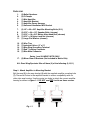
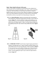
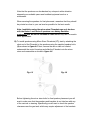
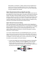
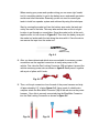
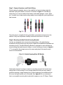
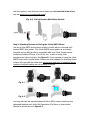
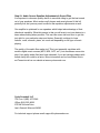
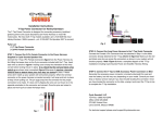
Installation Instructions
Amplified Handlebar Speaker Kits
Note: Audio quality is also dependent upon the device with which the amplifier is
being used with. For best results Cycle Sounds recommends that you use an
audio source with a high millivolt output such as an iPod or modern Smart Phone.
Also adjusting the equalizer for the type of music being played will make your
product work and sound better as well. See STEP-10 for more information.
All Cycle Sounds products have a warranty period of 1 year from the date of
original purchase. This warranty covers the cost of parts only for any needed
repairs to, or replacement of, your unit for 1 year under normal usage. (Labor for
removal or reinstallation of speaker kits and shipping cost are not covered by this
warranty). Any product modified from its original manufactured form or installed
improperly, shall not be covered by this warranty. This does not include
modifications that are required for normal installation as outlined in the
instructions below. Specifically, you should not cut any wires, remove quick
connectors or cut/bend brackets or you risk voiding the manufacturerʼs warranty.
Warranty Notice - When returning products for warranty service a copy of the
original sales receipt or proof of purchase must be sent in the package
accompanying the product. Failure to do so will delay your warranty service.
Warning: The use of a radio, iPod, MP3 player, satellite radio, or any other
device on a motorcycle increases the risk of riding. Riders must always pay
attention while operating their motorcycles. Always make volume and tuning
adjustments when motorcycle is not in motion. Failure to not do so could result in
serious or fatal injuries.
Failing to follow all installation instructions and recommendations carefully can
result in damage to your product, damage to your motorcycle, personal injury or
even death.
Parts List:
1.
2.
3.
4.
5.
6.
(2) Bullet Speakers
(2) P-Clamps
(1) Mini Amplifier
(1) Amplifier Bracket
(1) Amplifier Power Harness
(1) Universal Handlebar MP3 Bracket
7.
8.
9.
10.
11.
(2) 1/4" x 20 x 3/8” Amplifier Mounting Bolts (S.S.)
(2) 5/16” x 24 x 1/2" Speaker Bolts (chrome)
(1) 5/16” x 18 x 3/4" Button Allen Head Bolt (chrome)
(1) 5/16” x 18 Nylon Lock Nut (chrome)
(1) Large Flat Washer (chrome)
12.
13.
14.
15.
16.
(6) Wire Ties
(1) Industrial Velcro (2” x 2”)
(1) Blue Ring Grounding Terminal
(1) Red T Locking Connector
(1) Blue Male Connector
Series 1 and 2 HARLEY KITS ONLY:
17. (2) Mirror Stem Z-Brackets (Not included in Metric Kits)
ALL Road King/Sportster Kits will have (2) of the following (9,10,11)
Step-1: Attach Amplifier to Mounting Bracket
Bolt the amp (3) to the amp bracket (4) with the supplied amplifier mounting bolts
(7). There are 6 holes in the amplifier bracket to ensure compatibility with our
older style amp housing. Use the center two holes to attach the current amplifier
housing as shown in figure 1-1. DO NOT use RED Loctite on these screws.
Fig. 1-1
Step-2: Attach Amplifier Bracket to Motorcycle
There is a few locations the amplifier mounting bracket can be attached and
these locations may vary greatly depending on your make, model and installed
accessories. Most importantly, you need to pay close attention to keep the
amplifier bracket away from the front fender when the suspension is compressed.
This is most often problematic with larger front fenders such as the Road King,
but should be noted on every install to avoid any damage to body panels.
A) On most Harley-Davidson models the amp bracket will mount using the
holes designed for attaching an engine guard (crash bar) on the A frame as
shown in figure 2-1. If there is already an engine guard installed you can
simply unbolt the guard and slip the amp mounting bracket tab behind the
engine guard and reinsert the bolt. If there is no engine guard installed use
the supplied parts (9, 10, 11) to attach the amp bracket as shown in figure
2-2.
Fig. 2-1
Fig. 2-2
B) On a ROAD KING, DO NOT mount the amp using the engine guard bolts or
damage to the fender can occur. Instead, mount the amplifier bracket to the
cross member about 2/3 of the way down the A Frame as shown in figure 23. You may need to pop out the plastic finishing covers if these holes have
never been in use. You may also need to relocate wiring secured to this
location. Use the supplied parts (9, 10, 11) to attach the amp bracket as
shown in figure 2-4.
Fig. 2-3
Fig. 2-4
C) On a Sportster, mount the amp bracket to the bottom of the A frame using
the lower engine guard (crash bar) bolt locations as shown in figure 2-5. If
you have an engine guard installed you will need to detach the bottom 2
bolts to install the amplifier bracket. You may have to slightly enlarge the
amp bracket mounting holes to get the stock bolts to attach the bracket. If
you donʼt have an engine guard installed use the supplied parts (9, 10, 11)
to attach the amp bracket as shown in figure 2-6.
Fig. 2-5
Fig. 2-6
D) On a Metric motorcycle, look at the bolts holding footboards, frame bolts,
engine guard bolts etc. It takes one bolt to mount the universal amplifier
bracket and it is not critical where it is located so long as the amp and wiring
are secure and away from moving parts and high temperatures.
Step-3: Secure Amplifier Harness to Frame
Once the amplifier bracket is attached, secure the amp harness to the frame
using the supplied wire ties (12) making sure to keep wiring away from moving
parts and high temperature heat sources such as the exhaust and engine covers.
Step-4: Attach Speakers to Handlebars
There are a couple of different ways to mount the bullet speakers depending on
what series speakers you are installing and what type of bike is being installed
on. Blue Loctite is always recommended on the speaker bolts so they donʼt
come loose easily.
A) Using P-Clamps: To install speakers using p-clamps (2), separate the 2
halves of the clamps and place around the handlebar in the desired location
(figure 4-1). If you are using the Combo 1-1/4” P-Clamp w/ Shim on a 1”
handlebar simply spread the provided shim around the bar before clasping
the p-clamp around the bar (figure 4-3 & 4-4). Holding the p-clamp together
place the screw through the clamp into the speaker as shown in figure 4-2.
Once in the desired location tighten each speaker mounting screw.
Fig. 4-1
Fig. 4-3
Fig. 4-2
Fig. 4-4
Note that the speakers can be attached to p-clamps in either direction
depending on available space and installed equipment such as a
windscreen.
When securing the speakers for final placement, remember that they should
be pointed as close to your ear level as possible for the best results.
Note: Installation using the mirror stem Z-brackets can only be done
with the Series 1 and Series 2 speakers on a Harley-Davidson
motorcycle and will not be included in other kits as they canʼt be used in
other applications.
B) To install speakers using Mirror Stem Z-brackets (17), start by attaching the
short end of the Z-bracket to the speakers using the supplied speaker bolts
(8) as shown in figure 4-5. Next, remove the mirror stem nut located
underneath the control housings and slide the Z-bracket onto the mirror
stem and reassemble as shown in figure 4-6.
Fig. 4-5
Fig. 4-6
Before tightening the mirror stem bolts for final speaker placement you will
want to make sure that the speakers and brackets do not interfere with any
of the controls or steering. Specifically you will want to check the speaker
clearance near the gas tank, which may require adjustment of the brackets
and speakers on some bikes. To adjust, simply loosen the speaker/mirror
stem bolt and rotate until a suitable location is found. Also make sure the
brackets do not interfere with the throttle control or any other cabling when
turning the handlebar when finished.
Step-5: Route the Speaker Wires and Amplifier Input Wire
Once the speakers are secured on the vehicle route the speaker wires down the
bars making sure to leave enough slack so the wires can be neatly secured when
finished. Also begin routing the amplifier input jack (3.5mm) toward the control
housing or wherever your audio control device will be located (mp3 player). Once
the speaker wires and input wires are routed in a suitable location secure them
using the supplied wire ties (12). When routing the speaker and amplifier wiring
use caution to keep away from pinch points and heat sources.
Step-6: Electrical Connections & Wiring
When connecting power to the amplifier there are a few options depending on
your setup, type of bike and personal preference. We recommend connecting the
power to switched ignition so that the unit is only on when the bike is on. Finding
switched ignition or ʻaccessory powerʼ will be purely dependent upon what
vehicle is being installed on. See below for optional Harley power connection
alternatives for easy installation.
You can use a simple multi-meter to find switched ignition power; or your local
shop or factory service manual should be able to easily identify which wires are
suitable for powering accessories on your model. For this reason, generally it is
not needed to connect an auxiliary fuse or switch, but when doing so use a 5A
fuse and/or most any simple on/off switch if desired.
1. Connect the included Power Harness (5) quick connector to the amplifier
power connector (red/black) as shown in figure 6-1. Route the power
harness toward your accessory power location making sure to leave
enough slack to neatly hide the wiring when finished. Again, make sure to
stay away from pinch points and heat sources as you go.
Fig. 6-1
When running your power and speaker wiring you can use a rigid ʻsnakeʼ
tool (or something similar) to get to the battery area, underneath gas tanks
and around other obstacles. Generally you do not need to remove gas
tanks to install our speaker system and achieved by using this technique.
Start by running the snake tool from the battery area under the tank and
out by the neck of the bike. This may take several tries as this is a tight
location to get through on some bikes. Once the snake tool is at the neck,
tape the wires to it as shown in Figure 6-2. Then from the battery area pull
the snake tool underneath the tank bring the wires with it. Once the wire is
run remove the tape from the snake tool.
Fig. 6-2
2. After you have determined which wires are suitable for accessory power
connection use the supplied connectors to easily wire power to the
vehicle. First, take the Red Locking Connector (15) and place it around the
vehicle accessory power wire as shown in figure 6-3 and press it together
with a pair of pliers until it locks.
Fig. 6-3
3. Then, cut the pin connectors from the end of the power harness and strip
off approximately 1/2" of wire (figure 6-4). Using a pair of suitable wire
crimpers attach the Blue Male Connector (16) to the red wire on the power
harness . Once this is securely connected plug the Blue Male Connector
into the Red Locking Connector as shown in figure 6-5.
Fig. 6-4
Fig. 6-5
4. Last, route the black wire to a good ground location on the vehicle. This
can be on the frame or another ground wire. Crimp the provided Blue Ring
Terminal (14) on the black wire and connect to the ground location on the
vehicle (figure 6-6) or use alternative methods to connect the ground wire.
Fig. 6-6
For Harley Davidson Motorcycles Only:
The power harness comes pre-wired with OEM style terminal connectors that
plug into our optional T-Tap Accessory Connector (p/n: 2120-0026 fits most
Harley-Davidson 1999 to present – p/n: 2120-0027 fits Sportster models
2007 to current) for easy connection of power and ground on most HD models.
Figure 6-7 shows a quick overview of the HD T-Tap connection. Please see the
T-Tap instructions for further explanation. The T-Tap is sold separately and not
included in the kits.
Fig. 6-7
Step-7: Connect Speakers and Finish Wiring
Finish routing the speaker wires to the amplifier and connect them using the
attached 2-pin quick release connectors as shown in figure 7-1. Bundle any
extra wiring so it can be neatly tucked away underneath gauges, covers, lights,
etc. Use wire ties to help secure wiring away from moving parts, pinch points and
heat sources.
Fig. 7-1
Once this step is complete all wiring should be connected and secured on the
vehicle. If they are not please carefully review all instructions to this point.
Step-8: Mounting the Mp3 Switch Housing Bracket
Our kits are designed to be universal and depending on the vehicle being
installed on this procedure may vary and/or require some additional hardware not
included in the kit. The Mp3 Mounting Bracket is designed to work with the top
screw holding the brake reservoir clamp or control housing as shown in figure 81. To accomplish this simply remove the screw and place it through the mp3
mount and reassemble.
(Fig. 8-1) Switch Housing Most HD Models
If the brake reservoir housing is made in a way that prevents the bracket from
sitting flush on the housing or is not facing toward the rider your may need to
purchase a spacer, longer housing bolt or other hardware not included with the
kit to use the mp3 bracket as it is intended. See figure 8-2 for an overview of
how to accomplish mounting the bracket with a spacer or on a P-Clamp. Please
note that spacers, extra bolts and extra clamps are not included in the kit and
may be specific for your make and model.
(Fig. 8-2) Switch Housing Most Metric Models
Step 9: Attaching Devices and Using the 4-Hole AMPS Mount
Use any 4-hole AMPS mount device cradle or holder with the universal mp3
bracket AMPS hole pattern. The 4-hole AMPS mount pattern is an industry
standard and our Mp3 bracket is compatible with most Cycle Sounds device
cradles and holders (iPhone, iPod, Droid, etc.) as well as many other
manufacturersʼ device holders. See figure 9-1 for an example of using the 4-hole
AMPS mount with a cradle holder. Please note that hardware for attaching device
holders will come with the holder and extra screws and nuts for attaching device
cradles to the Mp3 bracket are not included in the kits.
Fig. 9-1
Fig. 9-2
You may also use the included Industrial Velcro (13) to attach small and very
lightweight devices such as the 6th Generation iPod Nano or other similar
devices as shown above in figure 9-2.
Step-10: Audio Source Equalizer Adjustments & Sound Files
It is important to choose a quality device to use while riding to get the best sound
out of your speakers. Most modern mp3 players and smart phones fit this bill
perfectly fine, but you may want to make a few equalizer adjustments as well.
Our amplifier is optimized for our speakers which helps take advantage of their
directional capability. What this means is that you will want to set your device to a
bass reduce setting when possible. This can take some trial and error to get this
just right for your particular setup and device. Generally, settings for bass
reducer, vocal, acoustic, piano, etc. work well depending on the type of music
playing.
The quality of the audio files matter too! This is not generally a problem with
modern digital music sources (MP3, MP4, AIFF, etc.), but sometimes comes into
play if low quality audio files have been obtained. If you are having problems with
sound clarity this could be a factor. More information can be found about this in
an iTunes tutorial on our website at www.cyclesounds.com.
Cycle Sounds® LLC
Toll Free: 1(866) 427-2346
Office: (816) 525-2628
275 NW Victoria Drive
Leeʼs Summit, Missouri 64086
For technical support please email [email protected].