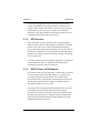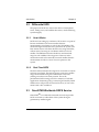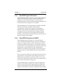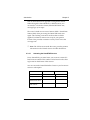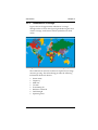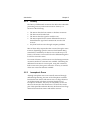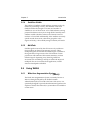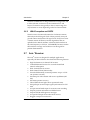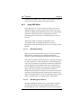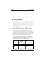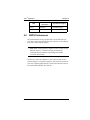
1
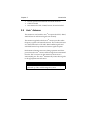
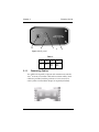
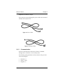
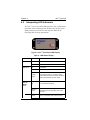
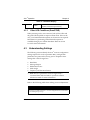
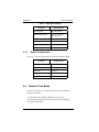
GPS Receiver System Axis 3 TM Operations Manual Part Number 750-1-0060 Rev 2 Copyright Notice Copyright © 2000 POINT, Inc. All rights reserved. No part of this publication or the equipment described in it may be reproduced, translated, stored in a retrieval system, or transmitted in any form or by any means, electronic, mechanical photocopying, recording, or otherwise, without prior written permission of POINT, Inc. Your rights with regard to this publication and the equipment are subject to the restrictions and limitations imposed by the copyright laws of the United States of America (“U.S.A.”) and/or the jurisdiction in which you are located. Trademark Notice Sokkia is a trademark of Sokkia Co. Ltd. All other product and brand names are trademarks or registered trademarks of their respective holders. FCC Notice The equipment described in this manual has been tested pursuant to Part 15 of the FCC Rules and found to comply with the limits for a Class A digital device for use in commercial business, and industrial environments. Operation is subject to the following two conditions: (1) this device may not cause harmful interference, and (2) this device must accept any interference received, including interference that may cause undesired operation. These limits are designed to provide reasonable protection against harmful interference when the equipment is operated in a commercial environment. The equipment generates, uses, and can radiate radio frequency energy and, if not installed and used in accordance with the instruction manual, may cause harmful interference to radio and television reception. Operation of this equipment in a residential area is likely to cause harmful interference in which case the user will be required to correct the interference at his own expense. If this equipment does cause interference to radio or television reception, which can be determined by turning the equipment off and on, you can try to correct the interference by one or more of the following measures: • • • Reorient the receiving antenna. Relocate the receiver relative to the equipment which it interferes. Power the equipment from a different AC receptacle so that this equipment and the interfered equipment are on different branch circuits. If necessary, contact our customer service department or an authorized representative for additional advice. 750-1-0060 Rev 2 October 16, 2000 POINT, Inc.—Advanced Measurement Solutions from Sokkia and NovAtel Contents Chapter 1 Welcome ................................................... 1 1.1 Ports and Icons ............................................................... 1 1.2 Notes, Cautions, and Warnings ................................... 1 1.3 Obtaining Technical Support ....................................... 2 Chapter 2 Introduction .............................................. 5 2.1 Understanding GPS ....................................................... 5 2.1.1 How it Works ...................................................... 5 2.1.2 GPS Services ........................................................ 6 2.1.3 DGPS Format, GPS Standard ............................ 6 2.2 Differential GPS.............................................................. 7 2.2.1 How it Works ...................................................... 7 2.2.2 Real-Time DGPS.................................................. 7 2.3 OmniSTAR Worldwide DGPS Service ....................... 7 2.3.1 OmniSTAR signal information ......................... 8 2.3.2 OmniSTAR Reception and DGPS..................... 8 2.3.2.1 2.3.2.2 2.4 Activating the OmniSTAR Service .............9 Over-Air Subscription Activation.............10 Radio Beacon Service................................................... 11 2.4.1 Radiobeacon Range .......................................... 11 2.4.2 Radiobeacon Messages..................................... 12 2.4.3 Radiobeacon Coverage..................................... 13 2.5 Radio Beacon Position Accuracy ............................... 14 2.5.1 Proximity............................................................ 14 2.5.2 Latency ............................................................... 15 2.5.3 Ionospheric Errors ............................................ 15 2.5.4 Satellites Visible ................................................ 16 2.5.5 MultiPath ........................................................... 16 2.6 Axis 3 Using WAAS................................................................. 16 i Contents 2.6.1 Wide Area Augmentation System ..................... (WAAS)16 2.6.2 WAAS reception and DGPS ............................ 17 2.7 Axis 3 Receiver .............................................................. 17 2.8 Axis 3 Antenna.............................................................. 18 Chapter 3 Receiver Set Up ......................................19 3.1 Receiver Layout and Connections ............................. 19 3.1.1 Connecting Cables ............................................ 20 3.1.2 Communication ................................................. 21 3.2 Installing the Axis 3 Receiver...................................... 22 3.2.1 Environmental Considerations ....................... 22 3.2.2 Connecting Power............................................. 22 3.3 Axis 3 Antenna Guidelines.......................................... 22 3.3.1 Placing Antenna for Optimal Reception........ 23 3.3.2 Routing and Securing the Antenna Cable ..... 23 3.3.3 Connecting the Axis 3 Antenna ....................... 24 3.4 Installing the Data Collector ....................................... 24 3.5 Preparing for Operation .............................................. 24 Chapter 4 Axis 3 Operation......................................27 4.1 Locating Satellites......................................................... 27 4.2 Interpreting LED Indicators........................................ 28 4.2.1 Other LED Conditions (OmniSTAR).............. 29 4.3 Understanding Settings............................................... 29 4.4 Beacon Tune Mode....................................................... 30 4.3.1 Default Configuration ...................................... 30 4.4.1 Using ABS Mode ............................................... 31 4.4.1.1 4.4.1.2 ABS Global Search ......................................31 ABS Background Search.............................31 4.4.2 Using Manual Mode ......................................... 32 ii 4.5 Beacon Performance - SNR Reading ......................... 32 4.6 DGPS Performance....................................................... 33 Axis 3 Contents Appendix A Troubleshooting ..................................... 35 Appendix B Specifications......................................... 36 Appendix C Frequently Asked Questions ................ 41 Axis 3 iii Chapter 1 Welcome Welcome to the Axis 3 Operations Manual and congratulations on purchasing this high performance GPS product from Sokkia. The purpose of this manual is to familiarize you with the proper installation, configuration, and operation of your new receiver. The Axis 3 is a high performance 12-channel GPS receiver with flexible real-time solutions. This integrated product is designed to provide positioning by using corrections from its internal beacon, differential satellite and WAAS sensors to function in a wide array of applications and environments. Compact, lightweight, yet rugged, the Axis 3 receiver will provide you with years of reliable operation. 1.1 Ports and Icons This icon is the symbol for power and identifies the power port, which is located on the rear panel of the Axis receiver. The power port is also referred to in this docu ment as PWR. This icon is the symbol for communications and identifies the communications port, which is located on the rear panel of the Axis receiver. The communications port is also referred to in this document as COM. This icon is the symbol for antenna and identifies the antenna port, which is located on the rear panel of the Axis receiver. The antenna port is also referred to in this document as RF. 1.2 Notes, Cautions, and Warnings Notes, Cautions, and Warnings stress important information Axis 3™ 1 Chapter 1 Welcome regarding the installation, configuration, and operation of the Axis 3 receiver. * Note: Notes outline important information of a general nature. CAUTION Cautions inform of possible sources of difficulty or situations that may cause damage to the product. WARNING Warnings inform of situations that may cause you harm. 1.3 Obtaining Technical Support When contacting customer support, please ensure the following information is available: the product model, serial number and a concise description of the problem. 2 Axis 3™ Welcome Chapter 1 Canada Sokkia Corp. 1050 Stacey Court Mississauga, Ontario L4W 2X8 Phone +1-905-238-5810 Fax +1-905-238-9383 USA Sokkia Corporation 16900 W. 118th Terrace P.O. Box 726 Olathe, KS 66061 Phone +1(913) 492-4900 Fax +1(913) 492-0188 Australia Sokkia Pty. Ltd. Rydalmere Metro Centre Unit 29,38-46 South Street Rydalmere NSW 2116 Australia Phone +61-2-9638-0055 Fax +61-2-9638-3933 Asia Sokkia Singapore Pte. Ltd. 401 Commonwealth Drive #06-01 Haw Par Technocentre Singapore 149598 Phone +65-479-3966 Fax +65-479-4966 U.K. Sokkia Ltd. Datum House, Electra Way Crewe Business Park Crewe, Cheshire, CW1 6ZT United Kingdom Phone +44-1270-25.05.11 Fax +44-1270-25.05.33 Africa Sokkia RSA Pty. Ltd. P.O. Box 7998 Centurion, 0046 Republic of South Africa Phone +27-12-663-7999 Fax +27-12-663-7998 Europe Sokkia B.V. Businesspark De Vaart Damsluisweg 1, 1332 EA Almere P.O. Box 1292, 1300 BG Almere The Netherlands Phone +31-36-53.22.880 Fax +31-36-53.26.241 Central & South America Sokkia Central & South America 1200 N.W. 78 Avenue Suite 109 Miami, FL USA 33126 Phone +1-305-599-4701 Fax +1-305-599-4703 New Zealand Sokkia New Zealand 20 Constellation Drive Mairangi Bay, C.P.O. Box 4464, Auckland 10 New Zealand Phone +64-9-479-3064 Fax +64-9-479-3066 Axis 3™ 3 Welcome Axis 3™ Chapter 1 5 Chapter 2 Introduction This chapter provides a brief overview of the Global Positioning System (GPS), differential GPS (DGPS), beacon and satellite differential and a description of the Axis 3 receiver, antenna, and accessories. 2.1 Understanding GPS The United States Department of Defense (DoD) operates a reliable, 24 hour, all-weather GPS. Navstar, the original name given to this geographic positioning and navigation tool, includes a constellation of 24 satellites (plus active spares) orbiting the Earth at an altitude of approximately 22,000 km. * Note: Selective Availability, SA, was turned off in May 2000. The initial intent of the Department of Defense was to have the ability to degrade the quality of the GPS signal for all non-military users. The resulting positioning accuracy with SA on is from a few meters to 100 meters, however with SA off the positioning accuracy is approximately two to five meters. If there is an immediate danger perceived to the USA, SA may be turned on without review. 2.1.1 How it Works GPS satellites transmit coded information to GPS users at UHF (1.575 GHz) frequencies that allows user equipment to calculate a range to each satellite. GPS is essentially a timing system ranges are calculated by timing how long it takes for the GPS signal to reach the user’s GPS antenna. Axis 3™ 5 Chapter 2 Introduction To calculate a geographic position, the GPS receiver uses a complex algorithm incorporating satellite coordinates and ranges to each satellite. Reception of any four or more of these signals allows a GPS receiver to compute 3D coordinates. Tracking of only three satellites reduces the position fix to 2D coordinates (horizontal with fixed vertical). 2.1.2 GPS Services The positioning accuracy offered by GPS varies depending upon the type of service and equipment available. For security reasons, two GPS services exist: the Standard Positioning Service (SPS) and the Precise Positioning Service (PPS). The US DoD reserves the PPS for use by its personnel and authorized partners. The DoD provides the SPS free of charge, worldwide, to all civilian users. For many positioning and navigation applications, stand-alone or autonomous accuracy is insufficient, and differential positioning techniques must be employed. 2.1.3 DGPS Format, GPS Standard For manufacturers of GPS equipment, commonality is essential to maximize the utility and compatibility of a product. The governing standard associated with GPS is the Interface Control Document, ICD-GPS-200, maintained by the US DoD. This document provides the message and signal structure information required to access GPS. Like GPS, DGPS data and broadcast standards exist to ensure compatibility between DGPS networks and associated hardware and software. The Radio Technical Commission for Maritime Services Special Committee 104 has developed the primary DGPS standard associated with radiobeacon DGPS, designated RTCM SC-104 V2.2. 6 Axis 3™ Introduction 2.2 Chapter 2 Differential GPS The purpose of DGPS is to remove the effects of atmospheric errors, timing errors, and satellite orbit errors, while enhancing system integrity. 2.2.1 How it Works DGPS involves setting up a reference GPS receiver at a point of known coordinates. This receiver makes distance measurements, in real-time, to each of the GPS satellites. The measured ranges include the errors present in the system. The base station receiver calculates what the true range should be, without errors, knowing its coordinates and those of each satellite. The difference between the known and measured range for each satellite is the range error. This error is the amount that needs to be removed from each satellite distance measurement in order to correct for errors present in the system. 2.2.2 Real-Time DGPS The base station transmits the range error corrections to remote receivers in real-time. The remote receiver corrects its satellite range measurements using these differential corrections, yielding a much more accurate position. This is the predominant DGPS strategy used for a majority of real-time applications. Positioning using corrections generated by DGPS radiobeacons will provide a horizontal accuracy of one to five meters with a 95% confidence. 2.3 OmniSTAR Worldwide DGPS Service OmniSTARTM is a worldwide terrestrial service that provides DGPS corrections to subscribers of the system through a geostationary satellite signal. Axis 3™ 7 Chapter 2 2.3.1 Introduction OmniSTAR signal information The OmniSTAR satellite correction is a line-of-sight UHF signal similar to the GPS signal. Various L-Band communications satellites are used for transmitting the correction data to OmniSTAR users around the world. The OmniSTAR signal can be used where beacon signals are not available. The OmniSTAR service uses geostationary satellites (satellites that remain stationary in relation to the earth) for communication. The elevation angle to these satellites is dependent upon latitude. OmniSTAR provides differential coverage over most of the land areas of the globe, with the exception of some areas beyond 60 degrees South Latitude. However, even within the coverage areas, the user must have a clear line-of-sight to the satellite. 2.3.2 OmniSTAR Reception and DGPS The OmniSTAR network functions as a wide-area DGPS service. The information broadcast by the service is based on a network of strategic reference stations. The reference stations communicate GPS correction data to control centers where it is decoded, checked, and repackaged into a proprietary format for transmission to a geostationary L-band communications satellite. This correction data is rebroadcast to the Earth over a large area where an L-band differential receiver demodulates the data. The Axis 3 receiver will process corrections from the wide-area signal specific to your location. The resulting corrections are similar to those calculated if a reference station was set up at your location. This type of solution ensures a consistent level of accuracy across the entire coverage area. The OmniSTAR signal is a proprietary wide-area signal (not RTCM SC-104) with specialized geographically independent formats. Positioning accuracy will not degrade based on the distance to a base station. The data is composed of information 8 Axis 3™ Introduction Chapter 2 from an entire network as opposed to a single base station. When the signal is demodulated by a DGPS receiver, it is converted to a local-area format (standard RTCM SC-104, message Type 1) for input. The Axis 3 L-Band receiver uses a feature called a Virtual Base Station (VBS) when processing the OmniSTAR wide-area signal. The resulting corrections are those that would be applied if a reference station were set up at your present location. This provides consistent accuracy levels across the coverage area. * Note: The GPS receiver inside the Axis 3 provides position information to the L-Band receiver for VBS calculations. 2.3.2.1 Activating the OmniSTAR Service To use OmniSTAR, you must know your receiver’s internal Lband receiver number. This number can be found on the silver tag located on the bottom of the receiver. You can contact the OmniSTAR office closest to your location to receive a subscription. Location Axis 3™ Phone Number Fax Number North America +1-888-883-8476 +1-713-780-9408 Europe/North America +31-70-311-1151 +31-71-581-4719 Asia, Australia, New Zealand, South Africa +61-89-322-5295 +61-8-9322-4164 Central American, South America +1-713-785-5850 +1-713-780-9408 9 Chapter 2 2.3.2.2 Introduction Over-Air Subscription Activation After you contact OmniSTAR, your subscription can be activated on your Axis 3 receiver over the air. The internal DGPS receiver will automatically lock on to the signal even if your subscription has not been activated, however it is of no use to you until your subscription is activated. When you power on the receiver, you must have the antenna in a location with an unobstructed view of the sky. The subscription activation will be transmitted over the air and received by the internal L-band DGPS receiver. To confirm you have a valid and active OmniSTAR subscription, refer to your data collection software reference manual. 10 Axis 3™ Introduction Chapter 2 * Note: Please see the service contract included with the Axis 3 receiver system. 2.4 Radio Beacon Service The Axis 3 receiver is able to use differential corrections received through the internal beacon receiver, operating seamlessly with DGPS beacon networks throughout the world. The receiver uses signals from the United States Coast Guard (USCG), Canadian and all International Association of Lighthouse Authorities (IALA) stations to provide free differential corrections. * Note: The Axis 3 default operation mode is beacon. 2.4.1 Radiobeacon Range The broadcasting range of a 300 kHz beacon is dependent upon a number of factors including transmission power, free space loss, ionospheric state, surface conductivity, ambient noise, and atmospheric losses. The strength of a signal decreases with distance from the transmitting station, due in large part to spreading loss. This loss is a result of the signal’s power being distributed over an increasing surface area as the signal radiates away from the transmitting antenna. The expected range of a broadcast also depends upon the conductivity of the surface over which it travels. A signal will propagate further over a surface with high conductivity than over a surface with low conductivity. Lower conductivity surfaces such as dry, infertile soil, absorb the power of the transmission more than higher conductivity surfaces, such as sea water or arable land. Axis 3™ 11 Chapter 2 Introduction A radiobeacon transmission has three components: a direct line of sight wave, a ground wave, and a sky wave. The line of sight wave is not significant beyond visual range of the transmitting tower, and does not have a substantial impact upon signal reception. The ground wave portion of the signal propagates along the surface of the earth, losing strength due to spreading loss, atmospheric refraction and diffraction, and attenuation by the surface over which it travels (dependent upon conductivity). The portion of the beacon signal broadcast skyward is known as the sky wave. Depending on its reflectance, the sky wave may bounce off the ionosphere and back to Earth causing reception of the ground wave to fade. Fading occurs when the ground and sky waves interfere with each other. The effect of fading is that reception may fade in and out. However, this problem usually occurs in the evening when the ionosphere becomes more reflective and usually on the edge of coverage areas. Fading is not usually an issue with overlapping coverage areas of beacons and their large overall range. Atmospheric attenuation plays a minor part in signal transmission range, as it absorbs and scatters the signal. This type of loss is the least significant of those described. 2.4.2 Radiobeacon Messages Various sources of noise affect beacon reception, and include: • • • • • Engine noise Alternator noise Noise from Power lines DC to AC inverting equipment Electric devices such as CRT’s electric motors, and solenoids Noise generated by this type of equipment can mask the beacon signal, reducing or impairing reception. 12 Axis 3™ Introduction 2.4.3 Chapter 2 Radiobeacon Coverage Figure 1 shows the approximate radiobeacon coverage throughout the world. In this figure, light shaded regions note current coverage, with beacon stations symbolized as white circles. Figure 1: World DGPS Radiobeacon Coverage—April 1999 The world beacon networks continue to expand and coverage areas are growing. The online listing provides the following information about each beacon: • • • • • • • • Axis 3™ Station name Frequency MSK rate Location Transmitting ID Reference station ID Field Strength Operating notes 13 Chapter 2 2.5 Introduction Radio Beacon Position Accuracy Many factors affect the positioning accuracy that a user may expect from a DGPS system. The most significant of these influences include: • • • • • • 2.5.1 Proximity of the remote user to the reference station Age of the received differential corrections Atmospheric conditions at the beacon and remote user locations Satellite geometry, often expressed as a Dilution of Precision (DOP) Magnitude of multipath present at the remote station Quality of the GPS receiver being used at both the reference and remote stations Proximity The distance between a remote user and the reference station is often considerable when using 300 kHz DGPS radiobeacons. Broadcast ranges may be as great as 450 km (280 miles) or more, depending primarily upon transmission power and surface conductivity. Consequently, some of the errors associated with GPS at the base station differ somewhat from those at the remote user’s location. This spatial decorrelation of errors can result in a relative position offset from the absolute coordinates of the remote receiver. This offset may be as much as one meter for every 100 km (62 miles) between the base station and remote receiver. * Note: The OmniSTAR DGPS service is not susceptible to this error because this system uses a wide-area correction format and VBS processing. 14 Axis 3™ Introduction 2.5.2 Chapter 2 Latency The latency of differential corrections also affects the achievable positioning accuracy at the remote receiver. Latency is a function of the following: • • • • • The time it takes the base station to calculate corrections The data rate of the radio link The time it takes the signal to reach the user The time required for the remote differential receiver to demodulate the signal and communicate it to the GPS receiver Any data loss that occurs through reception problems Most of these delays require less than a second, though in some instances, depending upon the amount of information being transferred, overall delays of three to five seconds may occur. Latency can become a concern if lock on the differential signal is lost for ten seconds or more. To account for latency, a GPS receiver can calculate approximate corrections until new corrections are available. Calculating the differential correction for a new epoch, using old corrections, leads to inaccuracy that grows with time. Accuracy is restored when new corrections become available. 2.5.3 Ionospheric Errors Although ionospheric errors are normally removed through differential positioning, the state of the ionosphere can differ between the base station and remote user over large distances. As the base station calculates corrections based on local ionospheric conditions, they may not completely account for the errors observed at the remote user’s location. This causes part of the spatial decorrelation that may be observed over large distances between base station and remote receivers. Axis 3™ 15 Chapter 2 2.5.4 Introduction Satellites Visible The number of satellites visible and their geometry in the sky influences positioning accuracy. The Dilution of Precision (DOP) describes the strength of location and number of satellites in view of the receiver. A low DOP indicates a strong potential for better accuracy than a high DOP. Generally, more satellites visible to both the reference and remote receivers results in a lower DOP. Additionally, if the satellites are evenly spread around the receiver, rather than grouped in a few regions of the sky, a lower DOP (stronger solution) will result. 2.5.5 MultiPath Satellite signals received by the GPS receiver by a reflection from an object can decrease positioning accuracy. These multipath signals increase the measured range to a satellite as the signal takes a longer route to the GPS antenna. Certain precautions will minimize GPS antenna sensitivity to these reflected signals. Operating away from large reflective structures such as buildings can help to reduce the impact of multipath. For most consumer-level applications, a small amount of multipath is tolerable. 2.6 Using WAAS 2.6.1 Wide Area Augmentation System (WAAS) The Wide Area Augmentation System, commonly known as WAAS, is being developed by the Federal Aviation Administration (FAA) as an aid to the basic GPS service. It is specifically designed to provide three-dimensional guidance for airplanes. WAAS, like GPS itself, is yet another tool available to civilian users. 16 Axis 3™ Introduction Chapter 2 WAAS is available free of charge within the coverage area, and it offers real-time corrections for the continental U.S. and beyond. Corrections are typically in the 1-2 meter range, but may be better or worse depending on the local environment. 2.6.2 WAAS reception and DGPS WAAS consists of nationwide networks of reference stations that analyze the GPS signal. Each of these precisely surveyed ground stations analyze the GPS signal to see if any errors exist. A master station calculates correction algorithms that are uplinked to the WAAS satellites, which are then broadcast on the same frequency as GPS (L1, 1575.42MHZ). Receivers within the broadcast coverage area are able to use this signal for position determination. 2.7 Axis 3 Receiver The Axis 3 receiver is designed for multiple applications, especially GIS data collection. It includes the following features: • • • • • • • • • • • • • • Axis 3™ High Performance 12-channel GPS receiver L-Band differential receiver for use with OmniSTAR network subscription Dual- channel beacon receiver Dual-channel WAAS functionality Provides differentially corrected positions at up to a 5 Hz rate (5 times a second) One data port with transmit and receive capabilities (RS232) Sub-meter position accuracy Three LED indicator lights show operational status One-pulse-per-second output signal synchronized to GPS time Accepts manual-mark input for accurate event recording Outputs position information in NMEA format Outputs RTCM and diagnostic messages Accepts RTCM input from other DGPS sources Rugged waterproof construction 17 Chapter 2 • • • 2.8 Introduction Use any power source between 9.5 and 40 Volts DC Cables included One antenna for GPS/L-Band/beacon/WAAS included Axis 3 Antenna The antenna is used with the Axis 3 to acquire the GPS, L-Band, 300 kHz beacon and WAAS signals concurrently. The antenna supplied with the Axis 3 receiver provides radio frequency signals to all internal receivers. The enclosure houses an L-band antenna for GPS and L-Band satellite signals and anH-field beacon loop antenna for beacon signal reception. Both antenna elements are active during operation and draw power from the Axis 3 receiver. All three signals are transmitted from the TNC connector on the antenna to the receiver’s antenna (RF) port. The Axis 3 automatically routes these signals to the appropriate internal sensor. CAUTION Do not connect or disconnect the antenna while the system is powered up. This could damage the system. 18 Axis 3™ Chapter 3 Receiver Set Up This chapter contains instructions and recommendations for the installation of the Axis 3 receiver and antenna. 3.1 Receiver Layout and Connections The Axis 3 receiver is easy to setup and use. Operation requires three items: • • • Antenna cable connection between the receiver and the antenna Antenna location with a clear view to the sky Cable connecting the receiver to camcorder batteries (included) * Note: Using the OmniSTAR satellite corrections requires that a subscription be purchased from OmniSTAR. For more information refer to Chapter 2, Section 2.3.2.2. A data collector is required to communicate with the receiver. Use the Axis 3 receiver with IMap, or other software compatible with the receiver. Communication with the receiver requires the following: • • Axis 3™ A communication cable connecting the receiver and the data collector Baud rate setting on the external device must match the baud rate of the receiver. 19 Chapter 3 Receiver Set Up 1 2 3 4 Figure 1: Back panel Table 1: 1 RF 3.1.1 2 PWR 3 ON/ OFF 4 COM DB9F Connecting Cables Two cables are required to operate and communicate with the Axis 3 receiver (a controller cable and an antenna cable). Both cables are provided with the purchase of a new receiver. In some systems a null modem adapter is required (included). 20 Axis 3™ Receiver Set Up Chapter 3 Figure 2: Null Modem Adapter The system is powered through the power cable and connected directly to the system CPU. Figure 3: Power Cable Figure 4: Antenna Cable 3.1.2 Communication Receiver communication with a data collector is handled through Port A, GPS Port, or an Auxiliary Port. The following data parameters are the same for each port and cannot be changed: • • • Axis 3™ Data bits = 8 Parity = None Stop bits = 1 21 Chapter 3 Receiver Set Up You can adjust the baud rate of each port. Defaults are set as Port A - 9600 baud. Installing the Axis 3 Receiver 3.2 To ensure optimum receiver performance and ease of operation, observe the following considerations when installing the Axis 3 receiver. 3.2.1 Environmental Considerations The Axis 3 receiver is designed to operate in an enclosed environment in which the temperature remains between -30 °C and +70 °C (-22 °F to 158 °F) and relative humidity is less than 95%. The receiver should always be stored between 40 °C and +80 °C (-40°F to 168 °F). * Note: The Axis 3 antenna cannot operate in an enclosed environment. 3.2.2 Connecting Power To power the Axis 3 receiver, connect the single end of the power cable to the PWR port on the rear panel of the Axis 3 receiver and connect the double end of the Y-power cable to the camcorder batteries. The PWR LED,which is located on the front panel of the Axis 3 receiver remains illuminated while power is applied. 3.3 Axis 3 Antenna Guidelines The following sections provide antenna installation details and information on available mounting options. 22 Axis 3™ Receiver Set Up Chapter 3 • Choose a location with a clear, unobstructed view of the sky. • Choose a location that is at least three feet away from all forms of transmitting antennas and communication equipment. • Do not locate the antenna where environmental conditions exceed those specified in Section 3.2.1, on Page 22. 3.3.1 Placing Antenna for Optimal Reception Selecting an appropriate location for installation of the antenna will greatly influence the performance of the receiver. The following list provides some general guidelines for deciding upon an antenna location: • Ensure that the antenna is as far as possible from all other equipment that emits Electromagnetic Interference (EMI), including DC motors, alternators, solenoids, radios, power cables, display units, and other electronic devices. • If a radar is present, mount the antenna outside the path of the radar beam. 3.3.2 Routing and Securing the Antenna Cable The Axis 3 antenna should be used with the TNC-male to TNC-male antenna cable supplied. When choosing a route for the antenna extension cable, consider the following recommendations: • • • • • Axis 3™ Avoid running cables in areas of excessive heat Keep antenna cables away from corrosive chemicals Do not run the extension cable through door or window jams Keep the antenna cable away from rotating machinery Do not bend or crimp the antenna extension cable 23 Chapter 3 • • • Receiver Set Up Avoid placing tension on the cable Remove unwanted slack from the antenna extension cable at the receiver end Secure along the cable route using plastic tie wraps Connecting the Axis 3 Antenna 3.3.3 To connect the antenna to the Axis 3 receiver, connect one end of the antenna cable to the RF port on the rear panel of the Axis 3 receiver, and connect the other end of the antenna cable to the Axis 3 antenna. For more information on antenna connections, see your Axis 3 Jump Start Guide. CAUTION Connect the Axis 3 antenna to the Axis 3 receiver before you apply power to the receiver. 3.4 Installing the Data Collector To establish communications between the Axis 3 receiver and your data collector, connect the data collector to the receiver’s COM port with the data collector’s supplied cable. * Note: For successful communications, the baud rate of the Axis 3 must be set to match that of the data collector. Refer to your data collector manual for instructions related to setting the baud rate. 3.5 Preparing for Operation Before using your Axis 3 receiver, be sure you have done the following: • 24 If you will be using OmniSTAR, be sure that a subscription Axis 3™ Receiver Set Up • • Chapter 3 has been purchased and activated for your receiver. See Section 2.3, OmniSTAR Worldwide DGPS Service, page 6 for more information. If you are using 300 khz beacon capability, make sure you are operating in an area where beacon service is available. When powering on the receiver, wait for the system to locate at least four GPS satellites and to acquire a DGPS solution. * Note: When using the receiver for the first time or in a new area, it may take up to 30 minutes to establish satellite communication and DGPS solutions. Axis 3™ 25 Chapter 4 Axis 3 Operation Operation of the Axis 3 receiver is relatively care free. Your receiver is configured to work right out of the box with most GIS data collection systems like Sokkia’s IMap ΤΜ. This chapter introduces the display features of the receiver’s operating mode and its default operating parameters. 4.1 Locating Satellites GPS Lock .......When the receiver is powered on, it will automatically search for all available GPS satellite signals. A three-dimensional position will be calculated after four satellites are located. This is called GPS Lock. DGPS Lock....Under normal conditions, the Axis 3 receiver will establish a differential lock in about 10 minutes based on the DGPS source (L-Band, WAAS, or 300 khz beacon). The initial DGPS position will be accurate to about one meter and will gradually improve during the first few minutes after DGPS is established. * Note: When using the receiver for the first time or in a new area, it may take up to 30 minutes to establish satellite communication and DGPS solutions. You can monitor the receiver LEDs and your data collection software to determine when a solution has been established. Axis 3™ 27 Axis 3 Operation Chapter 4 4.2 Interpreting LED Indicators The Axis 3 receiver has three LED indicators. You can determine operation status including power, DGPS lock, GPS lock and LBand presence by the color of each indicator. Refer to the following table for more information. Figure 2: Axis 3 Front Panel LED Display Table 2: LED Status Display LED Color Status Description Power Off Power not connected Red Power connected to the receiver Off No GPS lock Yellow GPS lock (about one minute after power on) GPS Lock Blinking Yellow L-Band/ Beacon/ WAAS Lock 28 Differential processor verification will blink three to four times at power up. If it does not blink, possible differential processor failure. Repeated blinking indicates GPS processor failure Off No L-band differential signal Flickering Yellow Receiver is close to acquiring L-band/WAAS differential signal (not applicable when in Beacon mode) Blinking Yellow L-band/WAAS signal acquired, but signal is weak (not applicable when in Beacon mode) Axis 3™ Axis 3 Operation Chapter 4 Table 2: LED Status Display Yellow 4.2.1 L-band/WAAS/Beacon differential signal acquired, locked, and signal is strong Other LED Conditions (OmniSTAR) When powering on the Axis 3 receiver, both yellow LEDs and the green LED may blink in sequence three times. If this is the case, your OmniSTAR subscription on the receiver has expired. Information on purchasing OmniSTAR subscriptions is available through your Sokkia distributor. Refer to section 2.3.2.2 for more information. 4.3 Understanding Settings The following sections identify the Axis 3 receiver configuration settings required for correct operation. Many configuration parameters are preset at the factory prior to shipment. Basic settings that can be changed are: • • • • • Baud Rate Message Output Differential Source Mask Angle Frequency and bit-rate selection * Note: Receiver parameters can be changed with a connected data collector. Refer to your data collector reference manual for more information. Refer to the following table when making receiver adjustments. CAUTION 3 The changes you make to the Axis receiver configuration are saved in memory for subsequent power-up. Axis 3™ 29 Axis 3 Operation Chapter 4 Table 3: Adjustable Settings Parameter 4.3.1 Settings Options Baud Rate (A/B) 4800, 9600, 19200 NMEA Message Output GGA, GLL, VTG, GSV, RMC, GSA, GST Differential GPS source Beacon, L-Band, WAAS Mask Angle 10 degrees (recommended) Frequency/Bit rate Auto, Manual Differential Age Time Out 60 seconds Default Configuration The Axis 3 receiver ships with the following default settings. 4.4 Parameter Default Setting Baud Rate - Port A 9600, 8-N-1, Msg. Off Differential GPS source Beacon Mask Angle 5 degrees Frequency/Bit rate Auto Differential Age Time Out 60 seconds Beacon Tune Mode The Axis 3 receiver can be operated in Automatic or Manual Beacon tune modes. In Automatic Beacon Mode (ABS) the receiver will automatically identify and tune to the station providing the strongest DGPS signal. 30 Axis 3™ Axis 3 Operation Chapter 4 In Manual Tune Mode, you can specify the frequency or select the beacon by name from the built-in global listing. 4.4.1 Using ABS Mode Using ABS, the Axis 3 receiver selects and tunes to the most appropriate beacon without operator intervention. The Axis 3 operates in ABS mode by default and uses its two independent channels to identify and lock to DGPS beacons without interrupting the continuous flow of RTCM data to your GPS receiver. ABS mode is ideal for navigation applications over considerable areas, eliminating the need for operator intervention when switching from one beacon coverage zone to another. 4.4.1.1 ABS Global Search When powered for the first time, the Axis 3 receiver initiates a Global Search, examining each available DGPS beacon frequency, and recording Signal Strength (SS) measurements. The receiver uses these measured values to compute an average SS, and noise floor to sort the frequencies in descending order of SS. The two channels cooperatively examine the frequencies with the highest SS measurements above the computed noise floor to determine the station providing the strongest RTCM signal. The receiver’s primary channel locks to the first identified DGPS broadcast, while the second channel continues searching in the background for superior beacon signals. If no signal is available, the Axis 3 receiver will initiate a fresh Global Search, continuing this cycle until it finds a valid beacon. 4.4.1.2 ABS Background Search During the Background Search, the second channel examines all frequencies at both the 100 and 200 bps Minimum Shift Keying (MKS) bit rates to identify beacons possessing superior Axis 3™ 31 Axis 3 Operation Chapter 4 signal quality. If a DGPS broadcast is identified that exhibits a 2 dB greater signal strength than that of the primary station, the receiver will automatically switch to this beacon. No loss of lock occurs on the primary station during the background scan. The Axis 3 receiver stores the current primary beacon in memory so that it is available upon subsequent power-up. 4.4.2 Using Manual Mode In Manual Tune Mode, you can select a specific frequency and bit rate for the receiver, you can specify the frequency only. Specifying the frequency only allows the Axis 3 to identify the correct MSK rate on its own, which is useful when working in an area where you know the frequency, but not the MSK bit rate of the closest beacon. 4.5 Beacon Performance - SNR Reading The Signal to Noise Ratio (SNR) best describes the beacon receiver performance. The SNR is the height of the signal above the noise floor. The higher the SNR, the better the reception. The SNR can be monitored with your data collector (refer to your data collector reference manual for more information). The following table describes the beacon receiver quality of reception with respect to the SNR reading. You can use your data collection software to set current SNR values. SNR 32 Reception Description Appx. Data Throughput >25 Excellent 100% data throughput 20 to 25 Very Good 100% data throughput 15 to 20 Good Good data throughput up to 100% 10 to 15 Stable Moderate/good throughput Axis 3™ Axis 3 Operation SNR 4.6 Chapter 4 Reception Description Appx. Data Throughput 7 to 10 Intermittent Low data throughput <7 No Lock No data throughput DGPS Performance The OmniSTAR receiver provides both a lock LED and a bit error rate, monitored through the data collector, to describe the lock status and reception quality. * Note: Both of these features depend on line-of-sight access between the Axis 3 antenna and the geostationary communications satellite broadcasting OmniSTAR correction information. The bit error rate has a default, no-lock value of 500. As the receiver begins to acquire the signal, it will result in a lower bit error rate. Optimal performance is achieved when this value is less than 150 and ideally, less than 20. Axis 3™ 33 Appendix A Troubleshooting Use the following checklist to troubleshoot anomalous Axis 3 receiver operation. Table 1 provides a problem symptom, followed by a list of possible solutions. Symptom Axis 3™ Possible Solution Receiver fails to power • Check that the power LED is illuminated • Ensure that batteries are properly charged and connected No data from Axis 3 receiver • Check receiver power status (PWR LED illuminated?) • Verify that Axis receiver is locked to a valid correction source (DGPS LED Illuminated) • Verify that Axis receiver is locked to GPS satellites (GPS LED illuminated) • Check integrity and connectivity of power and data cable connections Random data from 3 Axis receiver • Verify baud rate settings of Axis receiver and data collector No GPS lock • Check integrity of antenna cable • Verify Axis antenna unobstructed view of the sky • Verify antenna cable length < 10 meters • Ensure secure antenna connection • Ensure secure Axis connection No Beacon lock • Check antenna cable connections on both antenna and Axis • Verify MSK rate is set correctly Low SNR • Check integrity of antenna connections • Select alternate antenna position 35 Appendix B Specifications This appendix provides the operational, mechanical, electrical, physical and environmental specifications for the following products: • • Axis 3 receiver Axis Combination antenna Axis Combination GPS/Beacon Receiver Specifications Internal GPS Engine Operational Specifications Item Specification Frequency 1.575 GHz Channels 12 Horizontal Accuracy 1m 95% confidence (DGPS) Internal Beacon Engine Operational Specifications Item Specification Frequency Range 283.5 - 325 kHz Channels 2 Input Sensitivity 1.5 mV/m for 10 dB SNR @ 100 bps MSK Rate Reacquisition Time < 2 Seconds Typical MSK Bit Rate 50, 100, and 200 bps Frequency Selection Manual or Automatic Frequency Offset ± 10 Hz Dynamic Range 100 dB Adjacent Channel Rejection 65 dB ± 1 dB @ f0 ± 400 Hz Decoding RTCM 6/8 Demodulation MSK Axis 3™ 37 Appendix B Specifications Serial Interface Specifications Item Specification Interface Levels RS-232C Data Connector DB9 Socket Data Port Baud Rate 4800, 9600, 19200 Data Output Format RTCM SC-104, NMEA 0183 Data Input Protocol NMEA 0183 Power Specifications Item Specification Input Voltage 9.5 to 48 VDC Power Consumption < 6.5 W Power Connector Circular 2-pin Locking Plug Mechanical Characteristics Item Specification Enclosure Powder-coated aluminum extrusion with powdercoated aluminum front and end plates Length 190 mm (7.48 in.) Width 125 mm (4.9 in.) Height 51 mm (2.0 in.) Weight 0.76 kg (1.68 lb) Antenna Connector TNC Socket Environmental Specifications 38 Item Specification Storage Temperature -40 ºC to + 85 ºC Operating Temperature -32 ºC to + 74 ºC Humidity 95% Non-Condensing Compass Safe Distance 1 m (3.3 ft) Axis 3™ Specifications Appendix B Table 1: Axis Combined Loop / GPS Antenna Specifications Operational Specifications Item Specification Frequency Range, Beacon 283.5 to 325 kHz LNA Gain, Beacon 34 dB Pre-Amplifier, Beacon Integral Low Noise Amplifier Frequency Range, GPS L1 (1575 MHz ± 10 MHz) LNA Gain, GPS 28 dB Power Specifications Item Specification Input Voltage 4.85 to 15.0 VDC Input Current 50-60 mA Mechanical Characteristics Item Specification Enclosure Powder-coated aluminum base, polycarbonate dome Mounting Thread 1-14-UNS-2B Length 129 mm Width 129 mm Height 98 mm Weight 450 g (1.0 lb) Antenna Connector TNC Socket Antenna Extension Cable RG-58U, < 10 m (33 ft) in Length Environmental Specifications Item Specification Storage Temperature -40 ºC to + 85 ºC Axis 3™ 39 Appendix B Specifications Environmental Specifications 40 Operating Temperature -40 ºC to + 85 ºC Humidity 100% Condensing Axis 3™ Appendix C Frequently Asked Questions The following sections contain information on the most common questions encountered when using the Axis 3 receiver. General Question: How do I get OmniSTAR service? Answer: OmniSTAR service is provided through OmniSTAR, Inc. To purchase an OmniSTAR license, contact your Sokkia distributor or visit http://www.omnistar.com. Refer to section 2.3.2.2 for more information. Question: Where is the 300-khz signal available? Answer: The beacon signal is broadcast from transmission stations around the world. Refer to section 2.4.3 for further information. Question: What is WAAS? Answer: WAAS (Wide Area Augmentation System) is a free differential source. WAAS is a network of GPS stations throughout the United States. These stations collect GPS data and solve for differential corrections. The correction data is transmitted via satellite to WAAS enabled GPS receivers. Question: When can I start using WAAS? Answer: The WAAS signal is currently available. Axis 3™ 41 Appendix C Frequently Asked Questions Communication Question: Do I need a 10 Hz output? Answer: No. The Axis 3 receiver’s output rate is 5 Hz, which is suitable for most applications. Many GPS data messages are output less than 1 Hz due to the amount of data being computed and transmitted. A position update of five times per second is considered fast. For more information refer to Specifications in Appendix B of the manual. GPS/DGPS Question: How do I know when my Axis 3 receiver has located a GPS signal? Answer: The easiest way is to look at the LED status indicators on the receiver. See Section 4.2, Interpreting LED Indicators, page 27 for more information. Question: How long does it take to get a DGPS lock? Answer: On normal power-up, you should have DGPS lock within a few minutes. However, if this is the first time your receiver has been powered up in a new region or if the almanac has been reset, DGPS lock can take up to 30 minutes. 42 Axis 3™ Appendix C 43 Frequently Asked Questions Axis 3™ Index A M accuracy, 14, 16 antenna cables, 23 installing, 22 specifications, 38 automatic beacon search (abs), 31 multipath, 16 B background search, 31 baud rate, 24 C cables connectivity, 19 customer support, 2 D R radiobeacon background search, 31 coverage, 13 global search, 31 range, 11 reception, 12 range, 14 range rate, 15 receiver front panel, 28 specifications, 36 RTCM SC-104, 6 S data collector installing, 24 dgps errors, 14 differential corrections, 7 selective availability (sa), 15 signal to noise ratio (snr), 32, 35 specifications antenna, 38 receiver, 36 G T global search, 31, 32 gps beacon service, 11 dgps format, 6 technical assistance, 2 temperature, 22 tune modes H humidity, 22 L LED, 28 Axis 3 43 SOKKIA CO. LTD. INTERNATIONAL DEPT. 20-28, Asahicho 3-Chome, Machida, Tokyo, 194-0023 Japan PHONE +81-42-729-1848 FAX +81-42-729-1930 SOKKIA CORPORATION 16900 West 118th Terrace, P.O. Box 726, Olathe, Kansas, 66061 U.S.A., Phone +1-913-492-4900 Fax +1-913-492-0188 SOKKIA CENTRAL & SOUTH AMERICA CORPORATION 1200 N.W. 78th Avenue, Suite 109, Miami, Florida, 33066 U.S.A., Phone +1-305-599-4701 Fax +1-305-599-470 SOKKIA PTY. LTD. Rydalmere Metro Centre, Unit 29, 38-46 South St., Rydalmere, NSW 2116 Australia, Phone +61-2-9638-0055 Fax +61-2-96383933 SOKKIA NEW ZEALAND 20 Constellation Drive, C.P.O. Box 4464, Mairangi Bay, Auckland 10 New Zealand, Phone +64-9-479-3064 Fax +64-9-479-3066 SOKKIA B.V. Businesspark De Vaart, Damsluisweg 1, 1332 EA Almere, P.O. Box 1292, 1300 BG Almere, The Netherlands, Phone +31-36-53.22.880 Fax +31-36-53.26.241 SOKKIA LTD. Datum House, Electra Way, Crewe Business Park, Crewe, Cheshire, CW1 6ZT United Kingdom, Phone +44-1270-25.05.25 Fax +441270-25.05.33 SOKKIA B.V. Niederlassung Deutschland An der Wachsfabrik 25, 50996 Köln (Rodenkirchen), Germany, Phone +49-2236-39.27.60 Fax +49-2236-6.26.75 BLINKEN A.S., Østkilen 4, Pb122, N-1620 Gressvik, Norway,Phone +4769360910 Fax +47-69360920 SOKKIA S.R.O. Skroupovo námestí 1255/9, 130 00 Praha 3, Czech Republic, Phone +420-2-6273715 Fax +420-2-6273895 SOKKIA S.A. Rue Copernic, 38760 Chasse-sur-Rhóne, France, Phone +33-472.492.640 Fax +33-4-72.492.646 SOKKIA S.R.L. Via Alserio 22, 20159 Milano, Italy, Phone +39-02-66.803.803 Fax +39-02-66.803.804 SOKKIA N.V./S.A. Doornveld, Asse 3, Nr.11-B1, 1731 Zellik (Brussels) Belgium, Phone +32-2-466.82.30 Fax +32-2-466.83.00 SOKKIA KFT., Légszeszgyár u.17., 7622 Pécs, Hungary, Phone +36-72226.636 Fax +36-72-324.636 SOKKIA KOREA CO., LTD. 2Fl. Chungam Bldg, 129-11, Chungdam-dong, Kangnam-ku, Seoul, Republic of Korea, Phone +82-2-514-0491 Fax +82-2514-0495 SOKKIA SINGAPORE PTE. LTD. 401 Commonwealth Drive, #06-01 Haw Par Technocentre, Singapore 149598, Phone +65-479-3966 Fax +65-479-4966 SOKKIA (M) SDN. BHD. Dataran Prima, No.31-3, Jalan PJU 1/42A, 47301 Petaling Jaya, Selangor Darul Ehsan, Malaysia, Phone +60-3-7052197 / 7044240 Fax +60-3-7054069 SOKKIA HONG KONG CO., LTD. Rm.1416 Shatin Galleria,18-24 Shan Mei Street, Fo Tan, New Territories, Hong Kong, Phone +852-2-691-0280 Fax +852-2-693-0543 SOKKIA PAKISTAN (PVT.) LTD. Suite #A-2, 4th Floor, Westland Trade Centre, C-5, Central Commercial Area Blook 7 & 8, K.C.H.S.U. Ltd. Shaheed-e-Millat Road, karachi, Pakistan,Phone +92-21-4313151 / 3 Fax +92-21-4313154 SOKKIA INDIA PVT. LTD. C-25, 2nd Floor, Sector-8, Noida-201301, India Phone +91-011-8-527850 / 525781 Fax +91-011-8-525769 SOKKIA GULF P.O.Box 4801, Dubai, U.A.E., Phone +971-4-368539 Fax +971-4-368549 SOKKIA RSA PTY. LTD. P.O. Box 7998, Centurion, 0046 Republic of South Africa, Phone +27-12-663-7999 Fax +27-12-663-7998 SOKKIA CO., LTD. SHANGHAI REP. OFFICE 11F No.8, Tower 1 Kerry Everbright City, 218 Tian Mu Road West, Shanghai, #200070 Peoples Republic of China, Phone +86-21-63541844 Fax +86-21-63172083