1
M2mpower
Application Guide
M2M Power Application guide
Contents
1
Introduction ................................................................................................................. 4
1.1
Purpose of Guide ................................................................................................ 4
1.2
Who Should Read This Guide?........................................................................... 4
1.3
Prerequisites ....................................................................................................... 4
1.4
Related Documentation....................................................................................... 5
2
Software Features....................................................................................................... 9
2.1
M2mpower Integrated Development Environment .............................................. 9
2.2
PC Specification .................................................................................................. 9
2.3
Overview ............................................................................................................. 9
2.4
The IDE Software .............................................................................................. 10
2.4.1
Installing the IDE Software ........................................................................ 10
2.4.2
Getting Started with IDE ............................................................................ 11
2.4.3
Using the IDE software.............................................................................. 11
2.5
Library Toolbar .................................................................................................. 14
2.5.1
M2mpower IDE.......................................................................................... 15
3
How is the script embedded?.................................................................................... 17
3.1
Environment ...................................................................................................... 17
3.2
Limitations ......................................................................................................... 18
4
Script Interpreter ....................................................................................................... 19
4.1
Overview of the Script Interpreter...................................................................... 19
4.2
Interpreter Language......................................................................................... 19
4.3
Limitations ......................................................................................................... 19
4.4
5 Steps to Application Production ..................................................................... 20
4.4.1
Writing a script........................................................................................... 20
4.5
Script Memory Storage...................................................................................... 21
5
Support...................................................................................................................... 22
6
Intrinsic Function Library ........................................................................................... 23
6.1
Level 1 Functions .............................................................................................. 23
6.2
Level 2 Functions .............................................................................................. 25
6.3
Level 3 Functions .............................................................................................. 25
7
Application examples ................................................................................................ 27
8
Controller Mode......................................................................................................... 28
8.1
Introduction........................................................................................................ 28
8.2
Technical Description of Controller Mode ......................................................... 28
8.2.1
Limitations – restricted functionality........................................................... 29
8.3
Controller Mode Example.................................................................................. 30
8.3.1
Running the Example Script ...................................................................... 31
8.4
Controller Mode Script {Controller_Mode.sc} .................................................... 31
9
Keypad and I2C LCD ................................................................................................ 34
9.1
Introduction........................................................................................................ 34
9.2
Keypad .............................................................................................................. 34
9.2.1
Operation................................................................................................... 34
9.2.2
Set-up ........................................................................................................ 34
9.2.3
Example .................................................................................................... 36
9.3
I2C LCD............................................................................................................. 39
9.3.1
Operation................................................................................................... 39
9.3.2
Set-up ........................................................................................................ 39
9.4
Fixed Cellular Terminal Application {FCT.sc}.................................................... 43
10
Demo Board .......................................................................................................... 47
10.1 Demo Board Information ................................................................................... 47
LZT 123 7588 R2B
2
M2M Power Application guide
10.2 Inputs/Outputs ................................................................................................... 47
10.3 UART’s .............................................................................................................. 48
10.4 Thermistor ......................................................................................................... 48
10.5 Miscellaneous.................................................................................................... 48
10.6 Demo Board Script {Demo_Board.sc}............................................................... 50
11
MBUS - Metering Application ................................................................................ 53
11.1 Overview ........................................................................................................... 53
11.2 MBUS support in Embedded Applications ........................................................ 53
11.3 Implementation.................................................................................................. 53
11.4 Hardware Setup ................................................................................................ 54
11.5 The Script .......................................................................................................... 54
11.6 Testing the Application ...................................................................................... 54
11.7 Flexibility............................................................................................................ 55
11.8 Metering Application Script {MBUS.sc} ............................................................. 56
11.9 References ........................................................................................................ 59
12
Using the Embedded Application TCP/IP Functions for Data Exchange .............. 60
12.1 Overview of Embedded Applications TCP/IP .................................................... 60
12.2 Basic Usage of TCP/IP Features ...................................................................... 60
12.2.1
Protocols ................................................................................................... 60
12.2.2
GPRS Transport for IP .............................................................................. 61
12.2.3
Flow of TCP/IP Operations in a Script....................................................... 61
12.2.4
TCP Connect Operations .......................................................................... 61
12.2.5
Testing Communications over TCP/IP ...................................................... 62
12.3 General Restrictions.......................................................................................... 62
12.4 Resource Restrictions ....................................................................................... 63
12.4.1
Packet Buffers ........................................................................................... 63
12.4.2
IP Fragmentation ....................................................................................... 63
12.4.3
Performance .............................................................................................. 63
12.5 UDP Example Script {UDP_transfer.sc}............................................................ 64
12.6 TCP Example Script {TCP_transfer.sc}............................................................. 66
12.7 TCP Send Function Script {TCP_send.sc}........................................................ 68
12.8 Host Name Resolution ...................................................................................... 69
12.9 IP Status Flags and Bytes ................................................................................. 69
12.10
Advanced Technical Details .......................................................................... 69
12.10.1
Time-to-Live (TTL)................................................................................. 69
12.10.2
DNS Name Caching Period................................................................... 70
13
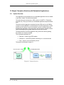
Simple Telematics Solution with Embedded Applications..................................... 71
13.1 System Overview .............................................................................................. 71
13.2 TCS Script Flowchart ........................................................................................ 72
13.3 TCS IFL Support ............................................................................................... 73
13.4 Telematics Core Service Script {TCS_SMS.sc} ................................................ 74
LZT 123 7588 R2B
3
M2M Power Application guide
1 Introduction
The Sony Ericsson M2mpower package provides a powerful support
environment designed to facilitate the development of cost-effective wireless
machine-to-machine or man-to-machine (M2M) applications. M2mpower
enables you to develop innovative new applications and embed them directly
onto Sony Ericsson's M2M products using specifically designed development
tools. Products for use with M2mpower include the GR47/GR48 radio
devices and the GT47/GT48 control terminals.
The M2mpower package includes a radio device and a range of software
and hardware development tools. The script language is based on ANSI C.
The software development tools include application function libraries and
reference applications, whilst the package also includes the hardware
elements required to become operational. In addition, users of the
M2mpower package benefit from comprehensive training and support from
Sony Ericsson.
Note : Except where specifically stated, the term radio device in this guide
refers to any one of the Sony Ericsson products capable of being
programmed with embedded applications using M2mpower.
1.1
Purpose of Guide
The purpose of the guide is to explain the key components that make up the
M2mpower package and to help users develop their own M2M embedded
application to run on Sony Ericsson products.
The guide is intended to support, though not to replace, the detailed training
that is available with the M2mpower package.
The Guide covers the following topics.
1.2
•
Software Features - a detailed description of the M2mpower
Integrated Development Environment (IDE) and the script interpreter.
•
Support - a list of the extensive support that is available for
M2mpower package users.
•
Intrinsic Function Library
•
Application Notes - examples of how to utilize the M2mpower
package to create effective systems applications.
Who Should Read This Guide?
This guide is aimed at manufacturers, system integrators, applications
developers and developers of wireless communication equipment.
1.3
Prerequisites
It is assumed that the person using the M2mpower package has a basic
understanding of the following:
LZT 123 7588 R2B
4
M2M Power Application guide
1.4
•
GSM networking
•
Wireless communication and antennas (aerials)
•
AT Commands
•
RS232
•
Micro controllers and programming
•
Electronic hardware design
Related Documentation
•
Integrator’s Manual.
•
AT Commands Manual.
These documents are included on the CD-ROM supplied with the
Developer’s Kit.
LZT 123 7588 R2B
5
M2M Power Application guide
1.5 Abbreviations and Definitions
Abbreviation
Explanations
AFE
Administrative Front End
AFMS
Audio from Mobile Station
API
Application programmers interface
AT
Command set based on original Hayes standard use to
configure modems. Now extended for GSM and radio
device specific configuration
ATMS
Audio to Mobile Station
CBM
Cell Broadcast Message
CBS
Cell Broadcast Service
CSD
Circuit Switched Data
DCE
Data Circuit Terminating Equipment
DTE
Data Terminal Equipment
DTMF
Dual Tone Multi Frequency
EA
Embedded Application
EA Core
Controlling portion of application that is controlled with
signaling software
EA Customisable
Application specific script for defining the actions to be
taken by the EA Core
EFR
Enhanced Full Rate
EMC
Electro-Magnetic Compatibility
ETSI
European Telecommunication Standards Institute
FR
Full Rate
GDFS
Global Data File System
GPRS
General Packet Radio Service
GPS
Global Positioning System
GSM
Global System for Mobile Communication
HR
Half Rate
HSCSD
High Speed Circuit Switched Data
LZT 123 7588 R2B
6
M2M Power Application guide
I2C
Inter IC bus
I/O
Input/output
IDE
Integrated Development Environment
IFL
Intrinsic Function Library
IP
Internet Protocol
ITU-T
International Telecommunication Union Telecommunications Standardization Sector
ME
Mobile Equipment
MMCX
Micro Miniature Coax
MO
Mobile Originated
MS
Mobile Station
MT
Mobile Terminated
NVM
Non Volatile Memory
OTA
Over The Air
PCM
Pulse Code Modulation
PDU
Protocol Data Unit
RF
Radio Frequency
RFU
Reserved for Future Use
RLP
Radio Link Protocol
RS232
Serial interface standard
RTC
Real Time Clock
RTOS
Real time operating system
SDP
Service Discovery Protocol
Signaling software
Standard run-time GSM software for the radio device
SIM
Subscriber Identity Module
SMS
Short Message Service
SPI
Serial Peripheral Interface
TA
Type Approval
TCM
Telematics Core Module
TCP
Transport Control Protocol
LZT 123 7588 R2B
7
M2M Power Application guide
TCS
Telematics Core Service
UART
Universal Asynchronous Receiver Transmitter
UDP
User Datagram Protocol
LZT 123 7588 R2B
8
M2M Power Application guide
2 Software Features
2.1
M2mpower Integrated Development Environment
Sony Ericsson’s M2mpower Integrated Development Environment IDE is a
powerful software tool that allows you to develop, test and download scripts
to your radio device.
2.2
PC Specification
You will need a machine that meets the following minimum specification to
run the IDE software and transfer scripts to the radio device.
2.3
•
Pentium II MMX
•
10MBytes Free disk space
•
Microsoft Windows® 98 (SE), 2000, XP or NT
Overview
The radio device has an embedded controller process. This allows the
developer to write C-style “scripts” that determine the behavior of the system,
and download them into the radio device. The radio device can then monitor
system events by means of its I/O pins, UART, I2C bus or other interfaces,
and internally request GSM functionality. The controller is embedded within
the radio device’s own microprocessor, making the application script run
alongside the GSM software. Alternatively, the radio device can still be used
as an externally controlled modem.
LZT 123 7588 R2B
9
M2M Power Application guide
2.4
The IDE Software
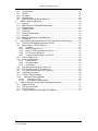
2.4.1 Installing the IDE Software
Insert the M2mpower CD-ROM into your CD drive.
You will see 2 files:
•
M2mpower IDE (MDI).exe
•
M2mpower Application Guide R1A.pdf
•
Select and run M2mpower IDE (MDI).exe
After a few seconds the Sony Ericsson splash screen will be displayed.
Run and type
If the CD-ROM does not auto-run, select Start
D:\M2mpower IDE (MDI).exe into the Run dialogue. (Where D: is your CD
drive.)
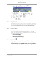
The Install Shield Wizard for Sony Ericsson IDE software opens, follow the
instructions on screen.
When installation is complete a successful installation dialogue is displayed.
LZT 123 7588 R2B
10
M2M Power Application guide
Click Finish to close the dialogue and exit the Install Shield Wizard.
2.4.2 Getting Started with IDE
To launch the Sony Ericsson M2mpower IDE software, click Start
Programs
Sony Ericsson M2M Com
M2mpower IDE (MDI)
M2mpower IDE (MDI). The IDE software workspace opens.
The M2mpower IDE provides a system integrator/developer with a
development environment for writing, debugging and downloading “C-style”
scripts for embedded applications support.
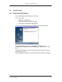
2.4.3
Using the IDE software
Important features of the IDE such as downloading and running scripts can
be accessed via the main toolbar.
LZT 123 7588 R2B
11
M2M Power Application guide
2.4.3.1 To Interpret a Script
The IDE allows a developer to interpret the active script locally with the IDE.
The commands to achieve this are shown in the above diagram. Any results
from running a script locally are shown in the Output Window of the IDE.
2.4.3.2 To Download a Script
The IDE supports two methods of downloading scripts to an embedded
system. Both mechanisms use AT Commands to download scripts. The two
methods of downloading scripts are:
•
Serial Download
•
Remote Download (OTA)
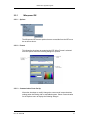
2.4.3.3 Serial Download
The developer must connect the PC running the IDE to the radio device
using a serial connection. All the necessary hardware is contained in the
appropriate Developer’s Kit. Press
to open the Serial Download dialogue
box. Use the dialogue to specify your required download settings.
LZT 123 7588 R2B
12
M2M Power Application guide
2.4.3.4 Remote Download (OTA)
The PC running the IDE can use a modem to set-up a data call to download
a script to a radio device. The data phone number of the SIM associated with
the radio device is required by the IDE when performing remote downloads.
The radio device also requires a script to be running that allows remote
control and auto answering functionality. An example of setting up remote
control for remote download is available from the M2mpower IDE Online
Help, Intrinsic Function Library (IFL).
Press
to open the Enter Data Number dialogue.
When the remote download connection is established the dialogue box
shown above for serial download is displayed with minor differences, namely:
1. The script slot number is automatically set to the non activated slot.
2. The script activation settings are fixed to activate the downloaded script
and set to run from next restart.
3. Once the download is completed and exit pressed, the embedded
application system resets itself and runs the newly downloaded script.
2.4.3.5 To Perform Remote Diagnostic Tests
The IDE allows the developer to perform remote diagnostic tests by sending
AT Commands via data calls (OTA) to an embedded system. This procedure
LZT 123 7588 R2B
13
M2M Power Application guide
is very similar to that of performing remote download. Once the remote
connection has been established, the IDE presents the developer with a
simple text box in which to enter AT Commands. The responses from these
AT Commands are shown in another text box.
2.4.3.6 To Activate a Script
The IDE allows the developer to activate a script from a chosen slot number.
This is achieved using a serial communications link between the PC running
the IDE and the radio device.
2.4.3.7 To Interpret an Embedded Script
The IDE allows the developer to start the interpretation of a previously
downloaded script from a chosen slot number. Similarly the IDE allows the
developer to stop interpreting a running embedded script. Both actions are
achieved using a serial communications link between the PC running the IDE
and the radio device.
2.4.3.8 To Interpret an Embedded Script from Start Up
The IDE allows the developer to enable the interpretation of a previously
downloaded script (in a specified slot) to start from next power up. Similarly,
the developer can disable the interpretation of an embedded script on power
up. Both actions are achieved using a serial communications link between
the PC running the IDE and the radio device.
2.5
Library Toolbar
The library toolbar references all available intrinsic functions from the
Intrinsic Function Library and all interpreter language keywords.
LZT 123 7588 R2B
14
M2M Power Application guide
2.5.1
M2mpower IDE
2.5.1.1 Options
The M2mpower IDE has two options that are accessible from the IDE menu
bar as shown above.
2.5.1.2 Format
This allows the developer to customize the IDE. When Format is selected
from the Options menu the following dialogue is opened.
2.5.1.3 Communication Ports Set Up
Allows the developer to modify/ change the current serial communications
settings when interfacing with an embedded system. Select Communication
for the Options menu to display the following dialogue.
LZT 123 7588 R2B
15
M2M Power Application guide
LZT 123 7588 R2B
16
M2M Power Application guide
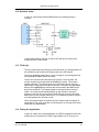
3 How is the script embedded?
3.1
Environment
The controller process sits in the radio device, running within the Real-Time
Operating System that also handles the GSM software processes. The
controller process works in the background, so as not to disturb the GSM
functionality in the radio device.
The controller process uses an interpreter; see “Script Interpreter”, page 18
for more details: The Interpreter reads the script from the NVM area of the
radio device’s storage. The script is interpreted line by line to execute the
required functionality.
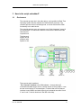
The diagram below shows where the controller process resides in the
system, and the interfaces by which it can communicate with the GSM
software and the hardware interfaces. (The RTOS is the Real-time Operating
System in which all software runs).
There are two main interfaces:
The “Channel” interface to the GSM software – through which AT
commands and data can be sent in a similar manner to using UART1. It can
be seen as an internal AT command port. Functions that use the Channel
interface to send SMS’s and other higher level commands are called “Level
2” and “Level 3” intrinsic functions in the IDE online help.
LZT 123 7588 R2B
17
M2M Power Application guide
The “Drivers” interface to the low level functions. These “drivers” consist of
sets of functions which allow the control of the radio device’s interfaces. The
IDE online help refers to these as “Level 1” intrinsic functions. Interfaces
available include UART, I2C, NVM, SPI, GPIO, ADCs, DAC, TCP/IP (over
GPRS).
“Driver” functions offer direct use of hardware and software functions and are
efficient and fast – generally the lowest level at which you can talk to the
radio device with a script. “Channel” functions, are at a higher level of
abstraction and will take longer to execute.
System events and status are communicated to the script via a set of flags
and bytes. These are set when events occur or the system status changes.
The flags need to be polled by the script in order for the script to react to
system events. An example of a system event is SMS RECEIVED. This is a
“trigger” event which is cleared once the flag is read. INCOMING CALL is a
“state” event which reflects the current status of the radio device. An
example of a system status byte is NETWORK STATUS, which indicates
several types of status e.g. “not connected”, “roaming”.
3.2
Limitations
Operations can have significant latency times. The GSM software is higher
priority than the Application, and so any GSM operation takes precedence. In
times of heavy data activity, the Application may be “switched out” for a
period. If GSM activity is not required, consistent response times can be
obtained by using the Controller Mode functionality.
The scripting language does not support interrupts. Therefore a script should
poll the flags as required.
LZT 123 7588 R2B
18
M2M Power Application guide
4 Script Interpreter
4.1
Overview of the Script Interpreter
The script interpreter transfers a script produced in the IDE to the radio
device. The script interpreter parses the script written in “C” as it is
transferred to the radio device.
The radio device can hold two scripts at any one time, but only one script can
be active.
The script is downloaded to the module using the IDE. When the script is
activated and set to run, the interpreter initializes the available resources,
translates and loads the script from the NVM into RAM, and then parses the
script line by line. Intrinsic function calls in the script are mapped to the
functions available in the module and executed appropriately. The interpreter
runs within the radio device as part of the RTOS as a background level
process, so as not to affect the GSM operation of the device.
4.2
Interpreter Language
The interpreter works as a line based interpreter (similar to BASIC). Syntax is
a limited version of that of C. It allows iterations (while, for), conditional
statements (if. else), functions, pointers, comments, arrays, string literals,
assignment and arithmetic, logical and bitwise operators. It supports two data
types: int (32bit) and char (8bit).
Channel and driver functions are available from the Intrinsic Function Library
(IFL). All radio device specific functions have to be accessed by the IFL. The
IDE online help explains the syntax of each function and details its use.
4.3
Limitations
No floating point arithmetic.
No switch statements.
No typecasting – type checking needs to be done manually to avoid errors.
No “const” or “static” keywords.
Function return type is “int” – not explicitly specified in declaration.
No C++ “\\” style comments – only “/* */” C-style comments.
LZT 123 7588 R2B
19
M2M Power Application guide
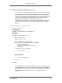
4.4
5 Steps to Application Production
4.4.1 Writing a script
The script needs to be written in a text editor such as that provided in the
IDE. The script must have a main() function, for example:
int val;
main()
{
prtf(“\n Start Script!”);
val = io(0,0,0); /* read IO1 */
prtf(“\n IO1 =%d”, val);
prtf(“\n End Script!”);
}
4.4.1.1 Preliminary debug
The script can be tested in the IDE for a range of errors, including syntax
errors. Functional behavior cannot be tested at this stage.
4.4.1.2 Downloading a script
The script downloaded mechanism as supported by IDE uses two AT
commands – AT*E2APC and AT*E2APD. The download is initiated by
sending the AT*E2APD command with some script information. The radio
device responds, and the script is downloaded using the Xmodem protocol.
For AT Commands details see the AT Commands Manual. Once
downloaded, the script is validated and if successful it can be activated. It
can be run from power up by using AT Commands or via the IDE.
4.4.1.3 Debugging a script on the radio device
Once in the radio device, the script can be debugged using print statements.
The print function allows debug information to be output along with the GSM
logging information on UART2. The GSM logging information can be turned
off to allow easier reading of the debug data. If there is a memory error or
interpreter error when parsing the script, an appropriate error message will
be displayed in the logging information. Error messages are of the from
ERROR#xx: LINExx: <DESCRIPTION>.
4.4.1.4 Script Manipulation and run control
There is the capability for 2 scripts to be stored within the radio device. Only
one script can be active at a time. Only the active script can be started.
When a script is downloaded, the destination slot (0 or 1) is determined.
LZT 123 7588 R2B
20
M2M Power Application guide
Once downloaded, the relevant script slot can be activated. It can then be
run if the other script is not already running.
It is possible to set a script to be run from start up of the radio device. This
option, when selected, will cause the last active script to be run when the
radio device starts up. The reason for having two script slots is that one can
be running while another is downloaded. If the newly downloaded script is
activated, then when the radio device is subsequently reset it will cause the
new script to start running, provided that the new script had been set to run
from start up. This functionality is crucial for OTA script download.
Following the issue of a stop signal, when the interpreter next has control it
will stop the execution of the script and clean up. If the script is executing a
function that takes a long time to return (e.g. TCP connection or a long
delay), the response to the stop command may be an error due to time-out.
The application will stop as long as control is eventually returned to the
interpreter.
4.5
Script Memory Storage
Maximum script size is 350 blocks of 128 bytes (44800 bytes). This space is
shared between the scripts if 2 are present.
The interpreter has 50000 bytes of RAM available to it – this includes
dynamic stack space (fixed size of 20400 bytes), global variable storage, and
all other RAM use. If this size is exceeded an error will occur when trying to
execute on the radio device, as a larger size of memory will not be possible
to allocate. Script memory sizes can be obtained via the IDE.
Since scripts are stored in the form they are written, the size of the script can
be reduced by using short variable and function names, reducing the number
of print statements and removing comments.
LZT 123 7588 R2B
21
M2M Power Application guide
5 Support
IDE and interpreter upgrades will be made available via the extranet solution.
To get access please contact your salesperson.
The M2mpower package provides access to comprehensive group or one to
one training. The training is aimed at Engineers who are already conversant
in ‘C’. The training comprises the implementation of the application to be
embedded onto the radio device, and includes support during the
development phase. Ongoing support will also be available after the
implementation phase.
The key outcomes of the course will be:•
To understand the concept of embedded applications and their use
on the radio device.
•
To become conversant with the IDE.
•
To be able to write, debug and download embedded applications onto
the radio device.
•
To manage TCP/IP communications using an embedded application.
Web based support will provide FAQ's, Technical Description, Training
package, Integrator’s Manual and AT Commands Manual.
Ongoing Product to System level support will be provided throughout the
product lifecycle.
LZT 123 7588 R2B
22
M2M Power Application guide
6 Intrinsic Function Library
The Intrinsic Function Library (IFL) contains a set of built-in functions that are
accessible from a script. The M2mpower IFL contains the following functions,
grouped into categories.
6.1
Level 1 Functions
Debug Library
prtf
Print formatted output to the standard output stream.
Utility Library
itoa
Convert an integer to a string.
atoi
Convert string to integer.
String Library
scat
scmp
scpy
slen
sstr
sncpy
Append a string.
Compare strings.
Copy a string.
Get the length of a string.
Find a substring.
Copy characters of one string to another.
Memory Manipulation Library
mset
memset, set a buffer in memory to a specified value
mcpy
memcpy, copy a number of bytes from one buffer to another
mmve
memmove, move a number of bytes from one buffer to
another
mcmp
memcmp, compare two buffers to each other
General Hardware Library
rc
Remote Control, using a channel set up in a data call.
rst
Resets the module, performing an IMSI detach if necessary.
puct
Configures an IO pin as a pulse counter/reads that pulse
counter.
io
Handles the modules IO pins, allowing configuration, setting
levels, and reading values.
spc
Switches io's used internally by GSM software for general
use and vice versa.
wd
sets and kicks the script watchdog facility
Module Utility Library
dlyms
Delay 50 milli-second intervals.
dlys
Delay 1 second intervals.
prs
Switches on/off modules GSM software log data. Used to
make script debug prints more visible.
pin
Allows entry, re-enable, disable of the SIM PIN (CHV1).
System Status Library
tm
Returns number of system ticks since power on.
LZT 123 7588 R2B
23
M2M Power Application guide
gtf
gtb
Clip
Gets the value (TRUE or FALSE) of a specified system
status flag.
Gets the byte value (0x00 - 0xFF) of a specified system
status byte.
Gets the CLIP (Calling Line Identifier) text to the users
buffer.
Channel Library
chcrt
Create a channel.
chdst
Destroy a channel.
chsts
Get a channel status.
chw
Write data to a channel.
chr
Read from a channel.
M-Bus Driver Library
mxc
Configure the MAX3100 interface (for MBUS).
mxs
Send data to the MAX3100 device, to be output as UART
data.
mxr
Read data from the MAX3100 device, input from external
uart (MBUS) data.
SPI Driver Library
spic
Configure the SPI bus implementation on the IO pins.
spis
Send data over the SPI bus implementation on the IO pins.
I2C Driver Library
i2c
Configure the i2c interface (Change speed).
i2r
Read data from the i2c interface.
i2w
Write data to the i2c interface.
UART Driver Library
utc
Configure the UART3 interface (Open/Close/Set Baudrate).
utr
Read data from the UART3 interface.
uts
Send data to the UART3 interface.
utrl
Return number of bytes buffered on Receive.
utsl
Return number of bytes buffered on Transmit.
Non-volatile Memory (NVM) Library
nvm
Write/ Read from Non-Volatile Memory (NVM).
Database Library
dbadm
Database admin functions (Restore, Create, Destroy).
dbadd
Add record to database instance.
dbget
Retrieve record from database.
dbghd
Get record header.
dbshd
Set record header.
dbfnd
Find record.
dbdel
Delete record.
dbinx
Index database record.
IP Library
pdpa
ipo
ipc
LZT 123 7588 R2B
Activate a PDP context for IP use
Open an IP socket (TCP or UDP)
Close an IP socket
24
M2M Power Application guide
ipi
iprh
udps
udpr
tcpc
tcps
tcpr
Return current IP information (e.g. IP Address)
Resolve Host address to IP address
Send Data via UDP
Receive Data via UDP
Make a TCP connection
Send Data via a TCP connection
Receive Data via a TCP connection
Keypad Control Library
kyc
Keypad Configure
kyd
Keypad Delete
kyr
Keypad Read
Checksum Library
ccrc
Calculate CRC
6.2
Level 2 Functions
AT Command Library
atcrt
Create an AT command channel.
atdst
Destroy an AT command channel.
atsnd
Send AT command get response.
6.3
Level 3 Functions
Short Message Service (SMS) Library
smsi
Initiailise Short Message Service (SMS).
smssc
Set Short Message Service (SMS) Service Centre.
smss
Send Short Message Service (SMS) Message.
smsd
Delete Short Message Service (SMS) Message.
smsrs
Find first Un-read Short Message Service (SMS) Message
from memory.
smsrm
Read Short Message Service (SMS) Message Data.
smsra
Read Short Message Service (SMS) Message Address.
smsrd
Read Short Message Service (SMS) Message Time and
Date Stamp.
Phonebook (PB) Library
pbi
Phone Book Initialise.
pbrtn
Phone Book read number type.
pbrn
Phone Book read number.
pbra
Phone Book read alphanumeric tag.
Global Positioning Satellite (GPS) Library
sirfc
Creates/ Configures UART 3 to send/ receive SiRF Binary/
NMEA Messages.
sirfd
Destroys/ Closes UART 3 from sending/ receiving SiRF
Binary/ NMEA Messages.
sbs
Send a SiRF Binary message to a GPS device.
sbfm
Filter a SiRF Binary Message from a GPS.
snsp
Set GPS device protocol and communication parameters.
LZT 123 7588 R2B
25
M2M Power Application guide
snni
sndgpsp
snqc
snllani
sndev
LZT 123 7588 R2B
Initialise GPS device for a warm start providing position,
clock offset and time.
Set serial port B of GPS device to receive RTCM differential
corrections.
Control the output of standard NMEA messages.
Initialise GPS device for a warm start providing latitude,
longitude, altitude, clock offset and time.
Enable/ Disable development data from GPS device.
26
M2M Power Application guide
7 Application examples
The example applications in this section have been written primarily for the
GR47/GR48 radio devices. The controller mode, TCP/IP and Simple
Telematics applications are also relevant to the GT47/GT48 control
terminals.
Throughout the example applications, any specific radio device signal names
used refer to GR47/GR48 signals.
Where script examples are given, the name of the corresponding IDE
compatible file is given in brackets. These files can be found on the
M2mpower CD-ROM.
LZT 123 7588 R2B
27
M2M Power Application guide
8 Controller Mode
8.1
Introduction
The radio device, when powered up normally, will start up the GSM signaling
software and look to register with a GSM network. The Embedded
Application script runs as a background process, as and when the GSM
software is idle. Controller Mode is a mode of operation whereby the radio
device powers up with a minimal subset of functionality. The GSM signaling
software is halted, and the Embedded Applications script will effectively have
“control” of the processor.
Controller Mode allows an application to run with more predictable response
times. If the GSM functionality is not required for a long period of time, but
some periodic monitoring of IO’s is required, Controller Mode can be used,
giving faster response, lower latency and a more predictable execution time
during Controller Mode, causing the current drawn to maintain a consistent
low level without network dependent fluctuations.
8.2
Technical Description of Controller Mode
The radio device’s mode of operation can only be changed on power up.
Thus, to change the radio device between Normal and Controller Modes, the
radio device is reset. The Embedded Application needs to call the Reset
function (rst()) specifying the mode to reset into – either Normal or Control
Mode. The radio device will then reset into that mode.
When the radio device is reset into Controller Mode:
The radio device performs a software reset, jumping back to the software
start vector and beginning as from a standard power up.
The radio device detects a pattern in flash to indicate that Controller Mode is
required on this power up. Software then initializes only the hardware blocks
that are required for Controller Mode.
The OS initializes and all the processes are initiated. All GSM software
processes and interrupts are disabled, apart from those servicing the
watchdog and essential timer features.
The radio device synchronizes the 13MHz clock to the RTC clock before
switching off the radio circuits and regulators and starting the Embedded
Application.
The script must be setup so that it is run from startup and checks the status
of the mode using a system status flag. This will allow the script to switch
between functionality that works in Controller Mode, and functionality that is
run in Normal mode.
LZT 123 7588 R2B
28
M2M Power Application guide
8.2.1 Limitations – restricted functionality
The operations in Controller Mode are limited to those using the low level
hardware interfaces and simple utility functions. The functions that can be
called in Controller Mode are restricted, due to the fact that the GSM
software is non-operational. A list of the IFL functions and their support in
Controller Mode is given below. For IFL Name Descriptions refer to Appendix
A.
IFL
Name
CM
IFL
Name
CM
IFL
Name
CM
IFL Name CM
IFL
Name
CM
Atcrt
FALSE
Dlyms
TRUE
Mset
TRUE
Scat
TRUE
Snqc
FALSE
Atdst
FALSE
Dlys
TRUE
Mxc
TRUE
Scmp
TRUE
Snsp
FALSE
Atoi
TRUE
Gtb
TRUE
Mxr
TRUE
Scpy
TRUE
Spc
TRUE
Atsnd
FALSE
Gtf
TRUE
Mxs
TRUE
Sirfc
FALSE
Spic
TRUE
Ccrc
TRUE
i2c
TRUE
Nvm
TRUE
Sirfd
FALSE
Spis
TRUE
Chcrt
FALSE
i2r
TRUE
Pbi
FALSE
Slen
TRUE
Sstr
TRUE
Chdst
FALSE
i2w
TRUE
Pbra
FALSE
Smsd
FALSE
Tcpc
FALSE
Chr
FALSE
Io
TRUE
Pbrn
FALSE
Smsi
FALSE
Tcpr
FALSE
Chsts
FALSE
Ipc
FALSE
Pbrtn
FALSE
Smsra
FALSE
Tcps
FALSE
Chw
FALSE
Ipi
FALSE
Pdpa
FALSE
Smsrd
FALSE
Tm
TRUE
Clip
FALSE
Ipo
FALSE
Pin
FALSE
Smsrm
FALSE
Udpr
FALSE
Dbadd
TRUE
Iprh
FALSE
Prs
TRUE
Smsrs
FALSE
Udps
FALSE
Dbadm
TRUE
Itoa
TRUE
Prtf
TRUE
Smss
FALSE
Utc
TRUE
Dbdel
TRUE
Kyc
TRUE
Puct
TRUE
Smssc
FALSE
Utr
TRUE
Dbfnd
TRUE
Kyd
TRUE
Puts
TRUE
Sncpy
TRUE
Utrl
TRUE
Dbget
TRUE
Kyr
TRUE
Rc
FALSE
Sndev
FALSE
Uts
TRUE
Dbghd
TRUE
Mcmp
TRUE
Rst
TRUE
Sndgpsp FALSE
Utsl
TRUE
LZT 123 7588 R2B
29
M2M Power Application guide
8.3
Dbinx
TRUE
Mmve
TRUE
Sbfm
FALSE
Snllani
FALSE
Dbshd
TRUE
Mmve
TRUE
Sbs
FALSE
Snni
FALSE
Wd
TRUE
Controller Mode Example
As a case study, we have an application with the following behaviour:
A system communicates its status by sending a short (16 byte) packet of
data via a serial (RS232) link. This data required to be sent to a host once a
day in order to maintain a central database with details of the system status.
The status packets begin with a byte ‘S’ and end with the byte ‘E’.
Structure of the solution
The radio device could be integrated into the system, connecting UART 3 to
the system’s serial link. The Embedded Application would then read the
status packets in, and batch send them off to the host in an SMS message.
The application is mainly run in Controller Mode, as no GSM activity is
required until the SMS is sent. Once a set number of packets has been
reviewed, or a day has passed (whichever the sooner), the radio device will
then switch back to Normal Mode and send the SMS with the status report.
The radio device then resets to Controller Mode and listens for more status
packets.
(If there is a requirement for a stringent timing on receiving the status
reports, Controller Mode will be necessary in order to give reliable response
time.)
The Application Listing is given at the end of this note. The Application
makes use of a database functionality to store the status reports while in
Controller Mode, so that they can be read and placed into a SMS message
for sending in Normal Mode. Refer to the IDE online help for detailed
descriptions of each of the IFL functions used in this script.
The application script consists of 3 functions:
LZT 123 7588 R2B
•
Main() - called on start-up and determines which mode function is
called.
•
DoControl () - Initializes the database, UART and buffers. Waits for a
packet of data, and once it has been received checks the start and
stop bytes to make sure it is valid report. If so, the report is stored in
the database, and a count is incremented. Once the count reaches
10, or a day has passed since an update was last sent, the radio
device resets into Normal Mode to send the status update.
•
DoGSM() - Restore the database, and reads out each new record,
storing them in the SMS string, before deleting the record. Once all
the records have been transferred, the SMS is sent. The radio device
then resets into Controller Mode and awaits further data.
30
M2M Power Application guide
8.3.1 Running the Example Script
In order to run this example script:
1. Connect the UART3 Tx and Rx lines via an RS232 level shifter to a
COM Port on your PC; you can use the Demo Board for this.
2. Put the script into the Editor, and replace the SMS_NUMBER field with
a valid mobile number you want the SMS reports to be sent to.
3. Download the script, making sure to check the “Run Script on Startup”
box. This will enable the application to run on every startup – crucial for
the functionality with Controller Mode.
4. Run the script. (You can see the debug outputs if you monitor the
UART2 port (115200 baud, 8 data bits, no parity) and set the service
pin HIGH.)
The radio device will have reset into Controller Mode and be waiting for data.
To enter data, use a terminal package and send packets of the form
“SxxxxxxxxxxxxxE” where x is any 7-bit ASCII value. Once 10 valid packets
have been received, or a day has passed, the radio device will reset and
send the data in an SMS to the number you have entered.
8.4
Controller Mode Script {Controller_Mode.sc}
int CONTROLLER_MODE = 11;
int REG_STATUS = 10;
int REGISTERED = 1;
char START_BYTE = 'S';
char STOP_BYTE = 'E';
int CONTROLTIME = 18748800; /* 1 day - time in ticks 217 a second *60*60*24 */
int DATA_PKT_SIZE = 15;
int RECORD_THRESHOLD = 10;
char SMS_NUMBER[13] = “012345678901”; /*replace this with a valid Mobile Phone number*/
int SMSBUFSIZE = (DATA_PKT_SIZE*RECORD_THRESHOLD)+1;
char NEW_FLAG = 0x01;
char Buf[DATA_PKT_SIZE+1];
int db_id = 1;
/*Carry out Controller Mode tasks */
DoControl()
{
int Count = 0;
int recid = 0;
int StartTime = tm();
int TimeExceeded;
mset(Buf,0,DATA_PKT_SIZE+1);
/*restore and open db*/
dbadm(1);
/*destroy all db instances*/
dbadm(2);
/*Create db - db_id should always be 1*/
db_id = dbadm(0);
prtf(“\n New db_id = %d”,db_id);
/*open UART3, 9600 */
utc(1,3);
/*loop looking for incoming packets*/
while(1)
{
/*if at least a packet of data is available*/
if(utrl() >= DATA_PKT_SIZE)
LZT 123 7588 R2B
31
M2M Power Application guide
{
/*read packet*/
utr(Buf,DATA_PKT_SIZE);
prtf(“\n Read packet %s”,Buf);
/* verify packet*/
if((Buf[0] == START_BYTE) && (Buf[DATA_PKT_SIZE -1] == STOP_BYTE))
{
/*Add to db - flag as new */
if(dbadd(db_id,Buf,DATA_PKT_SIZE,NEW_FLAG,0,0) == 0)
{
prtf(“\n Error Adding to DB!”);
}
Count++;
prtf(“\n Count = %d”,Count);
}
}
TimeExceeded = (tm() - StartTime) > CONTROLTIME;
if(TimeExceeded || Count >= RECORD_THRESHOLD)
{
rst(0); /*Start up GSM mode*/
}
prtf(“\n Waiting for Data!”);
dlys(1); /*poll once a second */
}
}
/*Carry Out GSM Tasks*/
DoGSM()
{
char SMS_Buf[SMSBUFSIZE];
int CurrRec = 0;
int CurrLen = 0;
int Len;
prs(0);
/*restore and open db*/
if(dbadm(1) != db_id)
{
/*db error - return to Controller Mode!*/
rst(1);
}
mset(SMS_Buf,0,SMSBUFSIZE);
while(gtb(REG_STATUS) != REGISTERED);
prtf(“\n Registered!”);
/*Send SMS's with IO Data Retrieved*/
CurrRec = dbfnd(db_id,1,0,NEW_FLAG,0,0);
while(CurrRec != 0)
{
Len = dbget(db_id,CurrRec,SMS_Buf + CurrLen);
CurrLen = CurrLen + Len;
if(CurrLen >= SMSBUFSIZE)
{
prtf(“\n Too Much Data!”);
break;
}
dbdel(db_id,CurrRec);
CurrRec = dbfnd(db_id,1,0,NEW_FLAG,0,0);
}
if(slen(SMS_Buf) > 0)
{
int err;
atcrt();
prtf(“\n SMS String = %s”,SMS_Buf);
err = smss(SMS_NUMBER,SMS_Buf,129,slen(SMS_NUMBER),SMSBUFSIZE);
if(err != 0)
{
prtf(“\n Failed sending SMS!”);
}
LZT 123 7588 R2B
32
M2M Power Application guide
atdst();
}
rst(1); /* reset in Controller Mode */
}
/*Main Function*/
main()
{
if(gtf(CONTROLLER_MODE))
{
DoControl();
}
else
{
DoGSM();
}
}
LZT 123 7588 R2B
33
M2M Power Application guide
9
Keypad and I2C LCD
9.1
Introduction
When combined with the embedded applications scripting language,
interfacing a keypad and LCD to the radio device can provide a simple manmachine interface without the need for external host controllers.
Here an application of a fixed-cellular-terminal (FCT) is used to illustrate the
interfacing of a keypad and I2C LCD to the radio device.
Figure 2.1 Application Block Diagram (Fixed cellular terminal)
9.2
9.2.1
Keypad
Operation
When the script executes it calls a key-scan routine in an endless loop.
When no key is pressed the key-scan routine returns the code 0xFF. A keypress is detected when any one of the KeyRow inputs receives a logic low.
The key-scan routine identifies which KeyColumn driver was active when the
key-press was detected and the routine provides a return code representing
the combination of row and column.
9.2.2
Set-up
The keypad driver setup uses the function kyc() to define which rows and
columns are activated for the application. This allows the user to select the
most suitable keypad size and avoids tying up control I/O which would be
more usefully applied elsewhere in the application.
This application example utilizes the full complement of column drivers and
row receivers to provide a 20 key interface.
LZT 123 7588 R2B
34
M2M Power Application guide
Note: The GND ground connection may be used as a column driver. When
used, this is referred to as Column 0.
Figure 2.2 Keypad Interface Schematic
kyc - Keypad Configure
Keypad Configure - initialises specified pins for keypad control
int kyc(char config, char translate);
Return Value:
1 = Success
0 = Failure
Parameters:
LZT 123 7588 R2B
35
M2M Power Application guide
Config
A byte mask of the pins required for the KeyPad - byte assigned as
follows:
For example, the mask 0x7E (0111 1110) would configure rows
(inputs) 1, 2 & 3 and columns (outputs) 2, 3 & 4 (and 0).
Note: Column 0 does not need a value as it is always available.
Translate
0 - Keyread response will be a byte mask
1 - Keyread response will be an integer between 0 and (# of keys -1)
Remark:
This command initialises the keypad. The pins used for the keypad
are Inputs 1-4 and Outputs 1-4. These have to be configured for I/O
use using the relevant io( ) and spc( ) commands before the kyc( )
is called, or else the command will return failure. After creation, the
kyr( ) function can be used.
Note: Column 0 does not require an output pin - it is always
configured. This means that he mask 0xF0 is valid as a 4 row 1
Column (Col 0) key pad.
9.2.3 Example
main()
{
int val;
/*setup All Key pins*/
spc(RI,0); /* turn off RI */
spc(DTR,0); /* turn off DTR */
spc(DCD,0); /* turn off DCD */
spc(DSR,0); /* turn off DSR */
spc(CTS,0); /* turn off CTS */
io(4,KEY_IN2,0); /*switch in I2*/
io(4,KEY_IN3,0); /*switch in I3*/
io(4,KEY_IN4,0); /*switch in I4*/
if(kyc(0xFF,1)) /*maximal keypad, Translate keypress*/
{
prtf(“keypad configured ok = %x”,val);
}
}
Output
keypad configured ok!
kyr - Keypad Read
Keypad Read - returns the current key press as either a byte mask or as
an integer.
int kyr();
LZT 123 7588 R2B
36
M2M Power Application guide
Return Value
Returns value of key press. If no key is pressed the function returns 0xFF.
Note : If the kyc() function had the translate parameter set to 0, kyr() returns
a byte mask showing which row and column are associated with the key
press. (Refer to kyc() for the byte mask definition.)
For example, if kyr() returns 0x24 (0010 0100), this decodes as row (input) 2
and column (output) 3.
If the kyc() function had the translate parameter set to 1, kyr() returns a
number between 0 and (Maximum number of keys - 1). The keys are
numbered from the first row used and the first column used, incrementing
along rows and then columns.
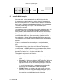
For example, if a keypad is configured with mask 0xE7 (1110 0111), then
key numbers 0 to 11 would be assigned as follows.
Col 0
Col 1
Col 2
Col 3
Col 4
Row 1
-
-
-
-
-
Row 2
0
1
2
3
-
Row 3
4
5
6
7
-
Row 4
8
9
10
11
-
Parameters
None
Remarks
kyr() can only be called after a successful kyc() call. The Keypad is scanned
Example
main()
{
int val;
/*setup All Key pins*/
spc(RI,0); /* turn off RI */
spc(DTR,0); /* turn off DTR */
spc(DCD,0); /* turn off DCD */
spc(DSR,0); /* turn off DSR */
spc(CTS,0); /* turn off CTS */
io(4,KEY_IN2,0); /*switch in I2*/
io(4,KEY_IN3,0); /*switch in I3*/
io(4,KEY_IN4,0); /*switch in I4*/
kyc(0xFF,1); /*maximal keypad, Translate keypress*/
while(1)
{
val = kyr();
if(val != 0xFF)
{
prtf(“key pressed = %x”,val);
}
}
LZT 123 7588 R2B
37
M2M Power Application guide
Output
Key Pressed = xx /*when key is pressed*/
kyd - Keypad Destroy
KeyPad Destroy - disables keypad and frees up used I/O pins
int kyd();
Return Value:
1 = Success
0 = Failure
Parameters:
None
Remarks
This function is called to free up keypad keys to allow reconfiguring of I/Os.
Only valid if the Keypad is active.
Example
if(kyc(0xFF,1);) /*configure maximal keypad */
{
...
val = kyr();
...
if(kyd())
{
prtf(“keypad destroyed!”);
}
}
Output
..Keypad is configured
..Keypad is read
..Keypad is destroyed
keypad destroyed!
LZT 123 7588 R2B
38
M2M Power Application guide
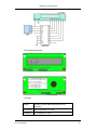
9.3
I2C LCD
9.3.1 Operation
The I2C device used is a general purpose IO controller which is connected to
a parallel port controlled LCD module.
When the script executes, it writes I2C data to set the GPIO chip outputs.
The GPIO outputs are connected to the data and control lines of the LCD
module. The high speed of the I2C data output enables us to create a set of
up to 8 discrete waveforms which meet the requirements of the LCD
electrical interface. The required timings of the LCD interface are provided in
the following pages, along with the I2C LCD interface diagrams and pin-out.
The chosen LCD uses either an 8 bit or a 4 bit data interface with 3
additional control signals RS, E, R/W. We choose to operate the LCD in 4 bit
mode and so can provide the 7 required signals with a single 8 bit I2C-GPIO
converter.
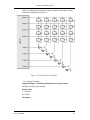
The I2C register has been defined as follows:
BIT
P7
P6
LCD
n/c E
P5
P4
P3
P2
P1
P0
RS
R/W D7
D6
D5
D4
9.3.2 Set-up
The I2C driver uses the function I2C() to set the clock rate for the I2C
interface. There are two rates available, 100kHz and 400 kHz.
This application example uses the 400kHz rate.
The I2C GPIO interface IC is available from Philips Semiconductor and has
manufacturers part number PCT8574A. The address range of the device is
0x70 to 0x7F in hexadecimal notation. For this application we have selected
address 0x70 for writing data and 0x71 for reading data.
To write an 8 bit data instruction to the IC2 port we use the command
i2w(Addr, NumOfBytes, Data, &Ack).
LZT 123 7588 R2B
39
M2M Power Application guide
LCD Interface Schematic
LCD Interface
LCD spec
Supplier
Varitronix Limited (Samsung KS0070B LCD
Controller)
Part Number MDLS16265SSXLV (3 Volt)
Description
LZT 123 7588 R2B
16 Characters x 2 Lines
40
M2M Power Application guide
Pinout
PIN #
NAME
DESCRIPTION
1
VSS
Ground
2
VDD
Logic Supply (2.75V)
3
VO
LCD Supply (0V)
4
RS
Register Select
5
R/W
Read/Write
6
E
Enable
7
DB0
Data0
8
DB1
Data1
9
DB2
Data2
10
DB3
Data3
11
DB4
Data4
12
DB5
Data5
13
DB6
Data6
14
DB7
Data7
15
LED(+)
Backlight Anode
16
LED(-)
Backlight Cathode
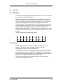
LCD AC Timing Characteristics
Mode
Write
Mode
(Refer to
Fig-2.5)
LZT 123 7588 R2B
Item
Symbo Min
l
Typ Max Unit
E Cycle Time
tc
1400 -
-
E Rise / Fall Time
tr, tf
-
-
25
E Pulse Width (High,
Low)
tw
400
-
-
R/W and RS Setup
Time
tsu1
60
-
-
R/W and RS Hold
Time
th1
20
-
-
Data Setup Time
tsu2
140
-
-
Data Hold Time
th2
10
-
-
E Cycle Time
tc
1400 -
-
ns
41
M2M Power Application guide
Read
Mode
(Refer to
Fig-2.6)
E Rise / Fall Time
tr,tf
-
-
25
E Pulse Width (High,
Low)
tw
400
-
-
R/W and RS Setup
Time
tsu
60
-
-
R/W and RS Hold
Time
th
20
-
-
Data Setup Time
tD
-
-
360
Data Hold Time
tDH
5
-
-
ns
(VDD = 2.7 to 4.5 V, Ta = -30 to +85oC)
Write Mode Timing Diagram
Read Mode Timing Diagram
LZT 123 7588 R2B
42
M2M Power Application guide
9.4
Fixed Cellular Terminal Application {FCT.sc}
char KEY_IN2 = 10;
char KEY_IN3 = 11;
char KEY_IN4 = 12;
char RI = 1;
char DTR = 2;
char DCD = 3;
char DSR = 4;
char CTS = 5;
char CharTable[20] = {1,2,3,0x0a,0x0b,4,5,6,0x0c,0x0d,7,8,9,0x0e,0x0f,0x2a,0,0x23,0x12,0x13};
main()
{
int val, aterr, resCmdSize;
int i; /*counter for keyread loop*/
char resCmd[20];
char resndCmd[30];
char sndCmd[30];
char valstr[2];
char PREVKEYPRESSED = 0;
char CALLING = 0;
/*setup All Key pins*/
spc(RI,0); /* turn off RI */
spc(DTR,0); /* turn off DTR */
spc(DCD,0); /* turn off DCD */
spc(DSR,0); /* turn off DSR */
spc(CTS,0); /* turn off CTS */
io(4,KEY_IN2,0); /*switch in I2*/
io(4,KEY_IN3,0); /*switch in I3*/
io(4,KEY_IN4,0); /*switch in I4*/
valstr[0] = ’\0’;
valstr[1] = ’\0’;
sndCmd[0] = ’\0’; /*NUL terminate send string*/
resndCmd[0] = ’\0’; /*NUL terminate send string*/
aterr = atcrt(); /*AT channel setup */
scpy(sndCmd, “ATD”);
LCDinit(); /*Setup LCD */
val = kyc(0xFF, 1); /*use maximal keyboard*/
while(1)
{
val = kyr();
if(val != 0xFF)
{
if(!PREVKEYPRESSED)
{
PREVKEYPRESSED = 1;
prtf(“key pressed = %x”,val);
val = CharTable[val];
if((val < 0x0a) || (val == 0x2a) || (val == 0x23))
{
if(val <0x0a)
{
itoa(val,valstr,2);
}
else
{
LZT 123 7588 R2B
43
M2M Power Application guide
*valstr = val;
}
LCDdata (*valstr);
scat(sndCmd, valstr);
}
else if(val == 0x0a) /* SEND key*/
{
if(gtb(8)==1) /*incoming call so answer*/
{
aterr = atsnd(“ATA”, resCmd, 3, 20,
&resCmdSize);
LCDcontrol(0x01);
LCDtext(“Answering”, 9);
}
else if(!(gtf(9))) /*outgoing call so dial number*/
{
CALLING = 1;
LCDcontrol(0xc0);
LCDtext(“Dial”, 4);
scat (sndCmd, “;”);
aterr = atsnd (sndCmd, resCmd,
slen(sndCmd), 20, &resCmdSize);
prtf (“\nsent AT command \n%s”, sndCmd);
scpy(resndCmd, sndCmd);
}
}
else if(val == 0x0b) /* REJECT key*/
{
LCDcontrol(0x01);
scpy(sndCmd, “ATD”);
aterr = atsnd (“ATH”, resCmd, 3, 20, &resCmdSize);
}
else if(val == 0x0c) /* REDIAL key*/
{
if(!(gtf(9))) /*outgoing call so dial number*/
{
CALLING = 1;
LCDcontrol(0x01);
LCDtext(“Redial”, 6);
aterr = atsnd (resndCmd, resCmd,
slen(resndCmd),
20, &resCmdSize);
prtf (“\nsent AT command \n%s”, resCmd);
}
}
}
}
else
{
PREVKEYPRESSED = 0;
prtf(“No Key Pressed”);
}
if(gtb(8)==1) /*incoming call so answer*/
{
if(!CALLING)
{
LZT 123 7588 R2B
44
M2M Power Application guide
CALLING = 1;
LCDcontrol(0x01);
LCDtext(“*Incoming Call*”, 15);
}
}
else
{
CALLING = 0;
}
} /* while (1) */
aterr = atdst(); /*destroy AT channel*/
val = kyd(); /*destroy keypad config*/
} /* main */
LCDdata(int Data)
{
char Addr2;
char DataWr[4];
char HiBits;
char LoBits;
char Ack;
Addr2= 0x70;
HiBits = Data >> 4;
LoBits = Data & 0x0f;
DataWr[0] = HiBits | 0x60;
DataWr[1] = HiBits | 0x20;
DataWr[2] = LoBits | 0x60;
DataWr[3] = LoBits | 0x20;
i2w(Addr2,4,DataWr, &Ack);
}
LCDcontrol(int control)
{
char Addr2;
char DataWr[4];
char HiBits;
char LoBits;
char Ack;
Addr2= 0x70;
HiBits = control >> 4;
LoBits = control & 0x0f;
DataWr[0] = HiBits | 0x40;
DataWr[1] = HiBits;
DataWr[2] = LoBits | 0x40;
DataWr[3] = LoBits;
i2w(Addr2,4,DataWr, &Ack);
}
LCDinit()
{
char Addr2;
char DataWr[4];
char Data;
char Ack;
Addr2= 0x70;
i2c(0);
/* Set to 8 bit mode */
/* And Write dummy 8 bit instruction 0001xxxx */
LCDcontrol(0x31);
LZT 123 7588 R2B
45
M2M Power Application guide
/* Set to 4 bit mode and perform initialization */
Data = 0x02;
DataWr[0] = 0x42;
DataWr[1] = 0x02;
i2w(Addr2,2,DataWr, &Ack);
i2w(Addr2,2,DataWr, &Ack);
Data = 0x0c;
DataWr[0] = 0x4c;
DataWr[1] = 0x0c;
i2w(Addr2,2,DataWr, &Ack);
LCDcontrol(0x0f);
LCDcontrol(0x01);
LCDcontrol(0x06);
}
LCDtext(char *textstr, int textlen)
{
char n;
for(n=0; n<textlen; n++)
LCDdata(textstr[n]);
}
LZT 123 7588 R2B
46
M2M Power Application guide
10 Demo Board
The example covered here utilizes a Demo Board that can be plugged into
the Development Board. The Demo Board is preconfigured thus:- LED
jumpers 1-9 are connected, SWITCH jumpers 1-9 are disconnected.
Jumpers I1, O1, O2, O3, O4 are connected, as is ADC1 to the THERM
jumper. All other jumpers are disconnected.
10.1
Demo Board Information
This PCB (Demo Board) is designed as an expansion board to the
Development Board. It plugs into the application connector X3 and
predominantly allows access to the IOs and UART2/3.
10.2 Inputs/Outputs
IO1 to IO9 are each connected to a LED and a switch. Taking IO1 as an
example; if configured as an input, the SW1 jumper needs to be added to
LZT 123 7588 R2B
47
M2M Power Application guide
enable the use of switch IO1 to create an input. If configured as an output,
the LED1 jumper needs to be added to enable the use of LED IO1 as an
output indicator.
O1 to O4 are each connected to a LED. Taking O1 as an example; the O1
jumper needs to be added to enable the use of LED O1 as an output
indicator.
I1 is connected to a switch. The I1 jumper needs to be added to enable the
use of switch I1 to create an input.
Note : A number of the IOs have dual functions. When signals are used on
the Demo Board, you must ensure that they are disconnected from other
circuitry on the Development Board by the removal of the appropriate
jumpers. For example, IO9 is also the UART1 RTS handshaking line. So if it
is used as an IO on the Demo Board the RTS jumper must be removed.
10.3 UART’s
X2 allows access to UART2 at RS232 levels. To enable system-status
logging from the radio device on this port the SRVC jumper needs to be in
place on the Development Board.
X3 allows access to UART3 at RS232 levels. RTS and CTS handshaking
can be implemented on this port through the use of two spare IOs.
Note: When UART2 or UART3 is used on the Demo Board, the TD2/TD3
and RD2/RD3 jumpers on the Development Board must be removed to avoid
conflicts.
10.4 Thermistor
By placing the appropriate jumper across the ADC header, one of the three
ADCs on the radio device can be connected to the onboard thermistor (R43).
10.5 Miscellaneous
A number of other headers are available on the Demo Board. These allow
access to the following signals.
LZT 123 7588 R2B
•
2V7
•
GND
•
3V6_VCC
•
DAC
•
HR_IN
•
ON/OFF
•
RD1
•
SDA
•
SCL
48
M2M Power Application guide
LZT 123 7588 R2B
•
TD1
•
TO_IN
•
UNASSIGNED1
•
UNASSIGNED2
•
UNASSIGNED3
•
UNASSIGNED4
49
M2M Power Application guide
10.6 Demo Board Script {Demo_Board.sc}
When the script runs it configures the IO’s. All the IO’s connected to LED’s
are set as outputs to allow a “bargraph” like display. Input 1 (Switch I1) is
used to switch the script function from “LED_Cascade()” to “ThermalSense”.
When in “LED_Cascade()” mode, the IO’s connected to the LED’s are
toggled so that a reciprocating LED cascade is seen.
When in “ThermalSense” mode, ADC1 reads the voltage at the boards
thermistor, and a relative display of that reading is shown on the LED’s using
the ADCValToIO() function. If a set threshold reading is exceeded, an SMS
is sent to alert of the temperature.
int ADC1 = 17;
int MINLIMIT = 112;
int HYSLIMIT = 120;
int NUMIOS = 13;
char Temp[24] = “Temperature Over Limit!”;
char Number[12] = “012345678912”; /*Enter valid Phone number here*/
char SentAlready = 0;
int Count = 0;
int Up = 0;
char IOS[NUMIOS]= {0,1,2,3,4,5,6,7,8,13,14,15,16};
/* Function Flashes LEDs on IO's up in a LED_Cascade() */
LED_Cascade()
{
/* set direction at endpoints*/
if(Count == (NUMIOS-1))
{
Up = 0;
}
else if(Count == 0)
{
Up = 1;
}
if(Up)
{
/* Set next IO low*/
io(1,IOS[Count++],0);
/* Set Current IO high*/
io(1,IOS[Count],1);
}
else
{
/*Set previous IO low*/
io(1,IOS[Count--],0);
/*Set Current IO high*/
io(1,IOS[Count],1);
}
}
/*Converts the ADC reading to a value that can be displayed on the IO LEDs*/
LZT 123 7588 R2B
50
M2M Power Application guide
ADCValToIO(int Val)
{
char i;
int NewVal = Val;
prtf(“\n Val = %d”,NewVal);
/*Limit the Range to be displayed*/
if(NewVal > 131)
{
NewVal = 131;
}
if(NewVal >= 105)
{
NewVal = NewVal-105;
}
NewVal = (NewVal >> 1); /*divide by 2 to fit in 13 IO's*/
/*NewVal now 0-8*/
/*Set the IO LEDs */
for(i=0;i<NUMIOS;i++)
{
if((i+2) <= NewVal)
{
io(1,IOS[i],0); /*Set IO's*/
}
else
{
io(1,IOS[i],1);
}
}
}
/*Function uses ADC to SHow LED temperature, and sends and SMS if Temperature at
Thermistor is over limit*/
ThermalSense()
{
int Val;
int err;
/*read ADC1 connected to the thermistor*/
Val = io(0,ADC1,0);
/* Set the LEDs to reflect temperature*/
ADCValToIO(Val);
if(Val < MINLIMIT && !SentAlready)
{
prtf(“\n Temp above Max Limit!”);
err = smss(Number, Temp, 129, slen(Number), slen(Temp));
if(!err)
{
SentAlready= 1;
}
}
else if((Val >= HYSLIMIT) && SentAlready)
{
prtf(“\n Temp dropped below Hysteresis Limit!”);
SentAlready = 0;
}
/*Sent Text Alert*/
}
/*Switches between LED_Cascade() and ThermalSense on Input 1 switch
main()
LZT 123 7588 R2B
51
M2M Power Application guide
{
/*For SMS*/
atcrt();
smsi(0,0);
/*io config set up IOs as outputs for LEDs, and Input 1 for switch*/
io(2,0,1); /*IO1*/
io(2,1,1); /*IO2*/
io(2,2,1); /*IO3*/
io(2,3,1); /*IO4*/
io(2,4,1); /*IO5*/
spc(0,0); /*LED - IO6*/
io(2,6,1); /*IO7*/
io(2,7,1); /*IO8*/
spc(6,0); /*RTS - IO9*/
io(2,8,1); /*IO9*/
spc(2,0); /*DTR - Input1*/
spc(1,0); /*RI - O1*/
spc(3,0); /*DCD - O2*/
spc(4,0); /*DSR - O3*/
spc(5,0); /*CTS - O4*/
/*Main loop*/
while(1)
{
/*read Input1*/
if(io(0,9,0) == 1)
{
LED_Cascade();
}
else
{
ThermalSense();
dlyms(2);
}
prtf(“\nlooping!”);
}
}
LZT 123 7588 R2B
52
M2M Power Application guide
11 MBUS - Metering Application
11.1
Overview
This example describes the use of SPI with embedded applications and how
additional components can be added simply to the radio device’s existing
interfaces to provide an extra level of functionality. This is done in the context
of an Application which uses MBUS as its communication mechanism, the
Metering Bus standard (See Ref. 1 of this application note). The script below
uses the Demo Board attached to the Development Board.
11.2
MBUS support in Embedded Applications
MBUS is a standard communications mechanism that covers low and high
layers of the OSI stack model. In order to communicate MBUS packets
physically from one device to another, there is a defined MBUS packet
format. The data has to be sent as 1 start,1stop, 8 data bits and even parity.
To do this, the radio device’s programmable UART3 may be attached to a
MAX3100 SPI-UART IC.
A software SPI implementation is provided that utilizes four I/O pins. This
allows the communication of MBUS data to the MAX3100 SPI-UART IC,
which then constructs the packets into the correct framing with the parity bits.
This then can be communicated to a metering device. The embedded
application has driver function calls for the MAX3100 device that allow simple
configuration of and communication through the device. A further IO line is
used to service interrupts from the MAX3100.
Only the physical layer data framing is done with the driver functions. The
higher layers of the MBUS protocol need to be implemented in the script.
Checking whether the incoming MBUS packets are valid and processing the
buffers is also implemented at script level for complete flexibility.
11.3
Implementation
The example application receives MBUS packets in a data call and sends
them out to any connected metering device. The response packets are then
read in and checked, before being communicated back up the data channel
to the remote host.
LZT 123 7588 R2B
53
M2M Power Application guide
11.4 Hardware Setup
In order to communicate with an MBUS device, the following setup is
required.
A data enabled SIM is required, so that a CSD call can be made from a
remote host to the radio device.
11.5 The Script
The fully commented script listing can be found below. For full descriptions of
the individual script function calls, please refer to the IDE help file.
The script application initially sits in a loop, waiting for an incoming data call
that requests an MBUS session be setup.
Once a call is received and checked to be from the correct number, the
module answers the call and calls the DoMBUS() function. This function
creates a channel. The channel goes to on-line mode and can carry the
MBUS traffic. Data is received from the channel, checked to be valid MBUS
data by the GetMBUSData() function and sent forward to the MBUS slave
device via the M3100. The response data is received (must be received
within 1 sec timeout) and transferred back up the channel in the same
manner. In this way, the remote host can talk with one or more connected
MBUS slaves using a single radio device. The validation procedure ensures
no invalid packets are received or sent.
When the communication is finished, the call is cleared and the channel is
closed down. The script goes back to monitoring for an incoming CSD call to
initiate the next data session.
11.6 Testing the Application
In order to confirm the working application, the RS232 outputs from the level
shifters can be connected via a 9-pin D-type header to a PC Com port. A
LZT 123 7588 R2B
54
M2M Power Application guide
suitable terminal application that can send data in hexadecimal (Hex) can be
used, setting the UART configuration to the MBUS speed and parity settings.
A shareware tool that can be used for Hex transfer is “RS232 Hex Com Tool”
from www.viddata.com. The debug prints from the application can be
monitored if the service pin is asserted on the radio device and UART2 is
monitored at 115200 baud (8 data, 1 start, 1 stop bit). The script field for
DATA_NUMBER will need to be modified to reflect the data calling number.
11.7 Flexibility
This application demonstrates the kind of simple transfer application that can
be written for the radio device, whereby data in some form is received by the
radio device, and is communicated across a different interface to the slave,
and vice versa. All that is required is the code to transfer the data from one
interface to the other. Possible modifications to this script include:
LZT 123 7588 R2B
•
Changing the communication mechanism from CSD to TCP/IP
(GPRS based), or SMS.
•
Changing the interface from MBUS to SPI, standard UART or I2C.
•
Sourcing the data call from the radio device, triggered by an incoming
SMS or call.
55
M2M Power Application guide
11.8
Metering Application Script {MBUS.sc}
/*globals*/
int MAXCFGWORD = 0x2CC4; /* Check this */
int MAXDATA = 30;
int CALL_STATUS = 12;/*byte is status register*/
int RINGING = 1;/*CALL STATUS value*/
char DATA_NUMBER[12] = “07867900940”; /*change this to your number*/
int CALL_COUNT = 1000; /* wait for Data Connection Count */
int GETLOOPCNT = 100; /* check data call status every 100 loops */
int REC10MSCNT = 10; /* 100ms receive wait */
char Recp[261];
char iRec[261];
int st;
/*operates on Recp and iRec*/
GetMBUSData (int RcNotRsp)
{
/*Get MBUS data from Channel or Device*/
/*Contains MBUS packet validation algorithm*/
int Size = 0;
int index = 0;
int di = 0;
int len = 0;
int cnt = 0;
while(st != 0) /*Possibly check on data call status as well?*/
{
if(di >= Size)
{
Size = 0;
if(RcNotRsp > 0)
{
Size = chr(1,iRec,255); /*read more data from channel*/
}
else
{
Size = mxr(iRec,261);
}
di = 0;
}
/*validate the MBUS packet*/
if(Size > 0)
{
Recp[index++] = iRec[di++];
if(Recp[0] == 0xE5)
{
len = 1;
break;
}
else if(Recp[0] == 0x10)
{
if(index >= 5)
{
index = 0;
if(Recp[4] == 0x16)
{
LZT 123 7588 R2B
56
M2M Power Application guide
len = 5;
break;
}
}
}
else if(Recp[0] == 0x68)
{
if(index > 5)
{
int psz = Recp[1];
if(index >= psz + 6)
{
index = 0;
if(Recp[psz + 5] == 0x16)
{
len = psz + 6;
break;
}
}
}
}
else
{
index = 0;
}
}
if( cnt++ < GETLOOPCNT)
{
cnt = 0; /*check call status every 100 loops*/
st = chsts(1) & 0x02;
}
}
if(st == 0)
{
len = 0;
}
return len;
}
DoMBUS()
{
int Sz;
int Cnt = 0;
/*start transmission */
/* get whole MBUS packet from Data Channel */
Sz = GetMBUSData(1);
/* send bytes over uart */
if(mxs(Recp,Sz) == Sz)
{
prtf(“\n Sent data to Max3100”);
}
Cnt = 0;
while(gtf(MAXDATA) == 0 && Cnt < REC10MSCNT)
{
dlyms(2); /*wait 100ms for data*/
prtf(“\n wt resp!”);
Cnt++;
}
if( Cnt < 10)
{
/* receive whole MBUS packet from Max3100 */
LZT 123 7588 R2B
57
M2M Power Application guide
Sz = GetMBUSData(0);
/* send bytes back to data channel */
chw(1,Recp,Sz);
}
else
{
/*no response*/
}
}
main()
{
int InCall = 0;
int NumBuf[13];
int TmpBuf[255];
prs(0);
chcrt(1); /*Create a channel for send/rcv data*/
prtf(“\n Script Created!”);
/* Setup SPI bus and Max3100 interface */
if(mxc(MAXCFGWORD)) /* Enable,Sync High, every 2 bytes*/
{
prtf(“\n Max3100 Configured!”);
}
while (1)
{
int i;
/*wait for incoming call*/
if(gtb(CALL_STATUS) == RINGING)
{
mset(NumBuf,0,13); /*Clear number buffer*/
clip(NumBuf,12); /* get incoming number*/
prtf(“\n Number = %s”,NumBuf);
if(scmp(NumBuf,DATA_NUMBER,12) == 0) /*if number matches*/
{
/*answer call*/
chw(1,"ata\n\r",5);
/* wait for data mode */
for(i=0; i< CALL_COUNT;i++)
{
st = chsts(1);
prtf("\n chsts = %d",st);
if (st & 0x02) /* check second bit of status for DCD */
{
break; /* data carrier detect */
}
dlyms(2); /* wait 100ms */
}
/* clear AT response from channel*/
chr(1,TmpBuf,255);
if(i < CALL_COUNT)
{
/*if count hasn't expired, set to in call*/
prtf(“\n In Call!”);
InCall = 1;
}
}
}
if(InCall)
LZT 123 7588 R2B
58
M2M Power Application guide
{
DoMBUS();
st = chsts(1);
InCall = st & 0x02; /*Make sure still in data call*/
}
else
{
prtf(“\n waiting for Call!”);
dlys(1); /* poll every 1 second when out of call */
}
} /*end while*/
}
11.9
References
1. MBUS - A Documentation - www.m-bus.com
2. MAX3100 Component data sheet - www.maxim-ic.com
LZT 123 7588 R2B
59
M2M Power Application guide
12 Using the Embedded Application TCP/IP Functions for Data
Exchange
12.1
Overview of Embedded Applications TCP/IP
The TCP/IP features provided by the embedded application functions of the
radio device are intended to provide a subset of the features normally
available at the socket level when using a conventional TCP/IP stack, with
some simplification and customization based on the specific features of the
radio device.
The features allow the application-writer to create and destroy UDP and TCP
sockets, to control underlying GPRS PDP contexts, to transfer data to and
from the radio device, and to interrogate IP status information about the
active link.
The socket interface is provided by a series of functions outlined below:
pdpa()
Activate and deactivate a PDP context for TCP/IP over GPRS
ipo()
Open a UDP or TCP socket for data transfer
ipc()
Close a previously opened UDP or TCP socket
tcpc()
Connect to a TCP server specifying IP address and port
tcps()
Send data over a previously connected TCP socket
tcpr()
Receive data over a previously connected TCP socket
udps()
Send data over a UDP socket
udpr()
Receive data over a UDP socket
ipi()
Obtain IP-related information associated with the GPRS link
iprh()
Perform a text-to-IP-address hostname resolution
For full details of these functions, their parameters and possible return
values, refer to the syntax data in the M2mpower IDE Help files.
The majority of the functions, with the exception of the tcpc() function, will
only return once the requested operation is complete. More detail regarding
tcpc() is provided in later sections of this application note.
12.2
Basic Usage of TCP/IP Features
12.2.1
Protocols
The radio device embedded application functions provide support for the IP,
UDP and TCP protocols. The user has no direct control over the IP layer (for
instance a raw sockets interface is not provided), it is simply used as a
transport by the higher-level protocols.
LZT 123 7588 R2B
60
M2M Power Application guide
UDP provides for fast connectionless, less reliable communications between
the radio device and remote hosts; TCP provides slower but reliable,
connection-oriented communications, with flow-control, sequence checking
and reordering.
Whilst the lower-level stack provides support for ICMP (Internet Control
Messaging Protocol) features, and ICMP packets influence the operation and
performance of the lower-level TCP/IP stack, the application-writer has no
direct access to any ICMP features.
12.2.2
GPRS Transport for IP
In order to use the embedded TCP/IP functions, a GPRS PDP context must
be activated first, to provide the underlying IP transport. This should be done
using the pdpa() function, not by using direct AT dial commands. The
embedded applications TCP/IP cannot properly make use of a PDP context
that has been created using the ATD command.
In order to activate a PDP context, the details associated with the context
(such as APN) must have been previously established. This is achieved
using the AT+CGDCONT command. Use of AT commands to define PDP
contexts alongside TCP/IP functions is normal; it is the PDP activation and
deactivation that should not be performed using AT commands.
Once the PDP context is active, a socket can be created to enable bidirectional communications using TCP or UDP.
12.2.3
Flow of TCP/IP Operations in a Script
The basic flow of the TCP/IP operations within a script will normally take the
following form:
1. Define an appropriate PDP context according to Service Provider data
2. Activate the required PDP context
3. Create a socket
4. For TCP only, perform a Connect to a remote host
5. Send data or status information over the socket to a remote host
6. Receive data or status information over the socket from a remote host
7. Repeat steps 5 and 6 for as long as the connection is required
8. Once communications are complete, close the socket
9. Repeat steps 3 to 8 for communications with different remote hosts
10. Deactivate the PDP context
12.2.4
TCP Connect Operations
A TCP connect operation can take quite a long time to complete, depending
upon the link performance, lost packets etc. Therefore the tcpc() function has
been made non-blocking to avoid stalling the script for long periods.
LZT 123 7588 R2B
61
M2M Power Application guide
A call to tcpc() will initiate a connection but return immediately, leaving the
lower level system to connect as responses are received. If no connection is
achieved within a timeout of approximately 75 seconds, an indication of the
failure at the script level will occur when a send or receive is attempted on a
socket for which the connection is not yet active. This means that the
application-writer should do one of two things to ensure that send and
receive operations do not fail because a connection has not yet completed,
either
1. Before a send or receive operation check the connection status by
using the gtb(TCP_STATUS_BYTE) function and checking against
TCP_CONNECTED (where TCP_STATUS_BYTE = 14,
TCP_CONNECTED = 2), or
2. Check the result code from a send or receive operation and if the code
indicates CONNECTING (1) then retry the operation, with appropriate
timeouts applied.
12.2.5
Testing Communications over TCP/IP
The TCP/IP stack supports ICMP operations, such as ping responses these
influence the operation of the low-level stack. However, the application-writer
cannot perform ping tests from within a script. The only method for testing
whether a remote site can be accessed is to attempt either a UDP or TCP
operation to the host.
12.3
General Restrictions
The TCP/IP interface supports a single socket meaning that the embedded
application can have only a single active socket at any one time. Use of, for
instance, a UDP socket and a TCP socket in the same application requires
that the script closes one socket before attempting to open or re-open
another. For the majority of applications, the module is only ever transferring
data over a single socket, so the restriction will not cause problems.
The TCP/IP interface does not currently support a ‘listen’ facility. This means
that the module cannot be configured as a TCP or UDP server waiting for
incoming connections. This restriction has been imposed for three reasons:
1. Most GPRS service providers use Network Address Translation (NAT)
at their access points, which means that incoming IP accesses to the
module will be blocked at the access point, and hence will not be
passed through to the radio device.
2. Where NAT is not used, there are far-reaching security and reliability
implications for systems that offer open services on UDP or TCP ports.
The limited resources within the radio device do not allow for firewall
features to provide full protection against attack vulnerabilities, and the
easiest way to avoid such attacks depleting or destroying a data link is
to disallow unsolicited incoming connections entirely.
3. It is straightforward to provide facilities from the radio device that
equate to a server function, whilst requiring the radio device to instigate
the initial connection to the remote system, i.e. the radio device creates
a socket connection to a remote site after which the remote host issues
LZT 123 7588 R2B
62
M2M Power Application guide
requests to the radio device over the active socket, using the radio
device as a pseudo-server.
12.4
Resource Restrictions
12.4.1
Packet Buffers
The TCP/IP system supports a maximum of six simultaneous packets of size
1-1536 bytes, plus an additional two packets of size 1537-3100 bytes. If,
having assigned all of these buffers, additional packets are received, or
queued for transmit, the packets will be silently dropped. The packet buffers
are shared with the lower-level GPRS system, hence the limits apply to the
total data being buffered within GPRS and TCP/IP software layers.
Due to the buffer considerations, it is strongly recommended to use TCP
rather than UDP to transfer larger volumes of data, or any quantity of critical
data. The likelihood of packet loss within the radio device when using UDP is
quite high, even for infrequent ‘bursts’ of data transfer.
12.4.2
IP Fragmentation
The radio device stack supports IP fragmentation and will successfully
reconstruct fragmented packets provided:
1. No individual fragment exceeds the maximum packet size of 3100
bytes
2. The total reconstructed size of the fragmented packet does not exceed
3100 bytes
3. The internal packet buffers are not exhausted during the period that the
fragments are being received.
The TCP/IP stack will, especially during busy periods, buffer and consolidate
transmit data. This will sometimes result in data being sent from the radio
device in larger units than submitted by the application. However, the largest
sent-packet size will not exceed the reported Maximum Transmission Unit
(MTU) of the underlying link.
12.4.3
Performance
Both the GSM module and the underlying GPRS transport infrastructure
impose performance restrictions that can influence the effective IP
performance of the application such that throughput can not be guaranteed.
LZT 123 7588 R2B
63
M2M Power Application guide
12.5
UDP Example Script {UDP_transfer.sc}
A simple example of a UDP data transfer script is listed below. The script
creates a UDP socket, sends some start data and then sits in a receive loop
until a ‘$’ character is received, after which it closes the socket and exits.
int Err;
int Port = 3000;
int Address = 0x0A8402A3; /* 10.132.2.163 */
int RXTX_SIZE = 1000;
char RxTxBuf[RXTX_SIZE] = “Starting! “;
char Complete = FALSE;
int APPS_IP_ERROR_TRIGGER = 36;
int APPS_IP_ERROR_STATUSBYTE = 13;
int APPS_IP_DATA_RECVD = 13;
int APPS_IP_TCPSTATUS_BYTE = 14;
/* Reset the IP error flag by reading it */
gtf( APPS_IP_ERROR_TRIGGER );
Err = pdpa( 1, 1 );
prtf( "\n PDP activate result = %d\n", Err );
if ( Err == 0 )
{
Val = ipi( 0 );
prtf(" IP Address = %x", Val );
Val = ipi( 1 );
prtf( "\n DNS 1 = %x", Val );
Val = ipi( 2 );
prtf( "\n DNS 2 = %x\n", Val );
}
else
{
prtf( "\n PDP activation failed!\n" );
return;
}
Err = ipo( 0, &SckNum );
if( Err != 0 )
{
prtf( “ \n UDP Socket open failed!\n” );
}
else
{
int len;
prtf( "\n UDP Socket Opened!\n" );
prtf( "\n Sending start data...\n" );
len = 10;
Err = udps( SckNum, Port, Address, RxTxBuf, len );
while( !Complete && (gtb( APPS_IP_ERROR_STATUSBYTE ) == 0) )
{
/* Receive some data */
if( gtf( APPS_IP_DATA_RECVD ) )
{
prtf( "\n IP DATA RECVD" );
len = RXTX_SIZE;
Err = udpr( SckNum, &Port, &Address, RxTxBuf, RXTX_SIZE, &len );
if( Err != 0 )
LZT 123 7588 R2B
64
M2M Power Application guide
{
prtf( "\n UDP receive error!\n" );
}
}
else
{
prtf( “\nReceived %d bytes of data.\n”, len );
if ( RxTxBuf[0] == ‘$’ )
{
prtf( “\n Breaking out of receive loop!\n” );
Complete = TRUE;
}
}
}
/* Log status monitoring */
if( gtf( APPS_IP_ERROR_TRIGGER ) )
{
prtf( "\n IP ERROR = %d\n", gtb( APPS_IP_ERROR_STATUSBYTE ) );
}
}
Err = ipc( SckNum );
if ( Err != 0 )
{
prtf( “\n Socket close failed!\n” );
}
Err = pdpa( 0, 1 );
prtf( "\n PDP deactivate result = %d\n", Err );
LZT 123 7588 R2B
65
M2M Power Application guide
12.6
TCP Example Script {TCP_transfer.sc}
A simple example of a TCP data transfer script is listed below. The script
creates a TCP socket, connects to a remote site and then sits in a receive
loop until a ‘$’ character is received, after which it closes the socket and
exits.
int Err;
int PORTNUM = 3000;
int IPADDRESS = 0x0A8402A3; /* 10.132.2.163 */
int RXTX_SIZE = 1000;
char RxTxBuf[RXTX_SIZE] = “Starting! “;
char Complete = FALSE;
int APPS_IP_ERROR_TRIGGER = 36;
int APPS_IP_ERROR_STATUSBYTE = 13;
int APPS_IP_DATA_RECVD = 13;
int APPS_IP_TCPSTATUS_BYTE = 14;
int TCP_NOT_CONNECTED = 1;
int TCP_CONNECTING = 2;
int TCP_CONNECTED = 3;
/* Reset the IP error flag by reading it */
gtf( APPS_IP_ERROR_TRIGGER );
Err = pdpa( 1, 1 );
prtf( "\n PDP activate result = %d\n", Err );
if ( Err == 0 )
{
Val = ipi( 0 );
prtf( " IP Address = %x", Val );
Val = ipi( 1 );
prtf( "\n DNS 1 = %x", Val );
Val = ipi( 2 );
prtf( "\n DNS 2 = %x\n", Val );
}
else
{
prtf( "\n PDP activation failed!\n" );
return;
}
Err = ipo( 1, &SckNum );
if( Err != 0 )
{
prtf( “ \n TCP Socket open failed!\n” );
}
else
{
prtf( "\n TCP Socket Opened!\n" );
Err = tcpc( SckNum, Port, Address );
if( (Err == 0) || (Err == TCP_CONNECTING) || (Err == TCP_CONNECTED) )
{
while( !Complete && (gtb( APPS_IP_ERROR_STATUSBYTE ) == 0) )
{
int len;
/* Receive some data */
if( gtf( APPS_IP_DATA_RECVD ) )
{
prtf( "\n IP DATA RECVD" );
len = RXTX_SIZE;
Err = tcpr( SckNum, RxTxBuf, &len);
if( Err != 0 )
{
LZT 123 7588 R2B
66
M2M Power Application guide
prtf( "\n *** Error in TCP Receive (%d). ***\n\n", Err );
}
else
{
if( gtb( APPS_IP_TCPSTATUS_BYTE ) == TCP_CONNECTING )
{
prtf( "\n Delaying while TCP Connect occurs...\n\n" );
}
else
{
prtf( "\n Received %d bytes of data.\n\n", len );
}
}
}
/* Log status monitoring */
if( gtf( APPS_IP_ERROR_TRIGGER ) )
{
prtf( "\n IP ERROR = %d\n", gtb( APPS_IP_ERROR_STATUSBYTE ) );
Complete = 1;
}
if( gtb( APPS_IP_TCPSTATUS_BYTE ) == TCP_NOT_CONNECTED )
{
prtf( "\n *** TCP Connection lost - dropping out! ***\n\n" );
Complete = 1;
}
}
}
Err = ipc( SckNum );
if ( Err != 0 )
{
prtf( “\n Socket close failed!\n” );
}
}
Err = pdpa( 0, 1 );
prtf( "\n PDP deactivate result = %d\n", Err );
LZT 123 7588 R2B
67
M2M Power Application guide
12.7
TCP Send Function Script {TCP_send.sc}
It is important to note that when using tcps(), the intrinsic TCP send function,
the application-writer must check the number of bytes sent on successful
return from the function, because a successful return is possible with the
number of bytes actually sent being less than the number requested. In this
case it is the responsibility of the application-writer to ensure that the
remainder of the data buffer is re-submitted to the function.
The following is an example of a TCP send script function that checks for
and corrects problems when not all data requested is sent by the tcps()
function.
TCPSend( char cSckNum, char *cpTxBuffer, int *ipLen )
{
int MAX_TX_ATTEMPTS = 20;
int TX_FAILED = -2;
int TCP_BACKOFF_DLYS = 2;
int iResult = 0, iInitLen = *ipLen, iSent = 0, iTxAttempts = 0;
int iReqLen;
char *cpBuffer;
while ( (iSent != iInitLen) && (iResult == 0) )
{
iReqLen = iInitLen - iSent;
cpBuffer = cpTxBuffer + iSent;
iResult = tcps( cSckNum, cpBuffer, &iReqLen );
while ( (iResult != 0) && (iTxAttempts < MAX_TX_ATTEMPTS) )
{
dlys( TCP_BACKOFF_DLYS );
iResult = tcps( cSckNum, cpBuffer, &iReqLen );
iTxAttempts++;
}
if ( iTxAttempts >= MAX_TX_ATTEMPTS )
{
return TX_FAILED;
}
iSent = iSent + iReqLen;
if ( iSent != iInitLen )
{
dlys( TCP_BACKOFF_DLYS );
}
iTxAttempts++;
}
return iResult;
}
The parameters for the call to TCPSend are the same as for tcps(), but the
length parameter is an input only. The function will not return until either all
the data has been sent, or a failure has occurred. Obviously the values for
back-off delay and transmission retries can be adjusted to suit the
application.
LZT 123 7588 R2B
68
M2M Power Application guide
This function assumes that the caller has already checked that the TCP
socket is connected, or if not, that the connection will become active within
the timeout/retry period.
12.8 Host Name Resolution
Host name resolution in a script is performed using the iprh() function. The
application-writer should be aware that the name lookup is effectively a
blocking function. The script interpreter process will be blocked until the
lookup is completed. This can lead to long script processing delays if
something with the name resolution fails.
The name servers used by the lower-level stack are usually obtained
dynamically when a PDP context is activated. The active settings can be
interrogated using the ipi() function. A DNS lookup has a minimum timeout of
approximately 124 seconds. Hence if all DNS servers are inaccessible (up to
3 are supported), or if the domain name does not resolve, there can be an
overall delay of between 125 and 140 seconds before the iprh() function
returns. During this delay script operation will stall, therefore the use of
unreliable DNS servers could cause long pauses in operation.
12.9
IP Status Flags and Bytes
There are two status bytes and one status flag associated with the TCP/IP
features. These are interrogated using the gtb() and gtf() script functions
respectively.
The IP status flag APPS_IP_ERROR_TRIGGER (36) is set whenever an
error occurs in the lower level IP system. The flag remains set until it is read,
and is reset upon reading. The error that gave rise to the flag is obtained by
reading the status byte APPS_IP_ERROR_STATUSBYTE (13). If several IP
errors occur before the status flag is set the last error will be reported in the
status byte.
The TCP system has a separate status byte called
APPS_IP_TCPSTATUS_BYTE (14) which reports the current status of the
TCP connection. This status can indicate that TCP is not-connected,
connecting, or connected.
12.10
Advanced Technical Details
This section lists a number of advanced technical points for users who wish
to understand more of the fine details of the TCP/IP stack in the radio device.
For most readers this information will not be relevant.
12.10.1
Time-to-Live (TTL)
The radio device IP stack uses a Time-to-Live (TTL) setting of 64. This figure
is fixed as far as the application-writer is concerned; there is no high-level
method for changing it. Many modern systems use a TTL of 128, but apart
from the most complex of routing arrangements, a figure of 64 will be
perfectly adequate.
LZT 123 7588 R2B
69
M2M Power Application guide
12.10.2
DNS Name Caching Period
The TCP/IP stack of the radio device caches DNS name to address mapping
data for a period of approximately 120 seconds after a successful lookup.
During this period subsequent name lookups for the same host will be
serviced from the cache with no query being sent to the servers.
A maximum of six resolved hosts can be held in the cache at any one time. If
the cache is full and a new lookup is submitted, the new lookup will fail until
such time as the oldest entry in the cache is deleted due to expiry of its
timeout.
LZT 123 7588 R2B
70
M2M Power Application guide
13 Simple Telematics Solution with Embedded Applications
13.1
System Overview
This application note illustrates how an embedded application can be created
to provide a simple Telematics demonstrator.
The radio device is connected to a GPS receiver via UART3, a Telematics
Core Service (TCS) is provided by an embedded application script described
here.
The script can be triggered to route data from the GPS receiver via SMS on
receipt of a command SMS. An Administrative Front End application or GSM
handset can be used to issue the command, once the command has been
accepted the application in the radio device will reply to the originator with an
SMS containing positioning data captured from the GPS receiver.
The Administrative Front End application may process the data by plotting
the position on a map for example.
The commands supported are:
•
Request – send a single GPS update
•
Schedule x – send GPS updates continually at ‘x’ second intervals
•
Stop – stop the current schedule process
The system is illustrated in figure 6.1
Figure 6.1 System Overview
LZT 123 7588 R2B
71
M2M Power Application guide
13.2
TCS Script Flowchart
This flowchart below describes the TCS script.
LZT 123 7588 R2B
72
M2M Power Application guide
13.3
TCS IFL Support
The intrinsic functions utilised by the application include the following :
General Hardware Library
gtf Check for incoming SMS messages.
dlys Set delay values including scheduling intervals.
AT Commands Library
atcrt Create an AT Channel for SMS transactions.
SMS Library (OTA Communication)
smsi - Initialise the SMS ME and SM memory.
smsrs - Read an SMS message slot number.
smsrm - Read the SMS message data.
smsra - Read and store the SMS message address. This address
becomes the address for sending position data back to an AFE.
smsd - Delete an SMS message once read.
smss - Send position data to an AFE.
GPS Library
sirfc Initialise the SiRF binary protocol and GPS device to send binary
messages at 19200 baud via UART 3.
sbfm - Request and filter data from the GPS receiver in SiRF Binary
message MID 98 format.
LZT 123 7588 R2B
73
M2M Power Application guide
13.4
Telematics Core Service Script {TCS_SMS.sc}
Below is a listing of the TCS application.
char *msgRequest = "Request";
char *msgSchedule = "Schedule";
char *msgStop = "Stop";
/*****************************************************
* Name:
ReadSMS
* Arguments:
char *d_p, int dLen
*
char *a_p, int aLen
* Return:
int 1 or 0
* Description:
Reads the first un-read SMS
*****************************************************/
ReadSMS (char *d_p, int dLen, char *a_p, int aLen)
{
int sNo = 0;
if (gtf(29) > 0)
{
sNo = smsrs ();
smsrm(d_p, dLen, sNo);
smsra(a_p, aLen, sNo);
smsd(sNo);
prtf("\nReceived SMS [%s,%s]\n", d_p, a_p);
return (1);
}
return (0);
}
/*****************************************************
* Name:
SendNavData
* Arguments:
char *adrs, int format
* Return:
int 1 or 0
* Description:
Send navigation data SMS.
*
format=0 Raw, format=1 ASCII
*****************************************************/
SendNavData (char *adrs, int format)
{
char pL_p[255];
int pLSze = 0;
int pLCSum = 0;
sbfm(98, format, 0, pL_p, 255, &pLSze, &pLCSum);
prtf("\nReceived NavData Format:%d Size:%d CSum:%d\nData[%s]\n", format, pLSze,
pLCSum, pL_p);
prtf("\nSending SMS to [%s]\n", adrs);
if (smss(adrs, pL_p, 145, slen(adrs), slen(pL_p)) > 0)
LZT 123 7588 R2B
74
M2M Power Application guide
{
prtf("\nSMS Send Error\n");
return (0);
}
prtf("\nSMS Sent OK\n");
return (1);
}
/*******************************************************
* Name:
ScheduleNavData
* Arguments:
char *aMsg, char *sAdrs, int sInterval
* Return:
None.
* Description:
Request navigation if the SMS
*
message Schedule'x' received
*
Delay is 'x' second intervals
*
Max delay = 255 seconds
*******************************************************/
ScheduleNavData (char *sMsg, char *sAdrs, int sInterval)
{
while (1)
{
prtf("\nSending Nav Data on Schedule\n");
SendNavData (sAdrs, 1);
if (ReadSMS(sMsg, 160, sAdrs, 160) == 1)
{
if (scmp(sMsg, msgStop) == 0)
{
prtf("\nSchedule Stopped\n");
return;
}
prtf("\nIgnored SMS Command[%s]\n", sMsg);
}
prtf("\nWaiting %d Seconds\n", sInterval);
dlys(sInterval);
}
}
main ()
{
char sMsg[160];
char sAdrs[160];
char msg[16];
int sRes = 0;
prs(0);
prtf("\tRunning:TCS Demo 14/07/03-11:40\n");
prtf("\nInitilising SMS Memory\n");
if ((atcrt() == 0)&&(smsi(1, 1) == 0))
{
/* create SIRF UART3 channel for Binary at 19200 */
if (sirfc (0, 4) > 0)
{
while (1)
{
LZT 123 7588 R2B
75
M2M Power Application guide
prtf("\nAwaiting SMS Command\n");
if (ReadSMS(sMsg, 160, sAdrs, 160) == 1)
{
if (scmp(sMsg, msgRequest) == 0)
{
prtf("\nSending Nav Data on Request\n");
SendNavData(sAdrs, 1);
}
else
{
sncpy(msg, sMsg, 8);
msg[8] = '\0';
if (scmp(msg, msgSchedule) == 0)
{
sRes = atoi(sMsg);
prtf("\nUpdating Schedule to %d Seconds\n", sRes);
ScheduleNavData(sMsg, sAdrs, sRes);
}
}
}
dlys(1);
}
}
}
prtf("\nInitialisation Error\n");
atdst();
}
LZT 123 7588 R2B
76