1
KITCHEN
ISLAND
start entertaining and get grilling
---all indoors!
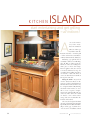
A
s we took an inventory of the “musthaves”for our kitchen
island, we didn’t get
any further than the
first item on the list — an indoor grill
— before we knew for certain that no
ordinary island would do (Photo, left).
Mounting a gas grill in what is
essentially a cabinet is no small thing,
after all. But we didn’t want the
island to be reduced to nothing more
than a place to house this unique
kitchen appliance. We also wanted
to include additional storage for
everything from grilling utensils to
our favorite cookbooks. And, of
course, the island had to look like it
belonged in a kitchen.
Fitting the Grill — As you look
over the Construction Details on the
next page, you’ll see that this kitchen
island is a bit unorthodox in the way
it’s compartmentalized. By dividing
the island in this manner, we were
able to create a separate compartment for the grill and still make use
of the rest of the cabinet for a bank
of drawers, some undercounter
storage, and even a bookshelf on the
backside of the island.
Of course, the design of the island
depends on using this particular grill.
Specifically this model from ProFire
(Buyer’s Guide, page 57) allows for a
“zero-clearance” installation, which
46
WO R K B E N C H
■ OCTOBER
2005
ProFire Indoor Gas Grill
(Model PFINDOOR)
designed to fit a
zero-clearance opening
(see Buyer’s Guide on page 57)
Custom Countertop
made with plastic laminate
over a double layer of MDF
(see page 58)
Case
is designed
with a large
opening to
accommodate
grill
Trim Strip
adds a linear
horizontal
design element
The ProFire Indoor
Gas Grill we used
requires a range
hood with a 1500
cfm blower.
34!/2"
We installed a
Broan-NuTone
Range Hood (model
#630004EX) with a
Rangemaster 1500
cfm exterior blower
(see Buyer’s Guide
on page 57)
Drawers
assembled with strong
half-blind dovetail
joints (see page 55)
Brushed Nickel Pulls
add a contemporary
look and a nice
contrast with the
oak cabinet
Full-Extension Slides
allow easy access to
back of drawer
Solid-Wood Frame &
Plywood Panel Doors
constructed with
mortise & tenon joints
(see page 54)
Construction Details
Overall Dimensions: 431/8" W X 481/8" D X 36" H
means we didn’t need to be concerned with how close the case parts
are to the grill. That allowed us to
really maximize the space.
Furniture Styling — Technical
issues aside, another priority for this
island was to create a furniture-like
appearance that could be carried to
the other kitchen cabinets. To that
end, we treated the island to a set of
Craftsman-inspired legs that would
look just as good on a living room
piece as they do here (Photo, right).
The island is further embellished
with frame-and-panel end assemblies and applied molding. The cabinet doors are built using genuine
mortise-and-tenon joinery and are
adorned with wood pegs. And, of
course, the drawers are dovetailed
W W W. W O R K B E N C H M A G A Z I N E
Ventilation
Notes:
Decorative
Pegs
give the
appearance
of pinned
tenons
4-Piece Legs
with Craftsman-style
details are built using
simple table saw and
router techniques
(see page 50)
together, so they’re on par with all
the other fine details of the island.
Wood selection was another
important choice. We carefully
selected quartersawn red oak for the
solid-wood pieces and looked for
the straightest grain we could find
when shopping for plywood.
Naturally, not just any countertop
would do. So we built our own.We
used time-tested plastic laminate over
an MDF substrate to create the perfect countertop for this island.
Over the next few pages, we’ll
walk you through the construction
of this kitchen showpiece. From the
basic case, to the decorative legs, and
all the way through the custom
countertop, the step-by-step instructions begin on the next page.
.COM
End Assembly
features unique frame-andpanel construction that
contributes to the island’s
furniture-style appearance
(see page 53)
} Simple table saw and router techniques make the shallow square
recesses, decorative groove, and
wrap-around trim easy to create.
“nearly standard” case
CONSTRUCTION
Beneath the decorative legs, applied
molding, and frame-and-panel end
assemblies,this kitchen island is a nearly
standard plywood case (Case Assembly).
I say nearly standard because there are
a few unusual details.We’ll come to
those soon enough, but first let’s look
at the the basic case.
The case consists of a bottom (A),
two sides (B,C), a back (D), a vertical
divider (E), and a fixed shelf (F).All
of these parts are cut from 3/4" plywood and joined with dadoes,
rabbets, grooves, and woodscrews.
The plywood edges get covered
with solid-wood edging, and that’s
when those unusual details I mentioned start showing up.
Case Panels —– To get started,
cut the panels (A through F) to size.
Now cut a notch on the top corner
of the vertical divider (Notch Detail,
page 49).This notch will accept a stiffener a little later. Simply lay out the
notch, and cut it with a handsaw.
The next step is cutting the joinery,
and this is where you find the first of
those unusual details.
Notice that the case sides have different letter designations (B,C) even
K
CASE ASSEMBLY
Stiffeners
(#/4" x 3" x 39")
D
Back
(#/4" ply. x 30"
x 39!/2")
F
G
Fixed Shelf
(#/4" ply. x 22#/4"
x 28&/8")
C
Fixed Shelf
Edging
(#/4" x #/4"
x 28&/8")
E
Left Side
(#/4" ply. x 34"
x 30!/2")
Vertical
Divider
(#/4" ply. x 23!/2"
x 30")
B
A
Bottom
(#/4" ply. x 34" x 39!/2")
NOTE: Cut all
dadoes, rabbets,
and grooves
!/4" deep, width to fit
#/4" plywood
Right Side
(#/4" ply. x 34"
x 30!/2")
Groove
for back
H
Front Bottom Edging
(#/4" x 2!/4" x 39")
J
though they have identical dimensions.What differentiates these parts is
the joinery.The right side panel (B)
has a dado for the fixed shelf, and the
left side (C) does not. It’s an important detail that’s easy to overlook.
With that in mind, you can get
started making the joinery.The size
of the plywood panels, and the fact
that some of these joints are
“stopped,” pretty much dictates that
you use a handheld router and a
straight bit to make the joints. Clamp
a straightedge to the workpiece to
guide the base of the router, and use
some wood scraps as stop blocks
when routing the stopped dadoes.
Hardwood Edging — With the
panels cut to size and the joinery
completed, you’re ready to add hardwood edging. And once again we
encounter some of those “details.”
The four pieces we’re dealing with
here are the fixed shelf edging (G),the
front and back bottom edging (H, I),
and the vertical divider edging ( J).Of
these, only the fixed shelf edging is
what you might think of as typical.It’s
cut to match the shelf in both thickness and width and then applied with
glue and clamps.
10!/8"
#/4"
Stopped dado
for divider
A
#/4"
Vertical Divider Edging
(#/4" x 2!/4" x 29")
34"
23!/4"
PARTS VIEWS
Grooves for back
23!/4"
30!/2"
!/4" holes,
!/2" deep,
for shelf pins
#/4"
C
#/4"
1!/2"
See Notch
Detail, next page
30"
18!/2"
8!/2" 12"
#/4"
Dado for divider
10!/8"
1"
Rabbets for bottom
34"
48
Stopped dado
for fixed shelf
B
34"
#/4"
Dado
for fixed
shelf
18#/4"
#/4"
Stopped groove
for fixed shelf
30"
D
E
23!/2"
39!/2"
WO R K B E N C H
■ OCTOBER
2005
E
Vertical
Divider
ASSEMBLING THE CASE
The bottom edging pieces are a
little more involved. First of all,notice
in the Edging Detail, right, that these
pieces stop 1/4" shy of the panel edge.
This is because of the way the legs
interlock with this panel. A second
important point is that these edging
pieces are not the same thickness.The
edging on the back edge of the panel
is thicker so it will match an adjustable
shelf that you’ll make later on.
The final detail to be aware of
with these edging pieces is a pocket
hole that must be drilled in each end.
This will be used to attach the legs
when the time comes.
As for the vertical divider edging,
what makes this part unusual is a
notch in the upper front corner
(Notch Detail). This accommodates
an apron that gets attached later.
Assemble the Case — The
Illustrations at right should make the
assembly sequence clear.But there are
a couple of points to take note of.
First, the vertical divider edging
presents a bit of a clamping challenge.
Fortunately, we worked out a simple
tip for applying this piece (page 22).
Next are the hardwood stiffeners
(K).These need to be pre-drilled with
two pocket holes (Stiffener Detail,
below).One hole is used to connect the
stiffener to the case.The other helps
secure the legs to the assembly later.
Then there’s a 1/4" plywood finish
panel (L) that’s glued to the back of
the case.This panel not only hides the
screws in the back, it also let us select
an attractive grain pattern for this
highly visible area of the island.
However, clamping this panel would
be tricky at best, so we used construction adhesive to create a strong
bond. There are some helpful tips
for this process on page 22.
The final piece of the case is an
adjustable shelf (M).The shelf is 1"
thick, so it can support heavy appliances or books without sagging.
Simply cut the shelf to size from
solid wood, and set it aside for now.
W W W. W O R K B E N C H M A G A Z I N E
STEP 1: Apply hardwood
edging to fixed shelf
and bottom panel
(see Edging Detail)
Edging Detail
Pocket Hole
(drilled from
underneath)
!/4"
F
Fixed Shelf
I
A
G
B
I
Right Side
Back Bottom Edging
(1" x 2!/4" x 39")
Front Bottom Edging
(#/4" x 2!/4" x 39")
A
H
Bottom
H
STEP 2: Assemble
bottom, right side, fixed shelf,
& vertical divider
with glue & screws
#8 x 1!/4"
Fh Woodscrew
STEP 3: Attach back
& left side with
glue & screws
Notch Detail
D
Back
J
C
#/4"
Vertical
Edging
Left Side
1!/2"
F
E
Vertical
Divider
6"
E
#/4"
B
A
J
Vertical
Divider
Edging
STEP 4: Glue edging to
vertical divider (see page 22
for clamping technique)
STEP 5: Attach the
hardwood stiffeners
with 1!/4"pocket screws
K
Stiffeners
Stiffener Detail
1!/2"
Pocket
Hole
1!/4" Pocket
Hole Screw
STEP 6: Glue
on Finish
Panel
E
B
D
K
Drill #/16"
pilot holes
for attaching
countertop
.COM
#8 x 1!/4"
Fh Woodscrew
C
L
Finish Panel
(!/4" plywood,
29!/2" x 39")
A
STEP 7: Make
adjustable shelf
and set aside
M
Adjustable Shelf
(1!/16" x 9#/4" x 38&/8")
NOTE:
Back view of
case shown
49
Craftsman-inspired legs in
FOUR EASY PIECES
The Craftsman-inspired, furniturestyle legs are clearly the most striking
feature of this kitchen island. That’s
due to the square recesses and long,
decorative groove that adorn one face
of each leg.
But just as interesting as the look
of these details is the technique used
to create them. They’re not handcut, as it may appear, but rather made
using a combination of table saw
and router table techniques.
That’s possible because each leg is
actually made from four boards,rather
than a single, thick blank. By ripping
one of these boards into thin strips,it’s
simple to cut or rout the decorative
details.Then the strips get glued back
together to create the finished face.
But that’s only one reason to build
legs in this manner. It also creates a
LEG ASSEMBLY
3"
3"
45°
bevels
N
NOTE:
Finished
leg is 3"
square by
34!/2" long
Decorative Leg Face
(#/4" x 3" x 34!/2")
!/2"-square
recesses
!/4" deep
O
Plain Leg
Face
(#/4" x 3"
x 34!/2")
!/4"-wide
groove,
!/4" deep
#/4" dado,
!/4" deep
(cut around
all four
sides of leg)
50
much more stable leg than a single,
thick board would — provided you
could even find stock large enough to
make these legs.And in the end, you
actually wind up using less material
this way than if you tried to work
with a solid piece of hardwood.
So now that we know the advantages of four-piece legs, let’s get
started making them. Just to clarify,
each of the four legs is made up of
one decorative face (N) and three
plain faces (O) (see Leg Assembly,
below).The decorative faces are where
we are going to get started.
Decorative Faces — As I mentioned, each decorative face will be
ripped into strips (five to be exact), so
we can cut and rout the decorative
elements in those individual strips.
That means we need to account
for the waste that’s lost when we rip
each blank apart. So to get started,
you’ll need four face blanks that are
31/2"-wide.These should also be extra
long (36" or so).They’ll be cut to finished length after the leg is assembled.
When you have the four blanks
ready to go, you need to mark them
in such a way that you’ll easily be
able to reassemble the strips correctly.
If the strips get mixed up during this
process,you could wind up with mismatched grain. An easy way to prevent that is to mark one end of each
blank with a different color of marker.
Now you’re ready to rip the
blanks into strips (Illustrations, page
51).This requires a couple different
table saw setups. First, position the
rip fence 7/8" from the blade.Cut
the first strip from the blank, then
turn the board end for end, and rip
a strip from the opposite edge.
Repeat this process for each blank.
Now, reposition the fence to cut
a 1/2"-wide strip, and use the same
process as before to cut the two inner
strips. The final cut you make also
forms the 1/4"-wide center strip.
Take a moment now and make
sure all the strips are grouped with
their matching parts before moving
on to the next step.
Dadoing the Details — The four
square recesses that adorn the leg faces
are created by cutting dadoes in the
1/ "-wide inner strips. Use a miter
2
ASSEMBLING THE FOUR-PIECE LEGS
The four-piece legs are assembled
with miter joints to prevent the edge
grain from showing. It’s important
when assembling the legs that all four
5#/4" faces are the same width. Ideally, the
decorative faces you’ve already
made are 3" wide. If not, simply rip
the three plain faces to match.
Once you’ve ensured that all the
leg faces are the same width, the
next step is to rip a bevel on both
edges of each face in preparation
for assembly.
Start by tilting the saw blade to
45°. Then position the fence so you’re
just cutting away a wedge from the
#/4" edge of the board without making
the face any narrower (Fig. 1). You
may want to perfect this setup on a
scrap piece before moving on to the
actual leg parts.
To assemble the legs, lay the faces
flat on pieces of tape. Spread glue
on the mating edges. Then “roll” the
leg faces together into a single post,
and secure them with the tape (Fig. 2).
After the glue dries, the next step
is to trim the legs to length (341/2").
Measure down from the top of the
leg to establish the cut line, then trim
them, as shown in Figure 3.
Finally, mount a dado blade in your
table saw to make the final cut in the
legs. This dado will accept a trim strip
that gets attached later in the island
construction. Cut the dado all the way
around the leg using the rip fence as
a stop block (Fig. 4).
WO R K B E N C H
■ OCTOBER
2005
MAKING DECORATIVE
LEG FACES
NOTE:
STEP 1: Rip each
Each decorative leg
face starts as a
#/4"x 3!/2"x 36"
blank
decorative face
into five strips
gauge and stop block to ensure consistent results when making these cuts.
Routing the Groove — Next
comes the decorative groove. It’s
formed by cutting a long notch in
the center strip. Most of this material will be removed on the router
table, but it’s best to first establish
the shoulders of the notch on the
table saw (Fig. 1). Once that’s done,
remove the stop block and make
several more passes to widen the cuts
to about 1/2".This will make it easier
to start the cut on the router table.
To do that, mount a straight bit
in the router table.Then tape the strip
to a sacrificial backer board for support and to give yourself a safe handhold (Fig. 2). Now make a sideways
plunge cut into the bit to remove the
remaining waste material (Fig. 3).
Reassembling the Face —
Now reassemble the strips into a
single face. First, ensure that the strips
are back in their original group.Then
spread glue on the mating edges and
align the recesses as you clamp the
assembly. After the glue dries,
assemble each leg, as shown below.
1
Auxiliary Face
3!/4"
Miter
Gauge
STEP 3:
&/8"
STEP 2:
!/2"
!/4"
!/2"
&/8"
!/4"
!/2"
Cut !/2" dadoes
!/4"-deep to
create square
recesses
Form the groove
by cutting a notch
in the center strip
(see art, right)
Carefully align the
recesses and the top
ends of the strips as
you glue the decorative
face back together.
2
3
4
.COM
Center
Strip
Double-Sided
Tape
Sacrificial
Backer
Board
2"
STEP 4:
Stop
Block
2
!/2"
1
W W W. W O R K B E N C H M A G A Z I N E
CUTTING THE GROOVE
3#/4"
3
Router
Table
Fence
Center
Strip
Center
Strip
Sacrificial
Backer
Board
!/2"
Straight
Bit
51
END ASSEMBLY VIEW
Stub Tenon Detail
Stop Detail
Leg Mount Detail
frame & panel
END ASSEMBLIES
The frame-and-panel end assemblies are
just as important to the furniture-like
appearance of this island as the legs are.
And, just like the legs, they feature some
unusual construction.
The frames themselves are fairly standard
— they’re solid-wood pieces that are assembled with stub-tenon-and-groove joinery
(End Assembly View, above). What makes
these assemblies unique is that the groove
doesn’t house the panel, as you might
expect. Rather, it accepts a panel stop,
which in turn holds the panel.This simple
design twist adds one more layer of detail,
or depth, to the assembly to make it look
more like fine furniture and less like another
ordinary cabinet.
Frame First — To get started on the
assembly, cut the stiles (P), inner stile (Q),
and rails (R,S) from 3/4"-thick hardwood.
Next, cut a groove in the inside edge
of each of the frame pieces (in both edges
of the center stile) to accept the panel stop
52
that will support the 1/4" plywood panels.
Then, cut stub tenons on the ends of the
rails and the center stile to fit into these
grooves (Stub Tenon Detail, above).
Now it’s time to assemble the frame.
Be sure to make alignment marks to position the center stile as you glue and clamp
the frame together.
Panel Stops — With the frames assembled, you’re ready to add the panel stops
(T). Besides providing a way to attach the
panels, the stops serve another purpose.
Notice how they add extra depth and
dimension to the end assemblies in the
Photo on page 46.To make the stops, plane
some stock to thickness to fit snugly into
the grooves.Then rip the stops to width,
cut them to length, and glue them into
the grooves (Stop Detail).
End Panels — Next, measure the
opening in the frame, and cut the plywood
end panels (U) to fit. Before gluing the
panels into the frames, take a minute to
mask the panel with tape, so any excess
glue winds up on the tape (Photo, right). By
the way, be sure you’re masking the good,
or “show,” face of the panel — 1/4" plywood
only has one such face.
Ledge and Apron — Now it’s time to
add a decorative ledge (V) and end apron
(W) to the assembly. Cut these pieces to size
from 3/4"-thick hardwood and then drill
pocket holes in them as shown in the
Assembly View.These pocket holes will be
used to join the end assembly to the legs.
Once these holes are drilled, glue the ledge
and apron to the frame-and-panel assembly.
Assembly — Connecting the completed assemblies and legs can be challenging because you have to manage fairly
large units and keep them aligned. And
speaking of alignment, note how the end
assemblies are set back 3/4" from the face
of the leg (Leg Mount Detail). This is yet
another detail that helps create a furniturestyle look.
WO R K B E N C H
■ OCTOBER
2005
To assemble these pieces, start by placing the
legs (outside face down) on a large, flat surface.
Then position the end assembly (also face
down) between the legs. Support the assembly
with some 3/4" scrap pieces.This will give you
the perfect setback from the face of the legs to
the face of the end assembly.
Align the parts so the tops of the legs are
flush with the top of the end assembly. Install
the pocket screws to secure the whole works.
Add the Spacers — Before the end assemblies are ready to be attached to the case, you
need to add a couple spacers (X).As the name
implies, they “fill” the space between the end
assemblies and the case, and also create a large
glue surface for attaching the end assemblies
to the case (Spacer Detail). Cut these pieces to
fit between the legs, and glue and screw them
to the end assemblies.
Now you can attach the end assemblies to
the case.You’ll need to “jack up” the case, so
it’s flush at the top with the end assemblies.
Installation Detail
Spread glue on the spacers, and then clamp
them to the end assemblies. Next, drive pocket
screws from the stiffeners and into the end
assemblies (Installation Detail).
Applied Details — There are just a few
details left to complete the case. First is a hinge
jamb (Y).This piece ensures the proper clearance between the door and side of the case, so
the hinges will be able to swing fully open.
Notice that this piece has a notch cut in it to
go around the fixed shelf (see the Hinge Jamb
Detail, below).
Next are the front and back apron
pieces (Z, AA).These are simply cut
to fit, and then they are pocketscrewed to the case sides.
Finally,add the decorative trim strips
(BB, CC) that wrap around the case.
First, cut a notch in both ends of each
trim strip to fit into the dadoes in the
legs.Then miter the pieces to length,
and glue and clamp them in place.
< To protect the
panel from glue
squeeze-out, run
masking tape
1/ " in from the
4
edges of the
panel before
gluing it in place.
END PANEL & TRIM ASSEMBLY
CC
End Trim Strip
(#/4" x 1"
x 40!/2")
Pocket Hole
& 1!/4" Pocket
Hole Screw
AA
Back Apron
(#/4" x 6#/4"
x 39")
K
Hinge Jamb Detail
Z
Front Apron
(#/4" x 6#/4"
x 29!/8")
X
BB
Upper
Spacer
Y
Front/Back
Trim Strip
(#/4" x 1"
x 45!/2")
Hinge Jamb
(#/4" x 3!/2" x 23")
#8 x 1!/4" Fh
Woodscrew
X
Trim Strip Detail
Spacer Detail (Front View)
Lower Spacer
(#/4" x 3" x 34")
NOTE: Use scrap pieces
to elevate case, so it’s
flush with top edge
of end assemblies
End Assembly
CC
TRIM STRIP PART VIEW
BB
CC
!/2"
3!/4"
!/2"
W W W. W O R K B E N C H M A G A Z I N E
.COM
53
assembling the
DOOR CONSTRUCTION
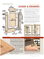
DOORS & DRAWERS
These doors share the frame-and-panel look of the end
assemblies and require some of the same techniques (Door
Construction). The difference in the doors, however, is
joinery. Here, the rails and stiles are joined with mortise-and-tenon joints for extra strength.
Door Frames — Get started building the doors by
cutting the rails (DD, EE) and stiles (FF) to size.
Now cut the tenons and mortises in these pieces.To
cut the mortises, either use a mortising machine, or drill
out the rough shape with a Forstner bit, and then chisel
them to final size (Mortise Detail).The tenons are easy to
make with a dado blade on the table saw (Tenon Detail).
Next, cut the groove in the frame pieces for the panel
stop.You’ll want to do this on the router table, so you can
stop the grooves in the mortises. Use stop blocks on the
router table fence to start and stop this cut.Then assemble
the door frames using glue and clamps.
Lower Tenon Detail
Lower Mortise Detail
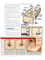
MAKING THE SQUARE PEGS
There was a time when wood pegs were used to
add even more strength to a mortise-and-tenon
joint. With today’s adhesives, that extra step isn’t
really necessary. Nonetheless, the pegs still make
a nice decorative element. But since they are only
decorative, there’s no need to extend the peg all
the way through the workpiece. Rather, by
drilling a shallow hole and then chiseling
it square, you can create a mortise
to accept a short peg that looks
like the real thing, but requires
a lot less work.
And by having the end grain
of the peg exposed, it will contrast with the frame pieces when you
apply a finish. The Photo sequence will walk you
through the rest of the process.
54
1
{ To add the decorative wood pegs, start by using
a 3/8" Forstner bit mounted in the drill press to drill
a 1/4"-deep hole in the door stile.
WO R K B E N C H
■ OCTOBER
2005
Panel Stops — The plywood panels in these doors,
just like the panels in the end assemblies, are held in the
frames with panel stops (GG). Just as before, plane these
to thickness and cut them to fit.Then glue and clamp
them into the grooves in the door frame.
Now measure the opening in each door, and cut a
plywood panel (HH) to size. Once again, use masking
tape to keep excess glue off the plywood panel.
Decorative Pegs — To add a bit more Craftsman
flavor, these doors are accented with decorative wood
pegs (II) at the corners. The four-step process for this
is shown in the Sidebar below.
Hardware — The completed doors are now ready
for hardware, which amounts to a couple of cup hinges
and a door pull. Drill and mount those pieces according
to the dimensions in the Door Construction Illustration
on page 54.
Dovetailed Drawers — Now you’re ready to build
the drawers (Drawer Construction Illustration). These are
standard dovetailed boxes with a false front.
Start by cutting the drawer fronts, backs (JJ, KK),
and sides (LL, MM) to size.Then lay out the dovetails
according to the dimensions in the Dovetail Detail. Cut
the dovetails with a handheld router and a half-blind
dovetail jig. (For more information on routing halfblind dovetails, see the article in the Online Extras section at WorkbenchMagazine.com.)
After routing the dovetails, cut a groove in the drawer
box pieces to accept the plywood bottom. Now cut
the bottom (NN) to fit, and glue and clamp the drawer
box together.
Next, cut the false fronts (OO, PP) to size, and then
screw them to the boxes with the bottom edges flush.
Now drill each drawer for the pulls, and install the
hardware. Finally, install the drawer pulls, and mount the
drawers in the island with full-extension drawer glides.
2
Drawer Detail
7&/8"
LL
{ Now, cut with the grain to
square off the remaining edges of
the mortise. The intersecting
edges of the mortise have
already been established, so this
part of the cut will go smoothly.
.COM
Dovetail Detail
MM
3
{ Next, use a chisel, and cut
across the grain to establish the
first edge of the mortise. By cutting
across the grain first, you will
prevent the the wood from splitting during the next few cuts.
W W W. W O R K B E N C H M A G A Z I N E
DRAWER CONSTRUCTION
5!/4"
4
{ Finish up by gluing a 3/8" x 3/8" peg into the
mortise. Leave the peg slightly proud, and then
sand it flush with the surface after the glue dries.
55
island installation &
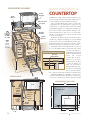
COUNTERTOP ASSEMBLY
ProFire
Gas Grill
Plastic
Laminate
QQ
Countertop
Substrate
(1!/2"MDF x
43" x 48")
Electrical
Outlets
NOTE:
Make
substrate
from two
pieces of
#/4" MDF
Flexible
Conduit
Shut-off
Valve
L-Bracket
Mounting
Box
Pipe
Union
SECTION VIEW
COUNTERTOP
Installing the nearly complete kitchen island is more
than just setting it in place.The island will also have to
be wired with electricity and plumbed with gas.
Grill Power Cord
The power line will feed two outlets: one inside the
(for igniter)
compartment for the grill igniter to plug into and
another that’s accessible from the outside of the island
for plugging in appliances (see Illustrations at left).The gas
line needs to include a shut-off valve inside the compartment.You’ll want to have easy access to this shutBlack Pipe
Coupling
off valve, so it’s important to keep the gas line toward
the front of the island.
Flexible
Both lines should be fed from underneath the floor
Gas Line
and into the compartment through access holes drilled
in the bottom of the case.This will leave the lines partially exposed where they span between the floor and the
bottom of the island, so you’ll need to protect them.
A simple box with one removable side (in case you need
to access the utilities) will serve nicely. The box consists
of four boards ripped to
width from 2x6 stock to fit
Countertop Mounting Detail
under the island and then
#8 x 1#/4"
butted and screwed
Fh Woodscrew
together. Use metal Lbrackets to secure three
Rigid
Countertop
Black
sides of the box to the floor.
Pipe
Once the utilities are
K
taken
care of and you’ve
W
moved the island into position, drive screws through
the case bottom and into
three of the box sides (but not into the removable side).
Custom Countertop — Building a custom countertop for this island was an absolute necessity.There’s
no way we could find a pre-made version that would
COUNTERTOP (TOP VIEW)
48"
Grill
Electrical
outlet for
kitchen
appliances
Island location
Flexible
Gas Line
Grill Power
Cord
Electrical
outlet
for grill
43"
Grill Opening
Shut-off
Valve
Flexible
Conduit
6"
Pipe Union
Height Cut
to Fit
56
Supply Line
19#/8"
Gas Supply
28#/8"
WO R K B E N C H
■ OCTOBER
4!/2"
2005
KITCHEN BUYER'S GUIDE
ProFire Indoor Grill
Drawer/Door Pulls
Drawer Slides
Faucet/Sink
Dvorson’s Food Service
Smedbo Cabinet Hardware
Blum
Kohler
877-386-7766
Dvorsons.com
866-695-6627
MyKnobs.com
800-857-8721
CabinetParts.com
800-456-4537
Kohler.com
Range Hood
Cup Hinges
Plastic Laminate
Countertop
Broan NuTone
Blum
Formica
John Boos
800-558-1711
Broan.com
866-344-6437
BlumHinges.com
800-367-6422
Formica.com
217-347-7701
JohnBoos.com
be large enough or provide the perfect
complement to the look of the island.
The easy choice was to fabricate our own
countertop using an MDF substrate and
plastic laminate (Countertop Assembly). The
technique couldn’t be much easier. One
unexpected bonus is how affordable this
material turned out to be compared to other
popular countertop materials (about $5 a
square foot for laminate versus as much as $90
a square foot for solid-surface material).
The fundamentals of building your own
laminate countertop, and then cutting an
opening for a sink, or in this case, a grill, are
covered in the article on page 58.
There is one important detail in this version that differs just slightly, however.
In this case, the substrate is made of two
full layers of MDF instead of one full layer
on top and a series of cleats underneath.We
wanted the extra strength that comes from
two full layers of substrate to help support
the weight of the grill.
Attaching the Countertop — After
you’ve cut the opening for the grill, it’s
time to attach the countertop to the island.
Position it on the island, and then check to
ensure that it’s sitting square and centered.
Once you’re satisfied with the position of
the countertop, I recommend clamping it
temporarily, so it doesn’t shift while you’re
attaching it permanently.
As for attaching the countertop, you
predrilled holes in the stiffeners as you
were building the case, so you can simply
drive woodscrews at those locations to
secure the top.
All that’s left is to install the grill. And
the instructions that came with it are the
best source as to how that’s done.
That completes your dream island and
part one of this kitchen remodel.In the next
issue, we’ll detail the matching cabinets, an
undermount sink, and butcher block countertops to complete the makeover.
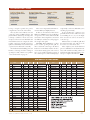
MATERIALS & HARDWARE
Part
A
B
C
D
E
F
G
H
I
J
K
L
M
N
O
P
Q
R
S
T
U
V
W
X
Y
Z
Case Bottom
Right Side
Left Side
Back Panel
Vertical Divider
Fixed Shelf
Fixed Shelf Edging
Front Bottom Edging
Back Bottom Edging
Vertical Divider Edging
Stiffeners
Finish Panel
Adjustable Shelf
Decorative Leg Faces
Plain Leg Faces
Stiles
Inner Stiles
Upper Rails
Lower Rails
Panel Stops
End Panels
Ledges
End Aprons
Spacers
Hinge Jamb
Front Apron
Qty
T
W
L
1
1
1
1
1
1
1
1
#/4"
#/4"
#/4"
#/4"
#/4"
#/4"
#/4"
#/4"
34"
34"
34"
30"
23!/2"
22#/4"
39!/2"
Oak Plywood
1
1
2
1"
#/4"
2!/4"
2!/4"
3"
30!/2"
30!/2"
39!/2"
30"
28&/8"
28&/8"
39"
39"
Oak Plywood
Oak Plywood
Oak Plywood
Oak Plywood
Oak Plywood
Oak
Oak
Oak
29!/2"
29"
39"
39"
Oak
Oak
Oak Plywood
#/4"
#/4"
9#/4"
3"
3"
38&/8"
34!/2"
34!/2"
2!/2"
3"
2!/2"
23"
2
2
#/4"
#/4"
#/4"
Oak
Oak
2
16
4
#/4"
!/4"
!/4"
4"
!/2"
13"
17"
29!/2"
29!/2"
Oak
Oak
Oak
2
2
4
#/4"
#/4"
#/4"
1!/4"
6#/4"
to fit
16!/2"
34"
Oak
Oak Plywood
Oak
1
1
#/4"
#/4"
1
1
4
12
4
#/4"
!/4"
1"
W W W. W O R K B E N C H M A G A Z I N E
#/4"
2!/4"
3"
3!/2"
34"
34"
23"
6#/4"
29!/8"
.COM
Material
Oak
Oak
Part
AA
BB
CC
DD
EE
FF
GG
HH
II
Back Apron
Trim Strips (Front/Back)
Trim Strips (End)
Top Door Rails
Bottom Door Rails
Door Stiles
Panel Stops
Door Panels
Qty
T
W
L
1
2
2
2
2
4
8
#/4"
#/4"
#/4"
#/4"
#/4"
#/4"
!/4"
!/4"
#/8"
6#/4"
1"
1"
2!/2"
4"
2!/2"
!/2"
8%/8"
#/8"
39"
45!/2"
40!/2"
11!/8"
11!/8"
22#/4"
to fit
!/2"
!/2"
!/2"
2
Wood Pegs
8
JJ Shallow Drawer Fr./Bk. 4
4
KK Deep Drawer Fr./Bk.
4
LL Shallow Drawer Sides
4
MM Deep Drawer Sides
NN Drawer Bottoms
OO Shallow Drawer False Fronts
PP Deep Drawer False Fronts
QQ Countertop Substrate
!/2"
4
!/4"
2
2
2
#/4"
#/4"
#/4"
Material
16!/4"
Oak
Oak
Oak
Oak
Oak
Oak
Oak
Oak Plywood
5!/4"
7&/8"
!/4"
8&/8"
8&/8"
Oak
Oak
Oak
5!/4"
7&/8"
22%/8"
22%/8"
Oak
Oak
8#/8"
5#/4"
8#/8"
22!/2" Oak Plywood
9%/8" Oak
9%/8" Oak
48" MDF
43"
Oak
Oak
Oak
Oak
57