1
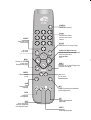
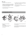
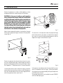
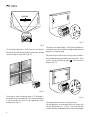
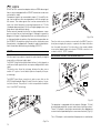
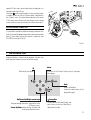
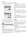
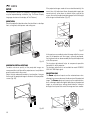
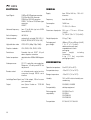
cod.46.0338.200
Installation manual
STAND-BY
Switches off to stand-by.
0-9 Keys
SOURCE
Displays the Source
Selection menu.
Switch on from stand-by
and allow direct source
selection.
ESCAPE
Deactivates the On Screen Display.
Not active
in this model.
Up/Down/Left/Right Arrow keys
Navigate through and make adjustments
to the On Screen menus.
Arrow Up/Down
menus.
MENU Activates the On Screen
Display menus.
Navigates menu pages.
FREEZE
Freezes a moving
picture.
ZOOM
Selects lens zoom
adjustment.
MENU +
Activates the On Screen Display menus.
Navigates menu pages.
Not active
in this model.
INFO
Displays the selected source information
and the projector status.
FOCUS
Selects focus
lens adjustment.
AUTO
Selects Auto Adjust
(automatic optimisation
of the displayed image).
VCR
Improves the video recorder
signals quality.
ASPECT
Selects image Aspect ratio.
1 INTRODUCTION
Congratulations and thank you for choosing a DOMINO-H
projector, a SIM2 Multimedia SpA product (Fig. 1).
ttre
comprome
d'incende
ne pas
type
N: pour les resque
de meme
ATTENTIO contre
fusible
ique
par un
against
la protection
caracterist protection
remplacer
mems
et de
: for continued
CAUTION
fire, replace
type
risk of same
with fuse.
only
and rating
R/Cr
L
ICS
ZOOM
RGB
G/Y
3
4 GRAPH
5 DIGITA
AUDIO
OUT
INPUT
B/Cb
2
1
OL (RS
232)
CONTR
HV
1
A sophisticated proprietary optical system, coupled with a hight
performance zoom lens ensures hight contrast images, superior
uniformity and edge-to-edge definition.
A new 6-segment colour wheel dramatically reduces the so
called “rainbow effect” and gives a better contrast, better
colorimetry and a lower black level to the image.
The DMD™ chip resolution identifies the DOMINO-H projector:
1024x576 pixel for DOMINO 20-H model and 1280x720 pixel
for DOMINO 30-H model. For both models the high contrast
ratio deliver on the screen an even more realistic image.
Fig. 1
Using the very latest in DLP™ technology, this projector has
been designed specifically for high quality “Home Cinema”
applications.
The renowned DCDi™ technology is adopted for deinterlacing:
conversion from interlaced to progressive produces a smooth
and natural image, without flickering, loss of vertical resolution
and jaggedness along diagonal lines.
The low-noise ventilation system – with variable speed fans –
ensures appropriate cooling and maximizes projector reliability.
Sophisticated digital processing and a wide choice of inputs
enable the connection of a variety of sources such as DVD
players, analogue and digital VCRs, analogue and digital satellite receivers and personal computers etc.
To fully appreciate your new projector we recommend the use
of a good quality screen and surround-sound system. Contact
your nearest authorized SIM2 Multimedia dealer for further
details.
The long throw zoom lens allows the position of the projector to
be located behind the viewer, thus reproducing a cinema-like
installation (Fig. 2).
SIM2 carries out comprehensive functional testing
in order to guarantee the maximum product quality.
For this reason, when you start using the product
lamp operating hours may already be at between
30 and 60.
In addition to the regular tests, the Quality Control
department performs additional statistical tests at
the time of shipment.
In this case the packing may show signs of having
been opened, and the accumulated lamp operating
hours may be slightly higher than the hours associated with the standard tests.
C-SYNC
Fig. 2
2
DLP and DMD are registered trademarks of Texas Instruments.
DCDi is a registered trademark of Faroudja, a division of Genesis
Microchip, Inc.
HDMI, the HDMI logo and High-Definition Multimedia Interface are
trademarks or registered trademarks of HDMI Licensing LLC.
3
2
1
5
8
7
4
6
1
2
3
4
5
6
7
8
Projection lens
Lens shift knob
Cooling air inlet vents
Remote control IR sensor
Cooling air outlet vents
Adjustable carry-handle
Adjustable levelling feet
Ceiling/wall bracket fixing holes
9
10
11
12
13
14
15
16
17
18
19
20
21
22
Fused power socket
Main power switch
Remote control rear IR sensor
Green LED
Red LED
Rear keyboard pad
Composite video input
S-Video input
VGA input
RGB / YCrCb input
HDMI™ input
Optical Audio Output
12Vdc screen output
RS232 interface connector
12 11 13 17
R/C
14
ZOO
M
RAP
4 G
H
R
ICS
GB
15
1
CON
TR
S
OL (R
r
I
G/Y
B/C
2
10
ettre
mprom e
pas co e d'incend
e
qu
ur ne
N: po e les res meme typ
NTIO
ntr
ATTE tection co fusible de
e
ainst
la pro cer par un teristiqu
tion ag
rac
remplamems ca
protec
ed
ntinu
et de
for co
ION: lace
UT
CA fire, rep type
risk of h same
wit
only ing fuse.
and rat
3
DM
5 H
9
IO
AUD
OUT
b
232)
HV
22
16
18
19
20
21
3
2 IMPORTANT SAFETY INSTRUCTIONS
ATTENTION:
To reduce the risk of electric shock, disconnect the
power supply cable on the rear panel before removing
the top cover of the projector.
Refer to trained, authorised personnel for technical
assistance.
This symbol indicates the possible electric shock
hazard associated with uninsulated live
components in the interior of the unit.
This symbol indicates the presence of important
instructions regarding use and maintenance of
the product.
Prior to switching on the projector please read each chapter of this manual carefully as this manual provides basic
instructions for using the projector.
The installation of the lamp assembly, preliminary adjustments and procedures that necessitate the removal of the
top cover, must be carried out by authorised, trained technicians. There are no user serviceable parts inside. To
ensure safe and long term reliability please use power cables supplied with the projector. Observe all warnings and
cautions.
• Federal Communication Commission (FCC Statement)
This equipment has been tested and found to comply with the limits for a Class B digital device, pursuant to Part 15 of the FCC rules. These limits
are designed to provide reasonable protection against harmful interference when the equipment is used in a commercial environment. This
equipment generates, uses and can radiate radio frequency energy and, if not installed and used in accordance with the instruction manual, may
cause harmful interference to radio communications. However, there is no guarantee that interference will not occur in a particular installation. If
this equipment does cause harmful interference to radio or television reception, which can be determinated by turning the equipment off and on,
the user is encuraged to try to correct the interference by one or more of the following measures:
- Reorient or relocate the receiving antenna
- Increase the separation between the equipment and receiver.
- Connect the equipment into an outlet on a circuit different from that to which the receiver is connected.
- Consult the dealer or an experienced radio/TV technician for help.
• For customers in Canada
This Class B digital apparatus complies with Canadian ICES-003.
• For customers in the United Kingdom
ATTENTION: This apparatus must be earthed
The wires in this mains lead are coloured in accordance with the following code:
Green-and-Yellow:
Earth
Blue:
Neutral
Brown:
Live
As the colours of the wires in the mains lead of this apparatus may not correspond with the coloured markings identifying the terminals in your plug
proceed as follows:
The wire which is coloured green-and-yellow must be connected to the terminal in the plug which is marked by the letter E or by the safety earth
symbol
or coloured green or green-and-yellow.
The wire which is coloured blue must be connected to the terminal which is marked with the letter N or coloured black.
The wire which is coloured brown must be connected to the terminal which is marked with the letter L or coloured red.
4
Please follow carefully the warnings listed below, to ensure safe
and long term performance of your projector.
• Connect the projector to a power supply with a nominal
voltage within the following values: 100-240 Vac, 50/60 Hz,
earthed (Fig. 3).
ettre
mprom e
pas coue d'incend
resq eme type
m
e de
nst
tique
n agai
otectio
ed pr
4
250 V
T 3.15A H
1
IO
AUD
OUT
3
mettre
compro cende
d'in e
r ne pas
: pou les resque me typ
me
tre
NTION
ATTE tection con fusible de
e
inst
la pro cer par un eristiqu
tion aga
act
remplamems car
protec
tinued
et de
for con
ION: lace
UT
CA fire, rep type
risk of h same
wit fuse.
y
onl ing
and rat
TAL
3
GI
5 DI T
2
O
AUDI
OUT
INPU
Fig. 4
100-240 Vac
• Do not obstruct the cooling air inlets on the top cover, or the
air outlets underneath the projector.
50/60 Hz
Fig. 3
• The mains plug is the disconnect device. Take care, when
installing, that the mains plug and socket outlet are easily
accessible. Never pull on the cable to take it out of the socket.
If the system is unlikely to be used for a number of days,
disconnect the power cable and other apparatus connected
to it.
• To save energy, switch off the projector by using the power
switch at the rear; when in stand-by (red light on) the
projector continues to draw a minimal amount of power.
• Only replace the safety fuse (on the power socket at the
rear of projector) with a fuse identical in type and
characteristics (T 3.15A H) (Fig. 4).
• Do not switch on your projector when flammable liquids or
fumes are present. Do not pour or drop fluids in the vents.
• Do not use the projector when the room temperature is above
35°C (95°F).
• Do not switch on the projector if it is standing on soft surfaces
such as cushions, pillows, blankets, mattresses and carpets:
the air cooling outlets underneath could become obstructed.
• Do not switch-on the projector if it is standing on surfaces
sensitive to heat, as this may result in damage caused by
the hot air outlets underneath. Should this be unavoidable
take extra precaution of protecting the surfaces with a layer
of heat resistant material.
• Intense Light Source! Do not stare directly into the projection
lens as possible eye damage could result. Be especially
careful that children do not stare directly into the beam.
• Do not open the projector’s cover; no user serviceable parts
are inside. Refer servicing to qualified service personnel.
Opening the projector’s cover will invalidate warranty.
• Take care not to shake the projector whilst carrying it by the
handle.
• Always position the projector away from direct heat sources.
5
• Do not touch the surface of the projection lens.
• The projector must be positioned on a stable, suitable
platform or be installed using a bracket for fixed ceiling or
wall installation. Do not rest the projector on the side panels
or on the rear panel when in operation.
• For installations using a ceiling or wall-mounted bracket,
carefully follow the installation and safety instructions
provided with the bracket’s literature.
• Please remove batteries from the remote control if not in use
for a long period of time.
• Take care to position cables safely, especially in dark places,
in order to avoid a trip hazard.
3 PACKAGING AND CONTENTS
Fig. 5
The carton should contain the following:
- the projector
- the remote control
- four 1.5V AAA batteries (for remote control)
- three power cables (EU, UK, USA)
- the user manual.
6
To unpack the projector safely and easily please follow steps 1
to 4, as drawing (Fig. 5).
It is recommended that the carton and packaging is retained
for future use and in the unlikely event that your projector needs
to be returned for repair.
4 INSTALLATION
Position the projector on a stable, suitable platform or utilise
the optional bracket for a fixed ceiling or wall installation.
CAUTION: In the case of ceiling or wall mounting
using a suspension bracket, follow the instructions
carefully and comply with the safety standards you
will find in the box together with the bracket. If you
use a bracket different to the one supplied by SIM2
Multimedia, you must make sure that the projector
is at least 65 mm (2-9/16 inch) from the ceiling and
that the bracket is not obstructing the air vents on
the lid and on the bottom of the projector.
FOCUS
FOCUS
FOCUS
FOCUS
compromettre
d'incende
ne pas
type
pour les resque
de meme
ATTENTION:contre
fusible
par un
against
la protection
caracteristique
remplacer
protection
mems
et de
for continued
CAUTION:
fire, replace
type
risk of same
with fuse.
only
and rating
R/Cr
S RGB
ZOOM
G/Y
3
4 GRAPHIC
5 DIGITAL
AUDIO
OUT
INPUT
B/Cb
2
1
(RS
232)
CONTROL
HV
Fig. 7
Adjust the feet underneath to obtain a level position, lining up
the base of the projected image to the base of the projection
screen (Fig. 6).
tre
compromet
d'incende
ne pas
type
: pour les resque
de meme
ATTENTION contre
fusible ue
par un
against
la protection
caracteristiq protection
remplacer
mems
et de
for continued
CAUTION:
fire, replace
type
risk of same
with fuse.
only
and rating
R/Cr
CS
ZOOM
RGB
The manual lens shift adjustment allows the projected image
to be moved vertically, up or down, in relation to the centre of
the screen; the maximum adjustment being equal to half the
height of the image in either direction (Fig. 8).
G/Y
3
4 GRAPHI
5 DIGITAL
AUDIO
OUT
INPUT
B/Cb
2
1
L (RS
232)
CONTRO
HV
compromettre
d'incende
ne pas
type
pour les resque
de meme
ATTENTION:contre
fusible
par un
against
la protection
caracteristique
remplacer
protection
mems
et de
for continued
CAUTION:
fire, replace
type
risk of same
with fuse.
only
and rating
R/Cr
RGB
ZOOM
G/Y
3
4 GRAPHICS
5 DIGITAL
AUDIO
OUT
INPUT
B/Cb
2
1
(RS
232)
CONTROL
HV
Fig. 6
Position the projector the desired distance from the screen:
the size of the projected image is determined by the distance
from the lens of the projector to the screen and the zoom setting.
See “Appendix C”: Projection distances” for more information.
Use the motorised lens zoom to adjust the image size and the
motorised lens focus to achieve maximum clarity. With optimum
focus you should be able to clearly see each single pixel when
within close proximity to the screen (Fig. 7).
Fig. 8
In the event you are unable to centre the image within the screen
area, tilt the projector until the image is correctly positioned.
Any keystone error can be removed by the Keystone adjustment
in the Set up menu (Fig. 9).
The kyestone adjustment is not available for model DOMINO
20 H with 1080i input signal.
7
KEYSTONE
20%
ettre
comprom
d'incende
ne pas
type
N: pour les resque
de meme
ATTENTIO contre
fusible
tique
par un
against
la protection
caracteris protection
remplacer
mems
et de
: for continued
CAUTION
fire, replace
type
risk of same
with fuse.
only
and rating
R/Cr
L
ICS
ZOOM
RGB
G/Y
3
4 GRAPH
5 DIGITA
AUDIO
OUT
INPUT
B/Cb
2
OL (RS
232)
CONTR
1
HV
C-SYNC
Fig. 11
Fig. 9
The Orientation adjustment in the Set up menu will allow the
projector to be used for desktop front, ceiling front, desktop
rear and ceiling rear installations (Fig. 10).
The output is activated (Voltage: 12 Vdc) when the projector is
switched on and is de-activated (no Voltage output) when the
projector is in stand-by mode.
Some manufacturers offer screen-masking systems to help frame the projected image and improve picture contrast. These
, at the rear of the
systems can be connected to output
projector (Fig. 12).
compromettre
d'incende
ne pas
type
pour les resque
de meme
ATTENTION:contre
fusible
par un
against
la protection
caracteristique
remplacer
protection
mems
et de
for continued
CAUTION:
fire, replace
type
risk of same
with fuse.
only
and rating
R/Cr
S RGB
ZOOM
G/Y
3
4 GRAPHIC
5 DIGITAL
AUDIO
OUT
INPUT
B/Cb
2
1
(RS
232)
CONTROL
ttre
comprome
d'incende
ne pas
type
N: pour les resque
de meme
ATTENTIO contre
fusible
tique
par un
against
la protection
caracteris protection
remplacer
mems
et de
: for continued
CAUTION
fire, replace
type
risk of same
with fuse.
only
and rating
HV
R/Cr
L
ICS
ZOOM
RGB
G/Y
3
4 GRAPH
5 DIGITA
AUDIO
OUT
INPUT
B/Cb
2
1
OL (RS
232)
CONTR
HV
Fig. 10
To activate an electric motorised screen a 12 Volt output is
provided at the rear of the projector. This can be connected to
a screen interface unit, which can be supplied by screen
manufacturers (Fig. 11).
8
Fig. 12
For rear projection the screen must be translucent.
For front projection, we recommend the use of screens with
low gain specifications (i.e. 1.3 to 2). The use of high gain
screens should be avoided due to their limited viewing angle,
which is undesirable for a large audience.
Preferably, use a screen with black, non-reflecting borders,
which will perfectly frame the projected image.
Avoid light shining directly on the screen during projection as
this will reduce contrast and black level detail on the projected
image. For the true cinema experience best results are
achieved with little or no ambient light.
Furniture and other objects with reflecting surfaces, as well as
light coloured walls should be avoided, as they are likely to
interfere with the screen’s characteristics.
5 SWITCHING ON AND OFF THE PROJECTOR
CAUTION: Connect the projector to a power supply
with a nominal voltage within the following values:
100-240 Vac, 50/60 Hz. It must be earthed (Fig. 13).
SWITCH ON FROM STAND-BY
By remote control: press one of 1...9
By keyboard: press Up or Down Arrow .
Position I : on
Position O : off
Power switch
Fused power
socket
ZOO
M
RA
4 G
2
Power plug
1
CON
TRO
PH
L (R
Fig. 13
Upon switch on (in position I) the projector will initialise (red
and green LEDs on). Followed by stand-by mode (red LED on)
(Fig. 14).
ZOO
M
4 G
S RG
B
When switching on from stand-by, the projector will turn on the
lamp; after a brief warm up period the image will be displayed
(green LED on).The input automatically selected will be the
last one memorised prior to switch off (Fig. 15).
You may experience difficulties switching on the projector shortly
after switching off: the lamp may fail to come on as it is too hot.
Just wait a few minutes to cool it down.
ettre
mprom e
pas co e d'incend
e
qu
ur ne
N: po e les res meme typ
NTIO
ntr
ATTE tection co fusible de
e
ainst
la pro cer par un teristiqu
tion ag
rac
remplamems ca
protec
nued
nti
et de
for co e
ION:
CAUT fire, replac
e
typ
risk of h same
wit
only ing fuse.
and rat
R/Cr
IC
RAPH
G/Y
3
M
5 HD
I
Fig. 15
O
AUDI
OUT
B/Cb
2
CONT
ROL
(RS
232)
HV
Fig. 14
9
memorising the input selection at the time of switch-off.
The fans will continue to work until the lamp has cooled down
(red and green LEDs flashing) and will stop automatically after
this period.
SWITCHING OFF AND RETURNING TO STAND-BY
By remote control: press
By keyboard: press key
LED INDICATORS
When switching off, the projector goes in to stand-by
STATE
The LED indicators, located in the top-rear of the projector,
provide information about the state of the projector (see table
below).
INDICATORS
NOTES
GREEN
RED
POWER OFF
OFF
OFF
The Power is turned off
INITIALIZATION
ON
ON
Power button has been pressed and the software is initialized (15 s)
STANDBY
OFF
ON
Projector is in standby mode
OPERATING
ON
OFF
Projector is on
COOLING LAMP
FLASHING
FLASHING
WARNING
FLASHING
OFF
OFF
FLASHING
ERROR
Projector is powering down; the fans are running to cool the lamp (1 min)
Problems to display one or more source
Internal circuit failure
6 CONNECTIONS
To obtain the best performance from your projector, we
recommend the use of good quality “video cables” to the various
signal sources (75 ohm Impedance).
Poor quality cables will cause inferior picture performance.
u
e
tec
inst
la pro cer par un eristiqu
tion aga
act
remplamems car
protec
tinued
et de
for cone
ION:
CAUT fire, replac
type
risk of h same
wit
only ng fuse.
and rati
DIO
R/Cr
ZOOM
AP
4 GR
HICS
RGB
G/Y
3
MI
5 HD
AU
OUT
B/Cb
2
1
CONT
ROL
(RS
232)
HV
For optimum connectivity we recommend you follow these
simple steps:
-
75
With exception of coaxial RCA/Phono type connectors,
always double-check that the plug is inserted the correct
way round to avoid damaging the plugs or the sockets on
the projector (Fig. 16).
Fig. 16
-
10
Remove cables by the plug and do not pull on the cable
itself.
Avoid tangled cables.
Position the cables carefully to avoid a trip hazard - especially
in low light areas.
between 32-80 kHz and a Vertical frequency of between 48100 Hz. Computer Resolutions of VGA, SVGA, XGA, SXGA and
UXGA can be displayed.
COMPOSITE VIDEO INPUT
B/C
2
CON
1
TR
S
OL (R
232
b
)
R/C
ce
IO
CAUT fire, replatype
risk of th same
.
wi
only ting fuse
and ra
r
HV
RA
4 G
M
ZOO
PHIC
SR
GB
B/C
2
CON
1
TRO
L (R
S 23
I
G/Y
3
DM
5 H
IO
AUD
OUT
b
2)
HV
CVBS
COMPOSITE VIDEO
Fig. 17
This input is suitable for a “Composite Video CVBS” via a cable
with an RCA/Phono connector (Fig. 17).
Fig. 19
RGB/YCRCB INPUT
S-VIDEO INPUT
B/C
2
1
CON
TRO
L (R
2
S 23
A
us
t
ectio
la protacer par uncteristique tion agains
ra
remplmems ca
protec
inued
et de
r cont
N: fo ace
IO
T
CAU fire, repl type
risk of ith same
.
w
only ting fuse
and ra
DIO
b
)
R/C
r
HV
HIC
SR
GB
B/C
23
(RS
ITAL
G/Y
3
IG
5 D T
PU
AU
OUT
IN
b
2)
HV
S-VIDEO
RGSB - YSCRCB
COMPONENT
VIDEO
Fig. 18
This input is suitable for equipment fitted with a S-Video output
to give improved picture performance (S-VIDEO/S-VHS)
Connection is made via a 4-pin mini-DIN (Fig. 18).
VGA INPUT
Personal Computers, Video Processors (scalers) and Video
Game consoles can be connected to the projector via the HDB
15-Pin (VGA) terminal.
Ensure the output of equipment connected is RGB with one of
the following synchronisation options: separate H/V Sync, H+V
(Fig. 19). This input accepts a Horizontal Scan Frequency of
Fig. 20
This input is suitable for a RGB video signal, or for a Component
(YCrCb) type, with composite synchronisation on the green
signal (RGsB) or on the luminance (Y) signal (YsCrCb) through
a cable with RCA/Phono type connector (Fig. 20).
RGB or YCrCb signals can also have H+V Composite Sync.
In this case connect the R, G, B (or Y, Cr, Cb) outputs of the
source to the respective R/Cr, G/Y, B/Cb inputs of the projector
(paying attention not to invert the positions) and the synchronisation signal to the HV input . When connecting the three sets
of RCA connectors use the colours as a guide: connector R is
red, G is green, B is blue and HV is white. By using a suitable
11
SCART to RCA connector adapter cable, an RGB video signal
from a source equipped with an SCART connector can be connected to this input.
Component signals are connected to inputs Y, Cr and Cb, taking care to observe the correspondence with the outputs on
the source. The video signals that can be connected to this
input can have horizontal scanning frequencies of 15 kHz
(standard video resolution), 32 kHz, or higher (progressive scanning video, high definition video).
Some sources provide the facility to choose between a progressive signal or an interlaced signal. Although in general a
progressive signal is higher quality than an interlaced signal, it
is often preferable to perform the deinterlacing operation on
the DOMINO -H projector rather than on the source because
the projector is equipped with Faroudja’s sophisticated directional correlation deinterlacing technology (DCDi™).
HDMI™
R/C
M
ZOO
RA
4 G
PHIC
SR
GB
1
T
CON
ROL
(RS
I
G/Y
B/C
2
ce
IO
CAUT fire, replatype
risk of th same
.
wi
only ting fuse
and ra
r
DM
5 H
3
IO
AUD
OUT
b
232)
HV
Fig. 21b
Once the video source has been connected to the HDMI™ input, internal processing by the projector separates the video information
from the audio information. This information is then made available
via an optical digital output with a female TOSLINK connector in accordance with the S/PDIF standard.
MOTORISED PROJECTION SCREEN OUTPUT
With this input it is possible to integrate the optimal quality of a digital
image with a multichannel audio signal.
The HDMI™ (High Definition Multimedia Interface) in fact integrates a
multichannel audio signal with the uncompressed high definition video
signal.
The interface also allows the exchange between the video source
and the HT system of control data to optimise the quality of the projected image.
ZOO
4
2
1
CON
TRO
L (R
S 23
2)
The HDMI™ input allows connection to video sources that use the
HDCP (High-Bandwidth Digital Content Protection) protocol to protect their contents. This protocol is in fact incorporated in the definition of the HDMI™ technology.
R/C
ZOO
M
4
P
GRA
HIC
SR
GB
2
CON
TRO
L (R
S 23
I
G/Y
B/C
1
ce
IO
CAUT fire, replatype
risk of th same
.
wi
only ting fuse
and ra
r
3
DM
5 H
IO
AUD
OUT
Fig. 22
b
2)
The projector is equipped with two outputs (Voltage: 12 Vdc)
for motorised projection screen and screen masking systems.
These 12V outputs should be connected to the appropriate
screen interface provided by the screen manufacturer (Fig. 22).
HV
The +12V output is activated when the projector is switched on
Fig. 21a
12
(green LED on) and is de-activated when the projector is in
stand-by mode (red LED on).
can be used to control a screen masking system;
The output
its output can be set with the “Screen control” adjustment in
the “Aspect” menu. This output allows reduction in the area of
a 16:9 screen, into a 4:3 format, by activating a screen masking
system (refer to screen manufacturer for further information).
R/C
ZOO
M
4 G
HIC
RAP
SR
GB
1
CO
OL
NTR
(RS
232
I
G/Y
B/C
2
ace
TIO
CAU fire, repl type
risk of ith same
.
w
only ting fuse
and ra
r
3
DM
5 H
IO
AUD
OUT
b
)
HV
RS232 INTERFACE CONNECTOR
It is possible to control the projector through a personal computer. First, load the appropriate projector control software onto
your PC, then simply connect this input to a cable from your
PC’s RS232 serial port (Fig. 23).
Fig. 23
7 KEYBOARD PAD
Eight push buttons, at the rear of the projector, will allow complete operation without the use of the remote control.
Menu
Switches off to stand-by.
Activates the On Screen Display menus. Navigates
Menu pages.
Auto
Selects Auto Adjust
(automatic optimisation of the
displayed image).
Up/Down/Left/Right arrow keys
Navigate through and make adjustments to the
On Screen menus.
Arrow Up/Down switch on from stand-by and
recall Source Selection menu.
-Focus-Esc
De-activates the On Screen Display and
gives access to the lens Zoom/Focus
adjustment functions.
13
8 REMOTE CONTROL
Insert the batteries, taking care to match the polarity, as
indicated in the battery recess of the remote (Fig. 24).
-
+
+
-
+
+
-
The remote control sends commands to the projector via
infrared signals.
It is possible to control the projector by pointing the remote
control at the screen; the sensor at the front of the projector will
pick up the reflected infrared commands. (Fig. 25).
four 1.5V
AAA alkaline
batteries
DVI
C-SYNC
Fig. 24
Change the batteries in the remote control if experiencing
difficulty in sending commands to the projector.
If the remote control is not to be used for a long period of time
remove the batteries. Replace all batteries at the same time;
do not replace one new battery with a used battery. If the
batteries have leaked, carefully wipe the case clean and replace
with new batteries.
14
Fig. 25
Avoid placing obstructions between the remote control and the
infrared sensor at the front of the projector; this will impair the
remote control performance.
9 ON SCREEN MENU
INPUTS
The input selection menu (Inputs) is called by pressing 0 on
the remote control and, when no other menu is displayed, using
the and keys on the keypad. To select an input, scroll the
list with the and keys until the desired input is highlighted,
then press .
Display of the input selection menu is terminated by pressing
the ESC key, or when the time allowed for displaying the onscreen menu has lapsed (set in the Set-up Menu).
Input 3 can receive RGB and YCrCb signals, at 15 kHz, 32 kHz
or higher. The association between the input and the type of
signal is made from the pull-down menu that appears on the
right of the < symbol after pressing the key (Fig. 26b).
Inputs
1
2
3
4
5
VIDEO
S-VIDEO
COMPONENT/RGBS
GRAPHICS RGB
HDMI
1
2
3
4
5
1
2
3
4
5
To access the main menu of the On Screen Display press the
MENU key on the keypad or the MENU+ or MENU- key on the remote control.
The main menu is divided into four windows, PICTURE,
IMAGE, SETUP and MENU, in which the various adjustments are
grouped according to the frequency of use. Use and to select the line corresponding to the adjustment you wish to
make (Fig. 27).
Picture
Fig. 26a
VIDEO
S-VIDEO
COMPONENT/RGBS
GRAPHICS RGB
HDMI
MAIN MENU
RGBS 15kHz
Inputs
1
2
3
4
5
in the box additional information is displayed concerning the
video standard (for video signals) or resolution (for graphic
signals), and format.
Fom the SETUP menu it is possible to choose to visualize or not
this information, for more details check the “SOURCE
INFORMATION” in “MENU” section.
15kHz
RGBS15kHz
RGBS
RGBS
YCrCb 15kHz
YCrCb
Fig. 26b
After selecting the source signal (by means of the and keys), press MENU+/MENU - to confirm and close the pulldown menu; the value you have just set will be displayed on
the right of the < symbol.
As with the other inputs, you can now select the input just set
by pressing the key.
During the short time it takes to find the signal, a box appears
showing the signal requested. As soon as the signal is shown
Brightness
60
Contrast
Color
Tint
Sharpness
Filter
Cinema Mode
Video Type
Noise Reduction
50
50
50
3
2
Off
Auto
Normal VCR1
Auto
VCR2
Fig. 27
The various menus only offer the relevant adjustments in
accordance with the type of input signal displayed (e.g. certain
typical adjustments for video signals, not necessary for graphic
signals, do not appear on the menus, and vice versa).
Some adjustments (e.g. BRIGHTNESS and CONTRAST) are
associated with a numerical value that can be varied within the
set limits using the keys / . For others (e.g. VIDEO TYPE) you
can choose among three options presented on the same
/ ).
15
Other adjustments (marked by the < symbol) provide
submenus, which appear as a superimposed window in which
the selection is made with the / keys (Fig. 28). .
Image
Aspect
Color Temperature
Gamma Correction
Overscan
Position
Y/C Delay
1
1
Fig. 28a
Image
Aspect
Color Temperature
Gamma Correction
Overscan
Position
Y/C Delay
1
Normal
Anamorphic
Letterbox
Panoramic
Pixel to pixel
User 1
User 2
User 3
Fig. 28b
These submenus are accessed by pressing the key, while
exit and return to the upper level occurs by pressing MENU+/-.
Press ESC on the remote control or keypad to interrupt the
menu display or wait for it to disappear automatically after the
number of seconds set on the SETUP page.
PICTURE
This menu features the adjustments related to picture quality.
Adjustments that are not available for a given input do not
appear on the menu. Table 1 summarises the adjustments
available for each input.
BRIGHTNESS
Use this control to adjust the image’s black level without
affecting white areas. Increasing the value will give more detail
in darker parts of the picture. For correct adjustment it may
prove useful to display the signal relative to the grey scale within
which the black level and the level immediately above it must
be separately identifiable. Alternatively use a scene composed
of black objects alongside other dark coloured objects.
16
CONTRAST
Use this control to adjust the image’s black level without
affecting white areas.
To ensure correct adjustment, it may prove useful to display
the signal relative to the grey scale, within which the white level
and the level immediately below it must be separately
identifiable. Alternatively use a scene composed of well-lit white
objects surrounded by light coloured objects with lower level
lighting.
COLOR
This control (also called Saturation) increases or decreases
the picture colour intensity. When set to zero, colour images
will be shown in black and white. Increasing the value, try to
find the point at which the colours look natural: suitable
references include skin tones and grass in landscape shots.
TINT
Controls the purity of the colours. Basically determines the
red-green ratio of the picture.
Reducing the value will boost the red contents of the picture,
increasing the value will boost the green tones. For this
adjustment use skin tones or a test pattern image with colour
bars as a reference.
SHARPNESS
Use this adjustment to increase and decrease the level of
picture detail.
When the sharpness value is reduced the image details
appear less pronounced, while increasing the value raises
image definition, making the outline of objects sharper.
Note that an excessively high value may result in a ‘noisy’ picture
and the edges of objects may be unnaturally defined.
SHARPNESS MODE
This allows you to select the type of processing associated
with sharpness adjustment. In the case of a progressive or
interlaced video signal VIDEO mode is advisable; with PC graphic
signals use GRAPHIC MODE.
FILTER
This allows you to select the mode in which the input signal
is processed. Selecting the most appropriate value for a given
input signal ensures the best horizontal and vertical definition
and makes the picture sharper.
CINEMA MODE
In AUTO the deinterlacer recognises if the video signal source
is a movie film (obtained from a Telecine device with 3:2 or 2:2
pull-down) and applies a deinterlace algorithm optimised for this
type of signal.
If the video signal source is not identified as a film, or if you
select NO the deinterlacer applies a Motion compensated
algorithm optimised for video camera signals.
VIDEO TYPE
Activates a filter to improve stability of pictures from video
recorders or DVD Players. To toggle between NORMAL, VCR1
mode and VCR2 mode press
on the remote control.
As soon as this option is selected on the menu, the image is
divided in two parts.
In the left side the image is not altered by the filter, in the right
part the filter is activated.
This allows you to compare the effect of the filter.
It is possible to deactivated the filter (NOT ACTIVE), to use the
automatic adjustments (AUTO) or to manually select (MANUAL)
the value suitable for the image with the VALUE adjustment.
In case of using the VALUE adjustement, it is enoght to select to
cursor below and set the value with the / keys of the remote
control.
NOISE REDUCTION
This adjustments allows to choose the filter value for noise
reduction purposes.
TABLE 1INPUT SIGNALS AND ADJUSTABLE/SETTING ITEMS
INPUTS
Video
S-Video
ADJUSTEMENTS
RGBS 15kHz
YCrCb 15kHz
RGBS
YCrCb
RGB Grafico
HDMI™
BRIGHTNESS
CONTRAST
COLOR
TINT
(NTSC)
-
-
-
-
-
-
SHARPNESS
-
SHARPNESS MODE
-
FILTER
-
-
-
-
CINEMA MODE
-
-
-
-
VIDEO TYPE
-
-
-
-
NOISE REDUCTION
-
-
-
-
Adjustable/can be set
-
Not adjustable/can not be set
17
IMAGE
This menu features adjustments relating to picture position,
aspect ratio, etc.
ASPECT
This adjustment allows you to change the dimensions and
aspect ratio (relationship between width and height) of the
displayed image. There are five preset aspects available and
three personalised aspects (with user-settable parameters). You
can select a different aspect for each source: the selected
aspect ratio will be automatically called the next time the relative source is called.
You can also select the required aspect ratio by repeatedly
pressing the
key, or by pressing
and a numerical key
(1...8).
The following aspects are available.
NORMAL: projects the image occupying the full height of the
screen while maintaining the aspect ratio of the input signal.
When the input signal aspect ratio is 4:3 black vertical bands
are displayed on the right and left of the picture.
ANAMORPHIC: allows a 16:9 picture to be displayed correctly.
LETTERBOX: serves to display 4:3 letterbox image (with source
signal having black bands above and below the picture) so
that it fills the 16:9 screen and maintains the correct aspect
ratio.
PANORAMIC: this aspect stretches the 4:3 image, slightly
cropping the upper and lower parts.
Panoramic is ideal for displaying a 4:3 image on the 16:9 screen
of the Display.
PIXEL TO PIXEL: this aspect displays the image as it is input without
adapting it to the screen.
The image is projected in the centre of the screen and if its
horizontal and/or vertical dimensions are smaller than the
display, it is bounded by vertical and/or horizontal black bands.
USER 1, 2, 3: When none of the preset formulas are suitable, the
User formulas are available, with the facility for continuous
horizontal and vertical adjustment of picture size.
18
SCREEN CONTROL
For each aspect chosen, the SCREEN CONTROL command
allows you to reframe the screen to a variety of aspect ratios
and screen size, using an appropriate screen-masking interface connected to the 12 V output socket (please refer to the
screen manufacture's manual)
COLOR TEMPERATURE
Changes the colour balance of the image.
Colours can be adjusted towards the red end of the spectrum
(low colour temperature values - expressed in degrees Kelvin)
or the blue end (high values).
Colour temperature can be selected with three preset values:
HIGH (corresponding to approx. 9000 degrees Kelvin), MEDIUM
(approx. 8000 degrees Kelvin), LOW (approx. 6500 degrees
Kelvin) and one PERSONAL setting controlled by the user with
separate adjustments for RED, GREEN and BLUE.
In the personale color adjustment for all three colors it is possible
to set an Offset value and Gain.
The Offset adjustments have an impact of the low IRE values,
while the Gain adjustments impact of the higher IRE values.
Generally, the HIGH value is more suitable for displaying graphic
images, MEDIUM and LOW for video images.
These adjustments are reserved for expert users since there is
a risk of obtaining results that impair projected image quality.
GAMMA CORRECTION
Determines the system’s response to the grey scale,
emphasising or attenuating the different grades of brightness
(blacks, dark, medium, light grey, whites) in the projected
image.
The GRAPHICS setting is more suitable for computer images,
while the FILM and VIDEO settings are more suitable for video
images.
OVERSCAN
Remove noise around image. Some sources can produce a
picture with noise along edges, thanks to the overscan function
it is possible to drop such imperfections outside the projected
area. The overscan value can be included between 0 (no
overscan) and 32 (maximum value). The image maintains in
any case the aspect.
POSITION
Use this adjustment to position the image vertically and
horizontally. Determines the aspect ratio of the projected image.
These parameters do not normally require adjustment because
the system checks the input signal and automatically sets the
most suitable values.
However, if the image is not perfectly centralised it may prove
useful to request the system to repeat the input signal analysis
and image positioning, calling the automatic control procedure from the AUTO button on the remote control or keypad. When
this procedure is called it is helpful to have a white or light
coloured background on the screen in the current picture.
FREQUENCY/PHASE
These adjustments, available for progressive signals and for
signals from PC, ensure correspondence between the number
of pixels making up the signal and the number of pixels making
up the projected image.
These parameters do not normally require adjustment because
the system checks the input signal and automatically sets the
most suitable values.
However, if the image appears disturbed (loss of position within
the equidistant vertical bands or instability and lack of
sharpness on the narrow vertical lines) it may help to prompt
the system to repeat the input signal analysis and determination
of the best parameters by calling the automatic adjustment
procedure with the AUTO key on the remote control or on the
keypad.
If the automatic procedure fails to have the required effect, enter
the frequency and phase values manually and approach the
screen sufficiently to observe the effects of the adjustments.
Y / C DELAY
In the case of Video and S-Video signals, it may be necessary
to correct horizontal colour misalignment within the projected
image. For a given video standard (e.g. PAL or NTSC) the stored
value does not normally require further fine-tuning, unless the
source or connection cable has changed.
MAGNIFICATION
Use this adjustment to magnify the projected image (please
note the higher the magnification the poorer the quality of the
image).
Adjust the level of enlargement using the , keys (the
magnifying lens icon
will appear at the centre of the image).
Pan (zoom button on the remote control) to choose
Select
the area of image to enlarge, using all four arrow keys.
Via remote control, it is possible to alternate between modes,
by pressing the key.
TABLE 2 INPUT SIGNALS AND ADJUSTABLE/SETTING ITEMS
INPUTS
ADJUSTEMENTS
Video
S-Video
RGBS 15kHz
YCrCb 15kHz
RGBS
YCrCb
Graphic RGB
HDMI™
-
POSITION
ASPECT
FREQUENCY
-
-
-
PHASE
-
-
-
COLOR TEMPERATURE
GAMMA CORRECTION
OVERSCAN
-
Y/C DELAY
-
-
-
MAGNIFICATION
Adjustable/can be set
- Not adjustable/can not be set
19
SETUP
The setup menu contains less frequently used adjustments that
may be required during installation (e.g. On Screen Display
language selection or the display of Test Patterns).
If the projected images needs to be centred horizontally, the
manual lens shift adjustment allows the projected image to be
moved vertically, up or down, in relation to the centre of the
screen; the maximum adjustment being equal to half the height
of the image in either direction (Fig. 31).
ORIENTATION
Select the option that best describes the installation i.e. desktop
front, ceiling front, desktop rear and ceiling rear.
compromettre
d'incende
ne pas
type
pour les resque
de meme
ATTENTION:contre
fusible
par un
against
la protection
caracteristique
remplacer
protection
mems
et de
for continued
CAUTION:
fire, replace
type
risk of same
with fuse.
only
and rating
R/Cr
RGB
ZOOM
G/Y
3
4 GRAPHICS
5 DIGITAL
AUDIO
OUT
INPUT
B/Cb
2
1
(RS
232)
CONTROL
HV
Fig. 31
compromettre
d'incende
ne pas
type
pour les resque
de meme
ATTENTION:contre
fusible
par un
against
la protection
caracteristique
remplacer
protection
mems
et de
for continued
CAUTION:
fire, replace
type
risk of same
with fuse.
only
and rating
R/Cr
RGB
ZOOM
G/Y
3
4 GRAPHICS
5 DIGITAL
AUDIO
OUT
INPUT
B/Cb
2
1
(RS
232)
CONTROL
HV
Fig. 29
HORIZONTAL/VERTICAL KEYSTONE
To obtain maximum quality of the projected image, we
recommend the installation of the projector on a level platform
parallel and central to the screen.
Adjust the feet underneath to obtain a level position, lining up
the base of the projected image to the base of the projection
screen (Fig. 30).
compromettre
d'incende
ne pas
type
pour les resque
de meme
ATTENTION:contre
fusible e
par un
against
la protection
caracteristiquprotection
remplacer
mems
et de
for continued
CAUTION:
fire, replace
type
risk of same
with fuse.
only
and rating
R/Cr
S RGB
ZOOM
G/Y
3
4 GRAPHIC
5 DIGITAL
L (RS
232)
CONTRO
HV
Fig. 30
20
PROJECTION LENS
The Zoom adjustment impacts on the motorized zoom lens
allowing to increase or decrease the dimension of the projected
image. The Focus adjustment impacts on the motorized lens
focus, allowing to obtain the highest definition on the projected
image, an accurate focus setting should allow the viewer to
distinguish each pixel that create the image one from another.
FOCUS
FOCUS
FOCUS
AUDIO
OUT
INPUT
B/Cb
2
1
In the event you are unable to centre the image within the screen
area, tilt the projector until the image is correctly positioned.
Any keystone error can be removed by the Keystone adjustment
in the Set up menu.
The keystone adjustement helps to compensate possible
horizontal tilts of the projector.
The kyestone adjustment is not available for model DOMINO
20 H with 1080i input signal.
FOCUS
compromettre
d'incende
ne pas
type
pour les resque
de meme
ATTENTION:contre
fusible
par un
against
la protection
caracteristique
remplacer
protection
mems
et de
for continued
CAUTION:
fire, replace
type
risk of same
with fuse.
only
and rating
R/Cr
RGB
ZOOM
G/Y
3
4 GRAPHICS
B/Cb
2
1
(RS
232)
CONTROL
HV
5 DIGITAL
AUDIO
OUT
INPUT
Fig. 32
TEST PATTERNS
Displays a series of five test patterns, useful for the installation
of the projector.
Press and keys to browse pattern.
Source list
1
2
3
4
5
VIDEO 1
S-VIDEO 2
COMP / RGB 3
GRAPHICS RGB 4
HDMI 5
VIDEO 1
S-VIDEO 3 Yes
ACTIVE
S-VIDEO 4
NAME
COMP RGB 5
HDMI 12
No
Fig. 33
INITIAL SETTINGS
Reconfigures the projector to original factory settings except
Position, Orientation, Y/C Delay, Zoom and Focus.
Confirm?
No
Yes
MENU
The inputs with an active video signal (visible in the input
selection menu) are marked with a check symbol.
It can be also helpful to identify the input with a name chosen
by the user (for example with the name of the connected source)
rather than with the signal type.
Once chosen to have the input visible, in the drop menu, by
selecting the Name option it is possible to rename the source
in use.
This will make it easier to remember the source connected to a
specific input. You can use up to 12 alphanumeric letters to
name the source (for more details check the “Insert text” section)
Insert text
You will be able to insert text easily and rapidly by accessing
the text insertion menu (fig. 34)
LANGUAGE
Lists the languages available for the On Screen Display menus.
SOURCE LIST
In order for the DOMINO-H projector to be more flexible, the
following described functions allow to modify the input selection
menu making it more user friendly.
The main window shows all the inputs available on the DOMINO-H.
If one or more inputs are not utilized, it is often helpful to blank
them from the input list (accessed with the 0 key).
Once the input has been chosen, in the drop menu that appears
by pressing the key, it is possible to activate the source (Fig.
33).
The exclusion or activation of the source will automatically
renumber the remaining active inputs.
Fig.34
21
The text insertion mode remains the same if text is being inserted
for the first time or if a previously inserted name is being edited.
The letter insertion can be done in any available position
(represented by horizontal lines).
Use the and keys to move between letters either left or
right respectively.
Press the numeric key matching the letter (Fig. 34), the first
click of the key selects the first letter, the second click the
second letter and so on.
The available letters are shown in the text insertion menu.
Once one letter has been inserted, to insert the following one it
is necessary to move with the cursor in the next right position
with the key of the remote control, repeat this procedure to
insert other letters.
Use the key to switch from small case to capital letters and
viceversa.
Any mistake can be deleted with the key once it has been
positioned on the wrong letter.
Once the text insertion process is finished, it can be confirmed
and saved by clicking the MENU+ key.
If you want to delete the modifications use the MENU- key of the
remote control.
SOURCE INFO
When active (YES) each source change will show the information
related to the signal. If not active (NO) there will be no information
on the selected source.
OSD BACKGROUND
Determines the type of background for the On Screen Display.
OSD TIMEOUT
Use this adjustment to set the display time after which the On
Screen Display will disappear.
OSD POSITION
Allows the On Screen Display to be positioned in a particular
area of the projected image. The OSD can be positioned using
the arrow keys for fine adjustments or keys 1...9 on the remote
control to select one of 9 preset positions.
INFO
Displays the current status of the projector and information
concerning the projected video/graphic signal.
This function is displayed on pressing
on the remote control
(or, in the absence of the On Screen Display, the key on the
remote control).
QUICK MENUS
The Quick menus allows the adjustment of most of the picture
quality controls without recalling the main On Screen menus.
Brightness, Contrast, Color, Tint, Sharpness and Filter
adjustments appear at the bottom of the screen, one after
another, when Up and Down Arrow keys are pressed.
MESSAGES
The following messages could appear on your screen:
No Signal
The projector does not recognise any signal sent through the
selected input.
- Check that the selected input is actually connected to
a video or graphic signal.
- Verify compatibility of video/graphic signals with technical
specifications of your projector.
- Check the integrity of cables used to connect various
sources.
Out of range
Either the resolution or the horizontal/vertical frequency of the
input signal is too high.
- Input a signal that is within specifications.
22
10 CLEANING AND MAINTENANCE
The projector does not require internal cleaning. There are no
user serviceable parts inside the projector. Please refer all
service requirements to qualified personnel.
Cleaning the projector’s cover:
Use a soft slightly damp cloth. Do not use abrasive cleaners,
solvents or other harsh chemicals, as this will damage the finish
of the cover. Avoid direct cleaning of the rear panel’s screen-
printing.
Cleaning the lens:
The lens may be cleaned with a very soft, non-abrasive small
brush, in order to remove dust particles. Alternatively, use a
soft dry cleaning cloth (of the type used for camera lens
cleaning) to remove fingerprints and grease marks.
11 TROUBLESHOOTING GUIDE
No power (Green and red LED are OFF)
- Check the power switch at the rear: it must be in position I.
- Check if the power cable has been connected correctly to a
working socket.
- Check the power socket fuse, at the rear of the projector.
- Replace the fuse on the mains socket with an identical type
(T 3.15A H) (Fig. 2).
- Should the problem persist, seek authorised technical
assistance.
The lamp is not coming on
- Allow a few minutes pause between switching off and turning
on again (from stand-by). This will allow the lamp to cool down
sufficiently.
- If the lamp doesn’t come on – even though the projector has
had sufficient time to cool down – seek technical assistance
from your nearest Dealer.
No image
- Check that the selected input is actually connected to a active
video or graphic signal.
- Check that the above source actually works.
- Verify compatibility of video/graphic signals with the technical
specifications of the projector.
- Check the integrity of cables used to connect various sources.
- Check temperature of the room: it must be below 35°C
(95°F)
- Check projector air vents on top and underneath the projector:
they must be free of obstruction.
- If the problem persists, consult your Dealer.
Image is disturbed, unstable or noisy
- Verify compatibility of video/graphic signals with the technical
specifications of the projector.
- Check the integrity of cables connecting projector to various
sources.
- If the signal source is a terrestrial broadcast (via a VCR) check
that the receiving channel has been correctly tuned in and
that the aerial system is in good working order.
- Should the problem be present with a signal coming from a
video-recorder, ensure that the videotape is an Original “first
generation” copy and in good condition.
- Adjust the VCR’s tracking control for optimum picture performance. Ensure the VCR mode is active in the Picture menu.
Incomplete image along borders (vertical and horizontal)
- Compare compatibility of video/graphic signals and technical specifications of your projector.
- Press Auto (on your remote or keypad) to execute automatic
adjustments.
- Adjust the horizontal and vertical position of projected image
by selecting Position on the Image Adjustments menu.
- Adjust the width and height of image, selecting Aspect in
the Image Adjustments menu.
23
Image too dark, too pale or unnaturally coloured
- Verify compatibility of video/graphic signals with technical
specifications of your projector.
- Go to Picture menu, select and regulate any of the following,
accordingly: Contrast, Brightness, Color, and Tint.
- If necessary, reset the Color Temperature and Gamma
Correction (found on the Image Adjustments /
Advanced Settings menu).
Graphic image with poor quality vertical detail
- Verify compatibility of video/graphic signals with technical
specifications of your projector.
- Press Auto (on your remote or keypad) to execute
automatic adjustments.
- Adjust Frequency and Phase parameters, found in the
Image Adjustments menu, to optimise vertical detail of
the projected image.
Video Image showing colour misalignment on vertical
details
- Verify compatibility of video/graphic signals with technical
specifications of your projector.
- Adjust Y/C Delay settings in the Image Adjustments /
Advanced Settings to reduce colour misalignment. For
best results use an external colour bar test pattern source.
Remote control does not work
- Check the batteries and for correct polarity.
- Ensure that the area between the infrared sensor (front of
projector) and the remote control is free of obstruction.
- Ensure that infrared sensors (front and rear of projector) are
not exposed to intense light levels.
12 OPTIONAL ACCESSORIES
You can purchase the following optional accessories at your
Dealer:
- Wall/Ceiling Bracket Kit.
24
Use only original, or SIM2 Multimedia approved,
accessories.
CAUTION: for ceiling/wall installation, by means of
suspension bracket, carefully follow the instructions
and safety instructions recommended by the
Manufacturer in the bracket’s literature.
A TECHNICAL SPECIFICATIONS
OPTICAL DOMINO 20-H
OPTICAL DOMINO 30-H
Projection system:
optical engine based on 1 DMD™,
sealed housing, dusty proof
Projection system:
optical engine based on 1 DMD™ HD2
chip, sealed housing, dusty proof
DMD™ panel:
resolution 1024x576 pixel
DMD™ panel:
resolution 1280x720 pixel
Brightness uniformity:
10% above or below the average
Brightness uniformity:
10% above or below the average
Contrast ratio:
> 1800:1 (full On / full Off)
Contrast ratio:
> 2000:1 (full On / full Off)
Projection lens:
zoom, 12 elements AR multilayer
coating, motorized focus and zoom,
manual elevation
Projection lens:
zoom, 12 elements AR multilayer
coating, motorized focus and zoom,
manual elevation
Aperture f#:
2.7 (zoom max) - 3.3 (zoom min)
Aperture f#:
2.7 (zoom max) - 3.3 (zoom min)
Picture size:
50-250 inches (diagonal measure)
Picture size:
50-250 inches (diagonal measure)
Aspect ratio:
4/3 and 16/9
Aspect ratio:
4/3 and 16/9
Throw ratio:
2.21:1 - 3:1
Throw ratio:
1.8:1 - 2.5:1
(throw distance: picture width)
(throw distance: picture width)
Focus range:
2.2 - 13.0 m (7’ 3” - 42’ 8”)
Focus range:
2.2 - 13.0 m (7’ 3” - 42’ 8”)
Throw Distance:
60”: 3m - 4.1m
80”: 4m - 5.5m
100”: 5m - 6.8m
Throw Distance:
60”: 2.4m - 3.3m (7’ 11” - 10’ 10”)
80”: 3.2m - 4.4m (10’ 6” - 14’ 5”)
100”: 4.0m - 5.5m (13’ 2” - 18’ 1”)
Keystone adjustement: up to 28° (optical: ± 10° digital: ±18°)
The keystone adjustment is not
available with 1080i input signal
Keystone adjustement: up to 26° (optical: ± 8° digital: ±18°)
Lamp:
120 W
Lamp:
120 W
Lamp life time:
Lamp life time:
6000 hours (average value measured
in the laboratory under optimal conditions; it can be sensibly reduced by
the unit misusing)
6000 hours (average value measured
in the laboratory under optimal conditions; it can be sensibly reduced by
the unit misusing)
25
ELECTRICAL
Input Signals:
GENERAL
CVBS on RCA/Phono type connector
S-VHS on Mini-DIN connector
RGBHV on DB15HD connector
RGBS / YCrCb on RCA/Phono type
connector
HDMI™
Horizontal frequency:
from 15 to 80 kHz (up to to UXGA
format @ 60 Hz)
Vertical frequency:
48-100 Hz
Video standards :
automatically selected (PAL B,G,H, I,
M,N,60, SECAM, NTSC 3.58, 4.43)
High definition video:
ATSC HDTV (480p, 720p, 1080i)
Graphic standards :
VGA, SVGA, XGA, SXGA, UXGA
Deinterlacer:
Faroudja chip set, DCDi™, 3:2 pull
down sequence convertion
Colour temperature:
adjustable from 5000 to 9300 degrees
K
Video processor:
DTI, CTI, comb filter, noise reduction.
Sharpness, Y/C delay and NTSC tint
adjustments
Supply:
from 100 to 240 Vac, -10% +6%
tolerance
Frequency:
from 48 to 62 Hz
Consumption:
180 W max
Fuse:
T 3.15A H, 5 x 20 mm
Dimensions of projector:
352 mm x 174 mm x 318 mm
(LxHxD)
13”-7/8 x 6”-7/8 x 12”-1/2 (LxHxD)
Weight of projector:
5.0 kg (11 lbs)
Packaging and
gross weight:
400mm x 275 mm x 405 mm (LxHxD)
1’ 4” x 11” x 1’ 4” (LxHxD)
double reinforced carton;
expandable anti-shock
packaging;
gross
weight,
including
accessories:
8 kg (17.7 lbs); recyclable
packaging material
ENVIROMENTAL
Operation temperature:
0 to 35°C (32° to 95°F)
Transportation temp.:
-10 to 55°C (14° to 131°F)
Storage temperature:
-10 to 55°C (14° to 131°F)
Low Voltage Power Output: two 12 Vdc output, 100 mA max on
jack connectors
Humidity:
10% to 90% relative humidity noncondensing
Output :
Safety:
EN 60950, UL 60950
Transportability:
desktop equipment
Electromagnetic
compatibility:
EN 55022 Class B
EN 55024
EN 61000-3-2
EN 61000-3-3
Transportation:
IEC 68-2-31, IEC 68-2-32
Remote control:
26
via infrared remote control and via
computer through RS232 serial
interface
one Optical Audio on TOSLINK
connector
102
174
74
352
B DIMENSIONS
318
unit: mm
C PROJECTION DISTANCES
H
Follow the table below to determine the optimal projection distance “L” between the screen and the center of the lens. This will
help you to obtain the desired screen size.The manual lens shift adjustments allows the projected image to be moved vertically,
up or down, in relation to the centre of the screen (Fig.37b). If the distance “H” between the centre of the screen and the centre of
the lens exceed Hmax, it is necessary to tilt the projector and use the digital keystone to correct the image projected.
L
H
L
(Fig.37a)
(Fig.37b)
27
Projection distance table DOMINO 30-H
Screen
Screen
size
width
16/9
Min projection distance
(diagonal)
min L
Max projection distance
Hmax
max L
ft. in.
m
ft. in.
2,0
6’ 6”
2,4
2,8
7’ 10”
9’ 1”
0,3
0,3
0’ 11”
1’ 1”
0,4
0,4
1’ 3”
1’ 6”
0,5
0,6
1’ 8”
1’ 10”
0,7
0,8
2’ 3”
2’ 9”
1,0
1,1
3’ 4”
3’ 8”
1,2
1,4
4’ 1”
4’ 7”
in.
m
in.
m
50"
1,1
44”
60"
70"
1,3
1,6
52”
61”
80"
90"
1,8
2,0
70”
78”
3,2
3,6
10’ 5”
11’ 9”
100"
120’
2,2
2,7
87”
105”
4,0
4,8
13’ 1”
15’ 8”
150"
180"
3,3
4,0
131”
157”
6,0
7,2
19’ 7”
23’ 6”
200"
220"
4,4
4,9
174”
192”
8,0
8,8
26’ 1”
28’ 9”
250"
5,5
218”
9,9
32’ 7”
m
Hmax
ft. in.
m
ft. in.
0,3
0,3
1’ 0”
1’ 1”
0,4
0,5
1’ 4”
1’ 8”
0,5
0,6
1’ 9”
2’ 0”
0,7
0,9
2’ 4”
2’ 11”
1,0
1,2
3’ 3”
3’ 11”
1,3
1,4
4’ 3”
4’ 7”
2,7
9’ 0”
3,3
3,8
10’ 9”
12’ 7”
4,4
4,9
14’ 4”
16’ 2”
5,5
6,6
17’ 11”
21’ 7”
8,2
9,9
26’ 11”
32’ 4”
11,0
12,0
35’ 11”
39’ 6”
13,7
44’ 11”
Projection distance table DOMINO 30-H
Screen
Screen
size
width
4/3
Min projection distance
(diagonal)
Hmax
max L
Hmax
in.
m
in.
m
ft. in.
m
ft. in.
m
ft. in.
m
ft. in.
50"
60"
1,0
40”
2,4
8’ 0”
11’ 0”
48”
56”
2,9
3,4
9’ 7”
11’ 2”
1’ 1”
1’ 4”
3,4
1,2
1,4
0,3
0,4
1,6
1,8
64”
72”
3,9
4,4
12’ 6”
14’ 4”
1’ 7”
1’ 10”
13’ 2”
15’ 7”
1’ 4”
1’ 4”
0,5
0,5
4,0
4,7
0,4
0,4
2,0
2,4
80”
96”
4,9
5,8
16’ 0”
19’ 2”
2’ 0”
2’ 3”
17’ 7”
19’ 9”
1’ 8”
2’ 0”
0,6
0,7
5,4
6,0
0,5
0,6
2’ 1”
2’ 4”
3,1
3,7
120”
144”
7,3
8,8
23’ 11”
28’ 9”
2’ 8”
3’ 4”
22’ 0”
26’ 5”
0,6
0,7
0,8
1,0
6,7
8,0
2’ 7”
3’ 7”
4,1
4,5
160”
166”
9,7
10,7
31’ 11”
35’ 1”
4’ 1”
4’ 6”
33’ 0”
39’ 7”
0,8
1,1
1,2
1,4
10,1
12,1
5,1
200”
12,2
39’ 11”
4’ 11”
5’ 8”
44’ 0”
-
4’ 3”
4’ 7”
1,5
1,7
13,4
-
1,3
1,4
-
-
70"
80"
90"
100"
120’
150"
180"
200"
220"
250"
28
min L
Max projection distance
-
-
Projection distance table DOMINO 20-H
Screen
Screen
size
width
16/9
Min projection distance
(diagonal)
min L
Max projection distance
Hmax
max L
Hmax
in.
m
in.
m
ft. in.
m
ft. in.
50"
1,1
43”
2,5
8’ 1”
0,4
1’ 5”
3,4
60"
1,3
51”
3,0
9’ 7”
0,5
1’ 9”
4,1
2’ 0”
4,8
15’ 7”
0,8
2’ 7”
2’ 4”
5,5
17’ 9”
0,9
2’ 11”
70"
1,6
63”
3,5
11’ 3”
0,6
80"
1,8
71”
4,0
13’ 0”
0,7
m
ft. in.
m
ft. in.
11’ 2”
0,5
1’ 8”
13’ 5”
0,6
2’ 0”
90"
2
79”
4,4
14’ 6”
0,8
2’ 7”
6,2
20’ 2”
1,0
3’ 3”
100"
2,2
87”
4,9
16’ 2”
0,9
2’ 10”
6,8
22’ 4”
1,1
3’ 7”
110’
2,4
94”
5,4
17’ 8”
1,0
3’ 1”
7,5
24’ 7”
1,2
3’ 11”
120"
2,6
102”
5,9
19’ 4”
1,0
3’ 5”
8,2
26’ 9”
1,3
4’ 3”
150"
3,3
130”
7,4
24’ 3”
1,3
4’ 3”
10,3
33’ 6”
1,6
5’ 3”
180"
4
157”
8,9
29’ 2”
1,6
5’ 2”
12,3
40’ 4”
1,9
6’ 3”
200"
4,4
173”
9,9
32’ 4”
1,7
5’ 9”
13,7
44’ 9”
2,2
7’ 3”
Projection distance table DOMINO 20-H
Screen
Screen
size
width
4/3
Min projection distance
(diagonal)
min L
Max projection distance
Hmax
max L
Hmax
m
ft. in.
m
ft. in.
m
ft. in.
9’ 7”
0,5
1’ 9”
4,2
13’ 8”
0,7
2’ 4”
2’ 2”
5,1
16’ 6”
0,8
2’ 7”
5,9
19’ 3”
0,9
2’ 11”
in.
m
in.
m
ft. in.
50"
1
39”
3,0
60"
1,2
47”
3,7
12’ 1”
0,7
70"
1,4
55”
4,3
14’ 1”
0,8
2’ 6”
80"
1,6
63”
4,9
16’ 0”
0,9
2’ 10”
6,7
22’ 1”
1,1
3’ 7”
90"
1,8
71”
5,5
18’ 0”
1,0
3’ 2”
7,6
24’ 9”
1,2
3’ 11”
100"
2
79”
6,1
20’ 0”
1,1
3’ 6”
8,4
27’ 6”
1,3
4’ 3”
110’
2,2
87”
6,7
22’ 0”
1,2
3’ 11”
9,3
30’ 4”
1,4
4’ 7”
120"
2,4
94”
7,3
24’ 0”
1,3
4’ 3”
10,1
33’ 1”
1,6
5’ 3”
150"
3
118”
9,1
30’ 0”
1,6
5’ 3”
12,6
41’ 4”
2,0
6’ 7”
180"
3,6
142”
11,0
36’ 0”
1,9
6’ 4”
-
-
-
-
40’ 0”
2,2
7’ 3”
-
-
-
-
200"
4
157”
12,2
29
INDEX
1
INTRODUCTION
1
2
IMPORTANT SAFETY INSTRUCTIONS
4
Source selection
15
3 PACKAGING AND CONTENTS
6
Main menu
15
4 INSTALLATION
7
Picture
16
5 SWITCHING ON AND OFF THE PROJECTOR
9
Image
18
Switch on from stand-by
9
Set up
20
Switching off and returning to stand-by
10
Menu
21
10
Info
22
Composite video input
11
Quick menus
22
S-VIDEO Input
11
Messages
22
VGA input
11
10 CLEANING AND MAINTENANCE
23
RGB/YCrCb Input
11
11 TROUBLESHOOTING GUIDE
23
HDMI™
12
12 OPTIONAL ACCESSORIES
24
Motorised projection screen output
12
A TECHNICAL SPECIFICATIONS
25
232 interface connector
13
B DIMENSIONS
27
7 KEYBOARD PAD
13
C PROJECTION DISTANCES
27
8 REMOTE CONTROL
14
6
30
CONNECTIONS
9 ON SCREEN MENUS
15
SIM2 Multimedia S.p.a. • Viale Lino Zanussi, 11 • 33170 Pordenone - ITALY
Phone +39.434.383.253-256 • Fax +39.434.383260-261
www.sim2.com • e-mail: [email protected]
SIM2 USA Inc. • 10108 USA Today Way • 33025 Miramar FL - USA
Phone +1.954.4422999 • Fax +1.954.4422998
www.sim2usa.com • e-mail: [email protected]
SIM2 Deutschland GmbH • Gewerbepark, 17 D-35606 Solms
Phone 0800.800.7462 • Fax 0800.900.7462
www.sim2.com • e-mail: [email protected]
SIM2 UK LTD • Steinway House Worth Farm,
Little Horsted Nr. Uckfield, East Sussex TN22 5TT
Phone +44.01825.750850 • Fax +44.01825.750851
www.sim2.co.uk • e-mail: [email protected]
SIM2 Multimedia is certified
• Due to the constant product development, specifications and design might be subject to change without notice.
31