1
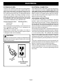
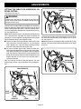
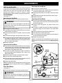
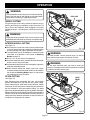
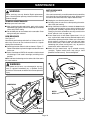
OPERATOR'S MANUAL
18 in. (457 mm) Variable Speed
SCROLL SAW
SC180VS
R
GE
RA
TO
ES
AD
BL
Your new Scroll Saw has been engineered and manufactured to Ryobi's high standards for dependability, ease of operation,
and operator safety. Properly cared for, it will give you years of rugged, trouble-free performance.
WARNING: To reduce the risk of injury, the user must read and understand the operator's manual.
Thank you for buying a Ryobi Scroll Saw.
SAVE THIS MANUAL FOR FUTURE REFERENCE
TABLE OF CONTENTS
■ Introduction and Product Specifications ...........................................................................................................................2
■ Rules for Safe Operation .............................................................................................................................................. 3-5
■ Electrical ............................................................................................................................................................................6
■ Glossary of Terms and Unpacking .................................................................................................................................. 7
■ Loose Parts and Tools Needed ....................................................................................................................................... 8
■ Features ............................................................................................................................................................................9
■ Assembly ........................................................................................................................................................................ 10
■ Adjustments .............................................................................................................................................................. 11-14
■ Operation .................................................................................................................................................................. 14-17
■ Maintenance ............................................................................................................................................................. 18-19
■ Troubleshooting ............................................................................................................................................................. 19
■ Parts Ordering / Service ................................................................................................................................................. 20
INTRODUCTION
Your saw has many features for making cutting operations
more pleasant and enjoyable. Safety, performance, and
dependability have been given top priority in the design of
this saw making it easy to maintain and operate.
CAUTION:
Carefully read through this entire operator's manual
before using your new saw. Pay close attention to the
Rules For Safe Operation and all Safety Alert Symbols
including Danger, Warning, and Caution. If you use your
saw properly and only for what it is intended, you will
enjoy years of safe, reliable service.
PRODUCT SPECIFICATIONS
SPECIFICATIONS:
Throat
18 in. (457 mm)
Blade Length
5 in. (127 mm) plain or pin
Motor Rating
120 volts, 60Hz, AC Only
No Load Speed
500 – 1600 Strokes Per Minute
Amperes
1.2
Net Weight
28 lbs. (14 kg.)
Look for this symbol to point out important safety precautions.
It means attention!!! Your safety is involved.
Page 2
RULES FOR SAFE OPERATION
Safe operation of this power tool requires that you read and
understand this operator's manual and all labels affixed to
the tool. Safety is a combination of common sense, staying
alert, and knowing how your scroll saw works.
READ ALL INSTRUCTIONS
■ KNOW YOUR POWER TOOL. Read the operator's
manual carefully. Learn the applications and limitations
as well as specific potential hazards related to this tool.
■ GUARD AGAINST ELECTRICAL SHOCK by preventing
body contact with grounded surfaces. For example:
pipes, radiators, ranges, refrigerator enclosures.
■ KEEP GUARDS IN PLACE and in working order. Never
operate the tool with any guard or cover removed. Make
sure all guards are operating properly before each use.
■ REMOVE ADJUSTING KEYS AND WRENCHES. Form
habit of checking to see keys and adjusting wrenches are
removed from tool before turning it on.
■ KEEP THE WORK AREA CLEAN. Cluttered work areas
and work benches invite accidents.
■ DON’T USE IN DANGEROUS ENVIRONMENTS. Do not
use power tools near gasoline or other flammable liquids,
in damp or wet locations or expose them to rain. Keep
work area well lighted.
■ KEEP CHILDREN AND VISITORS AWAY. All visitors
should wear safety glasses and be kept a safe distance
from work area.
■ MAKE WORKSHOP CHILDPROOF with padlocks,
master switches, or by removing starter keys.
■ DON’T FORCE THE TOOL. It will do the job better and
safer at the rate for which it was designed.
■ USE THE RIGHT TOOL. Do not force the tool or
attachment to do a job for which it was not designed.
■ USE THE PROPER EXTENSION CORD. Make sure
your extension cord is in good condition. When using an
extension cord, be sure to use one heavy enough to carry
the current your product will draw. An undersized cord will
cause a drop in line voltage resulting in loss of power and
overheating. A wire gauge size (A.W.G.) of at least 16 is
recommended for an extension cord 25 feet or less in
length. If in doubt, use the next heavier gauge. The
smaller the gauge number, the heavier the cord.
■ WEAR PROPER APPAREL. Do not wear loose clothing,
neckties, or jewelry that can get caught in the tool’s
moving parts and cause personal injury. Nonslip footwear
is recommended when working outdoors. Wear protective
hair covering to contain long hair.
■ ALWAYS WEAR SAFETY GLASSES WITH SIDE
SHIELDS. Everyday eyeglasses have only impactresistant lenses; they are NOT safety glasses.
■ SECURE WORK. Use clamps or a vise to hold work when
practical. It’s safer than using your hand and it frees both
hands to operate the tool.
■ DO NOT OVERREACH. Keep proper footing and balance
at all times.
■ MAINTAIN TOOLS WITH CARE. Keep tools sharp and
clean for best and safest performance. Follow instructions
for lubricating and changing accessories.
■ DISCONNECT ALL TOOLS. When not in use, before
servicing, or when changing attachments, blades, bits,
cutters, etc., all tools should be disconnected from power
source.
■ REDUCE THE RISK OF UNINTENTIONAL STARTING.
Be sure switch is off when plugging in.
■ USE RECOMMENDED ACCESSORIES. Consult the
operator’s manual for recommended accessories. The
use of improper accessories may cause risk of injury.
■ NEVER STAND ON TOOL. Serious injury could occur if
the tool is tipped or if the blade is unintentionally contacted.
■ CHECK DAMAGED PARTS. Before further use of the
tool, a guard or other part that is damaged should be
carefully checked to determine that it will operate properly
and perform its intended function. Check for alignment of
moving parts, binding of moving parts, breakage of parts,
mounting and any other conditions that may affect its
operation. A guard or other part that is damaged must be
properly repaired or replaced by an authorized service
center to avoid risk of personal injury.
■ DIRECTION OF FEED. Feed work into a blade or cutter
against the direction or rotation of the blade or cutter only.
■ NEVER LEAVE TOOL RUNNING UNATTENDED.
TURN POWER OFF. Don’t leave tool until it comes to a
complete stop.
■ DON’T ABUSE CORD. Never carry tool by the cord or
yank it to disconnect from receptacle. Keep cord from
heat, oil, and sharp edges.
■ PROTECT YOUR LUNGS. Wear a face or dust mask if
the cutting operation is dusty.
■ PROTECT YOUR HEARING. Wear hearing protection
during extended periods of operation.
■ BLADE COASTS AFTER TURN OFF.
■ KEEP TOOL DRY, CLEAN, AND FREE FROM OIL AND
GREASE. Always use a clean cloth when cleaning. Never
use brake fluids, gasoline, petroleum-based products, or
any solvents to clean tool.
■ INSPECT TOOL CORDS AND EXTENSION CORDS
PERIODICALLY and, if damaged, have repaired by a
qualified service technician. Stay constantly aware of cord
location and keep it well away from the rotating wheel.
■ NEVER USE IN AN EXPLOSIVE ATMOSPHERE. Normal
sparking of the motor could ignite fumes.
■ USE ONLY OUTDOOR EXTENSION CORDS with
approved ground connection that are intended for use
outdoors and so marked.
■ BE SURE THE BLADE PATH IS FREE OF NAILS.
Inspect for and remove nails from lumber before cutting.
Page 3
RULES FOR SAFE OPERATION
■ AVOID AWKWARD OPERATIONS AND HAND POSITIONS where a sudden slip could cause your hand to
move into the blade. ALWAYS make sure you have good
balance.
■ ALLOW THE MOTOR TO COME UP TO FULL SPEED
before starting a cut to avoid binding or stalling.
■ DO NOT USE TOOL IF SWITCH DOES NOT TURN IT
ON AND OFF. Have defective switches replaced by an
authorized service center.
■ REPLACEMENT PARTS. All repairs, whether electrical
or mechanical, should be made by qualified service
technician at an authorized service center.
■ WHEN SERVICING use only identical Ryobi replacement
parts. Use of any other parts may create a hazard or cause
product damage.
■ KEEP HANDS AWAY FROM CUTTING AREA. Do not
hand hold pieces so small that your fingers go under the
blade guard. Do not reach underneath work or in blade
cutting path with your hands and fingers for any reason.
■ FIRMLY CLAMP OR BOLT your saw to a stable, level
workbench or table. The most comfortable table height is
approximately waist height.
■ DO NOT FEED THE MATERIAL TOO QUICKLY. Do not
force the workpiece against the blade.
■ USE ONLY CORRECT BLADES. Use the right blade
size, style and cutting speed for the material and the type
of cut. Blade teeth should point down toward the table.
■ BEFORE MAKING A CUT, BE SURE ALL ADJUSTMENTS ARE SECURE.
■ ALWAYS SUPPORT LARGE WORKPIECES while cutting to minimize risk of blade pinching and kickback. Saw
may slip, walk or slide while cutting large or heavy boards.
■ DO NOT REMOVE JAMMED CUTOFF PIECES until
blade has stopped.
■ NEVER START THE TOOL when the blade is in contact
with the workpiece.
■ NEVER TOUCH BLADE or other moving parts during
use.
■ BEFORE CHANGING THE SETUP, REMOVING COVERS, GUARDS, OR BLADES, unplug the saw and
remove the switch key.
■ KEEP BLADES CLEAN, SHARP, AND WITH SUFFICIENT SET. Sharp blades minimize stalling and kickbacks.
■ ALWAYS TURN OFF SAW before disconnecting it to
avoid accidental starting when reconnecting to a power
source.
■ DO NOT OPERATE THIS TOOL WHILE UNDER THE
INFLUENCE OF DRUGS, ALCOHOL, OR ANY
MEDICATION.
■ STAY ALERT AND EXERCISE CONTROL. Watch what
you are doing and use common sense. Do not operate
tool when you are tired. Do not rush.
■ MAKE SURE WORK AREA HAS AMPLE LIGHTING to
see the work and that no obstructions will interfere with
safe operation BEFORE performing any work using your
saw.
■ SAVE THESE INSTRUCTIONS. Refer to them frequently
and use them to instruct other users. If you loan someone
this tool, loan them these instructions also.
WARNING:
Some dust created by power sanding, sawing, grinding,
drilling, and other construction activities contains
chemicals known to cause cancer, birth defects or
other reproductive harm. Some examples of these
chemicals are:
• lead from lead-based paints,
• crystalline silica from bricks and cement and other
masonry products, and
• arsenic and chromium from chemically-treated
lumber.
Your risk from these exposures varies, depending on
how often you do this type of work. To reduce your
exposure to these chemicals, work in a well ventilated
area, and work with approved safety equipment, such
as those dust masks that are specially designed to filter
out microscopic particles.
SAVE THESE INSTRUCTIONS
WARNING:
KEEP HANDS AWAY
FROM BLADE. FAILURE
TO HEED THIS WARNING
COULD RESULT IN
SERIOUS INJURY.
Page 4
RULES FOR SAFE OPERATION
The purpose of safety symbols is to attract your attention to possible dangers. The safety symbols, and the explanations
with them, deserve your careful attention and understanding. The safety warnings do not by themselves eliminate any
danger. The instructions or warnings they give are not substitutes for proper accident prevention measures.
SYMBOL
MEANING
SAFETY ALERT SYMBOL:
Indicates danger, warning or caution. May be used in conjunction with other symbols or pictographs.
DANGER: Failure to obey a safety warning will result in serious injury to yourself or to others. Always
follow the safety precautions to reduce the risk of fire, electric shock and personal injury.
WARNING: Failure to obey a safety warning can result in serious injury to yourself or to others. Always
follow the safety precautions to reduce the risk of fire, electric shock and personal injury.
CAUTION: Failure to obey a safety warning may result in property damage or personal injury to yourself
or to others. Always follow the safety precautions to reduce the risk of fire, electric shock and personal
injury.
Note:
Advises you of information or instructions vital to the operation or maintenance of the equipment.
IMPORTANT
Servicing requires extreme care and knowledge and should
be performed only by a qualified service technician. For
service we suggest you return the tool to your nearest
RYOBI AUTHORIZED SERVICE CENTER for repair. When
servicing, use only identical Ryobi replacement parts.
WARNING:
Do not attempt to operate this tool until you have read
thoroughly and understand completely all instructions,
safety rules, etc. contained in this manual. Failure to
comply can result in accidents involving fire, electric
shock, or serious personal injury. Save this operator's
manual and review frequently for continuing safe operation
and instructing others who may use this tool.
WARNING:
WEAR YOUR
SAFETY
GLASSES
FORESIGHT IS BETTER
THAN NO SIGHT
The operation of any power tool can result in foreign objects being thrown into your eyes, which
can result in severe eye damage. Before beginning tool operation, always wear safety goggles or
safety glasses with side shields and a full face shield when needed. We recommend Wide Vision
Safety Mask for use over eyeglasses or standard safety glasses with side shields. Always wear
eye protection which is marked to comply with ANSI Z87.1.
SAFETY AND INTERNATIONAL SYMBOLS
This operator’s manual describes safety and international symbols and pictographs that may appear on this product.
Read the operator’s manual for complete safety, assembly, operating and maintenance, and repair information.
MEANING
Do not expose to rain or use in damp locations
Page 5
ELECTRICAL
EXTENSION CORDS
ELECTRICAL CONNECTION
Use only 3-wire extension cords that have 3-prong grounding plugs and 3-pole receptacles that accept the tool's plug.
When using a power tool at a considerable distance from the
power source, use an extension cord heavy enough to carry
the current that the tool will draw. An undersized extension
cord will cause a drop in line voltage, resulting in a loss of
power and causing the motor to overheat. Use the chart
provided below to determine the minimum wire size required
in an extension cord. Only round jacketed cords listed by
Underwriter's Laboratories (UL) should be used.
Length of Extension Cord
Wire Size (A.W.G.)
Up to 25 feet
16
26-100 feet
16
When working with the tool outdoors, use an extension cord
that is designed for outside use. This is indicated by the
letters WA on the cord's jacket.
Before using an extension cord, inspect it for loose or
exposed wires and cut or worn insulation. Repair or replace
a damaged or worn cord immediately.
Your Ryobi Scroll Saw is powered by a precision built electric
motor. It should be connected to a power supply that is 120
volts, 60Hz, AC only (normal household current). Do not
operate this tool on direct current (DC). A substantial voltage
drop will cause a loss of power and the motor will overheat.
If the saw does not operate when plugged into an outlet,
double check the power supply.
CAUTION:
Keep the cord away from the cutting area and position the
cord so that it will not be caught on lumber, tools, or other
objects during cutting.
GROUNDING INSTRUCTIONS
In the event of a malfunction or breakdown, grounding
provides a path of least resistance for electric current to
reduce the risk of electric shock. This tool is equipped with an
electric cord having an equipment-grounding conductor and
a grounding plug. The plug must be plugged into a matching
outlet that is properly installed and grounded in accordance
with all local codes and ordinances.
Do not modify the plug provided. If it will not fit the outlet, have
the proper outlet installed by a qualified electrician. Improper
connection of the equipment-grounding conductor can result
in a risk of electric shock. The conductor with insulation
having an outer surface that is green with or without yellow
stripes is the equipment-grounding conductor. If repair or
replacement of the electric cord or plug is necessary, do not
connect the equipment-grounding conductor to a live terminal.
Check with a qualified electrician or service personnel if the
grounding instructions are not completely understood, or if in
doubt as to whether the tool is properly grounded.
Repair or replace a damaged or worn cord immediately.
This tool is intended for use on a circuit that has an outlet like
the one shown in Figure 1. It also has a grounding pin like the
one shown.
GROUNDING
PIN
COVER OF GROUNDED
OUTLET BOX
Fig. 1
Page 6
GLOSSARY OF TERMS FOR WOODWORKING
Bevel Cut
A cutting operation made with the saw table at any angle
other than 90˚ to the blade.
Compound Cut
A compound cut is a cut made using a miter angle and a
bevel angle at the same time.
Crosscut
A cutting or shaping operation made across the grain or the
width of the workpiece.
Freehand (for scroll saw)
Performing a cut without the workpiece being guided by a
fence or miter gauge. Work must supported by the table.
Gum
A sticky, sap based residue from wood products.
Kerf
The material removed by the blade in a through cut or the slot
produced by the blade in a non-through or partial cut.
Resin
A sticky, sap base substance that has hardened.
Ripping
A cutting operation along the length of the workpiece.
Saw Blade Path
The area directly in line — over, under, behind, or in front of
the blade. As it applies to the workpiece, that area which will
be, or has been, cut by the blade.
Set
The distance that the tip of the saw blade tooth is bent (or set)
outward from the face of the blade.
SPM
Strokes per minute. Used in reference to blade movement.
Through Sawing
Any cutting operation where the blade extends completely
through the thickness of the workpiece.
Nonferrous Metal
Metal that does not contain iron, such as aluminum, brass or
copper.
Throw-Back
Throwing of a workpiece in a manner similar to a kickback.
Usually associated with a cause other than the kerf closing,
such as a workpiece not being against the fence, being
dropped into the blade, or being placed inadvertently in
contact with the blade.
Push Stick
A device used to feed the workpiece through the saw blade
during narrow ripping type operations and helps keep the
operator's hands well away from the blade.
Workpiece
The item on which the cutting operation is being done. The
surfaces of a workpiece are commonly referred to as faces,
ends, and edges.
Resaw
A cutting operation to reduce the thickness of the workpiece
to make thinner pieces.
Worktable
The surface on which the workpiece rests while performing
a cutting or sanding operation.
Leading End
The end of the workpiece pushed into the cutting tool first.
UNPACKING
Your scroll saw comes completely assembled.
WARNING:
■ Carefully remove all parts from the shipping carton.
■ Do not discard the packing material until you have carefully
inspected the belt/disc sander, identified all parts, and
satisfactorily operated your new tool.
Do not allow familiarity with the tool to make you careless.
Remember that a careless fraction of a second is sufficient
to inflict severe injury.
■ If all parts have been included, proceed to assembly.
■ If any parts are damaged or missing, please call
1-800-525-2579 for assistance.
■ Examine all parts to make sure no breakage has occurred
during shipping. Any damaged or missing part should be
replaced before attempting to use the tool.
Note: If any parts are damaged or missing, do not attempt
to plug in the power cord and turn the switch on until the
damaged or missing parts are obtained and are installed
correctly.
WARNING:
Do not attempt to assemble this tool, plug in the power
cord, or turn on switch if any parts are damaged or missing.
Failure to heed this warning could result in serious
personal injury.
Page 7
LOOSE PARTS
Check all loose parts from the box with the list below. Assemble according to the instructions on the following pages.
■ Blade(s)
■ Operator's Manual (not shown)
PIN BLADE
PLAIN BLADE
Fig. 2
TOOLS NEEDED
The following tools (not included) are needed for adjustments and alignment:
■ Hex Key
■ Combination Square
■ Adjustable Wrench
■ Phillips Screwdriver
■ Slotted Screwdriver
ADJUSTABLE WRENCH
HEX KEY
PHILLIPS SCREWDRIVER
SMALL
COMBINATION
SQUARE
SLOTTED SCREWDRIVER
Fig. 3
Page 8
FEATURES
KNOW YOUR SCROLL SAW
On/Off Knob with Variable Speed
Before attempting to use your saw, familiarize yourself with
all the operating features and safety requirements of your
Ryobi scroll saw. See Figure 4.
This versatile, variable speed scroll saw is great for making
toys, puzzles, games, artwork, and jewelry. It is a handy doit-yourself tool. It cuts wood, wood composition products,
plastic, and other fibrous material up to 2 in. (51 mm) thick.
It also cuts nonferrous metals (aluminum, brass, copper).
Pull the knob out to turn ON the scroll saw and push the knob
in to turn OFF the scroll saw. Turn the knob to adjust the
speed from the high speed of approximately 1,600 SPM
(strokes per minute) to the low speed of approximately 500
SPM.
Sawdust Blower/Light
With an easy ON/OFF switch, the sawdust blower/light
keeps the line of cut on the workpiece clean and lighted for
more accurate scroll cuts. For best results, always direct air
flow at the blade and the workpiece.
Bevel Scale
The bevel scale and indicator show the degree the saw table
is tilted.
Sawdust Exhaust
Blade Clamp Screws
Blade clamp screws are used when changing saw blades.
This feature will allow you to attach any 1-1/4 in. (32 mm)
vacuum hose for easy sawdust collection.
Blade Storage Drawer
Saw Table with Throat Plate
Attached under the left side of the table is a blade storage
drawer. It will hold up to 20 blades.
Your scroll saw has an aluminum saw table with tilt control
for maximum accuracy. The throat plate, inserted in the saw
table, allows for blade clearance.
Blade Tension Knob
Loosen or tighten blade tension by turning the blade tension
knob.
Switch
Drop Foot and Drop Foot Lock Knob
Table Lock Knob
This foot should be lowered until it just rests on top of the
workpiece to prevent the workpiece from lifting, yet not so
much that the workpiece drags. The vertical portion provides
a blade guard to prevent accidental blade contact.
Allows you to tilt the table and lock it at the desired angle up
to 45°.
ON/OFF KNOB WITH
VARIABLE SPEED
A power switch that turns the sawdust blower/light on and off.
LIGHT SWITCH
BLADE
TENSION KNOB
DROP FOOT
LOCK KNOB
BLADE CLAMP
SCREWS
BLADE
TENSION LEVER
THROAT
PLATE
DROP
FOOT
R
SAW
BLADE
SAW
TABLE
SAWDUST
EXHAUST
E
AG
GE
ORA
DE ST
OR
E
ST
BLA
AD
BL
ARMATURE
ACCESS HOLE
SAWDUST
BLOWER / LIGHT
BLADE
STORAGE DRAWER
Page 9
BEVEL SCALE
TABLE
LOCK KNOB
Fig. 4
ASSEMBLY
Your Ryobi 18 in. (457 mm) Scroll Saw was fully assembled
at the factory. Before operating this tool, it is important to
check all alignments and settings. Normal handling during
shipment may have changed settings.
MOUNTING SCROLL SAW TO WORKBENCH
WARNING:
To avoid serious personal injury from unexpected tool
movement, always securely mount scroll saw to a
workbench.
If the scroll saw is to be used in a permanent application, we
recommend that you secure it in a permanent location such
as a workbench. When mounting the saw to a workbench,
holes should be drilled through the supporting surface of the
workbench.
■ Each hole in the base of the saw should be bolted
securely using machine bolts, washers, and nuts (not
included). Bolts should be of sufficient length to accommodate the saw base, washers, nuts, and the thickness
of the workbench.
■ Place scroll saw on workbench. Using the saw base as a
pattern, locate and mark the holes where the scroll saw is
to be mounted.
■ Drill four holes through the workbench.
■ Place scroll saw on workbench aligning holes in the saw
base with the holes drilled in the workbench.
■ Insert all four bolts (not included) and tighten securely
with washers and nuts (not included).
Note: All bolts should be inserted from the top. Install the
washers and nuts from the underside of the bench.
CLAMPING SCROLL SAW TO WORKBENCH
See Figure 5.
If the scroll saw is to be used in a portable application, it is
recommended that you fasten it permanently to a mounting
board that can easily be clamped to a workbench or other
supporting surface. The mounting board should be of
sufficient size to avoid tipping of saw while in use. Any good
grade plywood or chipboard with a 3/4 in. (19 mm) thickness
is recommended.
■ Mount saw to board using holes in saw base as a template
for hole pattern. Locate and mark the holes where scroll
saw is to be mounted.
■ Follow last three steps in previous section called
Mounting Scroll Saw to Workbench.
If lag bolts are being used, make sure they are long enough
to go through holes in the saw base and the material the saw
is being mounted to.
If machine bolts are being used, make sure they are long
enough to go through holes in the saw base, the material the
saw is being mounted to, and the washers and nuts.
Note: It may be necessary to countersink washers and nuts
on the bottom side of mounting board.
R
Supporting surface where scroll saw is mounted should be
examined carefully after mounting to insure that no movement during use can result. If any tipping or walking is noted,
secure workbench or supporting surface before beginning
cutting operations.
BL
AD
ORA
E ST
GE
Reducing Noise and Vibration:
You may wish to place a foam pad or piece of carpet between
the saw base and the workbench to help reduce noise and
vibration.
If a foam pad or piece of carpet is used, do not overtighten
the mounting bolts. Leave some cushion between the padding and the saw base to help absorb the noise and vibration.
The size of the padding material should be approximately
24 in. x 12 in. x 1/2 in. (610 mm x 305 mm x 13 mm).
Page 10
C-CLAMP
SAW BASE
C-CLAMP
WORKBENCH
MOUNTING
BOARD
Fig. 5
ADJUSTMENTS
SQUARING THE SAW TABLE TO THE BLADE
WARNING:
See Figures 7 and 8.
To prevent accidental starting that could cause possible
serious personal injury, turn off the saw and unplug the
saw from the power source before making any adjustments.
DROP FOOT
See Figure 6.
To prevent workpiece from lifting, the drop foot should be
adjusted so it just rests on the top of the workpiece. The drop
foot should not be adjusted so that the workpiece drags.
Always retighten the drop foot lock knob after each adjustment has been made.
■ Loosen the drop foot lock knob.
■ Lower or raise the drop foot to the desired position.
■ Retighten the drop foot lock knob.
The tall, front part of the drop foot acts as a blade guard to
prevent accidental contact with the blade.
LIGHT SWITCH
WARNING:
Failure to turn the saw off and unplug the saw from the
power source could result in accidental starting causing
possible serious injury.
■ Loosen the drop foot lock knob and move drop foot rod all
the way up. Retighten drop foot lock knob.
■ Loosen the table lock knob to tilt the saw table until it is
approximately perpendicular or at right angle to the
blade.
■ Place a small square on the saw table next to the blade.
■ Loosen the screw holding the scale indicator.
See Figure 8. Move indicator to the 0° mark and securely
tighten screw. Remember, the bevel scale is a convenient guide but should not be relied upon for precision.
Make practice cuts on scrap material to determine if your
angle settings are correct.
■ Adjust the drop foot to desired position and securely
retighten the drop foot lock knob.
DROP FOOT
LOCK KNOB
ON
R
OFF
DROP FOOT
LOCK KNOB
R
DROP
FOOT
DROP
FOOT ROD
DROP FOOT
SAWDUST
BLOWER / LIGHT
DROP
FOOT ROD
GE
RA
STO
DE
BLA
Fig. 6
SAWDUST BLOWER/LIGHT
E
AG
R
TO
ES
See Figure 6.
AD
BL
WARNING:
Failure to turn the saw off and unplug the saw from the
power source could result in accidental starting causing
possible serious injury.
With an easy ON/Off switch, the attached sawdust blower/
light is designed to direct air to the cutting line. Adjust the
sawdust blower/light to the desired position.
Page 11
SMALL
COMBINATION
SQUARE
E
ORAG
E ST
BLAD
TABLE
LOCK KNOB
Fig. 7
ADJUSTMENTS
SETTING THE TABLE FOR HORIZONTAL OR
BEVEL CUTTING
HEX BOLT
See Figures 8, 9 and 10.
WARNING:
Failure to turn the saw off and unplug the saw from the
power source could result in accidental starting causing
possible serious injury.
A bevel scale is located under the saw table as a convenient
guide for setting the approximate saw table angle for bevel
cutting. When greater precision is required, make practice
cuts on scrap material and adjust the saw table as necessary
for your requirements.
Note: When cutting at angles, the drop foot should be tilted
so it is parallel to the saw table and rests flat against the
workpiece. To tilt the drop foot, loosen phillips screw, tilt drop
foot to the proper angle, then retighten screw.
■ Loosen the table lock knob and push down on the right
side of the table. If the table stop at 0°, the zero degree
stop is properly set. If the table stops somewhere other
than zero, then adjust the zero degree stop.
■ To access the zero degree stop, loosen the table lock
knob, and tilt the table with the right side all the way down.
Just under the front of the saw table is the zero degree
stop. See Figure 9. Loosen the hex nut and rotate the hex
bolt to raise or lower the bolt as needed to adjust the zero
degree stop. Be sure to check to see that the table is
square to the blade.
Now, by returning the table to the zero position, the zero
degree stop provides a quick reference to the preset position.
HEX NUT
ZERO DEGREE
STOP ASSEMBLY
Fig. 9
The zero stop assembly can be rotated to the left and down
out of the way and the table can be angled up to 12˚ to the
left. See Figure 10.
Note: Make sure the zero degree stop is rotated all the way
down or it will contact the blade storage drawer as you angle
to the left.
ZERO DEGREE
STOP ASSEMBLY
ZERO DEGREE STOP
Fig. 10
TABLE LOCK
KNOB
BEVEL
SCALE
SCALE
INDICATOR
SCREW
Fig. 8
Page 12
ADJUSTMENTS
INSTALLING BLADES
Removing the Saw Blade:
Scroll saw blades wear out quickly and must be replaced
frequently for best cutting results. Expect to break some
blades while you learn to use and adjust your saw. Blades
generally stay sharp for 1/2 hour to 2 hours of cutting,
depending on the type of material and speed of operation.
■ Pull up on the tension release.
■ Turn blade tension knob counterclockwise to decrease
(or loosen) blade tension. See Figure 4.
Pin End Blades
See Figure 11.
Removing the Saw Blade:
■ Pushing up from under the saw table, remove the throat
plate.
■ Loosen both the upper and lower blade clamp screws.
■ Remove the blade.
Replacing the Saw Blade:
■ Turn off and unplug the saw from the power source.
WARNING:
Failure to turn the saw off and unplug the saw from the
power source could result in accidental starting causing
possible serious injury.
■ Pull up on the tension release.
■ Turn blade tension knob clockwise to decrease (or loosen)
blade tension. See Figure 4.
■ Pushing up from under the saw table, remove the throat
plate.
■ Loosen both the upper and lower blade clamp screws.
■ Pull up on the blade and push down on the saw arm to
disengage the upper pin in the V-notch of the upper blade
holder. Push the blade downward to disengage the lower
pin in the lower blade holder.
■ Remove the blade.
■ Place the new blade through the opening in the saw table
with the teeth to the front of the saw and pointing down
toward the saw table.
■ Position blade and tighten the blade clamp screw
securely.
■ Pull up on the blade and press the upper arm down to
position the upper end of the blade in the upper blade
holder.
■ Securely tighten the upper blade clamp screw.
■ Push the tension release back down.
■ Turn the blade tension knob clockwise until the blade has
the desired amount of tension.
■ Replace the throat plate.
Note: If the blade touches the drop foot on either side then
the drop foot must be adjusted. See section Adjusting Drop
Foot.
Replacing the Saw Blade:
■ Place the new blade through the opening in the saw table
with the teeth to the front of the saw and pointing down
toward the saw table. The pins on the blade go under the
blade holder in the lower blade holder.
■ Pull up on the blade and press the upper arm down to
position the upper end of the blade in the V-notch in the
upper blade holder.
■ Securely tighten the upper and lower blade clamps .
■ Push the tension release back down.
■ Turn the blade tension knob counterclockwise until the
blade has the desired amount of tension.
■ Replace the throat plate.
Note: If the blade touches the drop foot on either side then
the drop foot must be adjusted. See section on Adjusting
Drop Foot.
TENSION
RELEASE
V-NOTCH
SAW
BLADE
BLADE
TENSION
KNOB
BLADE
CLAMP
SCREW
Fig. 11
Plain End Blades
See Figure 11.
■ Turn off and unplug the saw from the power source.
WARNING:
Failure to turn the saw off and unplug the saw from the
power source could result in accidental starting causing
possible serious injury.
Page 13
ADJUSTMENTS
WARNING:
Failure to turn the saw off and unplug the saw from the
power source could result in accidental starting causing
possible serious injury.
ADJUSTING DROP FOOT
■ Loosen the drop foot lock knob. See Figure 4, page 9.
■ Center the drop foot around the saw blade to the desired
position.
■ Tighten the drop foot lock knob.
Check tension by the sound the blade makes when plucked
like a guitar string. This method of adding tension to the blade
can be developed with practice and requires knowing your
scroll saw.
■ Pluck the back straight edge of blade while turning
tension adjusting knob. Sound should be a musical note.
Sound becomes less flat as tension increases. Sound
decreases with too much tension.
Note: Be careful not to adjust blade too tight. Too much
tension may cause the blade to break as soon as you start
cutting. Too little tension may cause the blade to bend or
break before the teeth wear out.
ADJUSTING BLADE TENSION
See Figure 12.
■ Turn off and unplug the saw from the power source.
WARNING:
BLADE
TENSION KNOB
Failure to turn the saw off and unplug the saw from the
power source could result in accidental starting causing
possible serious injury.
■ Turning the blade tension knob clockwise decreases (or
loosens) blade tension.
■ Turning the blade tension knob counterclockwise
increases (or tightens) blade tension.
Note: Adjustments to blade tension can be made at any
time.
Fig. 12
OPERATION
BASIC OPERATION OF THE SCROLL SAW
Before starting a cut, watch the saw run. If you experience
excessive vibration or unusual noise, stop immediately. Turn
the saw off, remove the switch key, and unplug the saw. Do
not restart until locating and correcting the problem.
Note: After the saw is turned ON, a hesitation before blade
movement is normal.
CUTTING PROCEDURES
■ There is a learning curve for each person who wants to
use this saw. During that period of time it is expected that
some blades will break until you learn how to use and
adjust the saw.
■ Plan the way you will hold the workpiece from start to
finish.
■ Keep your hands away from the blade. Do not hand hold
pieces so small your fingers will go under the blade guard.
■ Hold the workpiece firmly against the saw table.
■ The blade teeth cut material only on the down stroke.
■ Use gentle pressure and both hands when feeding the
work into the blade. Do not force the work.
■ Guide the workpiece into the blade slowly because the
teeth of the blade are very small and can only remove
material on the down stroke.
■ Avoid awkward operations and hand positions where a
sudden slip could cause serious injury from contact with
the blade. Never place hands in blade path.
■ To get accurate cuts, compensate for the blade's
tendency to follow the wood grain as you are cutting
wood.
■ Use extra supports (tables, saw horses, blocks, etc.)
when cutting large, small or awkward workpieces.
■ Never use another person as a substitute for a table
extension or as additional support for a workpiece that is
longer or wider than the basic saw table.
■ When cutting irregularly shaped workpieces, plan your
work so it will not pinch the blade. Workpieces must not
twist, rock or slip while being cut.
Page 14
OPERATION
REMOVING JAMMED MATERIAL
ON/OFF KNOB WITH VARIABLE SPEED
When backing out the workpiece, the blade may bind in the
kerf (cut). This is usually caused by sawdust clogging the
kerf or when the blade comes out of the blade holders. If this
happens:
■ Wait until the saw has come to a full and complete stop.
■ Place the switch in the OFF position.
■ Unplug the saw from the power source.
See Figure 13.
Your scroll saw has an easy access ON/OFF knob with
variable speed.
■ Pull the knob out to turn ON the saw, and push the knob
in to turn OFF the saw.
Note: After saw is turned on, a hesitation before blade
movement is normal.
■ Remove the saw's blade and the workpiece, see section on
Removing the Saw Blade, page 13.
■ Wedge the kerf open with a flat screwdriver or wooden
wedge then remove the blade from the workpiece.
WARNING:
Before removing loose pieces from the table, turn saw off
and wait for all moving parts to stop to avoid serious
personal injury.
AVOIDING INJURY
■ Make sure saw is level and does not rock. Saw should
always be on a firm, level surface with plenty of room for
handling and properly supporting the workpiece.
■ Bolt saw to the support surface to prevent slipping,
walking or sliding during operations like cutting long,
heavy boards.
■ Turn saw off, remove switch key, and unplug cord from
the power source before moving the saw.
■ Do not remove jammed cutoff pieces until blade has come
to a full and complete stop.
■ Choose the right size and style blade for the material
and type of cut you plan to do.
■ Use only recommended accessories.
■ With the exception of the workpiece and related support
devises, clear everything off the saw table before turning
the saw on.
■ Properly support round materials such as dowel rods or
tubing because they have a tendency to roll during a cut
causing the blade to “bite”. To avoid this, always use a
“V” block or clamp workpiece to a miter gauge
■ Before removing loose pieces from the saw table, turn
saw off and wait for all moving parts to stop.
WARNING:
Never leave the saw unattended until the blade has come
to a complete stop to prevent serious personal injury.
■ By turning the knob, the variable speed control may be
adjusted from the high speed of approximately 1600 SPM
(Strokes Per Minute) to the low speed of approximately
500 SPM. Suggested speeds are identified under Choice
of Blade and Speed, page 16. Turn the On/Off knob to the
right or clockwise to increase strokes per minute and to
the left or counterclockwise to reduce the strokes per
minute.
This motor has an electronic control that regulates the speed
and provides overload protection to the motor. If the motor
fails to start after about two seconds, push the knob OFF and
disconnect the saw from the power source. Refer to the
troubleshooting chart.
Note: If the internal overload protector has been tripped,
pushing the On/Off knob OFF will reset it.
SPM
SPEED
INDICATOR
SWITCH
ON
1600
OFF
TO
DECREASE
1000
R
750
TO
INCREASE
500
E
AG
OR
ST
DE
Page 15
1250
Fig. 13
OPERATION
CHOICE OF BLADE AND SPEED
The scroll saw accepts a wide variety of blade widths and thicknesses for cutting wood and other fibrous materials. Your saw
uses 5 in. long blades of either the pin end or the plain end style. The blade width and thickness and the number of teeth per
inch to use are determined by the type of material and the size of the radius being cut.
Note: As a general rule, always select narrow blades for intricate curve cutting and wide blades for straight and large curve
cutting.
Teeth/Inch
Width
Thickness
Speed or
Strokes Per
Minute
10
.110 in.
(2.8 mm)
.020 in.
(0.5 mm)
500-1600
7
.067 in.
(1.1 mm)
.020 in.
(0.5 mm)
750-1250
13
.037 in.
(0.5 mm)
.015 in.
(0.4 mm)
500-1000
Material Cut
Popular size for cutting hard and soft
woods 3/16 in. (4.8 mm) up to 2 in. (51 mm)
Plastics, paper, felt, bone, etc.
Wood, plastics, extremely thin cuts on
materials 3/32 in. (2.4 mm) to 1/2 in.
(13 mm) thick.
For tight radius work in thin materials
3/32 in. (2.4 mm) to 1/8 in. (3 mm) wood,
veneer, bone, fiber, ivory, plastic, etc.
LOCK POST
BLADE INFORMATION
■ Scroll saw blades wear out and must be replaced frequently for best cutting results. Scroll saw blades generally stay sharp for 1/2 hour to 2 hours of cutting, depending on type of material and speed of operation.
■ In cutting wood, best results are achieved when cutting
wood less than one inch thick.
■ When cutting wood thicker than one inch, the user must
guide the workpiece very slowly into the blade and take
extra care not to bend or twist the blade while cutting.
■ When choosing a blade, carefully consider the following:
• Very fine, narrow blades should be used to scroll cut in
thin material 1/4 in. (6 mm) thick or less.
• Most blade packages state the size or thickness and
type of material which that blade is intended to cut. The
package should also state the radius or size of curve
that can be cut with that blade size.
• Wider blades cannot cut curves as tight or as small as
thinner blades.
■ Blades wear faster when:
• Cutting plywood, hardwood, and other laminates.
• Cutting material thicker than 3/4 in. (19 mm).
• Side pressure is applied to the blade.
R
PADLOCK
Fig. 14
LOCK POST
See Figure 14.
To prevent unauthorized use of your scroll saw, we suggest
that you disconnect it from the power supply and lock the
knob in the OFF position. A padlock should be used. When
the lock is installed and locked, as illustrated, the switch is
inoperable. Store the padlock key in another location.
■ To lock the saw in the OFF position, install a padlock
through the lock post beside the knob as illustrated and
lock the padlock. (Padlock is not supplied with the saw.)
ON / OFF KNOB
WARNING:
For your own safety, always push the knob OFF when
machine is not in use. Also, in the event of a power failure,
push knob OFF. Lock the scroll saw switch OFF with a
padlock. This will prevent the machine from starting up
again when the power comes back on. Failure to heed this
warning can result in serious personal injury.
Page 16
OPERATION
WARNING:
To avoid possible serious injury from accidental starting,
always turn the saw off and unplug the saw from power
source before removing or replacing the blade.
DRILL HOLE
R
INTERIOR
CUT
SCROLL CUTTING
For general type scroll cutting, follow the pattern lines by
pushing and turning the workpiece at the same time. Do
not try to turn the workpiece while engaged in the blade
without pushing it – the workpiece could bind or twist the
blade.
WARNING:
To prevent serious personal injury, never leave the saw
unattended until the blade has come to a complete stop.
GE
RA
TO
ES
AD
BL
INTERIOR SCROLL CUTTING
See Figure 15.
■ One feature of a scroll saw is that it can be used to make
scroll cuts on the interior of a workpiece without breaking
or cutting through the edge or perimeter of the board.
■ To make interior cuts in the workpiece, remove the scroll
saw blade as explained in the section on Installing
Blades on page 13.
■ Drill a 1/4 in. (6 mm) hole in the workpiece.
■ Place the workpiece on the saw table with the drilled hole
over the access hole in the table.
■ Install blade through the hole in the workpiece; adjust the
drop foot and blade tension.
■ When finished making the interior scroll cuts, simply
remove the blade from the blade holders as described in
the section on Installing Blades, page 13, and remove
the workpiece from the saw table.
WORKPIECE
Fig. 15
WARNING:
To avoid possible, serious personal injury, do not cut
more than one loose piece of material at a time.
WARNING:
Do not allow familiarity with your saw to make you
careless. Remember that a careless fraction of a second
is sufficient to inflict severe injury.
R
STACK CUTTING
WOOD
PIECES
See Figure 16.
After becoming well acquainted with your saw through
practice and experience, you may wish to try stack cutting.
Stack cutting may be used when several identical shapes
need to be cut. Several pieces of wood may be stacked on
top and secured to each other before cutting. The wood
pieces may be joined together by placing double sided tape
between each piece or by wrapping masking tape around the
corners or ends of the stacked wood. You must attach the
stacked pieces of wood to each other so they will move on
the table as a single piece of material.
BL
E
AD
OR
ST
AG
E
TAPE
Fig. 16
Page 17
MAINTENANCE
MOTOR BRUSHES
WARNING:
When servicing, use only identical Ryobi replacement
parts. Use of any other part may create a hazard or cause
product damage.
GENERAL MAINTENANCE
■ Keep your scroll saw clean.
■ After cleaning the table top initially, apply a thin coat of
automobile type (paste) wax to the table top so the wood
slides easily while cutting.
■ Do not allow pitch to accumulate on the saw table. Clean
with gum and pitch remover.
ARM BEARINGS
See Figure 17.
Lubricate the arm bearings after the first 10 hours of use. Oil
after every 50 hours of use or whenever there is a squeak
coming from the bearings.
■ Carefully place the saw on its side as shown in Figure 17.
Remove the rubber cap from the upper and the lower arm
of the saw.
■ Squirt a few drops of SAE20 oil around the shaft end and
arm bearings. Let oil soak in overnight, remaining in this
position.
Note: Lubricate the bearings on the other side of the saw in
this same manner.
See Figure 18.
Your saw has externally accessible motor brush assemblies
that should be checked periodically for wear. When one of
the two brushes becomes worn, replace both brushes.
■ Unplug the saw from the power source.
■ Carefully place the saw on its side exposing the underside of the saw housing.
■ Using a flat blade screwdriver, remove the bottom brush
assembly cap through the access hole in the base and
the top brush assembly cap from the top of the motor.
Gently pry the brush assemblies out using a small screw
drivier, point of a nail, or paper clip.
■ If one motor brush is worn down shorter than 1/4 in. (6
mm), replace both motor brushes. Do not replace one
side without replacing the other. Make sure curvature of
brush matches curvature of motor and that the motor
brush moves freely in brush tube. Use the blunt end of
something thin (eraser end of pencil, etc.) to push the
motor brush into the tube until it stays.
■ Make sure the motor brush cap is oriented correctly
(straight). Tighten motor brush cap using a hand
powered screwdriver only. Do not overtighten.
WARNING:
If the power cord is worn, cut, or damaged in any way,
have it replaced immediately by a qualified service
technician. Failure to do so could result in serious personal
injury.
BLA
TO
DE S
RAG
E
ARM BEARING
MOTOR
BRUSH
BRUSH
CAP
Fig. 18
ARM BEARING
Fig. 17
Page 18
MAINTENANCE
WARNING:
WARNING:
To prevent accidental starting that could cause possible
serious personal injury, turn off and unplug the saw
before maintaining or lubricating your scroll saw.
Failure to unplug your saw could result in accidental
starting causing serious injury.
TROUBLESHOOTING
WARNING:
For your own safety, turn saw OFF and remove plug from power outlet before adjusting or aligning your scroll
saw.
PROBLEM
Motor will not run.
CAUSE
SOLUTION
1. Problem with ON-OFF switch,
power cord, or outlet.
2. Motor defective.
Blades breaking.
1. Too much tension.
2. Feeding too quickly.
3. Wrong blade.
4. Blade twisting in wood.
Vibration (there is always
some vibration when the saw
is running).
Blade runout (blade not
properly aligned with arm
motion).
1. Have worn parts replaced before using
Scroll Saw again. Have the proper
outlet installed by a qualified electrician.
2. Do not attempt any repair. Have
repaired by a qualified service
technician.
1. Adjust tension.
2. Reduce feed rate.
3. Narrow blades for cutting thin wood or
tight corners and turns, wide blades for
thicker wood or wide turns.
4. Reduce side pressure on blade, check
blade tension.
1. Improper mounting of saw.
2. Mounting surface.
3. Loose table or table resting
against motor.
4. Loose motor mounting.
1. Check mounting.
2. Check mounting in manual.
3. Tighten table lock knob.
1. Blade holders out of line.
1. Realign blade.
Page 19
4. Tighten mounting screws.
OPERATOR'S MANUAL
18 in. (457 mm) Variable Speed Scroll Saw
SC180VS
EXTENSION CORD CAUTION
**Ampere rating
When using a power tool at a considerable distance from a power
source, be sure to use an extension cord that has the capacity to
handle the current the tool will draw. An undersized cord will
cause a drop in line voltage, resulting in overheating and loss of
power. Use the chart to determine the minimum wire size
required in an extension cord. Only round jacketed cords should
be used.
When working with a tool outdoors, use an extension cord that is
designed for outside use. This is indicated by the letters "WA" on
the cord's jacket.
Before using any extension cord, inspect it for loose or exposed
wires and cut or worn insulation.
(on tool data plate)
0-2.0
Cord Length
2.1-3.4
3.5-5.0
5.1-7.0
7.1-12.0 12.1-16.0
Wire Size (A.W.G.)
25'
16
16
16
16
14
14
50'
16
16
16
14
14
12
100'
16
16
14
12
10
—
CAUTION: Keep the extension cord clear of the working
area. Position the cord so that it will not get caught on workpiece,
tools, or other obstructions while you are working with a power
tool.
**Used on 12 gauge - 20 amp circuit.
• SERVICE
Now that you have purchased your tool, should a need ever exist for repair parts or
service, simply contact your nearest Ryobi Authorized Service Center. Be sure to
provide all pertinent facts when you call or visit. Please call 1-800-525-2579 for your
nearest Ryobi Authorized Service Center. You can also check our web site at
www.ryobitools.com for a complete list of Authorized Service Centers.
• MODEL NO.
The model and serial numbers of your tool will be found on a plate attached to the motor
housing. Please record the serial number in the space provided below.
•
MODEL NUMBER
•
SERIAL NUMBER
SC180VS
RYOBI TECHNOLOGIES, INC.
1428 Pearman Dairy Road
Anderson, SC 29625
Post Office Box 1207
Anderson SC 29622-1207
Phone 1-800-525-2579
www.ryobitools.com
983000-016
7-02