1
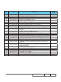
SERVICE MANUAL
EX612/EX615
Date
Revise Version
Description
2009.07.08
V1.0
Initial Issue
2009.10.13
V2.0
Add EX540/EX762
2009.12.16
V3.0
Add EX540I/EX542I
2010.01.30
V4.0
Add ES523ST/EW533ST;
Modify “Defect specification table” in Chapter 4;
2010.05.20
V5.0
Delete �����������������������������������������
EX540/EX762/EX540I/EX542I/ES523ST/EW533ST
Copyright May, 2010. All Rights Reserved
Prepare:
Mina
Check:
Approved:
Preface
This manual is applied to EX612/EX615 projection system. The manual gives you a brief
description of basic technical information to help in service and maintain the product.
Your customers will appreciate the quick response time when you immediately identify
problems that occur with our products. We expect your customers will appreciate the
service that you offer them.
This manual is for technicians and people who have an electronic background. Please
send the product back to the distributor for repairing and do not attempt to do anything that
is complex or is not mentioned in the troubleshooting.
Notice: The information found in this manual is subject to change without prior notice. Any
subsequent changes made to the data herein will be incorporated in future edition.
EX612/EX615 Service Manual
Copyright May. 2010
All Rights Reserved
Manual Version 5.0
EX612/EX615
Confidential
I
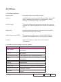
EX612/EX615 Comparison List
Parts
EX615
EX612
USER’S GUIDE
36.8EF01G001
36.8FK01G001
OPTICAL
ENGINE MODULE
70.8EF40GR01
70.8FK03GR01
MAIN BOARD
MODULE
70.8EF43GR01
80.8FK01G001
IO COVER
MODULE
70.8EF44GR01
70.8FK02GR01
EX612/EX615
Confidential
II
Table of Content
Chapter 1
Introduction
Highlight
1-1
Compatible Mode
1-3
Chapter 2 Disassembly Process
Equipment Needed & Product Overview
2-1
Disassemble Lamp Cover Module
2-2
Disassemble Lamp Module
2-2
Disassemble Focus Ring
2-3
Disassemble Top Cover Module
2-3
Disassemble Keypad Board Module and Zoom Ring
2-4
Disassemble Top Shielding
2-5
Disassemble Main Board Module
2-5
Disassemble Daughter Board and Lan Module Board
2-8
Disassemble Engine Module
2-9
Disassemble Color Wheel Module
2-9
Disassemble DMD Chip and DMD Board
2-10
Disassemble Rod Module
2-10
Disassemble System Fan Module and Thermal Switch
2-11
Disassemble Speakers
2-12
Disassemble Blower
2-13
Disassemble Front IR Module
2-14
Disassemble LVPS Module and Interlock Switch
2-14
Disassemble Lamp Driver Module
2-15
Disassemble Security Bar Cap
2-15
Disassemble Bottom Shielding
2-16
EX612/EX615
Confidential
III
Disassemble IO Cover
2-17
Rod Adjustment
2-18
Re-write Lamp Usage Hour
2-19
Chapter 3 Troubleshooting
LED Lighting Message
3-1
Main Procedure
3-2
Chapter 4 Function Test & Alignment Procedure
Test Equipment Needed
4-1
Service Mode
4-1
OSD Reset
4-1
Test Condition
4-2
Defect specification table
4-3
Test Inspection Procedure
4-3
Factory Fan RPM Reset
4-4
PC MODE
4-5
Video Performance
4-8
ADC Calibration
4-11
Optical Performance Measure
4-13
Network Function Test(For EX615)
4-15
Others
4-18
Chapter 5 Firmware Upgrade
Section 1: System Firmware Upgrade
5-1
Equipment Needed
5-1
DLP Composer Lite Setup Procedure
5-2
Setup Procedure
5-4
EX612/EX615
Confidential
IV
USB Driver Upgrade Procedure
5-4
Firmware Upgrade Procedure
5-5
Section 2: 8051 Firmware Upgrade Procedure
5-6
Equipment Needed
5-6
NLINK Setup Procedure
5-9
Manley USB Driver Upgrade Procedure
5-11
8051 Firmware Upgrade Prodedure
5-13
Section 3: Network Firmware Upgrade Procedure
(For EX615)
5-15
Equipment Needed
5-15
Write Down Projector IP
5-16
Network Setting
5-17
PC Hardware Link
5-18
Chapter 6 EDID Upgrade
EDID Introduction
6-1
Equipment Needed
6-2
Setup Procedure(VGA)
6-3
EDID Key-In Procedure(VGA-1 & VGA-2)
6-3
Setup
�����������������������������������������������������������
Procedure(HDMI)(For EX615)
6-6
EDID Key-In Procedure (HDMI)(For EX615)
Appendix A Exploded Image
6-6
I
Appendix B
EX612/EX615
Confidential
V
Serial Number System Definition
I
PCBA Code Definition
II
EX612/EX615
Confidential
VI
Chapter 1
Introduction
1-1 Highlight
No
Item
Description
1
Technology
● 0.55” XGA 2xLVDS SERIES 450 DMD DC3
2
Dimension
(W x D x H)
● 324 x 234 x 97 mm
3
Weight
● 6.3-6.4 lbs
4
Power Supply
● Auto-ranging: 100V~ 240V ± 10%, 50~ 60Hz
5
Keystone
Correction
● +/-40
�����������������������
degree (TI spec.)
6
Resolution
● Native Resolution: 1024 x 768
7
Power consumption
● Full Mode:(Typ)298W,(Max)328W @ac 110V
● ECO Mode:(Typ)247W,(Max)272W @ac 110V
8
Throw ratio
● 1.95~ 2.15 @60”(Distance/Width)
9
Projection lens
● YM09X/FPL30, F# 2.41~ 2.55 @60”, f= 21.8 ~ 24 mm @60”
10
Lamp life
● 2500 Hours, 50% Survival Rate (Standard-Mode)
● 4000 Hours, 50% Survival Rate (ECO-Mode)
11
Offset
● 115% ± 5%
12
Video compatibility
● NTSC: NTSC M 3.58 MHz, 4.43 MHz
● PAL: PAL B/D/G/H/I/M/N, 4.43 MHz
● SECAM: SECAM B/D/G/K/K1/L, 4.25/4.4 MHz
● Component: 480i/p, 576i/p, 720p (50/60Hz), 1080i/p (50/60Hz)
13
Aspect ratio
● 4:3, 16:9 I, 16:9 II, NATIVE, AUTO
14
Lamp
● 230 W OSRAM Lamp E20.8 elliptic
15
Color Wheel
● 5 Segments; RGBYW; Filter Diameter 40 mm
● R76Y32G78W98B76
● 2x, 7200 RPM
16
System Controller
● DDP2430
EX612/EX615
Confidential
1-1
No
Item
17
Input Connections
18
Temperature
19
Altitude
Description
● VGA-in: VGA in 1 (wireless dongle, YPbPr)
VGA in 2 (SCART, YPbPr)
● Composite: RCA x 1
● S-video: Mini-DIN 4 pin x 1
● Audio-in (Green coded port):
• Audio-in 1 only (Daughter Board) (for EX612)
• Audio-in 1, 2, 3 (Daughter Board) (for EX615)
● HDMI: HDMI v1.3 (HDCP) (for EX615)
● Audio-in connectivity grouping (for EX615)
• VGA-in1 -> Audio in1
• VGA-in2 -> Audio in2
• Composite/S-Vidoe -> Audio in3
● Operating ( Full-power-mode): 5~ 40 °C
● Non-operation (storage): -10°C~ 60°C
● Operating:
����������
0 ~ 2,500 ft, for 5°C~ 40°C
2500 ft ~ 5,000 ft, for 5°C~ 35°C
5,000 ft ~ 10,000 ft, for 5°C~ 30°C
EX612/EX615 Confidential
1-2
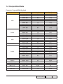
1-2 Compatible Mode
Computer Compatibility (Analog)
Compatibility
Resolution
V-Sync [Hz]
H-Sync [KHz]
640 x 350
70
31.5
640 x 350
85
37.9
640 x 400
85
37.9
640 x 480
640 x 480
640 x 480
640 x 480
720 x 400
720 x 400
800 x 600
800 x 600
800 x 600
800 x 600
800 x 600
1024 x 768
60
72
75
85
70
85
56
60
72
75
85
60
31.5
37.9
37.5
43.3
31.5
37.9
35.2
37.9
48.1
46.9
53.7
48.4
1024 x 768
70
56.5
1024 x 768
75
60
1024 x 768
1280 x 768
1152 x 864
1152 x 864
85
60
60
70
68.7
47.8
53.5
63.8
1152 x 864
75
67.5
1152 x 864
85
77.1
1280 x 1024
60
63.98
1280 x 1024
75
79.98
1280 x 1024
85
91.1
1280 x 960
60
60.0
WXGA
SXGA+
UXGA
1280 x 800
1400 x 1050
1600 x 1200
60
60
60
49.68
63.98
75
MAC LC 13”
640 x 480
66.66
34.98
MAC II 13”
640 x 480
66.68
35
MAC 16”
832 x 624
75
49.725
MAC 19”
1024 x 768
75
60.24
VGA
SVGA
XGA
WXGA
SXGA
EX612/EX615 Confidential
1-3
Compatibility
Resolution
V-Sync [Hz]
H-Sync [KHz]
MAC
1152 x 870
75
68.68
MAC G4
640 x 480
60
31.35
i Mac DV
1024 x 768
75
60
i Mac DV
1152 x 870
75
68.49
i Mac DV
1280 x 960
75
75
Computer Compatibility (Digital)
Compatibility
VGA
SVGA
XGA
WXGA
Resolution
V-Sync [Hz]
H-Sync [KHz]
640 x 350
70
31.5
640 x 350
85
37.9
640 x 400
85
37.9
640 x 480
640 x 480
640 x 480
640 x 480
720 x 400
720 x 400
800 x 600
800 x 600
800 x 600
800 x 600
800 x 600
1024 x 768
60
72
75
85
70
85
56
60
72
75
85
60
31.5
37.9
37.5
43.3
31.5
37.9
35.2
37.9
48.1
46.9
53.7
48.4
1024 x 768
70
56.5
1024 x 768
75
60
1024 x 768
1280 x 768
1280 x 800
85
60, 75, 85
60
68.7
47.8
49.64
EX612/EX615 Confidential
1-4
Compatibility
SXGA
SXGA+
UXGA
Resolution
V-Sync [Hz]
H-Sync [KHz]
1152 x 864
60
53.5
1152 x 864
70
63.8
1152 x 864
75
67.5
1152 x 864
85
77.1
1280 x 1024
60
63.98
1280 x 1024
75
79.98
1280 x 1024
85
91.1
1400 x 1050
1600 x 1200
60
60
63.98
75
Note: If the Computer Compatibility supportive signal is different from User's Manual, please refer to User's Manual.
EX612/EX615 Confidential
1-5
Chapter 2
Disassembly Process
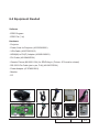
2-1 Equipment Needed & Product Overview
1. Screw Bit (+): 105
2. Screw Bit (+): 107
3. Screw Bit (-): 107
4. Hex Sleeves 5 mm
5. Tweezers
6. Projector
* Before you start: This process is protective level II. Operators should wear electrostatic chains.
* Note: - If you need to replace the Main Board, you have to record the Lamp Usage Hour.
- The disassembly process for EX612/EX615 is the same,we take EX615 as an example
here.
EX612/EX615 Confidential
2-
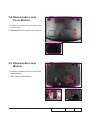
2-2 Disassemble Lamp
Cover Module
1. Loosen 2 screws (as red circle) on the
Lamp Cover.
2. Disassemble the Lamp Cover Module.
2-3 Disassemble Lamp
Module
1. Loosen 2 screws (as red circle) on the
Lamp Module.
2. Take off the Lamp Module.
EX612/EX615
Confidential
2-
2-4 Disassemble Focus Ring
1. Rotate the Focus Ring clockwise until you cannot rotate any more (as red arrow direction).
2. Pull out the Focus Ring.
Note: - When you assemble the Focus Ring, ensure the 3 card slot (as green square)
placed in the 3 double-screw bolt (as yellow circle) properly, and the Focus Ring can be well adjusted.
2-5 Disassemble Top Cover
Module
1. Unscrew 2 screws (as red circle) from the
Bottom Cover.
2. Press two sides of the projector as the
blue arrows point.
3. Remove the Top Cover Module.
EX612/EX615
Confidential
2-
Note: - When you remove the Top Cover, take care the connector (as yellow square) of FPC cable which connect Main Board and Keypad Board Module, then unplug it from Keypad Board
Module.
- Avoid damaging by pulling keypad FPC cable.
- Make sure the FPC cable plug into the correct ports when assembling it.
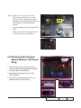
2-6 Disassemble Keypad
Board Module and Zoom
Ring
1. Unscrew 4 screws (as blue circle) to disassemble the Keypad Board Module from the Top Cover Module.
2. Separate the Keypad from the Top Cover Module.
3. Unscrew 3 screws (as red circle) to disassemble the Zoom Ring.
Keypad Board
Keypad
Zoom Ring
EX612/EX615
Confidential
2-
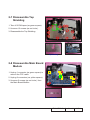
2-7 Disassemble Top
Shielding
1. Tear off 2 EMI tapes (as green square).
2. Unscrew 12 screws (as red circle).
3. Disassemble the Top Shielding.
Top Shielding
2-8 Disassemble Main Board
Module
1. Unplug 1 connector (as green square) to remove the FPC cable.
2. Unplug 8 connectors (as yellow square).
3. Unscrew 5 screws (as red circle) from the Main Board Module.
FPC cable
EX612/EX615
Confidential
2-
4. Unscrew 1 screw (as blue circle) from the IO Cover.
5. Unscrew 8 hex screws (as green circle) from the IO Cover.
6. Unplug 1 connector (as orange square).
7. Separate the Main Board Module and Main Board Shielding.
Note: - Make sure cables plug into the correct ports when assembling the unit.
Main Board Shielding
EX612/EX615
Confidential
2-
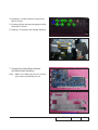
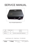
Please refer to the table as below for
details of each connector.
G
Male Connector
on Main Board
Item
F E
The key feature
Speaker
Compose of Red/Black Wire and
Black wire tube (2 pin)
B
Lamp Driver
Black wire tube (5 pin)
C
System Fan
Compose of Red/Yellow/Black
Wire (3 pin)
D
Photo Sensor
Compose of Red/Black/White
Wire and Black wire tube (3 pin)
E
Blower
Compose of Black/Yellow/Red
Wire and Blue wire tube (3 pin)
F
IR
A&G
D
CB
A
Figure
Compose of Black/Yellow/Red
Wire and Gray wire tube (3 pin)
EX612/EX615
Confidential
2-
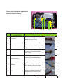
2-9 Disassemble Daughter
Board and Lan Module
Board
1. Unscrew 2 screws (as green circle) to disassemble the Daughter Board.
2. Unscrew 1 screw (as red circle) to disassemble the Lan Module Board.
Daughter Board
Lan Module Board
3. Unscrew 3 hex screws (as yellow circle) from the Main Board Module.
Note: EX612 has not Lan Module Board,so
disassemble Lan Module Board is for
EX615.
EX612/EX615
Confidential
2-
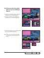
2-10 Disassemble Engine
Module
1. Tear off the black mylar (as green square).
2. Unscrew 4 screws (as yellow circle) to disassemble the Engine Module.
2-11 Disassemble Color
Wheel Module
1. Unscrew 2 screws (as red circle) to disassemble the Color Wheel Module.
2. Unscrew 1 hex screw (as green circle).
3. Unscrew 1 screw (as blue circle) to disassemble the Photo Sensor Board from the Color Wheel Module.
Note: - Avoid touching the glass parts of color wheel.
EX612/EX615
Confidential
2-
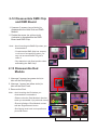
2-12 Disassemble DMD Chip and DMD Board
1. Unscrew 2 screws (as red circle) to disassemble the Heat Sink and DMD Module.
2. Rotate the screw (as yellow circle) clockwise to disassemble the DMD
Board and DMD Chip.
Note: - Avoid touching the DMD Chip when you disassemble it.
-F
ound that the DMD Chip has scrapes
or dirt use of a magnifying glass, you
may use an electrostatic ion gun to
clean it.
- Pay attention to the fixed position when assembling the DMD Chip.
2-13 Disassemble Rod Module
1. Unscrew 2 screws (as green circle) to take off the Rod Spring.
2. Unscrew 1 screw (as yellow circle) to take off the Rod Cover.
3. Remove the Rod.
Note: - Avoid touching the Rod when you disassemble or assemble it.
Rod spring
- Please notice the Rod Module’s direction when you assemble it (as picture A shown).
- Ensure left edge of Rod Module contact with the Engine base’s blocks.
Rod cover
Rod
A
B
- Rod Spring must hook in the position as picture B shown.
EX612/EX615
Confidential
2-10
2-14 Disassemble System Fan Module and Thermal Switch
1. Tear off the black tape (as yellow square).
2. Unscrew 4 screws (as red circle) to disassemble the System Fan Module.
3. Unscrew 1 screw (as blue circle) and unplug 1 connector (as green square) to disassemble the Thermal Switch.
Thermal Switch
4. Unscrew 4 screws (as green circle) to separate Fan and Fan Shielding.
Fan Shielding
EX612/EX615
Confidential
2-11
Note: - Take the Fan Module as the right gesture.
the right gesture
the wrong gesture
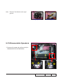
2-15 Disassemble Speakers
1. Unscrew 4 screws (as yellow circle) to disassemble the two Speakers.
EX612/EX615
Confidential
2-12
2. Unscrew 4 screws (as red circle) to separate the Speaker Holder and Speaker.
(Same procedure for the other Speaker)
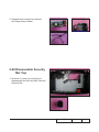
2-16 Disassemble Blower
1. Unscrew 2 screws (as red circle) to disassemble the Blower Module.
2. Separate Blower and Blower Rubber.
EX612/EX615
Confidential
2-13
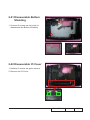
2-17 Disassemble Front IR
Module
1. Unscrew 1 screw (as red circle) to disassemble the Front IR Module.
2. Unfasten 2 tenons (as yellow square) to separate the IR Board and IR Holder.
2-18 Disassemble LVPS Module and Interlock Switch
1. Unscrew 6 screws (as yellow circle).
2. Unplug 1 connector (as blue square).
3. Disassemble the LVPS Module, the AC Inlet Bracket and Mylar.
4. Unscrew 1 screw (as green circle).
AC Inlet Bracket
EX612/EX615
Confidential
2-14
5. Unplug 2 connectors (as green square).
6. Disassemble the Interlock Switch and the cable from the LVPS Module.
Interlock Switch
2-19 Disassemble Lamp Driver Module
1. Unscrew 1 screw (as red circle) to disassemble the Lamp Driver Module.
2. Unplug 3 connectors (as yellow square).
EX612/EX615
Confidential
2-15
3. Separate the Lamp Driver Module and Lamp Driver Holder.
Lamp Driver Holder
2-20 Disassemble Security Bar Cap
1. Unscrew 1 screw (as red circle) to disassemble the Security Bar Cap and Security Bar.
EX612/EX615
Confidential
2-16
2-21 Disassemble Bottom Shielding
1. Unscrew 2 screws (as red cricle) to disassemble the Bottom Shielding.
2-22 Disassemble IO Cover
1. Unfasten 2 tenons (as green square).
2. Remove the IO Cover.
EX612/EX615
Confidential
2-17
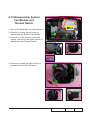
2-23 Rod Adjustment
1. Environment Adjustment
- The distance between the engine and
the screen is 1.95 M.
- This process should be done at a dark
environment (under 10 Lux).
2. Procedure Adjustment
- Change the screen to "white screen".
- Adjust the screws by using the rod
on the engine module to readjust the
image.
("screw 1" should be adjusted first, and then "screw 2". Adjust until the yellowish
or bluish parts disappeared.)
Screw 2
Screw 1
3. Abnormal image inspection
- It should not have any abnormal color
at the rim of the image by estimating
through the eyes.
Note: - To avoid over adjusting the rod.
Z type driver
- After the opreation, please use the glue
to fix the screws.
- Please use Z type driver to adjust Rod screw 1.
EX612/EX615
Confidential
2-18
2-24 Re-write Lamp Usage
Hour
1. Get into Service Mode
- Press "Power", "Left", "Left" and "Menu" buttons sequentially to get into Service Mode.
2. Re-write Projection Hours
- Use "up" or "down" buttons to select "Projection Hours", then use "left" or "right" buttons to re-write the
Projection Hours.
3. Re-write Lamp Hours (Normal)
- Use "up" or "down" buttons to select "Lamp Hours(Normal)", then use "left" or "right" buttons to re-write the
Lamp Hours(Normal).
4. Re-write Lamp Hours (ECO)
- The way of re-write "Lamp Hours (ECO)" is the same as "Lamp Hours(Normal)".
5. Exit Service Mode
- Use "up" or "down" buttons to select "Exit", then press "Enter" to exit the Service Mode.
Note: left key = decrease lamp hour
right key =increase lamp hour
EX612/EX615
Confidential
2-19
Chapter 3
Trobleshooting
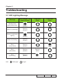
3-1 LED Lighting Message
Message
Standby State
(Input power cord)
Power on (Warming)
Power on and Lamp
lighting
ON/STANDBY LED
(Amber/Green)
Flashing
(Green)
(Green)
Flashing
(Green)
Error
(Lamp failed)
Flashing
(Amber)
Error
(Fan failed)
Flashing
(Amber)
Error
(Over Temp.)
Flashing
(Amber)
Steady light
Lamp LED
(Red)
(Amber)
Power off (Cooling)
Note:
Temp LED
(Red)
(Red)
Flashing
(Red)
(Red)
No light
EX612/EX615 Confidential
3-
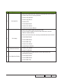
3-2 Main Procedure
No
Symptom
Procedure
- Ensure the Power Cord and AC Power Outlet are securely connected
1
No Power
- Ensure all connectors are securely connected and aren’t broken
- Check LVPS
- Check Lamp Driver
- Check Main Board
- Check LED status
a. Lamp Fail: ON/STANDBY LED (flashes amber);
Lamp LED (lights red)
- Check Lamp
- Check Lamp Driver
- Check Main Board
- Check Color Wheel
- Check Photo Sensor
2
Auto Shut Down
- Check whether Wireless status of OSD Menu is on
(connect VGA1- IN port with VGA source)
b. Over Temp.: �����������������������������������������������
ON/STANDBY�������������������������������������
LED (flashes amber);
Temp LED (lights red)
- Check Thermal Switch
- Check Fan
- Check Main Board
c. Fan Fail: ON/STANDBY��������������������������������������������
������������������������������������������������������
LED (flashes amber);
Temp LED (Flashes red)
- Check Fan
- Check Main Board
EX612/EX615
Confidential
3-
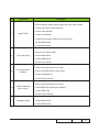
No
Symptom
Procedure
- Ensure all connectors are securely connected and aren’t broken
- Check Lamp Cover, Interrupt Switch
- Check Lamp Module
3
No Light On
- Check Lamp Driver
- Check LVPS
- Check Main Board
- Check Color Wheel
- Check Photo Sensor Board
- Ensure the Signal Cable and Source work
(If you connect multiple sources at the same time, use the
"Source" button switch)
- Ensure all connectors are securely connected and aren’t broken
4
No Image
- Check Main Board
- Check DMD Board
- Check DMD Chip
- Check Color Wheel
- Check Engine Module
5
Mechanical Noise
- Check Color Wheel
- Check Fan Module
- Check whether the Main Board and the DMD Board are
assembled properly
6
Line Bar/Line Defect
- Check Main Board
- Check DMD Board
- Check DMD Chip
EX612/EX615
Confidential
3-
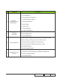
No
Symptom
Procedure
- Do "Reset (All data)" of the OSD Menu
- Ensure that the signal cables and source are work as well
- Check Lamp Driver and waveform
7
Image Flicker
- Check Lamp Module
- Check Color Wheel
- Check Photo Sensor and clean Photo Sensor
- Check DMD Board
- Check Main Board
- Do "Reset (All data)" of the OSD Menu
- Adjust Color Wheel Index
8
Color Abnormal
- Check Main Board
- Check DMD Board
- Check Color Wheel
- Ensure the projection screen without dirt
- Ensure the projection lens is clean
9
Poor Uniformity/
Shadow
- Ensure the Brightness is within spec.
- Check rod alignment
- Check Engine Module
- Ensure the projection screen without dirt
- Ensure the projection lens is clean
10
Dead Pixel/Dust
(Out of spec.)
- Clean DMD Chip and Engine Module
- Check DMD Chip
- Check Engine Module
- Ensure that the signal cables and source work as well
11
Garbage Image
- Check Main Board
- Check DMD Board
EX612/EX615
Confidential
3-
No
Symptom
Procedure
- Remote Controller
a. Check Battery
b. Check Remote Controller
12
Remote
Controller/Control
Panel Failed
c. Check IR Sensor Board
d. Check Main Board
- Control Panel
a. Check FPC
b. Check Keypad
c. Check Main Board
- Do "Reset (All data)" of the OSD Menu
13
Function
Abnormal
- Check Main Board
- Check DMD Board
- Ensure that the signal cables and source are work as well
- Ensure that your Projector is not in “Mute” mode
14
Audio Abnormal
- Check the interior Speakers of the projector
- Check the exterior Speaker that you are using
- Check Main Board
15
Network Fail (for
EX615)
- Check Daughter Board
- Ensure you have set up the right IP address and the
connection is OK (Network green LED should light up)
- Check Lan Module Board
- Check Main Board
EX612/EX615
Confidential
3-
No
Symptom
Procedure
- If you forget the Password, please do the following steps to get
the Universal Password:
(1) When you turn on the projector, the message "Enter
Security Code" appears. Please Input the "Current Security
Code 8642" by Remote Control, then press "Enter".
(2) Press "Menu" button, select "Setup", "Change Password",
then press "Enter" button. The message "Enter Security
Code" appears again, repeat step (1).
(3) The message "Enter New Security Code" appears. Input a
4-digits code (letters and/or numbers) that you define.
(4) To confirm, key in the password again. The "Security Code
change successfully" appear on the screen.
16
Forgetting
Password
(Administrator
Password)
(1)
(2)
(3)
EX612/EX615
Confidential
3-
Chapter 4
Function Test & Alignment Procedure
4-1 Test Equipment Needed
- IBM PC with XGA resolution
- DVD player with Multi-system, equipped “Component”, “S-Video”,“Composite” and
"HDMI".
- HDTV Source (720P,1080P,1080i)
- Minolta CL-100
- Quantum Data 802B or CHROMA2327 (Color Video Signal & Pattern Generator)
4-2 Service Mode
- EX612/EX615 have two kinds of Service Mode,use different ways to get into each Service
Mode:
1. Turn on the projector
2. (1) Press "Power", "Left", "Left" and "Menu" buttons sequentially to get into Service Mode 1.
(2) Press "Power", "Up", "Down" and "Menu" button sequentially to get into Service Mode 2.
(3) Select "Exit" to leave the Service Mode after confirming the configuration.
4-3 OSD Reset
- After final QC step, we have to erase all saved change again and restore the OSD default setting. The following actions will allow you to erase all end-users' settings and restore the default setting:
1. Please get into OSD menu.
2. Execute "Reset" function.
EX612/EX615
Confidential
4-
4-4 Test Condition
- Circumstance brightness: Dark room less than 10.0 lux.
- Inspection distance: 1.8 m~2.5 m functional inspection.
- Screen size: 60 inches diagonal.
- After repairing each unit, a Run-in test is necessary (refer to the below table).
Symptom
Normal repair
NFF
Auto shutdown
Run-in Time
2 hours
4 hours
6 hours
- Get into Burn-In Mode
* Cycle setting is based on the defect symptoms. ie: If it is NFF, the run-in time is 4 hours. You have
to set the lamp on for 50 min. and lamp off for 10 min for 4 cycles.
Press Power > Left > Left > Menu to get into service mode 1
Choose Burn-In Test > enter
Lamp On (Mins)
Press right key to adjust the time (50)
Lamp Off (Mins)
Press right key to adjust the time (10)
Burn in cycle
Press right key to adjust the cycle
After setting up the time, choose ''Enter to Burn-In'' and press Enter button
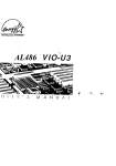
Screen Defects (While replacing DMD Chip, DMD Board and Main Board)
12.5 cm
Zone B
Frame
Zone C
12.5 cm
< Figure: Zone A, Zone B & Frame(as green line) Definition, Active area=Zone A+ Zone B >
EX612/EX615
Confidential
4-
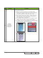
4-5 Defect specification table
For EX612/EX615
Order
Symptom
Pattern
Criteria
1
Bright pixel ( dots)
Any pattern
A+B=0
2
Dark pixel(dots)
Any pattern
A+B≤4
3
Unstable pixel (dots)
Any pattern
A+B=0
4
Adjacent dark pixel (dots)
Any pattern
A+B=0
5
Dark blemish (Dirty)
Blue 60 pattern
A+B≤4
(diameter <1 inch)
6
Bright blemish (Dirty)
Gray 10 pattern
A+B≤4
(diameter <1 inch)
7
Bright dots on frame
Any pattern
≤1
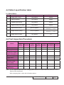
4-6 Test Inspection Procedure
Change parts
Update
Main
Board
Firmware
Version Update
v
v
Color Wheel Index
v
ADC
Calibration (RGB/
Video Calibration)
v
Color
Wheel
Lamp
Module
Engine
Module
Blower
v
v
Reset lamp hour
v
OSD Reset
v
EDID
v
Re-write Lamp
Hour Usage
v
v
Rod adjustment
Factory
RPM Save
Lan Module
(for EX615)
v
v
v
Note: - If Color appears abnormal after changing Main Board/Color Wheel Module, please do Color Wheel index adjustment.
- After changing parts, check the information above.
EX612/EX615
Confidential
4-
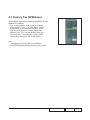
4-7 Factory Fan RPM Reset
After replace main board, blower or upgrade FW, you
need to do as below:
1.Turn on the projector, after about 30 seconds,
press“Power”, “Left”, “Left” and “Menu” button
sequentially to get into service mode1, press
right key to change the “Factory RPM Save”
status to “On”.The “Current Blower RPM” will
be saved after 3 seconds and “Factory RPM
Save”status change to “Off” automatically.
Note:
If the Blower Factory RPM is not between
4292~5454,please change blower or main board.
EX612/EX615
Confidential
4-
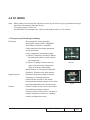
4-8 PC MODE
Note: - When getting into function test, adjust the zoom ring and focus ring to guarantee the image maximum and clearest, then start to test.
- Test signal: analog 1024 x 768
- we take EX615 for example here, others model please refer to 4-5 for details.
1. Frequency and tracking boundary
Procedure
- Test equipment: video generator
- Test signal: analog 1024 x 768@60Hz
- Test Pattern: General-1 or Master
- Check and see if the image sharpness
is well performed.
- If not, re-adjust by the following steps:
(1) Select "Frequency" function to adjust
the total pixel number of pixel clock in
one line period.
(2) Select "Tracking" function and use
right or left arrow key to adjust the
value to minimize video flicker.
- Adjust Resync or Frequency/Tracking/H.
Position/V. Position to the inner screen.
Inspection item
- Eliminate visual wavy noise by Resync,
Frequency or Tracking selection.
- Check if there is noise on the screen.
- Horizontal and vertical position of the video
should be adjustable to the screen frame.
Criteria
- If there is noise on the screen, the product
General-1
Master
is considered as failure product.
- If there is noise on the screen, use auto or
manual “frequency” function or “tracking”
function to adjust the screen.
EX612/EX615
Confidential
4-
- The PC mode functionally sure be workable
include support format with frequency and auto
detected functional will be workable.
2.Bright pixel
Procedure - Test equipment: video generator.
Inspection item
Criteria
- Test signal: analog 1024x768@60Hz.
- Test Pattern: Gray 10
- Bright pixel check.
- Bright pixel is unacceptable under gray 10 pattern.
Please refer to the figure in 4-4 Test Condition
for Frame and Active area.
Note: The defect criteria follows TI specification.
Gray 10
3. Dark pixel
Procedure - Test equipment: video generator.
- Test signal: analog 1024x768@60Hz.
- Test Pattern: White pattern
Inspection item
- Dark pixels check.
- White pattern
- Adjacent dark pixel.
Criteria
- The number of the dead pixels should be less or
equal to 4 pixels.
White pattern
- Adjacent pixel with each other is unacceptable.
Note: The defect criteria follows TI specification.
EX612/EX615
Confidential
4-
4. Bright Blemish
Procedure
Inspection item
Criteria
5. Dark Blemish
Procedure
Inspection item
Criteria
- Test equipment: video generator
- Test signal: 1024x768 @60Hz
- Test Pattern: Gray 10
- Bright blemish check
- The bright blemish should be less or
equal to 4 under gray 10 pattern.
- Ref. Defect specification table
- Test equipment: video generator
- Test signal: 1024x768 @60Hz
- Test Pattern: Blue 60
- Dark blemish check
- The dark blemish should be less or
equal to 4 under blue 60 pattern.
- Ref. Defect specification table
Gray 10
Blue 60
6. Focus test
Procedure
- Test equipment: video generator.
- Test signal: analog 1024 x 768@60Hz
- Test Pattern: full screen or MEME Sony
Inspection item
Criteria
- Focus check
-From screen 2.38 Mvia visual to check the
focus, look at the entire screen, focus shall be
clear, crisp, and sharp over the entire surface
of the display pattern.(Blur word on one of the
corner after adjustment is acceptable. However,
the word should at least be recognizable.)
EX612/EX615
Full screen
Confidential
4-
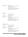
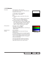
7. Color performance
Procedure
- Test equipment: video generator.
- Test signal: 720p, 1080i, 1080p
- Test Pattern: Master, 64 gray RGBW or
SMPTE bar
* Please refer to 4-2 to get into service mode 1.
Use 720p & 1080p signal, master pattern to do
HDTV test. Color cannot discolor to purple and
blue.
Inspection item
- Check if each color level is well-functioned.
- Color saturation
Criteria
- Screen appears normal. It should not have any
abnormal condition, such as lines appear on the
screen and so on.
- Color appears normal.
- It is unacceptable to have few lines flashing.
- RGBW should all appear normal on the screen
and sort from R-G-B-W.
- Color levels should be sufficient and normal.
(The unidentified color levels on both left and
right sides should not over 4 color levels.)
- Gray level should not have abnormal color or
heavy lines.
- If color appears abnormal, please get into service mode 1 to do color wheel index adjustment.
Master
64 gray RGBW
SMPTE BAR
4-9 Video Performance
1. CVBS
Procedure - Test equipment: DVD player
- Test signal: CVBS
Inspection item
- Video performance test
Motion video
EX612/EX615
Confidential
4-
Inspection Distance - 1.8 M ~2.5 M
Criteria
- Check any abnormal color, line distortion or any
noise on the screen.
- Check the sound from speakers.
- Check whether "freeze" and "mute" are normal.
- Press "V Keystone" on remote controller, check whether keystone function is normal.
2. S-Video
Procedure
- Test equipment: DVD player
- Test signal: S-Video
Inspection item
- Video performance test
Inspection Distance - 1.8 M ~2.5 M
Criteria
- Check any abnormal color, line distortion or any
noise on the screen.
- Check the sound from speakers.
- Check whether "freeze" and "mute" are normal.
- Press "V Keystone" on remote controller, check whether keystone function is normal.
3. HDTV/Component
Procedure - Test equipment:DVD player
- Test signal:Ycbcr/YPbPr
Inspection item
- HDTV performance test
InspectionDistance - 1.8 M ~2.5 M
Criteria
- Check any abnormal color, line distortion or any
noise on the screen.
- Check the sound from speakers.
- Check whether "freeze" and "mute" are normal.
- Press "V Keystone" on remote controller, check whether keystone function is normal.
EX612/EX615
Confidential
4-
4. HDMI Test (not for EX612)
Procedure - Test equipment: DVD Player with HDMI output.
- Test signal: 720p, 1080p, 1080i
Inspection item
- HDMI performance test.
Inspection Distance - 1.8 M ~2.5 M.
Criteria - Ensure the image is well performed and the color can not discolor.
- Check whether "mute" is normal.
5. Audio Test
Procedure
- Test equipment: DVD Player
- Test signal: CVBS
Inspection item - Audio performance test
Inspection Distance - 1.8 M ~2.5 M
Criteria
- Check the sound from speakers
- Plug Audio cable into Audio in 1 port, check whether "Volume" is normal.
- Plug Audio cable into Audio Out port, check whether the outboard speaker’s “Volume” is normal.
- Adjust the volume to "5→ 10" by using the
remote controller.
- Check the sound from speakers.
- Check whether the "mute" is normal.
Note: EX615 has 3 Audio.
In ports for different input signals. To test each
Audio In port, make sure input its correspondent signal.
EX612/EX615
Confidential
4-10
6. 3D Test
Procedure
- Test equipment: 1. DVD Player & HQFS format CD
or 2. PC with 3D Graphic card
- Test signal: 1280X720@120Hz (HQFS format CD)
Inspection item
- 3D test
Inspection Distance
- < 6M
Criteria
- The image should not appear noise, flicker,
shadow, shocking, abnormal color.
4-10 ADC Calibration
1. Video Calibration
�����������
Procedure - Test equipment: video generator
- Once Main Board is changed, video calibration
should be done as well.
(1) Test signal: 480i
SMPTE BAR
(2) Test Pattern: SMPTE BAR
- Note
(1) Calibration pattern should be in full screen mode.
(2) Please refer to 4-2 Guide to get into service
mode 1 and choose "ADC calibration".
Check pattern
(3) Choose and get into "Video Calibration", press
"Enter" button to execute "Video Calibration". When the message "Success" appears, it means "Video Calibration" is
OK. Choose "Menu" or "Exit" to leave service mode 1.
Master
- Test signal: 576p, 720p, 1080i
- Test pattern: Master
* After finishing Video adjustment, check Master pattern.
Inspection item
- Color saturation
Criteria
- There should not have any lack of SMPTE BAR.
- The screen appears normal, it shouldn’t appear any abnormal condition, such as lines and so on. - It is unacceptable that the color appears abnormal and flashing.
EX612/EX615
Confidential
4-11
2. RGB Calibration
�����������
Procedure - Test equipment: video generator
- Once Main Board is changed, RGB calibration
should be done as well.
(1) Test signal: 1024 x 768@60Hz
(2) Test Pattern: White/Black
- Note
(1) C
alibration pattern should be in full screen
mode.
(2) P
lease refer to 4-2 Guide to get into service
mode 1 and choose "RGB calibration".
(3) C
hoose and get into "Video Calibration",
press "Enter" button to execute "RGB Calibration". When the message "Success" appears,
it means "RGB Calibration" is OK. Choose
"Menu" or "Exit" to leave service mode 1.
Check pattern
- Test signal: 1024 x 768@60Hz
- Test pattern: 64 grey RGBW
White/Black
* After finishing RGB adjustment, check 64 gray RGBW pattern.
Inspection item
- Color saturation
Criteria
- There should not have any lack of 64 gray
RGBW pattern.
- The screen appears normal, it shouldn’t appear any abnormal condition, such as lines and so on. - The color should appear normal and sort in right order, it is unacceptable that the color appears abnormal and flashing.
- Color levels should be sufficient and normal.
(the unidentified color levels on both left and
right sides should not over 8 color levels.)
EX612/EX615
64 gray RGBW
Confidential
4-12
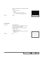
4-11 Optical Performance Measure
Inspection Condition
- Environment luminance: 10.0 Lux
- Product must be warmed up for 5 minutes
- Distances from the screen: 1.95 M
- Screen Size: 60 inches diagonal
1. Test equipment
Procedure - Press "Power→ Left→ Left→ Menu" to get into service mode 1.
- Select "Spoke Test"
2. Brightness
Procedure - Full white pattern
- Use CL100 to measure brightness values of P1~P9.
- Follow the brightness formula to calculate
brightness values.
☼ Brightness Formula
Criteria
Avg. (P1~P9)*1.1m2
• 1400 ANSI lumen
3. Full On/Full Off Contrast
Procedure
- Full white pattern & Full black pattern
- Use CL100 to measure brightness values of full
white pattern P5 & full black pattern B5
EX612/EX615
Confidential
4-13
- Follow Contrast formula to calculate contrast
values.
☼ Contrast Formula
P5/B5
Note: P
5=center of white image
Criteria
B5 = the center of black image.
• 1600:1
Full black pattern
4. Uniformity
Procedure
- Full white pattern
- Use CL100 to measure brightness values of
P1~P9 (see image: Full white).
- Follow the Uniformity formula to calculate
average values.
Criteria
☼ Uniformity Formula
JBMA Uniformity = Avg. (P1, P3, P7, P9)/
P5X100%
• 70%
Full white pattern
EX612/EX615
Confidential
4-14
4-12 Network Function Test
For EX615
1. Write Down Projector IP
(1) Turn on the Projector, then press "Menu" button to get into OSD Mode.
- Use "right" button to select "SETUP".
- Use "down" button to remove the light mark to "RS232", then press "Enter" button to select "Network", press "Enter" button.
(2) Select "Network", press "Enter" button.
(3) Remove the light mark to "DHCP", then press "Enter" button to select "Off", press "Enter" button.
- The IP address will be shown on screen.
- Write down the IP address: 192.168.0.100.
- Ensure the IP address, Subnet Mask, Gateway and DNS are right as the the picture shown.
EX612/EX615
Confidential
4-15
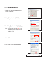
2. Network Setting
(1) Open the "Local area connection", choose "properties". (2) Select "Internet protocol (TCP/IP)", then click
"Properties".
(3) Modify the IP address to 192.168.0.101, and modify Subnet mask to 255.255.255.0.
Note: - The HOST ID (192.168.0.XXX) of PC
IP address must be different from the projector IP address written down in
step 1 of 4-10.
(4) Click "OK".
(5) Click "Close" to quit the setting screen.
EX612/EX615
Confidential
4-16
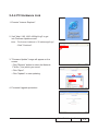
3. Read Projector Information
(1) Connect the PC and the Projector with LAN Cable.
(2) Execute "Internet Explorer".
(3) Visit the IP address: "http://192.168.0.100/".
- Key in "User Name: Administrator" and "Password: administrator", click "Login" to get into Projector Web Server.
(4) Projector information will be shown on the screen.
- Please check whether each item's function is OK.
EX612/EX615
Confidential
4-17
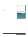
4-12 Others
1. Function Inspection
Keypad button
- All keypad buttons must operate smoothly.
General
- All OSD functions must be checked for functionality. When OSD
menu is displayed, there shall be no visible peaking, ringing,
streaking, or smearing artifacts on the screen.
Factory Default
- The factory settings (with appropriate centering, size, geometry
distortion, etc.) shall be displayed upon “Recall” is selected from
OSD.
Display Size
- All preset modes shall expand to full screen size using OSD
Horizontal and Vertical Size controls.
Display Data Channel (DDC) - The purpose of the DDC test is to verify the DDC1/DDC2B
operation of the projector and to verify Plug & Play function.
Acoustic
-H
igh pitch sound from cooling fan and color wheel is
unacceptable.
2. Check points for exterior and print pattern
Check item
Text & Pattern
Exterior
Focus Ring&Zoom Ring
Logo
Check point
Missing letters & pattern or blurry prints are
unacceptable.
Dirt, scrape, water ripples and uneven color are
unacceptable.
Focus ring&Zoom ring is functioning smoothly.
Missing logo, missing prints and blurry prints are
unacceptable
Screw
All screws sure be fixed and in right type.
Pedestal
Well-functioned
Lamp Cover
It should be locked in the correct place.
Plastic Parts
All plastic parts can not be broken and damaged.
All safety and warning labels should be visible,
Safety or warning label
including all contents.
All interface connectors should be complete and
Connector
workable.
EX612/EX615
Confidential
4-18
Chapter 5
Firmware Upgrade
Section 1: System Firmware Upgrade
5-1-1 Equipment Needed
Software: (DDP 2430-USB);
- DLP Composer Lite 9.2
- Firmware (*.img)
- Library file (Library 9.2)
Hardware:
- Projector
- Power Cord: 42.50115G001
- Mini USB Cable: 42.00286G101
- PC or Laptop
Note: The FW upgrade procedure for EX612/EX615 is the same,we take EX615 as an example
here.
EX612/EX615 Confidential
5-
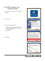
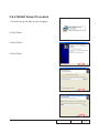
5-1-2 DLP Composer Lite
Setup Procedure
1. Choose "DLP Composer Lite V9.2 Setup"
Program.
2. Click "Next".
3. Read "License Agreement".
-C
hoose "I accept and agree to be bound
by all the terms and conditions of this
License Agreement".
- Click "Next".
4. Click "Next".
EX612/EX615 Confidential
5-
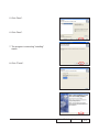
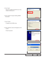
5. Click "Next".
6. Click "Next".
7. The program is executing "installing" status.
8. Click "Finish".
EX612/EX615 Confidential
5-
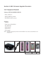
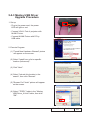
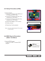
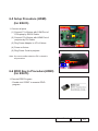
5-1-3 Setup Procedure
1. Set up
- Hold on "MENU" and "POWER" buttons and plug in the power cord.
- The ON/STANDBY LED will be flashing green.
- Release "MENU" and "POWER" buttons.
-C
onnect projector with USB cable.
Note: - The system fan and the lamp will not
operate.
USB port
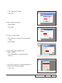
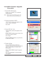
5-1-4 USB Driver Upgrade Procedure
(2)
1. Execute Program
(1) Connect projector with PC by USB cable.
(2) "Found New Hardware Wiszard" picture will appear on the screen.
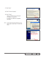
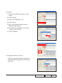
(3)
(4)
(3) Select "Install the software automatically (Recommended)".
(4) Click "Next".
(5) Searching picture, please wait for several seconds.
(6) Click "Finish", then the USB driver has been installed successfully.
EX612/EX615 Confidential
5-
Note: - If you have installed the USB driver, there is no need to perform this action.
(6)
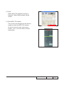
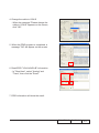
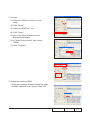
5-1-5 Firmware Upgrade Procedure
1. Execute the "DLP ComposerTM Lite 9.2" file.
2. Click "Edit" and "Perferences".
3. Click "Library".
-C
lick the "Browse" and navigate to the directory
where you put the DLP Composer installation files
in.
EX612/EX615 Confidential
5-
- Click "Library 9.2" folder.
- Click "OK".
4. Click "Communications".
- Select "USB".
- Click "OK".
5. Choose "Flash Loader".
-C
lick "Browse" to search the firmware file
(*.img).
- Click "Open".
6. Select "Skip Boot Loader Area".
(select "32KB").
- Click "Reset Bus" to erase the flash memory.
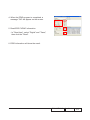
7. If the FW is ready, click "Start Download" to
execute the firmware upgrade.
- Click "Yes".
EX612/EX615 Confidential
5-
8. Proceeding Picture.
9. It takes about several minutes, the firmware upgrade process is finished, "Download completed" will appear on the screen.
- The projector will automatically turn on.
-U
nplug USB cable.
10. Check FW version. - Get into the service mode to check the firmware version.
( To get into service mode, please press
"Power", "Left", "Left" and "Menu" buttons
sequentially.)
EX612/EX615 Confidential
5-
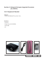
Section 2: 8051 Firmware Upgrade Procedure
5-2-1 Equipment Needed
Software: (DDP 2430-USB/EX612/EX615)
- Setup _NLINK_en
- Manley USB Driver_NLINK
- EX612/EX615_8051_xxx.hex
Hardware:
- Projector
- Power Cord: 42.50115G001
- Mini USB Cable
- NLINK Cable 2
- NLINK Fixture
- PC or Laptop
Note: - The 8051 FW upgrade procedure for EX615/EX612 is the same, we take EX615 as an
example here.
EX612/EX615 Confidential
5-
5-2-2 NLINK Setup Procedure
1. Choose "setup_NLINK_en.exe" program.
2. Click "Next".
3. Click "Next".
4. Click "Next".
EX612/EX615 Confidential
5-
5. Click "Next".
- Select the additional task that you may create a desktop icon.
6. Click "Install" to begin installing NLINK Procedure.
7. Click "Finish".
- Complete the NLINK setup.
8. "MCU Choose" picture will appear on the screen.
- Close the picture.
EX612/EX615 Confidential
5-10
5-2-3 Manley USB Driver Upgrade Procedure
1. Set up
- Plug in the power cord, the power LED will light on red.
VGA-1 Port
- Connect VGA-1 Port of projector with NLINK Fixture.
- Connect NLINK Fixture with PC by USB cable.
(1)
2. Execute Program
(1) "Found New Hardware Wiszard" picture will appear on the screen.
(2)
(3)
(2) Select "Install from a list or specific
location (Advanced)".
(3) Click "Next".
(4)
(4) Select "Include this location in the search", then click "Browse".
(5) "Browse For Folder" picture will appear on the screen.
(5)
(6) Select "TPRP1" folder in the "Manley USB Driver_N-Link" folder, then click "OK".
(6)
EX612/EX615 Confidential
5-11
(7) Click "Next".
(8) Click "Continue Anyway".
(9) Click "Finish".
- "Manley TPRP1-Protocol Emulator" will appear on the picture.
(7)
- Complete the USB Driver Upgrade Procedure.
Note: - If "Found New Hardware Wiszard" picture appear again, repeat step 2 to install USB Drivier.
(8)
(9)
EX612/EX615 Confidential
5-12
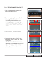
5-2-4 8051 Firmware Upgrade Procedure
1. Execute 8051 FW Program
- Double click "NLINK V1.2" to execute
NLINK program.
Note: - When we execute NLINK program, the power LED and Fixture LED flash red.
2. Choose the right type of MCU
- "MCU Choose" picture will appear on the screen, select "W79E804".
- Click "OK".
3. Choose 8051 file (*.hex)
- "Manley Nlink" picture will appear on the screen.
- Ensure "MCU" is the one you chose in the last step (as green square).
- Click "Open".
- Select the 8051 file where you put the file in, then click "Open".
4. Program settings
- Ensure NLlNK Fixture and PC are securely connected: the indicator lights on green, and the state is "Connect" (as blue square).
- Select "4MHz-20MHz Crystal" (as green square).
- Click "Erase/Write(W)" to execute 8051 FW upgrade.
EX612/EX615 Confidential
5-13
5. Finish
- When 8051 FW upgrade process is finished, "Write Chip success" will be shown.
6. Check 8051 FW version
- Turn on the unit and get into the service mode to check the 8051 FW version.
(To get into service mode, please press "Power", "Left", "Left" and "Menu" buttons sequentially.)
EX612/EX615 Confidential
5-14
Section 3: Network Firmware Upgrade Procedure
(for EX615)
5-3-1 Equipment Needed
Software:
- EX615_LAN Module FW_xxx.bin (*.bin)
Hardware:
- Projector
- Power Cord: 42.50115G001
- LAN Cable
- PC
EX612/EX615 Confidential
5-15
5-3-2 Write Down Projector IP
1. Plug in power cord to the projector and plug in LAN cable to the PC.
2. Turn on the projector, then press "Menu" button to get into OSD menu.
- Use "right" button to select "SETUP".
2
- Use "down" button to remove the light mark to "RS232", then press "Enter" button to select "Network", press "Enter" button.
3. Select "Network", press "Enter" button.
3
4. Remove the light mark to "DHCP", then press "Enter" button to select "Off", press "Enter" button.
- The IP address will be shown on screen.
- Write down the IP address: 192.168.0.100.
4
- Ensure the IP address, Subnet Mask, Gateway and DNS are right as the the picture 4 shown.
EX612/EX615 Confidential
5-16
5-3-3 Network Setting
1. Double click the "Local area connection", choose "Properties". 2. Select "Internet protocol (TCP/IP)", then click "Properties".
3. Modify the IP address to 192.168.0.101, and modify Subnet mask to 255.255.255.0.
Note: - The HOST ID (192.168.0.XXX) of PC IP address must be different from the projector IP address written down in step 4 of 5-3-2.
4. Click "OK".
5. Click "Close" to quit the setting screen.
EX612/EX615 Confidential
5-17
5-3-4 PC Hardware Link
1. Execute "Internet Explorer".
2. Visit "http:// 192.168.0.100/tgi/fu.tgi" to get into Firmware Update screen.
Note: - The format of address is "IP address/tgi/fu.tgi".
- Click "Continue".
3. "Firmware Update" image will appear on the screen.
- Click "Browse" button to select the Network FW file (*.bin) which you saved.
- Click "Open".
- Click "Update" to start updating.
4. Firmware Upgrade procedure.
EX612/EX615 Confidential
5-18
5. Click "Re Login".
6. Firmware upgrade procedure completes.
- The projector Network FW version will appear.
EX612/EX615 Confidential
5-19
Chapter 6
EDID Upgrade
6-1 EDID Introduction
Extended Display Identification Data is a VESA standard data format that contains basic
information about a display device and its capabilities, including vendor information,
maximum image size, color characteristics, factory pre-set timings, frequency range limits,
and character strings for the monitor name and serial number.
The information is stored in the display and is used to communicate with the system
through a Display Data Channel (DDC), which sites between the display device and the
PC graphics adapter. The system uses this information for configuration purposes, so the
monitor and system can work together.
Note: - If a display device has digital input ports, like DVI or HDMI, but without EDID in its Main Board, the display device will show no image while the input source is digital signal.
- The EDID Upgrade procedure for EX615/EX612 is the same, we take EX615 as an example
here.
EX612/EX615
Confidential
6-
6-2 Equipment Needed
Software
- EDID Program
- EDID File (*.ini)
Hardware
- Projector
- Power Cord for Projector (42.53506G002)
- VGA Cable (42.87305G102)
- HDMI(M) to DVI(F) Adapter (42.82B13G001)
- DVI Cable (42.83N06G001)
- Generic Fixture (80.00001.001) for EDID Key-in (Fixture: JP3 must be closed)
- RS-232 9 Pin Cable (pin to pin, F-M) (42.83C07G001)
- Power Adapter (47.57803G001)
- Monitor
- PC
EX612/EX615
Confidential
6-
6-3 Setup Procedure (VGA)
RS232 Cable
1. Connect all ports
(1) Connect P1 of fixture with COM Port of PC/Laptop by RS232 Cable.
(2) Connect P3 of fixture with VGA-1 Port of projector by VGA Cable 1.
(3) Connect P4 of fixture with VGA-2 Port of projector by VGA Cable 2.
Adapter
P1
P3
VGA Cable 1
P4
JP1
JP3
VGA Cable 2
(4) Plug Power Adapter to JP1 of fixture.
(5) Power on fixture.
(6) Plug Power Cord to projector.
VGA-1 Port
Note: -You must confirm that the JP3 is closed
in all procedure.
VGA-2 Port
Power Port
6-4 EDID Key-In Procedure (VGA-1 & VGA-2)
1. Execute EDID Program
- Double click "EDID" to execute EDID program.
EX612/EX615 Confidential
6-
2. Process
(1) Select the COM Port which you are using.
(2)
(2) Click "Model".
(3) Select the EDID file (*.ini).
(4) Click "Open".
(1)
(5) Key in the Serial Number into the Barcode blank space.
(6) In "Write Source Select" item, select
"VGA-A" and "VGA-B".
(7) Click "Program".
(3)
(4)
(5)
(7)
(6)
3. Change the cable to VGA-A
- When the message "Please change the cable to VGA-A" appears on the screen, click "OK".
EX612/EX615
Confidential
6-
4. Change the cable to VGA-B
- When the message "Please change the cable to VGA-B" appears on the screen, click "OK".
5. When the EDID program is completed, a message "OK" will appear on the screen.
6. Read EDID "VGA-A&VGA-B" information
- In "Read item", select "Analog" and "Trans", then click the "Read".
7. EDID information will show the result.
EX612/EX615 Confidential
6-
6-5 Setup Procedure (HDMI) (for EX615)
RS232 Cable
1. Connect all ports
Adapter
P1
(1) Connect P1 of fixture with COM Port of PC/Laptop by RS232 Cable.
JP1
JP3
(2) Connect P5 of fixture with HDMI Port of projector by DVI Cable.
P5
(3) Plug Power Adapter to JP1 of fixture.
DVIDVI
Cable
Cable
(4) Power on fixture.
(5) Plug Power Cord to projector.
Note: You must confirm that the JP3 is closed in all procedure.
HDMI Port
Power Port
6-6 EDID Key-In Procedure(HDMI)
(for EX615)
1. Execute EDID Program
- Double click "EDID" to execute EDID program.
EX612/EX615
Confidential
6-
2. Process
(1) Select the COM Port which you are using.
(2)
(2) Click "Model".
(3) Select the EDID file (*.ini).
(1)
(4) Click "Open".
(5) Key in the Serial Number into the Barcode blank space.
(6) In "Write Source Select" item, select "HDMI".
(7) Click "Program".
(3)
(4)
(5)
(7)
(6)
3. Change the cable to HDMI
- When the message "Please change the cable to HDMI" appears on the screen, click "OK".
EX612/EX615 Confidential
6-
4. When the EDID program is completed, a message "OK" will appear on the screen.
5. Read EDID "HDMI" information
- In "Read item", select "Digital" and "Trans", then click the "Read".
6. EDID information will show the result.
EX612/EX615
Confidential
6-
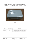
Appendix A (Exploded Image)
Note: This chapter is only designed to show the exploded image of the projector. For updated part numbers, please refer to RSPL report.
D.C.
EX612/EX615
Confidential
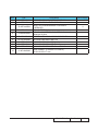
Item
P/N
Description
1
2
3
70.8EF11G001
70.8EF01G001
70.8EF08G001
4
70.8EF06G001
5
51.8EF02G001
70.8EF45GR01
51.8EG03G011
61.00018G002
SP.8EG01GC01
41.83M06G001
85.1A123G050
85.00823G080
61.8EG03G001
85.0A122G030
85.1A323G080
85.1A526G060
70.8EG17G001
85.1A123G060
EX612 ASSY BOTTOM HOUSING MODULE
ASSY OPTICAL ENGINE MODULE EX612
MAIN BOARD ASSEMBLY EX612
TOP COVER AND ZOOM RINGASSYEMBLY
EX612
FOCUS RING EX612 (FOR YM09)
ASSY LAMP COVER BLACK EX615 (SERVICE)
LAMP COVER BLACK EX615
LOCK SCREW PAN MECH M3*8.5-3.5 BLACK
LAMP MODULE FOR PROJECTOR EX615/EX612
EMI TAPE W30*L70mm
SCREW PAN MECH M3*5 Ni
HEX SCREW M3*H8*L5.3,BRASS
TOP SHIELDING HD20
SCREW DOUBLE FLAT MECH M2*3Ni
SCREW PAN MECH M3*8 BLACK “GREEN”
SCREW PAN MECH M2.6*6 Ni NYLOK
ASSY 8525 FAN SHIELDING MODULE HD20
SCREW PAN MECH M3*6 NI
6
7
8
9
10
11
12
13
14
15
16
17
EX612/EX615
Parts Supply
Confidential
V
V
II
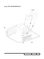
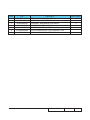
Assy TOP COVER MODULE
7
6
4
5
1
3
2
EX612/EX615
Confidential
III
Item
P/N
1
2
3
4
5
6
7
75.8EF01G002
51.8EG14G011
80.8EF03G001
85.1A123G050
85.1A123G050
85.41BA6G060
51.8EG11G001
Description
Parts Supply
TOP COVER ASSEMBLY EX615
KEYPAD PLATE ENTER EX612
PCBA KEY PAD BOARD FOR EX615
SCREW PAN MECH M3*5 Ni
SCREW PAN MECH M3*5 Ni
FLAT SCERW M2.6*6 Flat Thickness1.1mm
ZOOM RING DUST COVER HD20
EX612/EX615
V
V
Confidential
IV
ASSY BOTTOM COVER MODULE
5
4
18
3
2
12
13
9
7
11
16
6
8
10
1
14
15
EX612/EX615
Confidential
Item
P/N
70.8EF37GR01
1
51.8EG01G011
70.8EF38GR01
2
75.8BW01G002
3
75.8AA04G001
4
51.89W18G001
5
6
7
85.WA126G060
61.88T19G001
75.8CT01G001
8
85.1C224G051
9
10
11
12
13
14
15
16
61.87340G001
51.8EG20G001
70.8EG14G001
70.8EF10G001
85.WA123G060
51.8EG05G001
80.87Z04G001
85.1F123G060
17
42.00451G011
18
85.1F123G060
19
42.81G01G001
20
21
22
51.8EG27G001
51.8EF06G001
51.8EG31G001
Description
Parts Supply
ASSY BOTTOM COVER MODULE FOR EX615
(SERVICE)
BOTTOM COVER MN3600H BLACK EX612
ASSY OSRAM LAMP DRIVER 230W FOR EX615
(SERVICE)
ASSY OSRAM LAMP DRIVER O3 MID 230W
(Gen5_Panyu+E20.8)
BUY ASSY INTERLOCK SWITCH 1409X
LIMIT SWITCH HOLDER PC MN3600H BLACK
TDP-SP1
SCREW PAN HEAD TAP M2.6*6
AC INLET BRACKET FOR X1160E
ASSY MATRITEK 230W LVPS FOR HORUS
SCREW PAN MECH M4*5 COLOR W/TOOTH
WASHER Cr3+
STAND OFF M3*4L D8.0 2100MP
230W LVPS MYLAR PC T=0.43 HD20
ASSY 4520 BLOWER MODULE HD20
EX612 2W SPEAKER HOLDER ASSY
SCREW PAN TAP M3*6 Ni
IR FRONT BOTTOM HOLDER MN3600H BLACK
PCBA IR SENSOR BD HD80
SCREW PAN MECH W/SF M3*6 Ni GREEN
W.A. 16P 90mm LVPS TO MAIN BD UL1007
P1266
SCREW PAN MECH W/SF M3*6 Ni GREEN
CABLE W.A. 2P #20 160mm LAPS TO BALLAST
PD120
REAR SPEAK MYLAR HD20
AIR STOP MYLAR EX615
FRON LEFT LIGHT LEAK MYLAR HD20
EX612/EX615
Confidential
V
V
V
VI
ASSY MAIN BOARD AND IO BOARD MODULE
8
9
10
Item
P/N
1
70.8EF09G001
70.8EF43GR01
2
3
4
5
6
7
8
9
10
80.8EF01G003
80.8EF07G001
61.00080G001
85.1A122G040
86.0A123G024
85.1A123G050
61.83N19G001
80.8EF06G002
85.1A123G050
Description
Parts Supply
IO BOARD ASSEMBLE EX612
ASSY PCBA MAIN BOARD FOR EX615
(SERVICE)
PCBA MAIN BD FOR EX615
PCBA LAN MODULE BD FOR EX615
STAND OFF H=6.0 M2/M3*L6 Sn EP910
SCREW PAN MECH M2*4 Ni
HEX NUT M3*5.5*0.5P L2.4 Ni
SCREW PAN MECH M3*5 Ni
HEX SPACER M3 H=17mm L=5mm AL PD726
PCBA DAUGHTER BOARD FOR EX615
SCREW PAN MECH M3*5 Ni
EX612/EX615
Confidential
V
V
V
V
VII
ASSY MAIN BOARD MODULE
EX612/EX615
Confidential
VIII
Item
P/N
Description
1
2
70.8EF26G001
61.8EG02G011
MAIN BOARD IO BOARD ASSY EX612
MAIN BOARD SHIELDING EX612
ASSY IO COVER MODULE FOR EX615
(SERVICE)
IO COVER EX612
ADUIO I/O PORT EMI GASKET W13*H1*L13mm
diameter 6.5mm
SCREW HEX I/O #4-40 H4*L8 NI NYLOK
SCREW PAN MECH M3*5 Ni
MAIN BOARD MYLAR EX542
MAIN BOARD SPONGE EX615
MAIN BOARD SPONGE 20mm EX615
EMI GASKET (S-VIDEO & S-VIDEO)
W18*H0.35*L17 mm
70.8EF44GR01
3
51.8EG10G011
4
41.86R01G001
5
6
7
8
9
85.005AGG408
85.1A123G050
51.8EF04G001
52.8EF02G001
52.8EF04G001
10
41.85Y04G002
EX612/EX615
Parts Supply
Confidential
V
IX
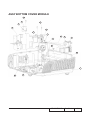
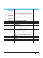
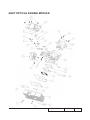
ASSY OPTICAL ENGINE MODULE
EX612/EX615
Confidential
Item
P/N
Description
1
2
23.8BA01G001
70.8EG18G001
PROJECTION LENS YM25
ASSY RELAY MODULE HD20
ASSY OPTICAL ENGINE MODULE EX615
(SERVICE)
YO CONDENSER 1 FOR A15W
SCREW PAN MECH M2.6*6 Ni NYLOK
PCBA DMD BD FOR X15-II XGA
ASSY ROD MODULE EX615 (SERVICE)
ASSY ROD MODULE EX615
ASSY ENGINE BOTTOM COVER Z15
0.55” XGA 2xLVDS SERIES 450 DMD -8 TI 1076603cB
DMD RUBBER EX615
DMD BOARD RUBBER X1161
STEP SCREW FOR TYPEX DMD M2.6*11.8mm,
X15
S450 0.55” XGA/SVGA DMD thermal pad, FUJIPOLY, Sarcon XR-HE, 18.4x12.5x0.5 mm
ASSY ENGINE BASE Z15
DMD HEATSINK AL6063 EX615
ASSY COLOR WHEEL MODULE EX612
CONDENSER LIGHT STOP EX615
YO CONDENSER 2 FOR A15W
ROD COVER NEW SUS301 X15
ROD SPRING SUS301,X15
SCREW PAN TAP M1.7*4 BLACK
HEX SCREW M3*H8*L5.3,BRASS
EMI GASKET W13*H15*L40
EMI GASKET W6*H13*L40
DMD MASK EX615
70.8EF40GR01
3
4
5
6
7
23.8AH20G011
85.1A526G060
80.8EF02G001
70.8EF42GR01
70.8EF36G001
70.8CP10G001
8
48.8CQ01G001
9
10
52.8CP01G011
52.8CP02G001
11
85.4A826G118
12
52.8CP04G001
13
14
15
16
17
18
19
20
21
22
23
24
70.8CP11G001
61.8EF02G001
70.8EF03G001
61.8EF03G001
23.8AH20G012
61.88N13G002
61.88N12G001
85.WA321G040
85.00823G080
41.83C01G001
41.8BV01G001
61.8EF01G001
EX612/EX615
Parts Supply
Confidential
V
V
V
V
XI
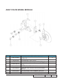
ASSY COLOR WHEEL MODULE
Item
P/N
70.8EF41GR01
1
2
61.8CP03G001
80.8EF04G001
3
23.8EF19G101
4
85.1A126G040
5
51.82Y29G001
6
7
52.83615G001
61.83628G001
Description
Parts Supply
ASSY COLOR WHEEL MODULE EX615
(SERVICE)
CW BRACKET SECC X1161
PCBA PHOTO SENSOR BOARD FOR EX615
YO 5S R76Y32G78W98B76 CW (WITH FTZS MOTOR)
SCREW PAN MECH M2.6*4 Ni
TAPE 3M J350 10*5mm FOR COLOR WHEEL
DP715
COLOR WHEEL DISC RUBBER, EzPro755
COLOR WHEEL SHOULDER SCREW,EzPro755
EX612/EX615
Confidential
V
V
XII
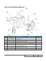
ASSY BlOWER MODULE
Item
P/N
1
49.8EF04G001
2
3
52.89T01G001
52.82G08G001
Description
Parts Supply
SUNON 45*20mm GB1245PKVX-8 F-TYPE
BLOWER (EX612/EX615)
BLOWER AIR TIGHT F12 H5350
BLOWER 4520 RUBBER EP7190
EX612/EX615
V
Confidential
XIII
ASSY FAN SHIELDING MODULE
9
2
8
6
1
7
3
4
5
Item
P/N
1
49.8EF03G001
2
3
4
5
61.8EG05G001
61.8EG11G001
85.1A123G080
85.1A123G060
6
43.8EG17G001
7
8
9
85.1A123G040
51.81540G001
41.8EF01G001
Description
Parts Supply
SUNON KDE1285PTV1 AXIAL FAN-LOW COST
(EX612/EX615)
8525 FAN SHIELDING HD20
LAMP BLOWER DUCT HD20
PAN SCREW M3*8 FOR YM-64 FRONT CELL&SP
SCREW PAN MECH M3*6 NI
THERMAL SWITCH WITH BRACKET (KLIXON
YS11) HD20 100C EX615
SCREW PAN MECH M3*4 Ni
TAPE 3M J350 17*60mm
EMI GASKET W5*H4*L80m
EX612/EX615
Confidential
V
V
XIV
A.K.
EX612/EX615
Confidential
XV
Parts
Supply
Item
P/N
Description
1
2
3
4
5
6
7
8
9
55.8EG01G011
55.8EG02G001
55.8EG03G001
70.8EG01G001
DC.8EF01G001
35.86301G001
51.00093G002
56.8EG01G001
56.8EG02G001
10
42.50112G001
11
12
42.00200G005
45.8EF01G001
CARTON OUTSIDE BOX AB FLUTE EX615
PARTITION PAPER RIGHT HD20
PARTITION PAPER LEFT HD20
LENS CAP ASSEMBLY HD20
D.C. EX615
SPEC LABEL BLANK PD120
PE BAG 400*520*0.07mm FOR OPTOMA
AIR BAG BOTTOM HD20
AIR BAG TOP HD20
CABLE POWER CORD 1830mm SP-023+IS14 EUR.
GREEN
CABLE VGA 15P 1.8M BLK EP739
REMOTE CONTROL OF Z15II WITH LASER
13
57.00001G001
PACK SIO2 DRIER 20g
14
15
16
51.00027G003
36.8EF02G001
36.8EF01G001
17
36.00012G002
18
36.00018G001
19
20
21
22
23
24
46.80S01G101
51.00200G001
51.00201G001
35.82001G111
35.00040G001
35.52302G091
PE BAG ZIPPER 33cm*25cm SIZE GREEN FOR OPTOMA
QUICK START CARD MULTILINGUAL OPTOMA EX615
USER’S GUIDE MULTILINGUAL (CD) OPTOMAEX615
WARRANTY CARD 3 YEARS, USA FOR OPTOMA LPP
SERIES
EXTENDED WARRANTY ; REGISTRATION FORM,USA
FOR LPP SERIES
BATTERY #7 1.5V NOVACELL
HANDLE BAR 2. PE HD70
HANDLE BAR 1.PE HD70
AK LABEL 3”*3” BLANK
LABEL 30mm,GREEN
LABEL CARTON 108*92 BLANK
EX612/EX615
Confidential
V
V
V
XVI
Appendix B
I. Serial Number System Definition
Serial Number Format for Projector (take EX615 as example)
Q
8EF
1
2
9
3
15
AAAAA
4
5
C 0001
6
7
1
:
Q = Optoma
2
:
8EF = Project Code
3
:
9 = Last number of the manufacture year (ex: 2009 = 9)
4
:
15 = week of the manufacture year (ex: the fifteenth week of the year = 15)
5
:
AAAAA = not-defined
6
:
C = Manufacture factory (CPC)
7
:
0001 = Serial Code
EX: Q8EF915AAAAAC0001
This label "Q8EF915AAAAAC0001" represents the serial number for EX615. It is produced
at CPC on fifteenth of 2009. Its serial code is 0001.
EX612/EX615
Confidential
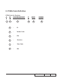
II. PCBA Code Definition
PCBA Code for Projector
A B
1
XXXXXXXXXX
2
3
1
:
ID
2
:
Vendor Code
3
:
P/N
4
:
Revision
5
:
Date Code
6
:
S/N
C
4
XXX 5
EEEE
6
EX612/EX615
Confidential
II