1
SERVICE MANUAL
HD25/HD25LV/HD25e
Date
Revise Version
Description
2012.12.17
V1.0
Initial Issue
2013.05.20
V2.0
Add HD25e
2013.07.25
V3.0
HD25/HD25LV
Change service mode:power,left,left meun to power,up,
right,up,left,menu (P17,P27,P31,P33)
TSE: Mina
Check: Amy
Approved: Alick
Preface
This manual is applied to HD25/HD25LV/HD25e projection system. The manual gives
you a brief description of basic technical information to help in service and maintain the
product.
Your customers will appreciate the quick response time when you immediately identify
problems that occur with our products. We expect your customers will appreciate the
service that you offer them.
This manual is for technicians and people who have an electronic background.Please
send the product back to the distributor for repairing and do not attempt to do anything
that is complex or is not mentioned in the troubleshooting.
Notice: The information found in this manual is subject to change without prior notice.
Any subsequent changes made to the data herein will be incorporated in future
edition.
HD25/HD25LV/HD25e Service Manual
Copyright May. 2013
All Rights Reserved
Manual Version 2.0
HD25/HD25LV/HD25e
Confidential
I
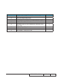
HD25/HD25LV/HD25e� �����������
Comparison �����
List
Parts
Main Board
ROD
Lamp Module
Engine Module
Color Wheel
HD25
HD25LV
HD25e
80.8RV01G002
80.8RU01G002
80.8VC01G001
70.8EG32GR01
70.8RU25GR01
SP.8RU01GC01
SP.8VC01GC01
70.8RV12GR01
70.8RV09GR01
70.8VC19GR01
70.8RV10GR01
70.8RU24GR01
HD25/HD25LV/HD25e
Confidential
II
Table of Content
Chapter 1
Introduction
Highlight
1-1
Compatible Mode
1-2
Chapter 2 Disassembly Process
Equipment Needed & Product Overview
2-1
Disassemble Top Cover Module
2-2
Disassemble Main board 2-2
Disassemble Lens
2-5
ROD Adjustment
2-6
Re-write Lamp Hours
2-7
Repair Action
2-8
Chapter 3
Troubleshooting
LED Lighting Message
3-1
Main Procedure
3-2
Pin Assignment
3-3
Chapter 4 Function Test & Alignment Procedure
Test Equipment Needed
4-1
Test Condition
4-1
VGA Port Test
Audio port Test
4-7
Video port Test
4-7
Component port Test
4-7
HDMI Port Test
4-8
3D Test
HD25/HD25LV/HD25e
4-2
4-8
Confidential
III
Run In Test
4-8
Test Inspection procedure
4-9
Auto Waveform and Factory Fan RPM
4-10
Chapter 5 Firmware Upgrade
Section 1: System Firmware Upgrade
5-1
5-3
Section 2: 8051 Firmware Upgrade Procedure
Appendix A Exploded Image
I
Appendix B
Serial Number System Definition I
PCBA Code Definition
II HD25/HD25LV/HD25e
Confidential
IV
Chapter 1
Introduction
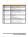
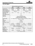
1-1 Highlight
No
Item
1
Dimensions (WxDxH)
2
Power Supply
3
Power Consumption
Description
● 324x234x97mm(WxDxH) (w/o feet)
● 324x234x112mm (WxDxH) (with feet)
● Auto-ranging: 100V ~ 240V ± 10%, 50-60Hz
For HD25/HD25LV
● Bright (Normal): TYP 308W MAX 339W @ 110V AC
TYP 297W MAX 327W @ 220V AC
● ECO Mode: TYP 250W MAX 275W @ 110V AC
TYP 241W MAX 265W @ 220V AC
For HD25e
● Bright (Normal): TYP 240W MAX 264W @ 110V AC
TYP 230W MAX 253W @ 220V AC
● ECO Mode: TYP 212W MAX 233W @ 110V AC
TYP 204W MAX 224W @ 220V AC
4
Keystone correction
● +/-40 degree is the scaler spec.
For HD25/HD25LV
● +/-12 degree is for system angle of V-keystone
For HD25e
● +/- 20 degree is for system angle of V-keystone
5
Throw ratio
● 1.5~1.8(D/W) @ 60”
6
Projection lens
● YM40Y
7
Lamp life
8
Lamp
For HD25/HD25LV
● Bright Mode (Normal Mode)
3500 Hours Standard @240W,50% Survival Rate
● STD Mode (ECO Mode)
5000 Hours Typical @190W,50% Survival Rate
For HD25e
● Bright Mode (Normal Mode)
4500 Hours Standard @190W,50% Survival Rate
● STD Mode (ECO Mode)
6000 Hours Typical @160W,50% Survival Rate
● 240W Philp E20.9(For HD25/HD25LV)
●190W Philp E20.9(For HD25e)
HD25/HD25LV/HD25e
Confidential
1-
No
Item
Description
● 0.65” S600, Dark Chip 3
● Number of active dots:1920x1080
For HD25
● 6S (R63G61B56R63G61B56)&7200rpm
For HD25LV/HD25e
● 6S (R81Y41G84C31W52B71)&7200rpm
9
DMD Chip&Number of
active dots
10
Color wheel
11
System controller
● TI DDP4422
Video compatibility
● NTSC: M/J ,3.58MHz, 4.43 MHz
● PAL: B, D, G, H, I, M, N, 4.43MHz
● SECAM: B, D, G, K, K1, L, 4.25/4.4 MHz
● HDTV: 720p(50/60Hz), 1080i(50/60Hz),1080P(24/50/
60Hz)
● SDTV:480i/p, 576i/p
Input signal spec
● VGA-in x2(for HD25e is only VGA-in)
● Composite Video x1
● HDMI v1.4
● Audio input (3.5mm jack)x 2
● RS232 control (9 pin)
● USB
�����������������������������������
type B(remote mouse simulation)
Altitude&Temperature
● Non-operation: Sea Level to 40,000 feet
Operating: Sea Level to 10,000 feet (@23°C);
manual switch to high altitude mode @5000 feet &
above
● Operating: 0 to 10,000 feet (5 to 40ºC)
Opefating Testing:5°C~40°C @ 0~2,500 feet
12
13
14
HD25/HD25LV/HD25e
Confidential
1-
1-2 Compatible Mode
Computer Compatibility
Compatibility
Resolution
Refresh Rate [Hz]
Analog
Digital
NTSC
720 x 480
60
-
-
PAL/SECAM
720 x 576
50
640 x 480
60
640 x 480
67
640 x 480
72
640 x 480
85
800 x 600
56.3
800 x 600
60.3
800 x 600
72
800 x 600
85
800 x 600
120
1024 x 768
60
1024 x 768
70.1
1024 x 768
75
1024 x 768
85
1024 x 768
120
1280 x 720
50
1280 x 720
60
1280 x 720
120
1280 x 768
60
1280 x 768
75
1280 x 768
85
1280 x 768
60
1366 x 768
60
1440 X 900
60
○
○
○
○
○
○
○
○
○
○
○
○
○
○
○
○
○
○
○
○
○
○
○
○
○
○
○
○
○
○
○
○
○
○
○
○
○
○
○
○
○
-
VGA
SVGA
XGA
HD720
WXGA
WXGA+
HD25/HD25LV/HD25e
Confidential
1-
Compatibility
Resolution
Refresh Rate [Hz]
Analog
Digital
1280 x 1024
60
1280 x 1024
75
1280 x 1024
85
SXGA+
1400 x 1050
60
UXGA
1600 x1200
60
1920 x 1080p
24
1920 x 1080p
30
1920 x 1080p
50
1920 x 1080p
60
1920 x 1080i
50
1920 x 1080i
60
SDTV
720 x 576i
50
SDTV
720 x 576p
50
SDTV
720 x 480i
60
SDTV
720 x 480p
60
○
○
○
○
○
○
○
○
-
○
○
○
○
○
○
○
○
○
○
○
○
○
○
○
SXGA
HDTV
HDTV
Note: If the Computer Compatibility supportive signal is different from User’s Manual,
please refer to User’s Manual.
HD25/HD25LV/HD25e
Confidential
1-
Chapter 2
Disassembly Process
2-1 Equipment Needed & Product Overview
1. Screw Bit (+): 105
2. Screw Bit (+): 107
3. Screw Bit (-): 107
4. Hex Sleeves: 5 mm
5. Tweezers
6. Projector
* Before you start: This process is protective level II. Operators should wear electrostatic chains.
* Note: - If you need to replace the main board, you have to record the lamp usage hour.
- Some related contents please refer to common SM chapter 2.
HD25/HD25LV/HD25e
Confidential
2-
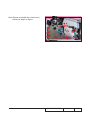
2-1 Repair notice
2-1-1 Disassemble Top Cover
Module
1. Unscrew 3 screws (as red circle) from
the Bottom Cover.
2. Press two sides of the projector and push
them as the blue arrow.
3. Remove the Top Cover Module.
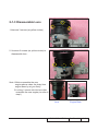
2-1-2 Disassemble Main
Board
1. Unplug 1 connector (as green square) to remove the FPC cable.
2. Unplug 8 connectors (as yellow square).
3. Unscrew 6 screws (as red circle) from the Main Board Module.
FPC cable
HD25/HD25LV/HD25e
Confidential
2-
4. Unscrew 2 screw (as blue circle) from the IO Cover.
HD25/HD25LV
5. Unscrew 8 hex screws (as green circle) from the IO Cover.
note:For HD25e only need to unscrew 4
hex screws (as green circle) from the
IO Cover.
HD25e
6. Unplug 1 connector (as orange square).
7. Disassemble the Main Board.
Note: - Make sure cables plug into the
correct ports when assembling the
unit.
Main Board
HD25/HD25LV/HD25e
Confidential
2-
Note: - Make sure cables plug into the correct ports when assembling the unit.
Please refer to the below table details of
each connector on Main Board.
G
Male Connector
on Main Board
Item
F
E D
The key feature
Speaker
(position G is not for
HD25e)
Compose of Red/Black Wire and
Black wire tube (2 pin)
B
Lamp Driver
Black wire tube (5 pin)
C
System Fan
Compose of Red/Yellow/Black
Wire (3 pin)
D
Photo Sensor
Compose of Red/Black/White
Wire and White wire tube (3 pin)
E
Blower
Compose of Red/White/Black
Wire and White wire tube (3 pin)
F
IR
A&G
C
B
A
Figure
Compose of Black/Yellow/Red
Wire and Gray wire tube (3 pin)
HD25/HD25LV/HD25e
Confidential
2-
Note:Please assemble the main board
follow the steps as figure.
10 11
4
9
1
5
8
2
HD25/HD25LV/HD25e
3
Confidential
7
6
2-
2-1-3 Disassemble Lens
1.Unscrew 3 screws (as yellow circles)
2. Unscrew 3 screws (as yellow circles) to
disassemble lens .
Note:1.Before assemble the new
engine,please clean the dusty from
engine base by air gun firstly .
2.Locking 3 screws into the lens after
assemble the new engine.(as refer to
step1)
Lens
HD25/HD25LV/HD25e
Engine Base
Confidential
2-
2-2 Rod Adjustment
1. Environment Adjustment
- The distance between the engine and
the screen is 1.8M.
- This process should be done at a dark
environment (under 2 Lux).
2. Procedure Adjustment
- Change
the screen to "white screen".
- Adjust the screws by using the rod
on the engine module to readjust the
image.
("screw 1" should be adjusted first, and then "screw 2". Adjust until the yellowish
or bluish parts disappeared.)
2
3. Abnormal image inspection
- It should not have any abnormal color
at the rim of the image by estimating
through the eyes.
1
Note: - To avoid over adjusting the rod.
- After the operation, please use the glue
to fix the screws.
HD25/HD25LV/HD25e
Confidential
2-
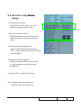
2-3 Re-write Lamp ������
Hours
Usage
1. Get into service mode
- Press (power→up→right→up→left→
Menu) to get into service mode.
2. Re-write Projection Hours
-Select Projection Hours and use “left” or “
right” buttons to re-write the projection
hours.
3. Re-write Lamp Hours(Normal)
-Select Lamp Hours(Normal) and use
“left” or “right” buttons to re-write the lamp
hours(Normal).
4. Re-write Lamp Hours(ECO)
-Select Lamp Hours(ECO) and use “left”
or “right” buttons to re-write the lamp
hours(ECO).
5. Choose “Exit”, press “Enter” to exit
Note: left key = decrease lamp hour
right key =increase lamp hour
HD25/HD25LV/HD25e
Confidential
2-
2-4 Repair Action
Change parts
Repair action
Main
Board
Lamp
Engine
Module Module
Lamp
Driver
Blower
Color
Wheel
Software
Firmware
Description
EDID page
Firmware Update
v
Color Wheel Index
v
OSD Reset
v
EDID
v
Chapter 6
Re-write Lamp
Hours Usage
v
Chapter
2-3
Video port test
v
chapter
4-4-3
Auto Waveform and
Factory Fan
RPM
v
Optical
Performance
Measure
v
v
Chapter
4-4-1.7
v
v
v
v
Chapter 5
v
v
v
Chapter
4-6.2
Chapter
4-3
Chapter
4-4-8
v
HD25/HD25LV/HD25e
Confidential
2-
Chapter 3
Troubleshooting
3-1 LED Lighting Message For Projector
Message
Power LED
(Red)
Power LED
(Green)
Temp LED
(Red)
Lamp Led
(Red)
Standby State
(input power cord)
Power on (Warming)
Flashing
Power on and Lamp
lighting
Power off (Cooling)
Note:
Flashing
Error
(Lamp failed)
Flashing
Error
(Fan failed)
Flashing
Error
(Over Temp.)
Flashing
Steady light
Flashing
No light
HD25/HD25LV/HD25e
Confidential
3-
3-2 Main Procedure
The other troubleshooting procedures please refer to common service manual
3-1(Main Procedure).
No
Procedure
Symptom
- Check LED Status
a. Power LED and Lamp LED light on red
- Check Lamp
- Check Lamp Driver
- Check Main Board
b.Power LED flashes red, and Temp LED flashes red
1
Auto Shut Down
- Check Fan
- Check Main Board
- Check Photo Sensor Board
- Check whether have execute auto Waveform and Factory Fan
RPM
c. Power LED flashes red, Temp LED light on red
- Check Main Board
2
3D Image
Abnormal
- Check Color Wheel
- Ensure the using 3D glasses is good and you must face the
projection.
- Ensure the CD in DVD is 3D format
- Ensure your standing distance is less than 6m from screen.
- Ensure the 3D function is on and execute “3D sync invert” in OSD
menu.
- Check main board
HD25/HD25LV/HD25e
Confidential
3-
3-3 Pin Assignment
Power on the projector and measure the pins as below:
J23:16 PIN POWER From LVPS
J23
PIN
Description
Voltage(V)
1
12V
12
PIN 9
2
12V
12
3
12V
12
4
GND
0
5
GND
0
6
GND
0
7
GND
0
PIN
Description
Voltage(V)
8
GND
0
1
FAN-V1
6.18
9
PFC ON1
3.97V
2
FAN1
0(operation)/3.3(fan lock)
10
GND
0
3
GND
0
11
GND
0
12
GND
0
J3:IR
PIN 8
J9:Blower
PIN
Description
Voltage(V)
1
FAN-V2
8.42
2
FAN-2
0(operation)/3.3(fan lock)
3
GND
0
J4:System FAN
PIN 1 PIN 16
13
5V
5
PIN
Description
Voltage(V)
14
12V
12
1
IR-P1
5.08
15
12V
12
2
GND
0
16
12V
12
3
IR-P2
5.05
J11:Lamp driver
J5:Photo sensor
PIN
Description
Voltage(V)
1
LAMPLIT_IN
4.38
PIN
Description
Voltage(V)
2
GND
0
1
J15-1
1.14
3
P5V
5
2
PHOTO-IN
0.52
4
LAMPEN_OUT
5
3
GND
0
5
D-MODE6
4.8
PIN 1
PIN 5
J4
J3
J11
PIN 3
PIN 1
PIN 3
J9
J5
PIN 1
PIN 3
PIN 1
HD25/HD25LV/HD25e
PIN 3
Confidential
PIN 1
3-
Chapter 4
Test & Inspection
4-1 Test Equipment Needed
- PC with HDTV resolution
- DVD player with Multi-system, equipped “Component”, “Composite”, “S-Video” and “HDMI”.
- HDTV Source (720P,1080P,1080i)
- Minolta CL-100
- Quantum Data 802B or CHROMA2327 (Color Video Signal & Pattern Generator)
4-2 Test Condition
- Circumstance brightness: Dark room less than 2 lux.
- Product must be warmed up for 3 minutes.
- Screen size: 60 inches diagonal.
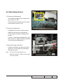
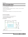
Zone Definition
< Figure: Zone A, Zone B & Frame (as green line) Definition, Active area=Zone A+ Zone B >
HD25/HD25LV/HD25e
Confidential
4-
4-3 Auto Waveform and Factory Fan
RPM
After replacing main board, blower, lamp driver or
upgrading the firmware, please follow steps as below:
1. Plug in power cord,hold “Menu”,”UP” buttons
simultaneously and press “POWER” button.Loosen
“Menu”,”UP”buttons until“Lamp” and “Temp” LED light red.
2.Wait a moment, please get into service mode then
check the “Blower Factory RPM” .
Note:
- If the Factory FAN RPM Value doesn’t show in
service mode, please repeat the step again.
- Make sure the “Blower record (rpm) “is 34904730.
HD25/HD25LV/HD25e
Confidential
4-
4-4 I/O Port Test
4-4-1 VGA Port Test
Note: the native resolution of test signal is 1920x1080@60HZ.
1. Frequency and tracking boundary
Procedure - Test equipment: video generator.
- Test signal: analog1920����������
x1080�����
@60Hz
- Test Pattern: general-1 or master
- Check and see if the image sharpness is well
performed.
- If not, re-adjust by the following steps:
(1) S
elect “Frequency” function to adjust the image
appears to flicker vertically.
(2) S
elect “Phase” function and use right or left
arrow key to ��������������������������������
image appears to be unstable or
flickers.
- Adjust Resync or Frequency/Phase/H. Position/V.
Position to the inner screen.
Inspection item
- Eliminate visual wavy noise by Resync, Frequency
or Tracking selection.
- Check if there is noise on the screen.
- Horizontal and vertical position of the video should
be adjustable to the screen frame.
Criteria
- If there is noise on the screen, the product is considered as failure product.
- If there is noise on the screen, use auto or manual
“frequency” function or “tracking” function to adjust
the screen.
- The PC mode functionally sure be workable include
support format with frequency and auto detected
functional will be workable.
General-1
Master
HD25/HD25LV/HD25e Confidential
4-
2. Bright Pixel
Procedure - Test equipment: video generator.
- Test signal: analog 1920x1080@60Hz
- Test Pattern: gray 10
Inspection item
- Bright pixel check.
Criteria
- Bright pixel is unacceptable in the active zone; 1
pixel is allowed on the frame.
- Ref. Defect specification table
Gray 10
3. Dark Pixel
Procedure - Test equipment: video generator.
- Test signal: analog 1920x1080@60Hz
- Test Pattern: full white
Inspection item
- Dead pixels check.
- White pattern (IRE=100)
Criteria
- The dead pixel is unacceptable on full white pattern in zone A and no more than 2 dark pixels in
zone B
- Adjacent pixels are unacceptable.
- Please refer to Pixel specification table.
Full white
4. Bright Blemish
Procedure
- Test equipment: video generator.
- Test signal: analog 1920x1080@60Hz
- Test Pattern: gray 10
Inspection item
- Bright blemish check.
Criteria
- The bright blemish is unacceptable under gray
10 pattern in zone A and no more than 4
bright blemish in zone B.
Gray 10
- Please refer to Pixel specification table.
5. Dark Blemish
Procedure
- Test equipment: video generator.
- Test signal: analog 1920x1080@60Hz
- Test Pattern: blue 60
Inspection item
Blue 60
- Dark blemish check
HD25/HD25LV/HD25e
Confidential
4-
Criteria
- The bright blemish is unacceptable under blue
60 pattern in zone A and no more than 4
bright blemish in zone B.
- Please refer to Pixel specification table. .
Pixel specification
Order
1
Symptom
Bright pixel ( dots)
Pattern
Gray 10 pattern
Criteria
2
Dark pixel(dots)
White pattern
A=0
B≤2
3
Unstable pixel (dots)
Any pattern
A+B=0
4
Adjacent pixel (dots)
Any pattern
A+B=0
5
Bright blemish (Dirty)
Gray 10 pattern
A=0
B≤4
(diameter<1 inch)
6
Dark Blemish(Dirty)
Blue 60 pattern
A=0
B≤4
(diameter<1 inch)
7
Bright pixel on frame
Gray 10 pattern
=0
A+B=0
6. Focus Test
Procedure - Test equipment: video generator.
- Test signal: analog ��������������
1920x1080�����
@60Hz
- Test Pattern: full screen
Inspection item
- Focus check
Criteria
-From screen 1.8M via visual to check the focus,
look at the entire screen, focus shall be clear, crisp,
and sharp over the entire surface of the display pattern. (Blur word on one of the corner after adjustment is acceptable. However, the word should at
least be recognizable.)
Full screen
7. Color Performance
Procedure - Test equipment: video generator.
- Test signal: ������������������������
1920x1080���������������
@60Hz, 1080i
- Test Pattern: 64 gray RGBW
Please get into service mode.Use
720p & 1080p signal, pattern to do color
performance. Color cannot discolor to purple and
blue.
HD25/HD25LV/HD25e Confidential
4-
Inspection item
- Check if each color level is well-functioned.
- Color saturation
Criteria
- Screen appears normal. It should not have any
abnormal condition, such as lines appear on the
screen and so on.
- Color appears normal.
- It is unacceptable to have few lines flashing.
- RGBW should all appear normal on the screen
and sort from R-G-B-W.
- Color levels should be sufficient and normal. (The
unidentified color levels on both left and right
sides should not over 4 color levels.)
- Gray level should not have abnormal color or
heavy lines.
- If color appears abnormal, please get into service
mode to do color wheel index adjustment.
64 gray RGBW
8. Optical Performance
Inspection Condition
- Environment luminance: 2 Lux
- Product must be warmed up for 5 minutes
- Distances from the screen: 1.8M
- Screen Size: 60 inches diagonal
a. Measure setting
Procedure - Please get into OSD menu, select “Lamp Setting”
under “Options”, press “Enter” button, then select
“Bright “mode.
- Press “Power →Up →Right →Up →Left →Menu”
to get into service mode.
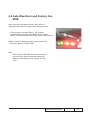
- Test equipment:Select “Spoke Test”.
HD25/HD25LV/HD25e
Confidential
4-
b. Brightness
Procedure - Full white pattern
- Use CL100 to measure brightness values of P1~P9.
- Follow the brightness formula to calculate
brightness values.
☼ Brightness Formula
Avg. (P1~P9)*1.1m2
Criteria
• 618 ANSI lumen (HD25)
1287 ANSI lumen (HD25LV)
792 ANSI lumen (HD25e)
Full white pattern
c. Full On/Full Off Contrast
Procedure
- Full white pattern & Full black pattern
- Use CL100 to measure brightness values of full
white pattern P5 & full black pattern B5 ( see
image: full white)
- Follow Contrast formula to calculate contrast
values.
☼ Contrast Formula
P5/B5
Note: P
5 = Lux of center in full white pattern
Criteria
Full black pattern
B5 = Lux of center in full black pattern
• 1530:1
d. Uniformity
Procedure
- Full white pattern
- Use CL100 to measure brightness values of
P1~P9 (see image: full white).
- Follow the Uniformity formula to calculate
average values.
☼ Uniformity Formula
JBMA Uniformity = Avg. (P1, P3, P7, P9) /
P5 *100%
Criteria
Full white pattern
• 70%
HD25/HD25LV/HD25e Confidential
4-
4-4-2 Audio Port Test
Procedure
- Test equipment: DVD Player
- Test signal: CVBS
Inspection item - Audio performance test
Inspection Distance - 1.4M ~1.6M
Criteria
- Check the sound from speaker
- Plug Audio cable into Audio in port,
check whether “Volume” is normal.
- Adjust the volume to “0→ 8” by using the
remote controller.
- Check the sound from speaker.
4-4-3 Video Port Test
Procedure
- Test equipment: DVD player
- Test signal: Video
Inspection item
- Video performance test
Motion video
Inspection Distance - 1.4M ~1.6M
Criteria
- Check any abnormal color, line distortion or any noise on
the screen.
- Check the sound from speaker.
4-4-4 Component Port Test
Procedure - Test equipment: DVD player
- Test signal: Ycbcr/YPbPr
Inspection item
- HDTV performance test
InspectionDistance - 1.4M ~1.6M
Criteria
-C
heck any abnormal color, line distortion or any noise on
the screen.
HD25/HD25LV/HD25e
Confidential
4-
4-4-5 HDMI Port Test
Procedure - Test equipment: DVD Player with HDMI output.
- Test signal: 720p, 1080p, 1080i
Inspection item
- HDMI performance test.
Inspection Distance - 1.4 M ~1.6M.
Criteria - Ensure the image is well performed and the color can not discolor.
- Check whether "mute" is normal.
4-5-6 3D Test
Procedure
Inspection item
- Test equipment: 1. Blue-Ray DVD player & 3D format CD
- Test signal: 1080i�����
@50Hz
- 3D test (HDMI)
Inspection Distance
- 3~5 M
Criteria
- The image should not appear noise, flicker shadow, shocking,
abnormal color.
4-5 Run In Test
- Temperature: 15°C~35°C
- Circumstance brightness: Normal environment
- Screen size: No concern
- Display mode: ECO mode
After repairing each unit, a Run-in test is necessary (refer to the below table).
Symptom
Normal repair
NFF
Auto shutdown
Run-in Time
2 hours
4 hours
6 hours
- Get into Burn-In Mode
* Cycle setting is based on the defect symptoms. ie: If it is NFF, the run-in time is 4 hours. You have
to set the lamp on for 50 min. and lamp off for 10 min for 4 cycles.
HD25/HD25LV/HD25e Confidential
4-
Press power >up > right > up >left >menu buttons sequentially on remote controller to get into
service mode.
Choose Burn-In Test > enter
Lamp On
Press right key to adjust the time (50)
Lamp Off
Press right key to adjust the time (10)
Set burn in cycle
Press right key to adjust the cycle
After setting up the time, choose “Get into Burn-In Mode” and press enter
4-6 Test Inspection Procedure
1. Check Points
Check item
Check point
Firmware version
All firmware version must be the latest version
TB implementation
Related TB must be implement
Cosmetic
Cosmetic can not be broken
Logo
Missing logo, missing prints and blurry prints are
unacceptable
Lamp cover
It should be locked in the correct place.
Zoom in/out
The function should work smoothly
Keypad
All keypad buttons must operate smoothly
2. OSD Reset
After final QC step, we have to erase all saved change again and restore the
OSD default setting.
The following actions will allow you to erase all end-users' settings and restore
the default setting:
(1) Please enter OSD menu.
(2) Choose "Option" and then execute "Reset" function
HD25/HD25LV/HD25e
Confidential
4-10
Chapter 5
Firmware Upgrade
Section 1: System Firmware Upgrade
5-1-1 Equipment Needed
Software: (DDP4422-USB)
- DLP Composer Lite 11.0.2
- Firmware (*.img)
- 11.0.2 FlashDeviceParameters
Hardware:
- Projector
- Power Cord (42.50115G001)
- Cable USB-A to USB-B(42.87304G001)
- PC or Laptop
Note1: we will show the hot key of fw mode and how to check FW version,the other contents please refer to common manual 5-1 .
Note2: During FW upgrade procedure,please select "64KB" in "Skip Boot Loader Area".
Note3: Put "11.0.2 FlashDeviceParameters” file into the folder where you setup “DLP Composer
Lite 11.0.2"
HD25/HD25LV/HD25e
Confidential
5-
5-1-2 Get into FW mode
1. Get into Firmware mode
- Plug in power cord to projector.
-�
Hold
���� �������������������������
”power” button until the “power”
��������������������
LED status
goes to steady orange, the Temp LED and Lamp
LED will light on red.
- Loosen the “POWER” button.
- Connect the projector with PC by USB cable.
5-1-3 Check FW version
1.Restart the unit and enter the Service Mode.
Press Power --> Up --> Right--> Up -->Left-->
Menu.
2.The firmware version will be shown as red circle on the screen.
HD25/HD25LV/HD25e
Confidential
5-
Section 2: MCU FW Upgrade Procedure
5-2-1 Equipment Needed
Software :
- Coretronic ICP Programmer, v6.00
- USB-to-Serial COM port Driver (PL2303_Prolific_DriverInstaller_v1417.exe)
- Program file (*.TPJ)
Hardware :
- Projector
- Power Cord (42.50115G001)
- ICP FIXTURE (SP.8JC08G001)
- PC or Laptop
HD25/HD25LV/HD25e
Confidential
5-
5-2-2 Setup Procedure
Install ICP Utility
1.Double click "Setup,ICP Utility, v6.00.exe".
2.Click "Next".
3. Click "Next".
4. Click "Next".
HD25/HD25LV/HD25e
Confidential
5-
5. Click "Finish" to end ICP Utility
installed.
Install PL2303_Prolific_Driver
6. Double Click "PL2303_Prolific_DriverInstall
er_v1417.exe"
7. Click "Next".
8. Click
����������������������
"Finish" to end PL2303_Prolific_Driver
installed.
HD25/HD25LV/HD25e
Confidential
5-
5-2-3 Upgrade Procedure
1.Connect the PC and projector (VGA in)
by ICP FIXTURE and plug in the power
cord.
Note:For HD25/HD25LV please insert in the
VGA-2 port.
For HD25e please insert in the VGA
port.
Note: please properly plug into the fixture
board by 4pin cable (as the square
shown).
Gnd
2.Select "Start" -->"Coretronic Tools"
-->"Coretronic ICP Utility V6.00" to run
"ICP Utility.exe”.
3.Click "Load Proj" to open the “TPJ” file
which you will upgrade MCU firmware
file,then click " Update Chip" to upgrade the
MCU firmware.
HD25/HD25LV/HD25e
Confidential
5-
5. Finish
- When MCU FW upgrade process is finished, "PASS" will be shown.
6. Re-plug in power cord and power on the
projector. Get into the service mode to
check the MCU firmware version.
HD25/HD25LV/HD25e
Confidential
5-
Section 3: MSP FW Upgrade Procedure
(For HD25/HD25LV)
5-3-1 Equipment Needed
Software :
- FET-Pro430-Lite Setup Procedure (Setup.exe)
- Program file (*.d43)
Hardware :
- Projector
- Power Cord (42.50115G001)
- MSP430 FIXTURE (75.8KC16GR01)
- PC or Laptop
- USB Cable mini USB to USB (A) (42.00284G001)
HD25/HD25LV/HD25e
Confidential
5-
5-3-2 FET-Pro430-Lite Setup Procedure
1. Choose “Setup.exe” Program.
2. Read “License Agreement”.
- Choose I accept and agree to be bound
by all the terms and conditions of this
License Agreement”.
- Click “Next”.
3. Click “Next”.
HD25/HD25LV/HD25e
Confidential
5-
4. Choose installation options and click
“Next”.
5. Click “Next”.
6. Click the browse button to change the
downloading location to “program files”.
- Select “everyone”
- Click “Next”.
HD25/HD25LV/HD25e
Confidential
5-10
7. Click “Next”.
8. The program is being installed.
9. Click “Next”.
HD25/HD25LV/HD25e
Confidential
5-11
10. Click “Close”.
5-3-3 USB Driver Upgrade Procedure
1. Get into Firmware mode
- Plug in power cord to projector.
-�
Hold
���� �������������������������
”power” button until the �������������������������
“power” LED status goes
to steady orange, the Temp LED and Lamp LED will
light on red.
- Loosen the “POWER” button.
- Plug the VGA port of MSP430 fixture into the VGAout port of projector and connect the PC with
MSP430 fixture by mini-usb cable.
2. The window “Hardware Update Wizard” will show
automatically.
- Select “Install from a list or specific
location(Advanced)”
- Click” Next”
HD25/HD25LV/HD25e
Confidential
5-12
3. Select “Include this location in the search”
- Click the browse button to change the downloading
location
- Select” LaunchPad_Driver_slac524”
- Click”Ok”
- Click”Next”
4. Writing system registry values.
5.�������
Click “Finish”.
���������
Note: If the PC appear “Found New Hardware Wis
zard” picture again, repeat step 2 to install USB
Drivier once more.
HD25/HD25LV/HD25e
Confidential
5-13
5-3-4: MSP FW Upgrade Procedure
1. Double click “Lite FET-Pro430”.
2. Select “Setup->Connection/Device Reset”, click
“Connection/Device Reset”.
3. Select options as right photo marks.
- Click “ Ok” .
HD25/HD25LV/HD25e
Confidential
5-14
4. Select ”MSP430G2xx” .
5.Select “MSP430G2513”
6. Select “Open Cord File”
- Choose “MSP430X.d43 ”(MSP430
firmware)
- Click “Open” .
HD25/HD25LV/HD25e
Confidential
5-15
7. Select “Setup->Memory Options”, click
“Memory Options”
8. Select options as right photo marks.
- Click “ Ok” .
9. Click “Auto Prog”.
- The firmware will start to update .
HD25/HD25LV/HD25e
Confidential
5-16
10. Get into the service mode to check the
MSP430 firmware version.
HD25/HD25LV/HD25e
Confidential
5-17
Chapter 6
EDID Upgrade
6-1 EDID Upgrade Procedure
- The upgrade procedure for VGA and HDMI ports please refer to common service manual
chapter 6.
- Please use " EDID 0.81.exe" Program and Key in the serial number into the "Unit No" blank
space.
HD25/HD25LV/HD25e
Confidential
6-
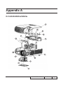
Appendix A
D.C.HD25/HD25LV/HD25e
4
11
9
10
15
14
3
13
12
1
5
2
8
7
6
HD25/HD25LV/HD25e
Confidential
Item
1
2
3
4
5
6
7
8
9
10
11
12
13
14
15
Description
Parts
Supply
ASSY BOTTOM COVER MODULE HD25LV
SPEAKER 8FB 8W 8-OHM WITHOUT TUBING HD25LV
ASSY MAIN BOARD MODULE HD25
ASSY TOP COVER AND ZOOM RING MODULE EH1020
FOCUS RING BLACK HD200X (FOR YM40)(LGSM)
ASSY LAMP COVER BLACK FOR EX615 (SERVICE)
LAMP COVER BLACK EX615(LGSM)
LOCK SCREW PAN MECH M3*8.5-3.5 BLACK(1018+HEAT
TREATMENT)
ASSY PHILIPS E20.9 240W LAMP MODULE HD25LV
LAMP MODULE FOR PROJECTOR HD25e
ASSY PHILIPS E20.9 240W LAMP MODULE HD25LV
SCREW PAN MECH M3*5 Ni
TOP COVER SHIELDING HD20s
SCREW DOUBLE FLAT MECH M2*3Ni
PAN SCREW M3*8 FOR YM-64 FRONT CELL & SP
SCREW PAN MECH M2.6*6 Ni NYLOK
ASSY 8525 FAN SHIELDING MODULE HD25LV
SCREW PAN MECH M3*6 NI
HD25/HD25LV/HD25e
V
V
V
V
Confidential
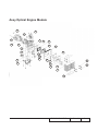
Assy Optical Engine Module
24
4
14
6
9
27
22
12
1
13
17
16
15
3
5
23
28
2
21
20
18
25
19
8
11
26
10
7
29
HD25/HD25LV/HD25e
Confidential
Item
1
2
3
4
5
6
7
8
9
10
11
12
13
14
15
16
17
18
19
20
21
22
23
24
25
26
27
28
29
Description
ASSY OPTICAL ENGINE MODULE FOR 8RV(SERVICE)
ASSY OPTICAL ENGINE MODULE FOR 8VC(SERVICE)
ASSY ENGINE BASE MODULE H15 ADD BOSS HD25LV
ASSY ROD MODULE FOR HD20 (SERVICE)
ASSY ROD MODULE FOR 8RU(SERVICE)
ASSY ROD MODULE HD20
ASSY RELAY MODULE EW762
ASSY COLOR WHEEL MODULE FOR 8RV (SERVICE)
ASSY COLOR WHEEL MODULE FOR 8PJ (SERVICE)
ASSY COLOR WHEEL MODULE HD25
ASSY ENGINE BOTTOM HD20
Projection Lens TR1.5 - 1.8 (YM40Y)
DMD HEATSINK AL6063 H15
Parts Supply
V
V
V
V
V
V
S450 0.55” XGA/SVGA DMD thermal pad, FUJIPOLY, Sarcon
XR-HE, 18.4x12.5x0.5 mm
SPRING FOR DMD STEP SCREW X1161
STEP SCREW FOR DMD M2.6*16.2mm X1161
SPRING FOR DMD STEP SCREW X116
DMD 1920*1080 PIXEL 0.65” 1080P 2xLVDS DC3 S600 19106037E
CNNT F 350P 0.55” 1080P S600 BGA DMD ZIF SOCKET
EPZ350;FOXCONN
HEX SCREW M2.6*H8*L4,BRASS
CONDENSER LIGHT STOP SUS304 0.3t 1609WX
KINKO CONDENSER 1 FOR A15W
KINKO CONDENSER 2 FOR A15W
DMD INSULATION PC A15
DMD PLATE AL A6061 M409WX
ROD COVER WXGA HYBRID K750
ROD SPRING SUS301 HD20
DMD ANTIDUST RUBBER 739 SILICONE RUBBER
PCBA DMD BOARD FOR HD21 PROJECTOR
SCREW PAN MECH M2.6*6 Ni NYLOK
DMD HEATSINK SPRING SUS304 M409WX
DMD SHOULDER SCREW SB21
SCREW PAN TAP M1.7*4 BLACK
GASKET W*10 H*10 L*40
EMI GASKET W13*H6*L35
HD25/HD25LV/HD25e
Confidential
V
V
Assy Color Wheel Module
3
2
1
Item
1
2
3
Description
EIS CW 6S Φ42 R59G63B58R59G63B58 URD20VA6
9.4MM
PCBA PHOTO SENSOR BOARD FOR EW762 PROJECTOR
Parts Supply
V
D42 CW HOLDER COVER HD20
HD25/HD25LV/HD25e
Confidential
Top Cover Assembly
4
5
1
3
2
Item
Description
1 TOP COVER ASSEMBLY HD25 WHITE(LGSM)
2 KEYPAD PLATE ENTER HD20(LGSM)
3 KEYPAD PLATE HD25LV (LGSM)
Parts Supply
V
HD25/HD25LV/HD25e
Confidential
Keypad Assembly
1
4
3
2
Item
1
2
3
4
Description
KEYPAD PLATE ENTER EX612(LGSM)
KEYPAD 3M TAPE HD20
PCBA KEYPAD BD FOR SC 1080P
FFC KEYPAD TO FORMATTER BD 16P P=0.5 122mm
1209S 成朋
HD25/HD25LV/HD25e
Parts Supply
V
Confidential
Assy Bottom Cover Module
6
5
7
8
4
3
1
Item
1
2
3
4
5
6
7
8
Description
8HW BOTTOM COVER WHITE LN2520 LGSM
ADJUST FOOT P1266
YH-NUT-M2.0*2.0*4.0
8EG BOTTOM SHIELDING T=0.6MM
SECURITY BAR EX525ST
SECURITY BAR CAP PC LN2520 WHITE HD20
SCREW PAN TAP M3*5 Ni
EMI GASKET W5*H1.0*L155mm PD527
HD25/HD25LV/HD25e
2
Parts Supply
V
Confidential
Assy LVPS Module
Item
1
2
Description
POWER SUPPLY,AD-320W,INLET,200*50,DL,T-SW
230W LVPS MYLAR PC T=0.43 HD20
HD25/HD25LV/HD25e
Parts Supply
V
Confidential
Assy Lamp Driver Holder Module
3
2
4
6
1
5
item
Description
1
SCREW PAN MECH M3*5 Ni
2
W.A. 2P #22 FEMALE 6KV 150C 95mm FOR LAMP
DRIVER PDG-DSU30
3
SCREW CAP MECH M2*4 Ni
4
LAMP DRIVER HOLDER PPS+40%GF HD20
5
LAMP DRIVER PHILIPS EUC 240d N/T05, 135*50,
DL, ImageCare
HD25/HD25LV/HD25e
Parts Supply
V
Confidential
10
Assy Main Board Module
1
6
5
3
4
2
Item
1
2
3
4
5
6
Description
PCBA MAIN BOARD FOR HD25 PROJECTOR
MAIN BOARD SHIELDING HD25LV
ASSY IO COVER MODULE FOR 8RV WHITE(SERVICE)
Parts Supply
V
V
IO COVER WHITE HD25LV (LGSM)
SCREW PAN TAP M3*6 Ni
SCREW HEX I/O #4-40 H4*L8 NI NYLOK
SCREW PAN MECH M3*5 Ni
HD25/HD25LV/HD25e
Confidential
11
Assy 4520 Blower Module
2
1
3
Item
1
2
3
Description
SUNON 45x20 BLOWER, F TYPE , wire length 150mm ,
heat-shrink length 1
BLOWER AIR TIGHT F12 H5350
BLOWER 4520 RUBBER EP7190
HD25/HD25LV/HD25e
Parts Supply
V
Confidential
12
Assy 8525 Fan Shoelding Module
9
2
8
6
1
7
3
5
4
HD25/HD25LV/HD25e
Confidential
13
Item
1
2
3
4
5
6
7
8
9
Description
SUNON KDE1285PTV1 AXIAL FAN-LOW COST
8525 FAN SHIELDING HD20
LAMP BLOWER DUCT HD20
PAN SCREW M3*8 FOR YM-64 FRONT CELL & SP
SCREW PAN MECH M3*6 NI
THERMAL SWITCH WITH BRACKET (KLIXON YS11)
HD20 100C
SCREW PAN MECH M3*4 Ni
TAPE 3M J350 17*60mm
EMI GASKET 4*3&51mm S15E
HD25/HD25LV/HD25e
Parts Supply
V
V
Confidential
14
Assy Packing Drawing
HD25/HD25LV/HD25e
Confidential
15
Item
1
2
3
4
5
6
7
8
9
10
11
12
13
14
15
16
17
18
19
20
21
22
23
24
Description
CARTON OUTSIDE BOX AB FLUTE HD25
CABLE VGA 15P 1.8M BLK EP739
PARTITION PAPER LEFT HD20
LENS CAP ASSEMBLY HD20 BLACK
D.C. HD20
SPEC LABEL BLANK PD120
PE BAG HD20
AIR BAG BOTTOM HD20
AIR BAG TOP HD20
CABLE POWER CORD 1830mm SP30+IS14;BC-PUPIXY01
CABLE POWER CORD 1.8M SP30+IS14 US
INSTRUCTION CARD (OPTOMA)-BEFORE RETURN FOR PICO
INFRARED REMOTE CONTROL White FOR HD25e
HD25/HD25LV 1080P INFRARED REMOTE CONTROL “Non-Laser”
PACK SIO2 DRIER 20g
PE BAG ZIPPER 33cm*25cm SIZE GREEN FOR
OPTOMA
QUICK START CARD MULTILINGUAL HD25
USER’S GUIDE MULTILINGUAL (CD) HD25
WARRANTY CARD US FOR OPTOMA, 1 YEAR
Parts Supply
V
V
V
V
V
V
V
EXTENDED WARRANTY ; REGISTRATION
FORM,USA FOR LPP SERIES
BATTERY #7 1.5V NOVACELL
HANDLE BAR 2. PE HD70
HANDLE BAR 1.PE HD70
AK LABEL 3”*3” BLANK
LABEL 30mm,GREEN
New LABEL CARTON 108*92 BLANK
HD25/HD25LV/HD25e
Confidential
16
Appendix B
I. Serial Number System Definition
Serial Number Format for Projector
Q
8RV
1
2
2
22 3 4
AAAAA 5
C
0001
6
7
1
:
Q = Optoma
2
:
8RV = Project code
3
:
2 = Last number of the year (ex:2012 = 2)
4
:
22 = week of the year ( ex:the twenty-second week of the year = 22)
5
:
AAAAA = not-defined
6
:
C = Manufacture factory (CPC)
7
:
0001 = Serial code
EX: Q8RV222AAAAAC0001
This label represents the serial number for HD25LV. It is produced at CPC on the
twenty- second week of 2012. Its serial code is 0001.
HD25/HD25LV/HD25e
Confidential
17
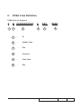
II.
PCBA Code Definition
PCBA Code for Projector
A B XXXXXXXXXXX
1
2
3
1
:
ID
2
:
Vendor Code
3
:
P/N
4
:
Revision
5
:
Date Code
6
:
S/N
C
XXX
4
5
EEEE
6
HD25/HD25LV/HD25e
Confidential
18