1
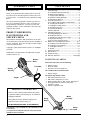
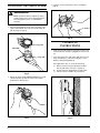
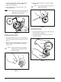
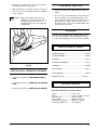
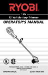
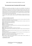
MODEL
140r
CORDLESS TRIMMER
OPERATOR'S
MANUAL
WARNING
Never operate the trimmer without the string
guard installed. If the unit is operated without
the string guard in place, you will void the
warranty.
IMPORTANT MANUAL
DO NOT THROW AWAY
1
INTRODUCTION
THANK YOU
CONTENTS
I.
Thank you for purchasing this quality product. This modern power tool has been designed to provide many hours
of useful service. You will find it to be a great labor-saving
device.
This manual has been prepared to provide you with common sense operating instructions and to ensure that you
will get maximum satisfaction. To keep your unit in top
operating condition, use the maintenance and service procedures in this manual.
II.
III.
PRODUCT REFERENCES,
ILLUSTRATIONS AND
SPECIFICATIONS
All information, illustrations and specifications in this manual are based on the latest product information available at
the time of printing. We reserve the right to make changes
at any time without notice.
Copyright © 1993 Ryobi Outdoor Products, Inc. All Rights
Reserved.
Bump Knob™ and Monoflail® are trademarks of Ryobi
Outdoor Products, Inc.
Battery
Door
IV.
V.
VI.
VII.
VIII.
Safety Warnings ......................................................3-4
A. Pre-Operational Safety Warnings ..........................3
B. Battery Safety Warnings ........................................3
C. Charger Safety Warnings........................................3
D. Operational Safety Warnings ..................................4
E. Other Safety Warnings ............................................4
Assembly Instructions..............................................5-7
A. Assembling and Mounting the Wall Station ..........5
B.. Installing the D-Handle ..........................................5
C. Installing the String Guard ......................................6
D. Charging Instructions ..........................................6-7
E. Removing the Battery ............................................7
F. Battery Disposal ......................................................7
Operating Instructions..............................................8-9
A. Starting/Stopping the Trimmer................................8
B. Holding the Trimmer ..............................................8
C. Adjusting the Trimming Line Length ......................8
D. Decorative Trimming ..............................................9
E. Tips for Best Trimming Results ..............................9
Maintenance and Repair Instructions ....................9-11
A. Installing a New Trimming Line..........................9-10
B. Installing a Prewound Reel ..................................11
C. Cleaning the Trimmer............................................11
D. Storage ................................................................11
Replacement Parts ....................................................11
Specifications ............................................................11
Troubleshooting ........................................................12
Warranty Statement ....................................Back page
CONTENTS OF CARTON
This unit should consist of the following:
D-Handle
Battery
Housing
1. Battery housing
2. Motor assembly
3. Aluminum outer housing (boom)
The cardboard insert should contain:
1. Battery charger
The plastic bag should contain:
Trigger
1.
2.
3.
4.
5.
6.
Wall station with three screws
Wall station clamp with one screw
Black D-handle with one bolt, washer and wing nut
String guard with two washers and screws
Operator's manual
Owner's registration card
SERVICE INFORMATION
Service on this unit both within and after the warranty period should be performed only by an authorized
and approved dealer.
Dial 1-800-345-8746 to obtain the listing of the
authorized service dealer nearest you.
String
Guard
Motor
Assembly
DO NOT RETURN THE UNIT TO THE RETAILER.
THIS PRODUCT IS COVERED BY ONE OR MORE OF THE
US PATENTS:
4,779,405;4,651,422;4,505,040;4,463,498; 4,223,441;2,125,668;
OTHER PATENTS PENDING.
2
Bump
Head
BATTERY WARNINGS
SAFETY WARNINGS
IMPORTANT SAFETY
INSTRUCTIONS —
SAVE THESE
INSTRUCTIONS !
THE PURPOSE OF SAFETY SYMBOLS IS TO ATTRACT
YOUR ATTENTION TO POSSIBLE DANGERS. THE
SAFETY SYMBOLS, AND THE EXPLANATIONS WITH
THEM, DESERVE YOUR CAREFUL ATTENTION AND
UNDERSTANDING. THE SAFETY WARNINGS DO NOT
BY THEMSELVES ELIMINATE ANY DANGER. THE INSTRUCTIONS OR WARNINGS THEY GIVE ARE NOT
SUBSTITUTES FOR PROPER ACCIDENT PREVENTION
MEASURES.
SYMBOL
MEANING
WARNING:
Failure to obey a safety
warning can result in injury
to yourself and others.
NOTE:
1. Battery units do not have to be plugged into an electrical outlet, therefore they are always in operating
condition. Be aware of possible hazards when you are
not using your battery unit.
2. AVOID UNINTENTIONAL STARTING—Don't carry the
unit with your finger on the switch.
3. USE ONLY THE CHARGER PROVIDED WITH YOUR
BATTERY UNIT. Do not substitute any other charger.
Use of another charger could cause batteries to
explode, causing serious injury.
4. DO NOT PLACE BATTERY UNITS OR THEIR BATTERIES NEAR FIRE OR HEAT. They may explode.
5. DO NOT CHARGE BATTERY UNIT IN DAMP OR WET
LOCATIONS.
6. For optimum performance, your battery unit should be
charged in a location where the temperature is more
than 50° F (10° C) but less than 100° F (37° C).
(See "Battery and Charging Tips for Maximum Performance" on page 4).
7. DO NOT dissassemble the battery housing. Return the
unit to your authorized service dealer for service or
repair.
Advises you of information or instructions
vital to the operation or maintenance of the
equipment.
CHARGER WARNINGS
1. Before using the battery charger, read all instructions
and cautionary markings in this manual on the battery
charger and the unit using the battery charger.
WARNING
Failure to obey a safety warning can result in
injury to yourself or to others. Always follow the
safety precautions to reduce the risk of fire,
electric shock and personal injury.
PRE-OPERATIONAL SAFETY
WARNINGS
1. Read and understand this operator's manual carefully
before using this unit. Be thoroughly familiar with the
proper use of your unit.
2. Thoroughly inspect your unit for loose or damaged
parts before each use. If there are any loose or damaged parts, perform the needed adjustments or
repairs before starting your unit.
2. To reduce the risk of injury, charge only sealed lead
acid rechargeable batteries. Other types of batteries
may burst, causing personal injury and damage.
3. Do not expose charger to rain or snow.
4. To reduce the risk of damage to the charger body and
cord, pull the charger body rather than the cord when
disconnecting the charger.
5. Make sure the cord is located so that it will not be
stepped on, tripped over, or otherwise subject to
damage or stress.
6. An extension cord should not be used unless absolutely necessary. Use of improper extension cords
could result in risk of fire and electric shock. If an
extension cord must be used, make sure:
a. The pins on the plug of the extension cord are the
same number, size and shape as those of the
charger.
b. The extension cord is properly wired and in good
electrical condition; and
c. The wire size is large enough for AC ampere rating
of the charger as specified below.
3. Keep all bystanders, especially children, at least
30 feet (10 m) away from the work area.
4. Carefully inspect the areas to be cut. Remove all
debris that could become entangled in the string.
Also remove any objects that could be thrown.
AWG Size of Cord, Feet
FEET
25
50
100
150
AWG
18
18
18
16
3
CHARGER WARNINGS
(continued)
7. DO NOT OPERATE CHARGER WITH A DAMAGED
CORD OR PLUG. If the cord or plug is damaged,
replace the charger.
8. Do not operate the charger if it has received a sharp
blow, been dropped, or damaged in any way. If the
charger case is damaged, replace the charger.
9. Do not disassemble the charger. The charger is not
serviceable; disassembly may result in a risk of electric shock or fire.
10. To reduce the risk of electric shock, unplug the charger from the outlet before attempting any maintenance
or cleaning.
11. Do not use charger outdoors.
OPERATIONAL SAFETY
WARNINGS
1. To reduce the risk of injury to yourself and others,
never operate the unit without the string guard in place.
2. Wear safety glasses or goggles at all times when
operating this unit.
3. Dress properly. Do not wear loose clothing or jewelry.
They can be caught in moving parts. Use rubber gloves
and substantial footwear when working
outdoors.
4. Keep hands, face, feet and long hair away from all
moving parts.
5. Do not attempt to touch or stop the string while it is
rotating.
6. Always hold the unit with both hands during operation.
Keep a firm grip on both the front and rear handles or
grips.
7. If you strike or become entangled with a foreign object,
stop the motor immediately and check for damage.
Repair any damage before further operation is
attempted. Do not operate the unit with loose or
damaged parts.
8. DO NOT FORCE THE UNIT—It will do the job better and
with less likelihood of a risk of injury working at the rate
for which it was designed.
9. Use the right tool. Do not use your unit for any job
except that for which it is intended.
10. Do not overreach. Keep proper footing and balance at
all times.
11. Always remain alert. To prevent injury to yourself and
others, do not operate your unit if you are fatigued or on
medication.
12. Do not extend the trimming line length beyond the
length specified in this manual.
4
OTHER SAFETY WARNINGS
1. Keep your unit in good working condition. Only your
authorized service dealer should perform any repair or
maintenance procedures that are not described in this
manual.
2. Use only original equipment manufacturer's
replacement parts when servicing this unit. These
parts are available from your authorized service dealer.
The use of non-standard parts, or other accessories or
attachments not designed for this unit, could result in
serious injury to the user and/or damage to the unit.
3. Never use metal-reinforced line or monofilament line
that is not specifically designed for use with your
model. This model uses 0.06 inch (1.6 mm)
monofilament line.
4. STORE UNIT INDOORS - When not in use, the unit
should be stored placed on the wall station in the
charging mode, which should be located in a cool, dry
and high place - out of the reach of children.
BATTERY AND CHARGER TIPS
FOR MAXIMUM PERFORMANCE
1. Your unit should be stored and charged at
temperatures between 100° F (38° C) and 50° F (10° C).
2. Batteries stored for long periods of time above 100° F
(38° C) will experience reduced life.
3. Cold temperatures will not affect the life of your
battery.
4. The unit should be stored on the charging station in
the charging mode.
5. Temperature effects on battery charging:
a)
100° F (38° C) to 50° F (10° C) - The battery will
be fully charged within 24 hours.
b)
50° F (10° C) to 40° F (4° C) - The battery will
require up to 48 hours to reach full charge.
c)
Below 40° F (4° C) - The battery will not reach full
charge.
d)
Reduced unit run time will be experienced when
the battery is not fully charged.
ASSEMBLY
INSTRUCTIONS
2. Mount the wall station to a wall stud (Fig. 2). Secure
the wall stud with the three screws provided.
NOTE: Strong mounting is important because
an inadequately mounted wall station
could drop to the floor and cause injury
or damage the trimmer.
ASSEMBLING AND MOUNTING
THE WALL STATION
Wall Stud
1. Push the barrel connector of the charger plug into the
slot of the wall station. Make sure the connector is
secure and inserted correctly into the slot shown (see
inset in Fig. 1).
2. Slide the clamp into the slot provided. Install screw
(Fig. 1).
Fig. 2
INSTALLING THE D-HANDLE
1. Push the D-handle down over the boom (Fig. 3).
2. Install and tighten the bolt, washer, and wing nut.
Fig. 1
Fig. 3
5
INSTALLING THE STRING GUARD
3. Install the screws and washers with a screwdriver
(Fig. 6).
WARNING
Never operate the trimmer without the string
guard installed. If the unit is operated without
the string guard in place, you will void the
warranty.
1. Place the string guard onto the motor assembly. Line
up the small tab with the small slot and the large tab
with the large slot (Fig. 4).
Small Slot
Fig. 6
CHARGING
INSTRUCTIONS
Large Slot
Small Tab
1. Make sure the wall station is fastened securely to the
wall stud and the charger is plugged into the wall outlet.
Large Tab
2. Insert the unit into the wall station and make sure it is
firmly seated (Fig. 7). When the red light is on, the
battery is being charged (Fig. 8).
If the light fails to turn on, check the following:
a)
Fig. 4
b)
c)
Barrel connector has been properly installed
into the wall station (see Fig. 1 on page 5).
Charger has been plugged into the wall outlet.
Trimmer is firmly seated in the wall station.
2. Rotate the string guard counterclockwise (to the left)
until the tabs line up with the screw holes and the
guard locks in place (Fig. 5).
Fig. 5
6
Fig. 7
Charging
Indicator
Light
REMOVING THE BATTERY
This unit is equipped with a sealed lead acid battery. When
the battery needs to be replaced, use the following procedure and refer to Fig. 10.
1. To remove the existing battery:
a)
b)
c)
d)
Remove the screw with a Torx® screwdriver
Lift off the battery door
Pull out the battery
Disconnect the wires from the battery.
2. To install the new battery:
a)
Fig. 8
3. Charge the unit for a minimum of 36 hours before
the first use.
4. The battery should be charged for a minimum of 24
hours between each use. The trimmer's operating
time and the life of the battery will be shortened if this
procedure is not followed.
5. This unit is designed so that the battery cannot be
overcharged. Always place the unit back on the wall
station immediately after use.
b)
c)
d)
Connect the black wire to the negative terminal
and the red wire to the positive terminal.
Slide the battery into the slots in the housing.
Be careful not to pinch the wires.
Hook the back end of the battery door to the
housing. The two ribs should interlock (see inset).
Hold the door in place and install the screw.
Door
Black Wire
Battery
6. The unit should be stored at temperatures between
50° F (10° C) and 100° F (37° C).
Red Wire
Screw
7. Batteries emit explosive gases while being charged.
Do not obstruct the vents on the battery case (Fig. 9).
WARNING
Do not smoke while charging or operating the
unit. Keep unit away from open flames.
Fig. 10
WARNING
• Do not incinerate or mutilate battery.
Batteries contain hazardous chemicals.
Dispose of properly.
• Do not allow metal objects to contact the
battery terminals. Metal objects can short
the battery terminals and cause permanent
battery damage.
BATTERY DISPOSAL
Fig. 9
Take the used battery to a local authorized service dealer.
Do not dispose of the battery yourself.
7
OPERATING
INSTRUCTIONS
HOLDING THE TRIMMER
1. Hold the trimmer as shown in Figure 12.
This trimmer has been designed and built to withstand normal use. It will provide many hours of service provided the
following operating instructions are closely adhered to.
WARNING
Always wear eye, hearing, foot and body
protection to reduce the risk of injury when
operating this unit.
STARTING / STOPPING
THE TRIMMER
1. Push in the safety release switch (Fig. 11).
2. Squeeze the trigger to start the trimmer. Release the
trigger to stop (Fig. 11).
Fig. 12
ADJUSTING THE TRIMMING
LINE LENGTH
1. Your trimmer is equipped with a Bump Head, which
allows the operator to release more trimming line
without stopping the motor. As the line becomes
frayed or worn, additional line can be released by
lightly tapping the Bump Head on the ground (Fig. 13)
while operating the trimmer at high speed.
1
2
Fig. 11
WARNING
Do not invert the trimmer until the cutting head
has completely stopped rotating.
Fig. 13
Each time the head is bumped, approximately 1 in
(25.4 mm) of trimming line is released. A blade in the string
guard will cut the line if excess line is released.
For best results, tap the head on bare ground or hard soil.
If line release is attempted in tall grass, the motor may
overheat. Always keep the trimming line fully extended.
Line release becomes more difficult as the cutting line
becomes shorter.
8
DECORATIVE TRIMMING
MAINTENANCE AND
REPAIR INSTRUCTIONS
1. Decorative trimming is accomplished by removing all
vegetation around trees, posts, fences, etc. Use a 30degree angle when trimming with this method (Fig. 14).
INSTALLING A NEW
TRIMMING LINE
The trimming line may be replaced by two different methods — rewinding the existing reel or installing a convenient
prewound reel.
Rewinding the Existing Reel
To rewind the existing reel you must:
1.
2.
3.
4.
Check for the correct line size
Remove the existing inner reel
Wind the existing reel with the new line
Reinstall the existing reel.
Fig. 14
The Correct Line to Use
TIPS FOR BEST TRIMMING RESULTS
WARNING
1. Hold the cutting line parallel to the ground, and the
cutting head will be at the correct angle.
NOTE: Do not rest the Bump Head on the ground.
Always use genuine Monoflail® replacement
line. Do not use metal-reinforced line.
2. DO NOT FORCE THE UNIT. Allow the very tip of the
line to do the cutting (especially along walls). Cutting
with more than the tip will reduce cutting efficiency
and may overload the motor.
It is very important to use the correct size line. Line with a
diameter of 0.065 inches (1.65 mm) must be used. The
motor may overheat or be damaged if you use a larger
line.
3. Grass over eight (8) inches (200 mm) should be cut by
working from top to the bottom in small increments to
avoid premature line wear or motor drag.
Removing the Existing Reel
4. Whenever possible, cut to your left. When cutting to
the left, the unit's cutting efficiency is improved slightly. Also, the clippings are thrown away from the operator.
1. Squeeze the tabs on the Bump Head cover and
remove the cover (see inset in Fig. 15).
2.
Remove the existing inner reel and spring (Fig. 15).
Cover
5. Slowly move the trimmer into and out of the area being
cut, maintaining the trimmer at the desired cutting
height. This can be either a forward-backward or sideto-side motion. Maintain top speed for best cutting.
Tab
6. Trim only when grass and weeds are dry.
7. The life of your cutting line is dependent upon following
the previously stated trimming techniques, as well as
what is being cut, and where the cutting is being done.
For example, the line will wear faster when trimming
against a foundation wall as opposed to trimming
around a tree. Some line breakage will occur from:
•
•
•
•
Entanglement with foreign matter
Normal line fatigue
Attempting to cut thick, stalky weeds in excess of
the unit's capability.
Forcing the line into objects such as walls or
fenceposts
Inner
Reel /
Bump Knob
Spring
Outer
Spool
Fig. 15
9
3. Check the indexing teeth on the inner reel and outer
spool for wear (Fig. 16). If necessary, deburr or
replace the spool and reel.
4. Use a clean cloth to clean the inner surface of the
outer spool (Fig. 16).
3. Push the end of the line into one of the two holding
slots (Fig. 18).
NOTE:
Do not wind the line past the point indicated on the inner reel.
NOTE: Always clean the the inner reel and outer
spool. Do not remove the bolt from the
center shaft of the outer spool.
Indexing
Teeth
Fig. 18
Reinstalling the Reel
Fig. 16
Winding the Existing Reel
1. Place the spring back on the center shaft of the outer
spool (See Fig. 15 on page 9).
2. Insert the end of the line through the eyelet in the
outer spool (Fig. 19).
1. Take approximately 20 ft (5.1 m) of new trimming line,
insert one end of the line into the hole in the inner reel
(Fig. 17).
2. Wind the line, in even and tight layers, onto the reel
(Fig. 17). Wind the line in the direction indicated on
the inner reel.
NOTE:
Failure to wind the line in the direction
indicated will cause the Bump Head to
operate incorrectly.
Fig. 19
Fig. 17
10
3. Grasp the end and pull firmly to release the line from
the holding slot in the reel (Fig. 20).
4. While pushing the inner reel back into the outer spool,
snap on the cover of the Bump Head. Line installation
is now complete.
NOTE:
Make sure the tabs on the cover are
snapped on completely with the slots on
the Bump Head. If the cover is not
installed properly, it can come apart during operation.
CLEANING THE UNIT
1. Keep the air vents free of obstructions (See Fig. 9 on
page 7).
2. Do not use any strong detergents on the plastic housing or the handle. They can be damaged by certain
household cleaners that contain aromatic oils such as
pine and lemon, and by solvents such as kerosene.
Moisture can also cause a shock hazard. Wipe off any
moisture with a soft cloth.
STORAGE
Clean the unit thoroughly before storing it. Always store
the unit on the wall station, which should be located in a
cool, dry, well-ventilated area, out of the reach of children.
REPLACEMENT PARTS
PREWOUND REEL ....................................................180292
GUARD ASSEMBLY ..................................................180408
D-HANDLE ................................................................145819
D-HANDLE HARDWARE ..........................................153523
Fig. 20
CHARGER ................................................................180409
WALL STATION..........................................................180412
INSTALLING A PREWOUND REEL
1. Follow the instructions in THE CORRECT LINE TO
USE.
2. Follow the instructions in REMOVING THE EXISTING
REEL.
6-VOLT BATTERY ......................................................180410
BATTERY DOOR ..................................................180411
SPECIFICATIONS
3. Follow the instructions in REINSTALLING THE REEL.
BATTERY, MOTOR & CUTTING HEAD
Motor ........................................6 Volts - DC
Battery ......................................6 Volts - Sealed Lead Acid
Outer Housing ..........................Aluminum Tube
Cutting Head ............................Bump Line Releaser
Trimming Line Diameter............0.065 in. (1.65 mm)
Cutting Path Diameter ..............8 in. (203 mm)
11
TROUBLESHOOTING
POSSIBLE CAUSE AND CHECK
POSSIBLE REMEDY
BATTERY WILL NOT CHARGE
Barrel Connector Has Not Been Installed Properly ....................Insert the barrel connector as shown in Fig. 1 on page 5.
Charger is Not Plugged into the Wall Outlet ..............................Plug charger into the wall outlet.
Charger Is Not Firmly Seated in the Wall Station ......................Check the position of the unit in the wall station.
MOTOR OPERATES SLOWLY OR WILL NOT OPERATE
Battery Is Not Charged
Charge the battery for 36 hours before the first use; 24 hours
minimum between each use.
Foreign Matter is Caught Between Bump Head and
Motor Housing ............................................................................Remove string, plastic or other foreign matter.
CUTTING HEAD WILL NOT ADVANCE LINE
Cutting Head Out of Line............................................................Refill with genuine replacement cutting line.
Bump Knob/Inner Reel Bound Up..............................................Replace Bump Knob/inner reel.
Outer Spool Dirty ........................................................................Clean outer spool.
Indexing Teeth Worn or Burred ..................................................Replace inner reel and outer spool.
Line Welded ................................................................................Disassemble, remove the welded section and rewind line.
Line Twisted When Refilled ........................................................Disassemble and rewind reel.
Not Enough Line Exposed
Push the Bump Knob until the line is extended to the edge of
the guard.
If the above remedies do not work, take the unit to your authorized service dealer for
service or repair. Do not return the unit to the retailer.
Operator's Manual Part No. 180407
Printed in U.S.A.
12
Rev. C
6/96