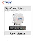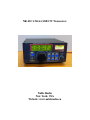
1
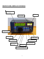
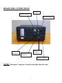
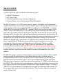
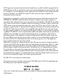
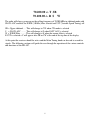
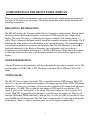
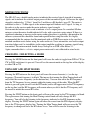
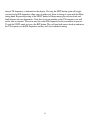
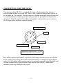
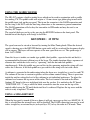
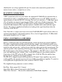
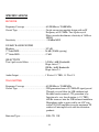
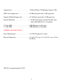
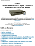
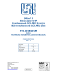
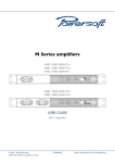
NR-4SC 4 Meter SSB/CW Transceiver
Noble Radio
New York, USA
Website: www.nobleradio.eu
TABLE OF CONTENTS
Introduction ………………………………………………………… 3
Front Panel Display/Controls ……………………………………… 4
Rear Panel Connections ……………………………………………. 5
NR-4SC Setup ……………………………………………………… 6
Components of the Front Panel Display …………………………… 9
Meter Functions ……………………………………………………. 11
Changing / Selecting a Mode ……………………………………… 11
Using RIT and SPLIT Modes ………………………………………. 11
Transmitting with the NR-4SC ……………………………………... 13
Using the Iambic Keyer …………………………………………….. 14
Using a Straight Key ………………………………………………... 14
IF Output Connection …………………………………………….… 15
Using an External Amplifier ……………………………………...... 15
Specifications ……………………………………………………… 16
2
INTRODUCTION
Congratulations on the purchase of your NR-4SC. The NR-4SC is a simple to use 10 Watt
(minimum) 4 Meter SSB/CW transceiver. The radio operates USB and CW. The NR-4SC uses
a single conversion design with an IF frequency of 10.7 MHz. Front end bandpass filters limit
out of band signals into the RF Preamp stage. A double balanced diode ring mixer provides
good strong signal handling capability. There are two 8 pole crystal filters following the mixer
which are designed for 3.0 kHz and 500 Hz -6dB bandwidths. The 3 kHz filter allows for good
SSB voice fidelity while the 500 Hz filter provides good adjacent channel rejection on CW.
Either filter can be selected in both modes. Two IF amplifier stages and fast attack AGC
provide good receiver sensitivity while leveling the audio output on strong signals. AGC action
starts at approximately a -120 dBm input signal level. The local oscillator is derived from a
DDS/PLL circuit providing a high degree of stability and low noise. A high stability 107.374
MHz reference oscillator is used for all local oscillator generation. The high frequency provides
low DDS spurious output.
Other features of the NR-4SC include RIT (Receiver Incremental Tuning) and SPLIT mode
functions as well as a built in Iambic Keyer for CW. The AGC rate has a FAST and SLOW
speed to suit operator preference.
3
FRONT PANEL DISPLAY/CONTROLS
LCD Frequency &
Status Display
RIT Select
S / Power Meter
Key Speed Change
Headphone Jack
Volume Control
Main Tuning Knob
Wide or Narrow
Filter Select
SPLIT Mode Select
AGC Speed Select
MODE Select
Variable Speed Tuning Select
4
REAR PANEL CONNECTIONS
IF Output
Antenna Connector
External Amp Key
DC Power
Connector
Keyer Paddle
Connector
External Speaker
Connector
Interface Connector
NOTE:
Microphone Connector is located on the right side of the radio
5
NR-4SC SETUP
Carefully unpack the radio and check for the following items:
1)
2)
3)
4)
NR-4SC Transceiver
DC Power Cable
External Amplifier keying connector with pigtails
If ordered there will also be the optional Hand Microphone
The NR-4SC requires a 13.8 VDC power source to operate. It should be well regulated and
capable of delivering at least 4 amps of current. The DC power cable must be connected to the
output terminals of the power supply. The RED wire connects to the POSITIVE (+) terminal
and the BLACK wire to the NEGATIVE (-) terminal. Check to be sure that the power switch,
which is on the VOLUME control is in the OFF position before connecting the cable to the
radio. The 2 pin circular connector on the power cable must be inserted into the power jack on
the back panel of the radio (refer to the back panel photo for the location of this connector). Be
sure to observe the polarity pin on the connector and turn the connector hood clockwise about ½
turn until you feel a click. Do not force the hood past this point or damage to the connector
could result. The NR-4SC is protected by a 5 Amp Fuse that is located inside the radio on the
Power Amplifier Board. The board is located on the rear panel and may be accessed by
removing the 4 top cover screws and lifting the cover off the radio. The fuse is readily
accessible right at the top of the unit. A label on the rear panel indicates the approximate
location of the fuse inside the unit. IMPORTANT: Only replace a blown fuse with a 5 Amp
fuse 61NM type fast acting fuse. A higher amperage fuse can cause damage to the radio. If a
replaced fuse blows again then the radio should be serviced to determine the cause of the
problem.
The NR-4SC requires a properly matched antenna system for the best results in both reception
and transmission. Resonant antennas or broadband antennas using an antenna tuner are
recommended for the best results. An antenna such as a multi-element yagi will add gain to
both the received and transmitted signal as well as provide directionality to the signal path.
Whichever type of antenna is used, it must present no more than a 2:1 SWR to the transmitter in
the NR-4SC. This not only insures maximum power transfer to the antenna but also protects the
final output transistors in the transmitter and guarantees output amplifier stability. A standard
UHF (PL-259) coax connector is provided on the rear panel for connection to the antenna (see
the rear panel photo for the location of this connector). The transmitter output is designed to
match a 50 ohm load.
6
If CW operation is planned using the internal iambic keyer a paddle should be plugged into the
PADDLE jack on the rear panel of the radio (refer to back panel photo for location of this jack).
If a straight key is to be used then it can be connected to the DASH side of the paddle jack and
the keyer should be set to MANUAL mode. See the section on using a straight key for
instructions on how to do this.
If operation of an amplifier is planned the amplifier keying circuit should be connected to the
EXTERNAL AMP KEY connector on the rear panel. A mating 3 pin circular connector is
provided for this with pigtail wires for easy connection to the amplifier. The NR-4SC provides a
relay contact closure to key an amplifier. When the transmitter is keyed by either a push to talk
(PTT) closure on the mic connector or by a key closure for CW the relay will close to key the
amplilfier. Approximately 15 mS later RF will appear at the output of the antenna connector on
the NR-4SC. When the key or PTT is released the RF will stop buit the relay will stay closed
for approximately another 18 mS (keeping the RX muted) before it is released and the amplifier
is unkeyed. The NR-4SC can be setup for either QSK or non-QSK (semi break-in) operation. In
QSK the relay will follow every dot and dash fom the keyer or straight key with the above
described sequence. If the amplifier is capable of QSK operation then this mode can be used.
For non QSK operation the time that the radio is held in a receiver muted mode (and the amp
key relay will stay on) is determined by what ever the keyer speed is set to. The higher the
keyer speed the shorter the mute delay will be.
QSK mode is selected by a jumper inside the radio. The top cover must be removed and there
will be a small PCB on the top right wall of the radio (looking from the front). There is a small
jumper block on that board which sets the mode to QSK or semi break-in. If QSK is desired
then the jumper should be disconnected (that is the default way it is shipped from the factory).
If semi break-in is chosen then the jumper must be placed on the 2 pins on the board. The
computer will only read that jumper when the radio is first powered up. So the radio should be
turned off when the jumper is set and then turned on to effect the change. Replace the cover of
the unit after changing the jumper and verifying proper operation.
The NR-4SC is now ready for an initial check.
Turn on the main power with the switch on the VOLUME control. The LCD should light and
the following message should be displayed:
NOBLE RADIO
REV B (C) 2014
After a few seconds that message will be erased and the following standard display format
should appear:
7
70.200.00 <- T SB
70.200.00 <- R S W
The radio will always power up on the calling frequency of 70.200 MHz in sideband mode with
SLOW AGC enabled, the WIDE (3.0 kHz) filter selected and VST (Variable Speed Tuning) off.
SB = Upper sideband …. This will change to CW when CW mode is selected
S = SLOW AGC ……. This will change to F when FAST AGC is selected
W = WIDE Filter …….. This will change to N when the narrow filter is selected
If VST is selected a V will appear after SB or CW at the end of the top line of the display
At this point the receiver should be active and the Main Tuning knob can be used to search for
signals. The following sections will guide the user through the operation of the various controls
and functions of the NR-4SC.
8
COMPONENTS OF THE FRONT PANEL DISPLAY
There are several fields of information on the front panel display which inform the operator of
the status of the radio at any given time. The display information can be broken down into the
following components:
FREQUENCY INFORMATION:
The NR-4SC displays the Transmit and the Receive frequencies simultaneously. The top line of
the display shows the Transmit frequency to the nearest 10 Hz using the first 7 digits of the
display. The arrow character (<-) following the frequency indicates that transmit tuning is
active. That is, whenever the tuning knob is turned the transmitter frequency will change. The T
following the arrow indicates that this number is the transmit frequency. The same information
is displayed for the Receiver frequency on the bottom line. The only difference is that an R is
displayed indicating it is the Received frequency. In certain modes only one of the two
frequencies may be changing with tuning (i.e. SPLIT or RIT modes). When one of these modes
is active the arrow character next to the frequency which is not active will not appear on the
display.
MODE INFORMATION:
After the T on the top line the display will show the mode that the radio is currently set for. The
possible modes are SSB (USB) or CW. The display will show SB for SSB and CW for CW
mode.
TUNING RATE:
The NR-4SC has two tuning rate modes. This is controlled with the VST function. With VST
off (no V at the end of the top line of the display) the tuning step size will be 10 Hz. The tuning
encoder has 128 lines per revolution so that means one revolution of the tuning knob will move
the frequency 1.28 kHz. This is useful for fine tuning an SSB signal or zero beating a CW
signal. It gives a very “analog feel” to the tuning. For general tuning it is best to use the VST
feature. With VST engaged the faster the knob is spun the larger the tuning step. The rate will
run from 10 Hz then 100 Hz and finally 1 kHz per step. At a rate of 1 kHz it is possible to cover
over 100 kHz in a full dial rotation. The VST mode is indicated by a V at the end of the top line
of the display. There is a label on the front panel next to the display to indicate this.
9
AGC SELECTION:
The NR-4SC provides two AGC speeds that are selectable from the front panel AGC switch.
The default on power up is SLOW AGC and is indicated by the S on the display next to the
receive frequency (bottom display line). There is a label on the front panel under the display to
indicate this. The speed can be change to FAST by pressing the AGC button on the front panel.
The display indicator will change to an F. Repeated pressing of this key will toggle the speeds
between slow and fast.
FILTER SELECTION:
The NR-4SC comes standard with two 8 pole crystal filters installed. One is a 3 kHz wide filter
designed for SSB and general CW use. The second is a 500 Hz wide filter for CW use in
crowded band conditions to isolate the desired signal. The default filter on power up is the 3
kHz (WIDE) filter and is indicated on the front panel display with a W on the display at the end
of the line showing the received frequency (bottom line). There is a label on the front panel
under the display to indicate this. The filter can be changed by pressing the FILT key on the
front panel. Repeated pressing of the switch will cause the unit to toggle between the wide and
narrow filters.
This covers the information that is available to the user on the display. The remaining functions
will be covered in the following sections
10
METER FUNCTIONS
The NR-4SC uses a backlit analog meter to indicate the received signal strength of incoming
signals and to indicate the relative output power of the transmitted signal. On receive the signal
strength is indicated as “S Units” from 0 to 9 and then as dB (decibels) over S9. The meter is
calibrated so that a -72 dBm signal at the antenna input will indicate an S9 signal. As long as
the radio is in the receive mode the meter indicates signal strength.
On transmit the bottom scale is used to indicate relative output power. In a matched 50 ohm
antenna system the meter should indicate full scale with a constant carrier output. If there is a
significant reduction or increase in the meter reading then there is probably a mismatch in the
antenna system and this should be found and repaired before using the radio. It is highly
recommended that the antenna load be monitored with an SWR/Power meter to be sure that a
matched condition exists before using the radio on the air. Sever mismatches can lead to output
transistor failure and / or instabilities in the output amplifier resulting in spurious signals being
transmitted. The antenna match should always be kept to an SWR value below 2:1.
Again, remember this is a relative output power meter and is not calibrated to actual watts.
CHANGING / SELECTING A MODE
Pressing the MODE button on the front panel will cause the radio to toggle from SSB to CW (or
CW to SSB) each time it is pressed. You will see the current mode on the top line of the display
as either SB or CW.
USING RIT AND SPLIT MODES
Pressing the RIT button on the front panel will cause the arrow character (<-) on the top
frequency (Transmit frequency) to blank. That means that turning the Main Tuning knob will
only affect the receive frequency (on the bottom line). You can now offset the RX frequency
from the TX frequency by any amount within the tuning range of the radio. When the RIT
button is pressed again you will exit the RIT mode (arrow will appear next to the TX frequency
on the top line) and the RX frequency will remain where you left it but the TX frequency will
be moved to match the current RX value.
Pressing the SPLIT button on the front panel will cause the arrow by the TX frequency to blank.
This again means that turning the Main Tuning control knob will only change the RX
frequency. You will also be listening to the frequency indicated as the RX frequency on the
display. Pressing the SPLIT button again will move the arrow from the RX frequency display
line to the TX frequency display line. Turning the Main Tuning knob will now cause the TX
frequency to change and leave the RX where it was. You will also now be listening to the
11
current TX frequency as indicated on the display. Pressing the SPIT button again will toggle
you back to the RX frequency where you can either just listen or change it again with the Main
tuning knob. Repeated pressing of the SPLIT buttin will keep moving the receiver back and
forth between the two frequencies. Note that if you are pointing to the TX frequency you will
not be able to transmit. The arrow must be on the RX frequency for the transmitter to operate.
To exit the SPLIT mode just press the RIT button. This will turn both arrows back on and move
the TX frequency to the RX frequency and they will stay locked for tuning.
12
TRANSMITTING WITH THE NR-4SC
Transmitting with the NR-4SC is very simple. You tune to the desired transmit frequency,
select the mode and then use the mic PTT (Push to Talk) switch for SSB operation or press the
key or paddle for CW operation. The Mic connector is located on the right side of the radio and
it is recommended that a right angle connector be used with the microphone to minimize the
strain on the cable. The optional Noble Radio microphone is sold with that type of connector.
See the figure below for the mic connector wiring:
PIN 8 – MIC AUDIO
KEY
PIN 7 - GND
PIN 5 – RX AUDIO
PIN 6 – PTT
Microphone Connector Wiring – Viewed
from the front of the Chassis Connector
Pin 5 of the connector (RX Audio) is a fixed level audio output from the receiver (not affected
by the volume control setting) that can be used for interfacing to a computer to operate digital
modes. It is AC coupled to the connector pin but a transformer or optical isolator should be used
to couple both the receiver and transmitter audio from the radio to the PC sound card to
minimize ground loops and hum on the signals.
13
USING THE IAMBIC KEYER
The NR-4SC contains a built in iambic keyer which can be used in conjunction with a paddle
for sending CW. The paddle cable will require a 3.5 mm stereo type phone plug to mate with
the paddle input jack on the rear panel. The tip on the connector is the DASH connection and
the first ring is the DOT with the final ring connection as the common or ground connection.
The DASH connection will also key the transmitter in SSB mode and may be used as an
auxiliary PTT input.
The speed of the keyer can be set by pressing the KEYSPD button on the front panel. The
bottom line of the display will change to look like:
KEYSPEED : 25 WPM
The speed can now be raised or lowered by turning the Main Tuning knob. When the desired
speed is showing press the KEYSPD button again and it will be saved and the frequency display
will re-appear. The keyer will now operate at the new speed that was set. The speed range is
from 5 to 35 WPM.
Since this keyer is iambic, an iambic type paddle (dual paddles, separate for dot and dash) is
recommended for the most efficient use of the keyer. The iambic function allows sequences of
alternate dots and dashes to be sent by “squeezing” both the dot and dash paddles
simultaneously. If the dot paddle was pressed first in the squeezing motion the string will start
with a dot. Likewise, if the dash paddle was pressed first the string will start with a dash.
A sidetone is generated in the audio output when the keyer or a straight key is used to send CW.
The volume of the tone is constant regardless of the volume control setting. There is provision
inside the unit for setting the level of the sidetone to suit individual preference. To adjust the
sidetone level remove the top cover of the radio. The level control is located on the Main
(bottom) PC board at the rear right hand side near the speaker. It is marked on the PC board
“SIDETONE LVL”. Using a small flat blade screwdriver turn the screw on the top of the
control while keying the TX until the desired level is achieved. Replace the top cover and the
radio is ready to operate CW mode.
USING A STRAIGHT KEY
When the keyspeed is turned all the way down it will put a message up that says MANUAL. If
this is selected then the internal keyer will be disabled. The DASH connection can now be used
with a straight key or external keyer (or keyed by a PC) to key the radio in CW mode. There
14
should not be any voltage applied to this pin. It is meant to be connected to ground with a
contact closure such as a straight key or a relay.
IF OUTPUT CONNECTION
A BNC connection on the rear panel allows the wideband 10.7 MHz IF to be monitored by an
external device such as a spectrum analyzer or an SDR receiver set to 10.7 MHz to provide a
spectral display of what the NR-4SC is hearing. The levels are such that a -72 dBm input signal
(S9) will produce an output of approximately 0 dBm (1 mW into a 50 ohm termination). This
level may be excessive for input to an SDR receiver and may need to be reduced with an
external 50 ohm attenuator. Most spectrum analyzers should be able to deal with this signal
directly. The output is amplified and buffered so loading of the signal should not affect the
sensitivity of the NR-4SC.
Note: Since this is a single conversion receiver the 10.698 MHz BFO signal will be visible on a
spectrum output display at the tuned frequency. It has a level of approximately -28 dBm which
corresponds roughly to an S 3.5 signal.
USING AN EXTERNAL AMPLIFIER
There is a connector on the rear panel that provides a means for keying an external amplifier.
The radio is supplied with a mating connector that has “pigtail” wires attached to make it easy
to attach a custom cable for keying the external amplifier. The connector is wired to a reed relay
inside the radio and provides a contact closure when the radio is put into the transmit mode. The
software provides some sequencing of the keying to allow the T/R relays time to switch before
RF actually appears at the antenna connector. The sequence is: Mic PTT or key is closed, T/R
relay and Amp keying relay switches. After 15 mS the RF appears at the antenna connector.
Upon release of the PTT or key the RF is stopped. After 18 mS the T/R relay and the Amp
keying relay are switched to receive and Amp off.
The NR-4SC is shipped setup for QSK operation in CW mode. Some amplifiers may not be
usable in QSK or the operator may not wish to use QSK even without an amplifier. To switch to
a non QSK mode of operation refer to the section on “NR-4SC Setup”.
The Amplifier Keying connector is wired as follows:
Red Wire: Relay output (N.O. Contact)
Green Wire: Relay return (Connected to radio Ground)
White Wire: Not used … Reserved for connection to Noble Radio Amplifier
15
SPECIFICATIONS
RECEIVER:
Frequency Coverage ……………………… 69.900 Mhz to 70.400 MHz
Circuit Type ………………………………. Single conversion superhet design with an IF
Frequency of 10.7 MHz. Two 8 pole crystal
Filters provide the ultimate selectivity of 3 kHz or
500 Hz
Sensitivity ………………………………… -130 dBm MDS
DYAMIC RANGE FIGURES
Blocking ………………………………….. 107 dB
3rd Order IMD ……………………………. 96 dB (20 kHz spacing)
2nd Order IMD ……………………………. 87 dB
SELECTIVITY
Two 8 pole crystal filters ………………… 3.0 kHz (-6dB) Bandwidth
Shape factor 1.7
500 Hz (-6dB) Bandwidth
Shape factor 2.4
Audio Output …………………………….. 1 Watt at 1% THD, 1.5 W at 5%
TRANSMITTER:
Frequency Coverage ……………………… 69.900 Mhz to 70.400 MHz
Circuit Type ………………………………. SSB generation from a 10.7 MHz IF signal passed
Through a crystal filter for LSB sideband and
Residual carrier removal. CW generation is by
Injection of a very low distortion (< 1% THD)
650 Hz sinewave into the SSB balanced modulator
Microphone audio is processed by an AGC controlled VOGAD amplifier to create maximum TX
audio at all mic input levels with low distortion
products
Emission Types …………………………… SSB, CW J3E
16
Output Power ……………………………… 10 Watts PEP or CW Minimum (Typical 12W)
SSB Carrier Suppression ………………….. 48 dB below peak with a 1 kHz input tone
Opposite Sideband Suppression ………….. > 55 db below peak with a 1 kHz input tone
Spurious Radiation ……………………….. > -55 dBc for harmonic and non harmonic spurs
(Meets ETSI EN301 783-1 Standards)
3rd Order IMD ……………………………. -25dB Minimum at full output
5th Order IMD ……………………………. -52dB Minimum at full output
GENERAL SPECIFICATIONS
Power Requirements ……………………… 13.8VDC Regulated at 5 Amps
Physical Dimensions ……………………… 8.7 in W (22.1 cm) x 8.7 in D (22.1 cm) x 3.94 in
H (10 cm)
NR-4SC is manufactured in the USA
17