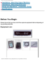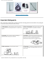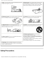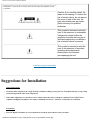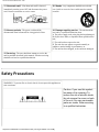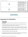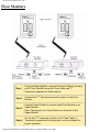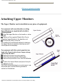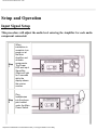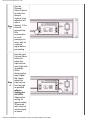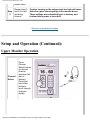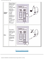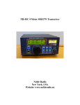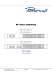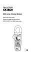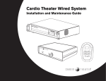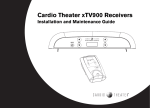
1
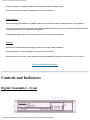
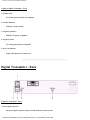
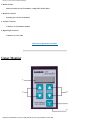
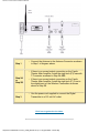
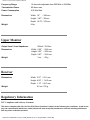
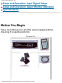
Wireless Cardio Theater Installation Manual
On-Line
Cardio Theater Wireless Digital Transmitter
Installation and Instruction Manual
Full installation instructions accompany your Cardio Theater equipment order. This On-Line version of our
Installation/Instruction Manual is included in our web site for your convenience. If you have any questions regarding
your installation that are not covered by this Manual or by our Troubleshooting Guide, please contact our Technical
Support Department:
Cardio Theater Inc.
Service Department
Toll-Free Telephone in the United States: 1-800-776-6695
International Telephone, dial code for United States, then: (503) 690-5464
E-mail: [email protected]
Table of Contents
(Click to jump to the page you want to see.)
Before you begin
Important Safeguards
Suggestions for Installation
Installation: Controls and Indicators - Digital Transmitter
Installation: Controls and Indicators - Monitors and
Receivers
Installation: System Connections: Digital Transmitter
Installation: Receiver Configurations
http://www.cardiotheater.com/CT_Install_Manual.htm (1 of 18) [4/13/2004 7:43:04 AM]
Wireless Cardio Theater Installation Manual
Installation: Attaching Upper Monitors
Installation: Attaching Receivers
Setup and Operation: Transmitter Setup
Specifications
Before You Begin
Please insure that you have all of the required equipment before disposing of
any packing materials.
Equipment List:
Wireless Digital Transmitter
Upper Monitors,
quantity as ordered
Power Cord,
quantity (1)
Receivers,
quantity as ordered
http://www.cardiotheater.com/CT_Install_Manual.htm (2 of 18) [4/13/2004 7:43:04 AM]
Plastic wire ties;
(4) for each Upper Monitor
Wireless Cardio Theater Installation Manual
Antenna,
(1) for each Transmitter
Coiled Cables;
(1) for each Upper Monitor
Power Adapter;
As ordered
Coax Cable;
(1) for each Floor Monitor
Click here to go back to the Index.
Important Safeguards
Please read all of these safeguards before operating the unit. Follow all warnings placed on the unit and adhere to the operating and
use instructions. Retain your manual for future reference.
1. Power sources - Connect the unit to a power source only of
the type described in the operating instructions or as marked on the
appliance.
2. Power cord protection - Route all power-supply cords
so that they are not walked on or pinched by items placed
upon or against
them.
3. Grounding - Take precautions so that the grounding or
polarization means of the unit are not defeated.
4. Ventilation - Position the unit so that its location does not
interfere with ventilation. To maintain good ventilation, do not
put items on or over the unit. Do not use the unit on a
cushioned surface that may block the ventilation openings.
5. Water and moisture - Do not locate the unit near
6. Temperature - The unit may not function properly if used
at extreme temperatures. The ideal temperature is 41oF (5oC)
to 87oF (30oC)
water.
http://www.cardiotheater.com/CT_Install_Manual.htm (3 of 18) [4/13/2004 7:43:04 AM]
Wireless Cardio Theater Installation Manual
7. Heat - The unit should be located away from heat sources such
as radiators, heat registers, stoves, etc
8. Electric shock - Care should be taken so that objects do
not fall and liquid is not spilled on the enclosure. If a metal
object, such as a hairpin or a needle, comes in contact with the
inside of this unit, a dangerous electric shock may result.
9. Enclosure removal - Never open the enclosure. If the internal
parts are accidentally touched, a serious shock may occur.
10. Cleaning - Do not use solvents such as alcohol; paint
thinner, etc. to clean the unit. Use a clean dry cloth.
11. Abnormal smell - If an abnormal smell is detected,
immediately turn the power OFF and disconnect the power cord.
Contact your dealer or service center.
12. Stands - Any component should be moved with care.
Quick or excessive force could cause the stand to overturn.
13. Nonuse periods - The power cord should be disconnected
when left unused for a long period of time.
14. Damage requiring service - The unit should be
serviced by a qualified technician when:
A. The power supply cord or the plug has been damaged;
B. Objects have fallen, or liquid has been spilled into the unit;
C. The unit has been exposed to rain;
D. The unit does not appear to operate normally or exhibits a
marked change in performance; or
E. The unit has been dropped, or the enclosure damaged.
15. Servicing - The user should not attempt to service the unit
beyond that described in this manual. All other servicing should be
referred to a qualified technician.
Safety Precautions
http://www.cardiotheater.com/CT_Install_Manual.htm (4 of 18) [4/13/2004 7:43:04 AM]
Wireless Cardio Theater Installation Manual
WARNING: To prevent fire or electric shock, do not expose this appliance to rain
or moisture.
Caution: If you see this symbol, be
aware of its meaning: To reduce the
risk of electric shock, do not remove
the cover or back of the unit. No
user-serviceable parts are inside.
Refer servicing to a qualified
technician.
This symbol is intended to alert the
user to the presence of uninsulated
"dangerous voltage" within the
product's enclosure that may be of
sufficient magnitude to constitute a
risk of electric shock to persons.
This symbol is intended to alert the
user to the presence of important
operating and maintenance
instructions in the literature
accompanying the unit.
Click here to go back to the Index.
Suggestions for Installation
General Suggestions
❍
Group the audio components in a single location to minimize cabling. Always place the Transmitter directly on top of amp
when stacking with the other audio components.
❍
If the audio components are stacked in a stereo cabinet, insure that there is adequate ventilation. The Cardio Theater
Amplifier and Digital Transmitter each require a minimum one inch (1") clearance on both sides for ventilation.
Transmitter:
❍
Place the Digital Transmitter in a well ventilated area with the front and back easily accessible.
http://www.cardiotheater.com/CT_Install_Manual.htm (5 of 18) [4/13/2004 7:43:04 AM]
Wireless Cardio Theater Installation Manual
❍
Place the transmitter as high as possible to obtain the best possible transmission range.
❍
Make sure the antenna on back of transmitter is in the vertical position.
Upper Monitors:
❍
When mounting Upper Monitors to equipment, take care not to interfere with the normal operation of the equipment.
❍
Likewise, the power connections and the coiled cable connecting the Receiver box to the Upper Monitor should not interfere
with normal operation of the cardiovascular equipment.
❍
If mounting the Upper Monitor to a control panel, avoid covering controls or indicators.
Receivers:
❍
The Receivers should be mounted as high as possible on the cardiovascular equipment.
❍
Mount the Receivers so that the antenna is on top in the vertical position.
❍
Mount the Receivers securely so that vibration from normal equipment operation does not cause the receiver to move.
Click here to go back to the Index.
Controls and Indicators
Digital Transmitter - Front
http://www.cardiotheater.com/CT_Install_Manual.htm (6 of 18) [4/13/2004 7:43:04 AM]
Wireless Cardio Theater Installation Manual
Legend for Digital Transmitter - Front
1. Channel select
For setting desired channel to be adjusted.
2. Channel Indicator
Indicates current channel.
3. Frequency Indicator
Indicates frequency assignment.
4. Frequency Select
For setting the frequency assignment.
5. Power-on Indicator
Lights when main power switch is on.
Digital Transmitter - Back
Legend for Transmitter - Back
1. Power Input Connector
The power input connector brings 110 Volts 60 Hz AC into the system.
http://www.cardiotheater.com/CT_Install_Manual.htm (7 of 18) [4/13/2004 7:43:04 AM]
Wireless Cardio Theater Installation Manual
2. Main Line Fuse
Main system fuse for the Transmitter, 2 Amp 250 Volt Slow-Blow.
3. Main Power Switch
Switches power for the Transmitter
4. Antenna Connector
Connector for Transmitter antenna.
5. Digital Input Connector
Connector for coax cable.
Click here to go back to the Index.
Upper Monitor
http://www.cardiotheater.com/CT_Install_Manual.htm (8 of 18) [4/13/2004 7:43:04 AM]
Wireless Cardio Theater Installation Manual
Legend for Upper Monitor
1. Channel Display
Indicates current channel selected
2. Channel Select
To select the desired listening channel
3. Volume Adjust
To select the desired listening volume.
4. Mute
Audio mute.
5. Headphone Jack
Standard 3.5 mm headphone jack.
Receiver
http://www.cardiotheater.com/CT_Install_Manual.htm (9 of 18) [4/13/2004 7:43:04 AM]
Wireless Cardio Theater Installation Manual
Legend for Receiver
1. Antenna
Receives signal from Digital Transmitter.
2. Power Connector
Connector for Power.
3. Monitor Box Connector
Connector for Coiled Cable to Upper Monitor.
Click here to go back to the Index.
System Connections
NOTE:
** The Cardio Theater Digital Transmitter works together with the Cardio Theater Main Amplifier. The Cardio Theater Main
Amplifier is shipped separately and is supplied with its own Installation Manual.
** Before continuing with this Installation of the Digital Transmitter and Receivers, please refer to the Cardio Theater Main
Amplifier Instruction Manual pages 9 - 12. Make all connections and adjustments to the Main Amplifier before proceeding with this
installation.
Digital Transmitter
NOTE: MAKE ALL CONNECTIONS TO DIGITAL TRANSMITTER AND
RECEIVERS WITH THE POWER OFF.
http://www.cardiotheater.com/CT_Install_Manual.htm (10 of 18) [4/13/2004 7:43:04 AM]
Wireless Cardio Theater Installation Manual
❍
Step 1
❍
Step 2A
or
Step 2B
❍
❍
Step 3
Connect the Antenna to the Antenna Connector as shown
in Step 1 of diagram above.
If there is no unused output connection on the Cardio
Theater Main Amplifier, install the eight inch (8")Coax with
T Connector as shown in Step 2A; OR:
If there is an unused output connection on the Cardio
Theater Main Amplifier, install the eight inch (8") Coax to
the digital input on the Wireless Transmitter as shown
above in Step 2B.
Use the power cord supplied to connect the Digital
Transmitter to a 120 volt AC outlet.
Click here to go back to the Index.
http://www.cardiotheater.com/CT_Install_Manual.htm (11 of 18) [4/13/2004 7:43:04 AM]
Wireless Cardio Theater Installation Manual
Receiver Configurations
There are two (2) configurations for attaching the receivers.
Contact the manufacturer of the cardiovascular equipment to determine if the unit is Cardio Theater ready, or
call the Cardio Theater Service Center (1-800-776-6695) for assistance.
Receiver with power
adapter and Upper
Monitor Box: For
cardiovascular equipment
that is not Cardio Theater
ready, power must be
supplied via a power
adapter connected to a
110 volt outlet. An Upper
Monitor Box is then
attached to the receiver.
Receiver powered by
machine with Upper
Monitor Box:For
cardiovascular equipment
that IS Cardio Theater
ready, power will be
supplied via a connector
on the cardiovascular
equipment. An Upper
Monitor Box is then
attached to the receiver.
Click here to go back to the Index.
Attaching Upper Monitors
The Upper Monitor can be installed on any piece of equipment.
http://www.cardiotheater.com/CT_Install_Manual.htm (12 of 18) [4/13/2004 7:43:04 AM]
Wireless Cardio Theater Installation Manual
For equipment with round handles or railing, Upper
Monitors are supplied with a build-in mounting block.
Align the Upper Monitor on the handle or rail as desired.
Use two of the supplied Plastic Wire Ties to attach the
Upper Monitor to the handle or rail.
Pull wire ties firmly to secure.
This method is the preferred method of attaching the Upper
Monitor to minimize interference with control panels and
displays.
For equipment with flat control panels but no hand
rails, SuperLock (a form of super strong Velcro) may
be used.
Determine the best mounting position.
Clean the mounting surface thoroughly.
Remove the protective cover from the adhesive strip.
Position the Upper Monitor and press firmly for the
adhesive to grip.
CAUTION: When attaching to a control panel, care should
be taken to avoid blocking access to controls or
illustrations.
Click here to go back to the Index.
Attaching Receivers
The Receivers can be installed on any piece of equipment.
IMPORTANT NOTE: Make sure the Receivers are mounted as high as possible in the vertical upright position
as much as physically possible, with the antenna on top.
http://www.cardiotheater.com/CT_Install_Manual.htm (13 of 18) [4/13/2004 7:43:04 AM]
Wireless Cardio Theater Installation Manual
For equipment with
round handles or railing,
the Receivers are
supplied with a build-in
mounting block.
Align the Receiver on
the handle or rail as
shown.
Use two of the supplied
Plastic Wire Ties to attach
the Receiver to the handle
or rail.
Pull wire ties firmly to
secure.
For equipment that is
Cardio Theater Ready,
the receiver is mounted
either
(1) to the back of the
panel using the screw
holes, or
(2) attached to the
handle or rail.
For equipment with flat
vertical rails, align the
Receiver on the rail as
desired. Insert two Plastic
Wire Ties through the two
larger holes in each of the
L brackets. pull wire ties
firmly to secure.
For equipment that is
http://www.cardiotheater.com/CT_Install_Manual.htm (14 of 18) [4/13/2004 7:43:04 AM]
Wireless Cardio Theater Installation Manual
Cardio Theater Ready with
mounting holes provided
by the equipment
manufacturer on the back
of the panel, align the
Receiver to the equipment
and use either two (2) or
four (4) screws to attach
the Receiver.
Click here to go back to the Index.
Transmitter Setup
Frequency Setup
For most applications no adjustments will be necessary. If, however, one or more channels have interference or a
limited range, the transmit frequencies can be adjusted as follows:
http://www.cardiotheater.com/CT_Install_Manual.htm (15 of 18) [4/13/2004 7:43:04 AM]
Wireless Cardio Theater Installation Manual
Step
1
Select the
channel to
be adjusted
using the
channel
select
buttons.
Step
2
Change the
selected
channel's
transmit
frequency
using the
frequency
select
buttons.
NOTE: The
Transmitter
will
automatically
select the
next
available
frequency.
Click here to go back to the Index.
Specifications
Digital Transmitter
Transmission Frequency Range
905 MHz to 924.2 MHz
http://www.cardiotheater.com/CT_Install_Manual.htm (16 of 18) [4/13/2004 7:43:04 AM]
Wireless Cardio Theater Installation Manual
Frequency Range
Transmission Power
Power Consumption
16 channels adjustable from 905 MHz to 924 MHz
95 dbmv max.
610 Watt Max.
Dimensions
Width: 19"
/ 483 mm
Height: 3.87" / 98 mm
Depth: 14.75" / 375 mm
9 lbs
Weight
Upper Monitor
Output Level / Load Impedance
Dimensions
Weight
550mV / 32 Ohm
Width: 2.55" / 64.8 mm
Height: 3.93" / 99.8 mm
Depth: 0.97" / 24.6 mm
3 oz. / 83 g
Receiver
Dimensions
Weight
Width: 3.27" / 83.1 mm
Height: 4.50" / 114.3 mm
Depth: 1.13" / 28.7 mm
8.2 oz / 233 g
Regulatory Information
FCC Compliance and Advisory Statement
This device complies with Part 15 of the FCC Rules. Operation is subject to the following two conditions: 1) this device
may not cause harmful interference, and 2) this device must accept any interference received, including interference
that may cause undesired operation.
http://www.cardiotheater.com/CT_Install_Manual.htm (17 of 18) [4/13/2004 7:43:04 AM]
Wireless Cardio Theater Installation Manual
This equipment has been tested and found to comply with the limits for a Class B digital device, pursuant to Part 15 of
the FCC Rules. These limits are designed to provide reasonable protection against harmful interference in a residential
installation.
This equipment generates, uses, and can radiate radio frequency energy and, if not installed or used in accordance
with the instructions, may cause harmful interference to radio communications. However, there is no guarantee that
interference will not occur in a particular installation.
If this equipment does cause harmful interference to radio or television reception, which can be determined by turning
the equipment off and on, the user is encouraged to try to correct the interference by one or more of the following
measures: 1) reorient or relocate the receiving antenna- 2) increase the separation between the equipment and the
receiver; 3) connect the equipment to an outlet on a circuit different from that to which the receiver is connected; 4)
consult the dealer or an experienced radio/TV technician for additional suggestions.
Any changes or modifications not expressly approved by the party responsible for compliance could void the user's
authority to operate the equipment. Where shielded interface cables have been provided with the product or specified
additional components or accessories elsewhere defined to be used with the installation of the product, they must be
used in order to ensure compliance with FCC regulations.
Note: Cardio Theater follows a policy of continuous advancements in development. For this reason, specifications
may be changed without notice. For questions regarding any specifications, please call the Service Center at (800)
776-6695 [United States toll free number].
Click here to go back to the Index.
Click here to go back to the TOP of this document.
http://www.cardiotheater.com/CT_Install_Manual.htm (18 of 18) [4/13/2004 7:43:04 AM]
Untitled Document
On-Line Manuals
LCS Wireless Cardio Theater Troubleshooting Guide
Wired Cardio Theater Troubleshooting Guide
LCS Wireless Cardio Theater Instruction Manual
900mhz Digital Wireless Cardio Theater Installation Manual
Original Wired Cardio Theater Installation Manual
Wireless Fitness FM Plus Installation Manual
Downloads
PVS Manual (15 MB)
PVS15 (PVS-4) Manual
Wireless Entertainment System
(xTV-9T Transmitter & xTV-9R Receiver)
Compatible Equipment
Contact Information
Cardio Theater Service Center
21420-D NW Nicholas Court #12-13
Hillsboro, Oregon, USA 97124
Local Telephone:
(503) 645-8881
Toll Free Telephone:
(800) 776-6695 ext 223
Hours of operation:
7:00 a.m. - 3:30 p.m. Pacific Standard Time, Monday - Friday
After hours, please call and leave a message; we'll get back to you as soon as possible. On-line, feel free to contact
us at [email protected].
http://www.cardiotheater.com/service.html [4/13/2004 7:43:07 AM]
Instruction Manual Model 800 / 1600
On-Line
CardioTheater Instruction Manual for
Amplifier Models 800 and 1600 (wired)
Full installation instructions accompany your Cardio Theater equipment order. This On-Line version of our
Installation/Instruction Manual is included in our web site for your convenience. If you have any questions
regarding your installation that are not covered by this Manual or by our Troubleshooting Guide, please
contact our Service Department:
Cardio Theater Inc.
Service Department
Telephone: 1-800-776-6695
E-mail: [email protected]
Table of Contents
(Click to jump to the page you want to see.)
Before you begin
Important Safeguards
Suggestions for Installation
Installation: Controls and Indicators
Installation: System Connections
Installation: Attaching Upper Monitors
http://www.cardiotheater.com/wiredmanual.htm (1 of 22) [4/13/2004 7:43:19 AM]
Instruction Manual Model 800 / 1600
Setup and Operation: Input Signal Setup
Setup and Operation: Upper Monitor Operation
Specifications
Before You Begin
Please insure that you have all of the required equipment before
disposing of any packing materials.
Equipment List:
Model 800 or 1600 Amplifier
Upper Monitors,
quantity as ordered
Power Cord,
quantity (1)
Floor Monitors,
quantity equal to Uppers
http://www.cardiotheater.com/wiredmanual.htm (2 of 22) [4/13/2004 7:43:19 AM]
Instruction Manual Model 800 / 1600
Plastic wire ties;
(4) for each Upper Monitor
Terminators,
(2) with Model 800 Amp or
(4) with Model 1600 Amp
"T" Connectors;
(1) for each Floor Monitor
Coiled Cables;
(1) for each Upper Monitor
BNC Bullet Connectors;
(2) with Model 800 Amp or
(4) with Model 1600 Amp
Coax Cable;
(1) for each Floor Monitor
Click here to go back to the Index.
Important Safeguards
Please read all of these safeguards before operating the unit. Follow all warnings placed on the unit and adhere to the
operating and use instructions. Retain your manual for future reference.
1. Power sources - Connect the unit to a power source only
of the type described in the operating instructions or as
marked on the appliance.
2. Power cord protection - Route all power-supply
cords so that they are not walked on or pinched by items
placed upon or against
them.
http://www.cardiotheater.com/wiredmanual.htm (3 of 22) [4/13/2004 7:43:19 AM]
Instruction Manual Model 800 / 1600
3. Grounding - Take precautions so that the grounding or
polarization means of the unit are not defeated.
4. Ventilation - Position the unit so that its location
does not interfere with ventilation. To maintain good
ventilation, do not put items on or over the unit. Do not
use the unit on a cushioned surface that may block the
ventilation openings.
5. Water and moisture - Do not locate the unit near
6. Temperature - The unit may not function properly if
used at extreme temperatures. The ideal temperature is
41oF (5oC) to 87oF (30oC)
water.
7. Heat - The unit should be located away from heat sources
such as radiators, heat registers, stoves, etc.
8. Electric shock - Care should be taken so that objects
do not fall and liquid is not spilled on the enclosure. If a
metal object, such as a hairpin or a needle, comes in
contact with the inside of this unit, a dangerous electric
shock may result.
9. Enclosure removal - Never open the enclosure. If the
internal parts are accidentally touched, a serious shock may
occur.
10. Cleaning - Do not use solvents such as alcohol;
paint thinner, etc. to clean the unit. Use a clean dry cloth.
http://www.cardiotheater.com/wiredmanual.htm (4 of 22) [4/13/2004 7:43:19 AM]
Instruction Manual Model 800 / 1600
11. Abnormal smell - If an abnormal smell is detected,
immediately turn the power OFF and disconnect the power
cord. Contact your dealer or service center.
12. Stands - Any component should be moved with
care. Quick or excessive force could cause the stand to
overturn.
13. Nonuse periods - The power cord should be
disconnected when left unused for a long period of time.
14. Damage requiring service - The unit should be
serviced by a qualified technician when:
A. The power supply cord or the plug has been damaged;
B. Objects have fallen, or liquid has been spilled into the
unit;
C. The unit has been exposed to rain;
D. The unit does not appear to operate normally or
exhibits a marked change in performance; or
E. The unit has been dropped, or the enclosure damaged.
15. Servicing - The user should not attempt to service the
unit beyond that described in this manual. All other servicing
should be referred to a qualified technician.
Safety Precautions
WARNING: To prevent fire or electric shock, do not expose this appliance to
rain or moisture.
Caution: If you see this symbol,
be aware of its meaning: To
reduce the risk of electric shock,
do not remove the cover or back
of the unit. No user-serviceable
parts are inside. Refer servicing
to a qualified technician.
http://www.cardiotheater.com/wiredmanual.htm (5 of 22) [4/13/2004 7:43:19 AM]
Instruction Manual Model 800 / 1600
This symbol is intended to alert
the user to the presence of
uninsulated "dangerous voltage"
within the product's enclosure
that may be of sufficient
magnitude to constitute a risk of
electric shock to persons.
This symbol is intended to alert
the user to the presence of
important operating and
maintenance instructions in the
literature accompanying the unit.
Click here to go back to the Index.
Suggestions for Installation
General Suggestions
❍
Provide for cable or an antenna for radio and television reception. The type of building and the location could
effect reception.
❍
Use televisions with "Audio Out" or preferably "Line Out." If you are using televisions with "Audio Out" the
external speakers should be turned off and the volume set to the highest level.
❍
Televisions should be arranged so that every user has a clear view of all televisions. Stagger the rows of cardio
equipment placing shorter pieces (e.g., recumbent bikes) in front and taller pieces (e.g., steppers) toward the back.
❍
Tuners or receivers may be used. If you are using a receiver, DO NOT use the speaker out connections as this may
damage the equipment. Instead use the "Record Out" or "Line Out."
❍
Group the audio components in a single location to minimize cabling.
❍
If the audio components are stacked in a stereo cabinet insure there is adequate ventilation. The Cardio Theater
Amplifier requires a minimum one inch (1") clearance on both sides for ventilation.
http://www.cardiotheater.com/wiredmanual.htm (6 of 22) [4/13/2004 7:43:19 AM]
Instruction Manual Model 800 / 1600
Main Amplilfier:
❍
Place the Main Amplifier in a well ventilated area with the front and back easily accessible.
❍
Number the audio components to match corresponding channel selections on the Upper Monitors.
❍
Label cables as you connect them to the Main Amplifier. This will avoid any guess work in the future.
Upper Monitors:
❍
When mounting Upper Monitors to equipment, take care not to interfere with the normal operation of the
equipment.
❍
Likewise, the Coiled Cable connecting the Upper Monitor to the Floor Monitor should not interfere with normal
operation of the cardiovascular piece.
❍
If mounting the Upper Monitor to a control panel, avoid covering controls or indicators.
Floor Monitors:
❍
Floor Monitors should be secured to the floor, or in a sub floor. DO NOT attach the floor monitor to the
cardiovascular piece. This will cause problems when machines are moved (i.e., elevating treadmills), or for
cleaning.
❍
Floor Monitors may be screwed down using the mounting holes or adhered to the floor using a strong double-sided
cloth tape.
Cabling and Connectors:
❍
DO NOT SUBSTITUTE ANY TYPE OF CABLE OR CONNECTOR OTHER THAN THAT SPECIFIED BY
THE MANUFACTURER.
❍
The Coax Cabling and the Floor Monitors can be installed under the floor, either in a sub floor or in a conduit. In
lieu of a sub floor or conduit, use an above-floor conduit system to protect the cabling, such as a rubber raceway.
❍
The most predominant method of covering the Coax Cable above floor is a rubber raceway molding (Wiremold
catalot number 1500). It is a narrow cable cover with beveled edges and a low profile that will not interfere with
traffic flow. It may be secured to the floor with double-sided cloth carpet tape, screws, or nails. Wiremold catalog
number 1500 may be purchased from Cardio Theater at (800) CARDIO-1, or (678) 686-4700.
❍
There are four (4) output connectors on a 16-channel Amplifier and two (2) on an 8-channel Amplifier. Use all four
http://www.cardiotheater.com/wiredmanual.htm (7 of 22) [4/13/2004 7:43:19 AM]
Instruction Manual Model 800 / 1600
(or two) and divide the Upper Monitors evenly among them. For example: if you have 20 Upper Monitors on a 16channel system, connect 5 Upper Monitors to each of the output connectors.
❍
The maximum total length of the Coax Cables connected to any one output is 400 feet.
❍
A maximum of 20 Upper Monitor sets can be connected on a single Coax line.
❍
The system is designed to work with the monitor boxes connected in a daisy-chain or serial configuration.
❍
DO NOT CREATE BRANCHES OFF A MAIN LINE! See drawing below:
Click here to go back to the Index.
Controls and Indicators
http://www.cardiotheater.com/wiredmanual.htm (8 of 22) [4/13/2004 7:43:19 AM]
Instruction Manual Model 800 / 1600
Distribution Amplifier - Front
Legend for Distribution Amplifier - Front
1. Main power switch
The main power switch supplies power for the main amplifier and all monitor boxes.
2. Power-on Indicator
Lights when main power switch is on.
3. Phone Jack
For setting input volume levels.
4. Channel Select
For setting desired channel while adjusting input levels.
5. Channel Indicator
Indicates current channel.
6. Input Volume Select
Indicates the input volume for the currently selected channel.
http://www.cardiotheater.com/wiredmanual.htm (9 of 22) [4/13/2004 7:43:19 AM]
Instruction Manual Model 800 / 1600
7. Input Volume Level
Indicates the input volume for the currently selected channel.
8. Bar Graph Meter
Graphic display of input volume signal.
Distribution Amplifier - Back
* Items found on model 1600 only.
Legend for Distribution Amplifier - Back
1. Power Input Connector
The power input connector brings 110 Vols 60 Hz AC into the system.
2. Main Line Fuse
Main system fuse for the amplifier and all monitor boxes, 2 Amp 250 Volt Slow-Blow.
3. Output #1 Circuit Breaker
Power to output connectors A & B, 2 Amp.
4. Output #2 Circuit Breaker
Power to output connectors C & D, 2 Amp.
http://www.cardiotheater.com/wiredmanual.htm (10 of 22) [4/13/2004 7:43:19 AM]
Instruction Manual Model 800 / 1600
5. P.A. (Public Address) Input
External paging system tie-in.
6. Audio Inputs
channel 1 - 16 audio inputs (1 - 8 on an 8 channel amplifier)
7. Output Connectors
Output connectors to monitor boxes.
8. Input Voltage Selector
Selects input voltage between 110VAC or 220VAC.
Upper Monitor
http://www.cardiotheater.com/wiredmanual.htm (11 of 22) [4/13/2004 7:43:19 AM]
Instruction Manual Model 800 / 1600
Legend for Upper Monitor
1. Channel Display
Indicates current channel selected
2. Channel Select
To select the desired listening channel
3. Volume Adjust
To select the desired listening volume.
4. Mute
Audio mute.
5. Headphone Jack
Standard 3.5 mm headphone jack.
Floor Monitor
Legend for Floor Monitor Box
1. Phone Jack
http://www.cardiotheater.com/wiredmanual.htm (12 of 22) [4/13/2004 7:43:19 AM]
Instruction Manual Model 800 / 1600
Connector for Coiled Cable to Upper Monitor.
2. BNC Connector
Connector for attaching Coax Cable to Floor Monitor.
Click here to go back to the Index.
System Connections
Distribution Amplifier
NOTE: MAKE ALL CONNECTIONS TO MAIN AMPLIFIER, UPPER
MONITORS & AUDIO DEVICES WITH POWER OFF.
http://www.cardiotheater.com/wiredmanual.htm (13 of 22) [4/13/2004 7:43:19 AM]
Instruction Manual Model 800 / 1600
Step 1
●
●
❍
❍
Step 2
❍
●
Step 3
●
Step 4
●
Connect the audio components:
to inputs 1 through 16 for a 16-channel Amplifier; or
to inputs 1 through 8 for an 8-channel Amplifier.
Connect the Coax Cable to outputs A,B,C, and D.
A maximum of 20 Upper Monitors can be connected to
a single output.
For systems using multiple outputs, we recommend
connecting as follows:
1 Cable to output A
2 Cables to A & C
3 Cables to A, B, & C
4 Cables to A, B, C, & D
For a more balanced system, evenly divide the Upper
Monitors among the four outputs (two outputs on an 8
channel system). For example: On a system with 40
Upper Monitors, install 10 on each Coax Line (20 on
each Coax Line for an 8 channel system).
Connect to the optional Public Address input as
follows:
Terminals #1 and #2 to the activation switch on the
PA.
Terminals #3 and #4 are line level from the PA
System.
Use the power cord supplied to connect Main Amplifier
to a 110 or 220 Volt AC outlet as applicable.
CAUTION: Before connecting to 220 volt outlet be
sure voltage selector on back of amplifier is set to
220. (See "Distribution Amplifier - Back")
Upper Monitors and
http://www.cardiotheater.com/wiredmanual.htm (14 of 22) [4/13/2004 7:43:19 AM]
Instruction Manual Model 800 / 1600
Floor Monitors
Step 1
From the Main Amplifier, connect the Coax Cable to as many
as 20 Floor Monitors using the Coax Cable and "T"
Connectors supplied, as shown above.
Step 2
Connect the "T" Connectors at each location to the Floor
Monitor.
Step 3
Use the Coiled Cables to connect each Floor Monitor to an
Upper Monitor.
Note: The plug for the Coiled Cable is on the back of the
Upper Monitor.
Step 4
On the last "T" Connector of each run of Coax Cable, a
Terminator (supplied with this system) must be installed for
proper operation.
http://www.cardiotheater.com/wiredmanual.htm (15 of 22) [4/13/2004 7:43:19 AM]
Instruction Manual Model 800 / 1600
Click here to go back to the Index.
Attaching Upper Monitors
The Upper Monitor can be installed on any piece of equipment.
For equipment with round handles or railing,
Upper Monitors are supplied with a build-in
mounting block.
Align the Upper Monitor on the handle or rail as
desired.
Use two of the supplied Plastic Wire Ties to
attach the Upper Monitor to the handle or rail.
Pull wire ties firmly to secure.
This method is the preferred method of attaching
the Upper Monitor to minimize interference with
control panels and displays.
For equipment with flat control panels but no
hand rails, SuperLock (a form of super strong
velcro) may be used.
Determine the best mounting position.
Clean the mounting surface thoroughly.
Remove the protective cover from the adhesive
strip.
Position the Upper Monitor and press firmly for
the adhesive to grip.
CAUTION: When attaching to a control panel, care
should be taken to avoid blocking access to
controls or illustrations.
Click here to go back to the Index.
http://www.cardiotheater.com/wiredmanual.htm (16 of 22) [4/13/2004 7:43:19 AM]
Instruction Manual Model 800 / 1600
Setup and Operation
Input Signal Setup
This procedure will adjust the audio level entering the Amplifier for each audio
component connected.
Step
1
When
installation is
complete, turn
power on at
the Main
Amplifier and
all audio
components.
The Power
LED and Input
Signal Bar
Graph will light
for 5 seconds
while the
display shows
the version
number.
Step
2
Plug
headphones
into the phono
jack located
under the Main
Power Switch.
http://www.cardiotheater.com/wiredmanual.htm (17 of 22) [4/13/2004 7:43:19 AM]
Instruction Manual Model 800 / 1600
Step
3
Step
4
Use the
Channel
Select buttons
to select the
desired
channel to be
adjusted (left
side of
display). If the
channel
selected has
little
conversation
or a soft
passage in a
song, wait for
a normal
signal before
proceeding.
Use the Input
Volume Select
buttons to
adjust the
input volume
level (right side
of display).
While
observing the
Input Signal
Bar Graph,
adjust the
input volume
level as high
as possible
without
lighting the
red LEDs.
Observe the
setting for
approximately
30 seconds
with a normal
volume signal
to insure
http://www.cardiotheater.com/wiredmanual.htm (18 of 22) [4/13/2004 7:43:19 AM]
Instruction Manual Model 800 / 1600
proper setup.
Step
5
Repeat steps 3
and 4 for each
remaining
channel.
Caution: turning up the volume level too high will cause
distortion (poor sound quality) at the monitor boxes.
These settings are automatically set in memory and
retained when power is turned off.
Click here to go back to the Index.
Setup and Operation (Continued):
Upper Monitor Operation
Channel
Select
Press
Channel
Select buttons
for desired
channel
selection (left
side of
display).
Press and
hold either
button to
scroll through
channels
rapidly.
http://www.cardiotheater.com/wiredmanual.htm (19 of 22) [4/13/2004 7:43:19 AM]
Instruction Manual Model 800 / 1600
Volume
Adjust
Press Volume
Adjust buttons
for desired
listening
volume. Press
and hold
either button
to adjust
volume
rapidly.
Volume
automatically
resets to a
default
volume when
headphones
are
unplugged.
Mute
Press Mute
button to turn
audio volume
on or off.
Mute
automatically
resets when
headphones
are
unplugged.
Click here to go back to the Index.
http://www.cardiotheater.com/wiredmanual.htm (20 of 22) [4/13/2004 7:43:19 AM]
Instruction Manual Model 800 / 1600
Specifications
Main Amplifier
Input Sensitivity/ Impedance
Maximum............................................. 3.5Vrms / 30k ohm
Minimum.............................................. 100mVrms / 30 k ohm
Gain Control Range............................. 31db
Power Consumption............................. 610 Watt Max
Dimensions
Width ................................................... 19.00" / 483 mm
Height .................................................. 3.87" / 98 mm
Depth ................................................... 14.75" / 375 mm
Weight
Model 800 ............................................ 11 lb. / 5 Kg
Model 1600 .......................................... 17 lb. / 7.7 Kg
Floor Monitor
Dimensions
Width .................................................. 4.52" / 114.8 mm
Height ................................................. 1.21" / 30.7 mm
Depth .................................................. 4.85" / 123.2 mm
Weight................................................. 6.5 oz. / 184 g
Upper Monitor
Output Level / Load Impedance.......... 550mV / 32 Ohm
Dimensions
Width .................................................. 2.55" / 64.8 mm
Height ................................................. 3.93" / 99.8 mm
Depth .................................................. 0.97" / 24.6 mm
Weight................................................. 3 oz. / 83 g
Cabling
http://www.cardiotheater.com/wiredmanual.htm (21 of 22) [4/13/2004 7:43:19 AM]
Instruction Manual Model 800 / 1600
Coaxial Cable
Size .................................................... RG58
Connectors ......................................... BNC Male
Coiled Cable
Type................................................... 6 Conductor, Coiled Phone
Connectors......................................... RJ11, 6 Position 6 Fill, Pinned 1 to 1
Click here to go back to the Index.
Note: Cardio Theater Inc. follows a policy of continuous advancements in development. For this reason
specifications may change without notice. For questions regarding any specifications, please call the
Service Center at (800) 776-6695.
http://www.cardiotheater.com/wiredmanual.htm (22 of 22) [4/13/2004 7:43:19 AM]