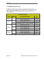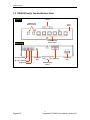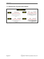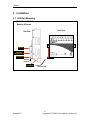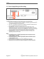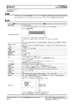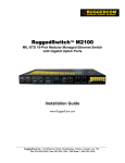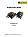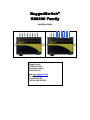
1
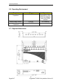
RuggedSwitch® RS8000 Family Installation Guide RS8000T RuggedCom Inc. 30 Whitmore Road, Woodbridge, Ontario Canada L4L 7Z4 Web: www.ruggedcom.com Tel: (905) 856-5288 Fax: (905) 856-1995 Toll Free: (888) 264-0006 Copyright COPYRIGHT © 2009 RuggedCom Inc. ALL RIGHTS RESERVED Dissemination or reproduction of this document, or evaluation and communication of its contents, is not authorized except where expressly permitted. Violations are liable for damages. All rights reserved, particularly for the purposes of patent application or trademark registration. This document contains proprietary information, which is protected by copyright. All rights are reserved. No part of this document may be photocopied, reproduced or translated to another language without the prior written consent of RuggedCom Inc. Disclaimer of liability We have checked the contents of this manual against the hardware and software described. However, deviations from the description cannot be completely ruled out. RuggedCom shall not be liable for any errors or omissions contained herein or for consequential damages in connection with the furnishing, performance, or use of this material. The information given in this document is reviewed regularly and any necessary corrections will be included in subsequent editions. We appreciate any suggested improvements. We reserve the right to make technical improvements without notice. Registered Trademarks RuggedRated™, ROS™ and eRSTP™ are trademarks of RuggedCom Inc. RuggedRouter® and RuggedSwitch® are registered trademarks of RuggedCom Inc. Other designations in this manual might be trademarks whose use by third parties for their own purposes would infringe the rights of the owner. Contacting RuggedCom Corporate Headquarters US Headquarters Europe Headquarters RuggedCom Inc. 30 Whitmore Road Woodbridge, Ontario Canada, L4L 7Z4 RuggedCom 1930 Harrison St., Suite 209 Hollywood, Florida USA, 33020 RuggedCom Unit 41, Aztec Centre, Aztec West, Almondsbury, Bristol United Kingdom BS32 4TD Tel: (905) 856-5288 Fax: (905) 856-1995 Toll-free: 1 (888) 264-0006 Tel: (954) 922-7938 x103 Tel: Fax: (954) 922-7984 Fax: Toll-free: 1 (888) 264-0006 Email: [email protected] +44 1454 203 404 +44 1454 203 403 Technical Support Toll Free (North America): 1 (866) 922-7975 International: +1 (905) 856-5288 Email: [email protected] Web: www.RuggedCom.com RuggedCom® 2 RuggedSwitch® RS8000 Family Installation Guide rev103 Federal Communications Commission Radio Frequency Interference Statement This equipment has been tested and found to comply with the limits for a Class A digital device pursuant to Part 15 of the FCC Rules. These limits are designed to provide reasonable protection against harmful interference when the equipment is operated in a commercial environment. This equipment generates, uses and can radiate radio frequency energy and, if not installed and used in accordance with the instruction manual, may cause harmful interference to radio communications. Operation of this equipment in a residential area is likely to cause harmful interference in which case the user will be required to correct the interference on his own expense. Warning: Changes or modifications not expressly approved by RuggedCom Inc. could void the user’s authority to operate the equipment. Important: The RS8000 family of Ethernet switches contains no user serviceable parts. Attempted service by unauthorized personnel shall render all warranties null and void. All RS8000 type units should be installed in a restricted access location where access can only be gained by service personnel or users who have been instructed about the reasons for the restrictions applied to the location and about any precautions that shall be taken; and access is through the use of a tool or lock and key, or other means of security, and is controlled by the authority responsible for the location. RuggedCom® 3 RuggedSwitch® RS8000 Family Installation Guide rev103 Table of Contents Table of Contents 1 Product Overview .................................................................................................................... 5 1.1 Functional Overview ....................................................................................................... 5 1.2 Feature Highlights........................................................................................................... 5 1.3 RS8000 Family Overview ............................................................................................... 6 1.4 RS8000 Family Front Panel Description......................................................................... 7 1.5 RS8000 Family Top and Bottom View ............................................................................ 8 1.6 RS8000 Family Top Views (Other Models)..................................................................... 9 2 Installation ..............................................................................................................................10 2.1 DIN Rail Mounting..........................................................................................................10 2.2 Power Supply Wiring and Grounding.............................................................................11 2.2.1 Power Supply - AC Input ..........................................................................................12 2.2.2 Power Supply – DC Inputs ........................................................................................12 2.3 HIPOT (Dielectric Strength) Testing ..............................................................................13 2.4 Failsafe Output Wiring and Specifications .....................................................................14 2.5 RS232 Port Wiring .........................................................................................................15 2.6 RJ45 Ports – Signal Description ....................................................................................16 3 Technical Specifications .........................................................................................................17 3.1 Power Supply Specifications..........................................................................................17 3.2 Failsafe Relay Specifications.........................................................................................17 3.3 Twisted Pair Data Port Specifications............................................................................17 3.4 Fiber Optical Specifications ...........................................................................................18 3.5 Type Test Specifications................................................................................................19 3.6 Operating Environment..................................................................................................20 3.7 Physical Dimensions......................................................................................................20 3.8 Agency Approvals..........................................................................................................21 4 Warranty.................................................................................................................................21 RuggedCom® 4 RuggedSwitch® RS8000 Family Installation Guide rev103 Product Overview 1 Product Overview 1.1 Functional Overview The RuggedSwitch RS8000 Family of switches (RS8000X) are substation hardened, fiber optical Ethernet switches specifically designed to operate in harsh environments such as those found in electric utility substations and harsh industrial environments. The RS8000 family provides multiple fiber optical port and speed selections as well as 10/100 RJ45 twisted-pair connectivity as well. Specifically tested to the same standards as mission critical protective relaying equipment (i.e. ANSI/IEEE C37.90 and IEC 60255), the RS8000X is ideally suited to form the Ethernet network in a UCA2 (Utility Communications Architecture 2.0) based substation automation network. Because the RS8000 series was designed to meet the demands of the substation environment it is also ideally suited for industrial automation networks based on Industrial Ethernet. The reliability of the RS8000X exceeds that of commercial Ethernet switches by having no rotating mechanical parts such as cooling fans and by utilizing high-temperature solid-state components. 1.2 Feature Highlights Utility Grade (i.e. substation hardened) per ANSI/IEEE C37.90, IEC 60255, and the new IEC 61850-3 (2002), IEC 61000-6-5 standards Operating temperature: -40 to 85C (no fan) Radiated RF Immunity: 35V/m per ANSI/IEEE C37.90.2 Power supply options: 12, 24 or 48 VDC, and universal HI (88-300VDC or 84-264VAC) Failsafe output relay for critical failure or error alarming Advanced layer 2 switching functions: 802.1p Message Prioritization, 802.1Q VLAN Full-duplex operation (no collisions) RuggedCom® 5 RuggedSwitch® RS8000 Family Installation Guide rev103 Product Overview 1.3 RS8000 Family Overview The RS8000 series Ethernet switch is available in several models to provide connectivity to a number of different design topologies and to serve a greater number of end-devices. The models details are shown below. All RS8000 models feature the same power supply options and mechanical dimensions. RS8000 Family Overview Model Quantity RS8000 8 RS8000T 2 6 4 RS8000A 2 2 RS8000H 4 4 RuggedCom® Ports Type Options and Media 100BaseFX Multi-mode Fiber 100BaseFX Single-mode Fiber 100BaseFX Multi-mode Fiber 100BaseFX Single-mode Fiber Auto-negotiating 10BaseT / 100BaseTx Twisted Pair 100BaseFX Multi-mode Fiber 100BaseFX Single-mode Fiber 10BaseFL Multi-mode Fiber 10BaseFL Single-mode Fiber Auto-negotiating 10BaseT / 100BaseTx Twisted Pair 100BaseFX Multi-mode Fiber 100BaseFX Single-mode Fiber Auto-negotiating 10BaseT / 100BaseTx Twisted Pair Connector Type MTRJ LC MTRJ LC RJ45 MTRJ LC ST ST RJ45 SC or ST SC or ST RJ45 6 RuggedSwitch® RS8000 Family Installation Guide rev103 Product Overview 1.4 RS8000 Family Front Panel Description Front Panel View 100BaseFX Ports MTRJ Connectors 10/100BaseTX Ports RJ45 Connectors Reset LED Indicators LINK/Activity Rx (Receive) Tx (Transmit) POWER LED T Failsafe Output Relay Power +/H = DC(+) / AC(Hot) -/N = DC(-) / AC(Neutral) Surge Ground Safety Ground Stud RS232 PORT Normally Open Common Normally Closed Fig. 1.4.1 RS8000 Family Front Panel Detail (Note: RS8000T Shown) ITEM LINK LED (Yellow) Tx LED (Red) Rx LED (Green) POWER LED (Red) RuggedCom® Activity Solid Blinking – Once per second Blinking Blinking Solid Comments Link Established Tx, Rx Activity Tx (Transmit) Activity Rx (Receive) Activity Power On 7 RuggedSwitch® RS8000 Family Installation Guide rev103 Product Overview 1.5 RS8000 Family Top and Bottom View DIN Rail Mounting Bracket Top View 100BaseFX Ports MTRJ Connectors 10/100BaseTX Ports RJ45 Connectors Bottom View +/H = DC(+) / AC(Hot) -/N = DC(-) / AC(Neutral) Surge Ground Reset Button Safety Ground Stud RS232 Port Failsafe Output Relay DIN Rail Mounting Bracket Fig. 1.5.1 RS8000 Family Top and Bottom View (Note: RS8000T Shown) RuggedCom® 8 RuggedSwitch® RS8000 Family Installation Guide rev103 Product Overview 1.6 RS8000 Family Top Views (Other Models) Figure 1.6 Top View of other RS8000 family models RuggedCom® 9 RuggedSwitch® RS8000 Family Installation Guide rev103 Installation 2 Installation 2.1 DIN Rail Mounting RS8000 Family DIN Rail Mounting & Release Front View Side View DIN RAIL DIN RAIL Mounting Latch Release Slot DIN RAIL Release Direction Screw Driver Release Action Fig. 2.1.1 RS8000 Family DIN Rail Mounting RuggedCom® 10 RuggedSwitch® RS8000 Family Installation Guide rev103 Installation 2.2 Power Supply Wiring and Grounding +/H = DC(+) / AC(Hot) -/N = DC(-) / AC(Neutral) Safety Ground Stud Surge Ground Fig. 2.2.1 RS8000 Family Power Supply Inputs The RS8000 family power supply inputs are identical and are connected as follows: 1. +/H = DC (+) / AC (Hot) is connected to the positive (+) terminal if the power source is DC or to the (Hot) terminal if the power source is AC. 2. -/N = DC (-) / AC (Neutral) is connected to the negative (-) terminal if the power source is DC or to the (Neutral) terminal if the power source is AC. 3. Surge Ground is connected to the Chassis Ground via a braided cable or other appropriate grounding wire. Surge Ground is used as the ground conductor for all surge and transient suppression circuitry internal to the RS8000 unit. NOTE: Surge Ground must be disconnected from Chassis Ground during HIPOT (dielectric strength) testing. 4. Chassis Ground is connected to the Safety Ground terminal for AC inputs or the equipment ground bus for DC inputs. Notes: 1. 88-300VDC Equipment: A 300VDC appropriately rated circuit breaker must be installed within 3m of the unit. 2. 100-240VAC Equipment: A 250VAC appropriately rated circuit breaker must be installed within 3m of unit 3. A circuit breaker is not required for 12, 24 or 48 VDC rated equipment 4. Equipment must be installed according to the applicable country wiring codes. RuggedCom® 11 RuggedSwitch® RS8000 Family Installation Guide rev103 Installation 2.2.1 Power Supply - AC Input Fig. 2.2.2 Power Supply – AC Input 2.2.2 Power Supply – DC Inputs Fig. 2.2.3 Power Supply – DC Inputs RuggedCom® 12 RuggedSwitch® RS8000 Family Installation Guide rev103 Installation 2.3 HIPOT (Dielectric Strength) Testing HIPOT (Dielectric Strength) Testing Disconnect Braided Cable during HIPOT (dielectric strength) testing! Braided Cable Fig. 2.3.1 HIPOT (Dielectric Strength) Testing NOTE: Units which are to be “HIPOT” tested in the field must have the braided ground cable(s) disconnected (see Fig. 2.3.1) during the HIPOT test. This is required in order to prevent the transient/surge suppression circuitry, which is connected to Surge Ground (see Fig. 2.2.1), from being activated during the HIPOT test. RuggedCom® 13 RuggedSwitch® RS8000 Family Installation Guide rev103 Installation 2.4 Failsafe Output Wiring and Specifications The “Failsafe” output relay is provided to signal critical error conditions that may occur on the RS8000 series switch. The contacts are energized upon power up of the unit and remain energized until a critical error occurs. One common application for this output, regardless of whether the switch is managed or unmanaged, is to signal an alarm if a power failure or removal of control power occurs. RS8000 Failsafe Relay Outputs Normally Closed Common Normally Open *** Normal contact state prior to power being applied to unit. *** Fig. 2.4.1 RS8000 Family Failsafe Output Relay RuggedCom® 14 RuggedSwitch® RS8000 Family Installation Guide rev103 Installation 2.5 RS232 Port Wiring The RS232 port is used for configuring the unit. A straight-through serial cable with a DB-9 connector is required. There is no need to crossover the Transmit and Receive signals from the PC side since this has been done internally as shown in the figure below. Fig 2.5.1 RS232 Female DCE pin-out Pin Signal 1 No Connection 2 Transmit Data 3 Receive Data 4 No Connection 5 Ground 6 No Connection 7 No Connection 8 No Connection 9 No Connection Table 2.5.1 RS232 Female DCE pin-out NOTE: This port is not intended to be a permanent connection and the cable shall be less than 2m (6.5 ft) in length. RuggedCom® 15 RuggedSwitch® RS8000 Family Installation Guide rev103 Installation 2.6 RJ45 Ports – Signal Description Units with 10/100Base-TX ports allow connection to standard Category 5 (CAT-5) unshielded twisted-pair (UTP) cable with RJ45 male connectors. The RJ45 receptacles are directly connected to the chassis ground on the unit and can accept CAT-5 shielded twisted-pair (STP) cables. If shielded cables are used, care must be taken to ensure the shielded cables do not form a ground loop via the shield wire and the RJ45 receptacles at either end. The figure below shows the shows the RJ45 port pin-out and LEDs. Figure 2.6.1 Pin 1 2 3 4 5 6 7 8 Case Table 2.6.1 Signal +Rx -Rx +Tx No Connection No Connection -Tx No Connection No Connection Shield (Chassis Ground) NOTE: RuggedCom does not recommend the use of CAT-5 cabling of any length for critical realtime substation automation applications. However, transient suppression circuitry is present on all copper ports to protect against damage from electrical transients and to ensure IEC 61850-3 and IEEE 1613 Class 1 conformance. This means that during the transient event communications errors or interruptions may occur but recovery is automatic. RuggedCom also does not recommended to use these ports to interface to field devices across distances which could produce high levels of ground potential rise, (i.e. greater than 2500V) during line to ground fault conditions. RuggedCom® 16 RuggedSwitch® RS8000 Family Installation Guide rev103 Technical Specifications 3 Technical Specifications 3.1 Power Supply Specifications Power Supply Type 12 – 24 VDC 24 VDC 48 VDC HI (125/250 VDC) 1 HI (110/230 VAC) 1 Minimum Input 10 VDC 18 VDC 36 VDC 88 VDC 85 VAC Maximum Input 36 VDC 36 VDC 59 VDC 300 VDC 265 VAC Fuse Rating 6.3A(F) 2 5A(F) 2 3.15A(T) 2 3.15A(T) 2 Maximum Power Consumption 15 W NOTES: 1. This is the same power supply for both AC and DC. 2. (F) Denotes fast-acting fuse, (T) denotes time-delay fuse 3. For continued protection against risk of fire, replace only with same type and rating of fuse. 3.2 Failsafe Relay Specifications Parameter Max Switching Voltage Rated Switching Current Value 30VAC, 80VDC 0.3A @ 30VAC 1A @ 30VDC, 0.3A @ 80VDC 3.3 Twisted Pair Data Port Specifications Data Port Media Distance Connector Type 10/100 Mbps Cat 5 UTP or STP 100m RJ45 RuggedCom® 17 RuggedSwitch® RS8000 Family Installation Guide rev103 Technical Specifications 3.4 Fiber Optical Specifications Mode / Connector Tx (nm) Cable Type2 (m) Tx Pwr (dBm peak) 3 (Min / Max) Rx Sensitivity (dBm Average) 3 Rx Saturation (dBm Peak) 3 Typical Distance (km) 1 Power Budget (dB) 10BaseFL MM / ST 820 50/125 -16.5/-10.6 -34.4 -11.2 2 21 10BaseFL SM / ST 1310 9/125 -23/-15 -38 -3 15 18 100BaseFX MM / ST 1310 50/125 -15.7 -33.5 -11 2 17 100BaseFX MM / SC 1310 50/125 -16/-11 -33 -11 2 17 100BaseFX MM / MTRJ 1310 50/125 -16/-11 -33.5 -11 2 17 100BaseFX SM / ST 1310 9/125 -27 / -14 -35 -3 5 8 100BaseFX SM / SC 1310 9/125 -13/5 -31 -4 20 20 100BaseFX SM / LC 1310 9/125 -15/-8 -31 -5 15 16.5 Speed Standard Notes: 1. Maximum segment length is greatly dependent on factors such as fiber quality, and number of patches and splices. Please consult RuggedCom sales associates when determining maximum segment distances. 2. To convert from average to peak add 3dBm. To convert from peak to average, subtract 3dBm. 3. Single-mode is available as an option. RuggedCom® 18 RuggedSwitch® RS8000 Family Installation Guide rev103 Technical Specifications 3.5 Type Test Specifications Electrical Safety Dielectric Withstand Levels 2 kV rms for 1 minute High Voltage Impulse Insulation Resistance 5 kV peak 500 VDC for 1 minute Electrical Environment High Frequency Disturbance (Oscillatory) IEC Surge Levels 2.5 kV @ 1MHz for 2s IEC Fast Transient 2 kV / 1 kV ANSI/IEEE Fast Transient IEC Radiated RFI Immunity ANSI/IEEE Radiated RFI Immunity ESD (Electrostatic Discharge) 4 kV 10 V/m 35 V/m 4 kV / 2 kV 15 kV (air discharge) 8 kV (contact) Atmospheric Environment Temperature (Dry Cold) Levels -40C Temperature (Dry Heat) 85C Humidity 95% non-condensing RuggedCom® Comments ANSI/IEEE C37.90 (1989) IEC 60255-5 (Section 6) IEC 60255-5 (Section 8) IEC 60255-5 (Section 6 Comments ANSI/IEEE C37.90.1 IEC 60255-22-1 IEC 61000-4-5 (Level 4) IEC 61000-4-4 (Level 4) ANSI/IEEE C37.90.1 IEC 61000-4-3 ANSI/IEEE C37.90.2 IEC 61000-4-2 (Level 4) Comments IEC 60068-2-1 Test Ad: 16 hrs @ -40C IEC 60068-2-2 Test Bd: 16 hrs @ 85C IEC 60068-2-30 Test Db: 6 cycles, 55C, 95% Humidity 19 RuggedSwitch® RS8000 Family Installation Guide rev103 Technical Specifications 3.6 Operating Environment Parameter Ambient Operating Temperature Range -40 to 85C Ambient Relative Humidity Ambient Storage Temperature 5% to 95% -40 to 85C Comments Ambient Temperature as measured from a 30cm radius surrounding the center of the RS8000 enclosure. Non-condensing 3.7 Physical Dimensions RuggedCom® 20 RuggedSwitch® RS8000 Family Installation Guide rev103 Warranty Parameter Dimensions Value 9.8 x 7.81 x 2.43 inches Comments (Length x Width x Height) (242,92) x (195,37) x (61,72) mm Weight Enclosure 5 lb (2.25 Kg) 18 gauge Galvanized Steel 3.8 Agency Approvals Agency CSA, CE FCC CISPR Standards CSA C22.2 No. 60950, UL 60950, EN 60950 EN 61000-6-2 FCC Part 15, Class A EN55022, Class A Comments Approved Approved Approved 4 Warranty RuggedCom warrants this product for a period of five (5) years from date of purchase. For warranty details, visit http://www.ruggedcom.com/ or contact your customer service representative. Should this product require warranty or service contact the factory at: RuggedCom Inc. 30 Whitmore Road, Woodbridge, Ontario Canada L4L 7Z4 Phone: (905) 856-5288 Fax: (905) 856-1995 RuggedCom® 21 RuggedSwitch® RS8000 Family Installation Guide rev103