1
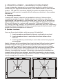
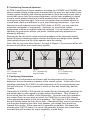
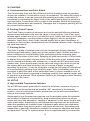
the
CustomSoundseries
Owner’s Manual
CW800E
CW600E
CWS10
CONTENTS
I.
Warranty Registration
II.
Unpacking
III. Materials and Tools
A. Required Tools
B. Other Tools
IV. Speaker Placement
A. Listening Locations
B. Speaker Locations
C. You in Relation to the Speakers
D. You in Relation to the Room Boundries
E. Positioning Surround Speakers
F. Positioning Subwoofers
V.
System & Supply
VI. Obstructions
VII. Installation
VIII. Connections
IX. Wiring
A. Rough-In Wiring
B. Conventional Wiring
C. Tricks of the Trade
X.
Grilles
A. Installing & Removing
B. Grille Alternatives
XI. Painting
A. Construction Dust and Paint Shield
B. Painting Finish Frames
C. Painting Grilles
XII. Set-up
A. High & Mid Frequency Switches
B. Listening—Balance, Range and Imaging
C. Recommended Power
XIII. Protecting Your Investment
XIV. In Case of Problems
XV.
Specifications
2
Congratulations on choosing PSB CustomSound Series speakers. Please take
the time to read the instructions in this guide, as they will help you enjoy the full
potential of your loudspeakers in any stereo or multichannel home theater
application.
I. WARRANTY REGISTRATION
We recommend you take a few moments now to register your warranty,
preferably on-line at psbspeakers.com/w/Warranty.html or via the enclosed
registration form so that we will be able to serve you better in the future.
II. UNPACKING
The packing materials of your PSB speakers are designed to protect them from
damage during shipping. Retain the packaging in case the need arises to
transport the speakers in the future.
III. MATERIALS AND TOOLS
The only other materials necessary to install CustomSound speakers are paint
and extra fine sandpaper if you wish to change the color of Grills and/or Finish
Frames from their standard white. Of course, wire cable of appropriate length and
size will be necessary to connect speakers to amplifiers (or volume controls) in
the music system.
A. Required Tools
The following tools are needed for normal, simple installations:
Tape Measure, Pencil, and Level
Utility Knife and Wallboard Saw (and extra blades)
Philips Screwdriver and Putty Knife
Drill and Bits (smaller for lead holes and larger for cabling)
Probe Wire (a heavy coat hanger can substitute for a short fish-tape)
Flashlight
B. Other Tools
Particularly when installing a quantity of speakers, or installing in wood
paneling or other wall materials, the following tools are desirable for neater
and more efficient installations:
Stud Finder (helpful—particularly with simple, wallboard-on-studs
construction)
Metal Straight Edge (Ruler or Framing Square) and Masking Tape
Wallboard Rasp/Sanding Block (or a piece of wire lath around a block)
Awl or Worn Screwdriver (for initial, exploratory holes) and Hammer
Wire Cutters/Strippers and Electrical Tape
Battery Screwdriver and Power Drill and Extensions (with extra bits)
Jig Saw and Blades
Wallboard Router and Cutout Bits
3
IV. SPEAKER PLACEMENT — MAXIMIZING YOUR ENJOYMENT
Proper loudspeaker placement is an essential ingredient to getting the best
sound from your high performance stereo, multi-channel audio or home theater
system. The goal is to reproduce faithfully the audio soundtrack the movie
director or music producer created without calling any attention to the speakers
themselves.
A. Listening Locations
Consider the desired, intended, and probable locations of listeners when
considering speaker locations. Ideally, listeners should have a clear line-ofsight/hearing to all speakers in their listening area—not too far off axis and not
obstructed by structure or furnishings—for most balanced frequency response.
Where will listeners be—primary and secondary? Where will listeners’ ears
be—sitting, standing, walking? No installation is absolutely ideal, but considering
listener locations with speaker location can greatly improve the final result—and
simplify the effort and expense to achieve it.
B. Speaker Locations
Here are three simple ideals, which are never fully satisfied:
1. Locate speakers equidistant to listeners, preferably at ear level.
2. Locate speakers closer to each other than their distance from
listeners.
3. Locate speakers symmetrically to each other and to their physical
surroundings.
Ideally, listeners will be equidistant from front right and left and center channel
speakers and from rear (or side) left and right surround channels for most
accurate spatial imaging. If listeners are too close to front or to rear channel
speakers the image cannot come together and flow seamlessly across. While
ear-level mounting is ideal, the swivel tweeters can be aimed towards the
listeners, increasing the accuracy of frequency response when speakers are
located further off axis from listeners’ ears. Most importantly, a center channel
speaker should be located centered on the TV screen—to keep center channel
sound coming from the center of the screen.
30°
30°
30°
4
30°
Balance adjustment can compensate for some physical location difference
between left and right. Time-delay adjustment of surround sound can
compensate for some physical location difference between front and rear. With
mono signals equidistant, symmetrical location is still desired to minimize
balancing requirements. Proximity to additional side wall, ceiling or floor surfaces
will cause increases and decreases in frequency response which are very difficult
to electronically equalize for smooth response overall—particularly when only
some of the speakers are affected.
All CustomSound models are designed to maintain the same tonal balance when
different models are mixed in a system. The same model should be used in
symmetrical listening locations in a system—front left and front right; rear left and
rear right.
Each CustomSound speaker carton contains a full-size template of the front of
the speaker. These templates can be used when initially locating speakers and
then when marking and cutting out speaker locations. We encourage temporarily
taping templates in the intended locations and then sitting in the primary listening
location and considering the above guidelines again—also realizing that behindthe-wall conflicts will probably require some adjustment to the intended locations
before they are final.
C. You in Relation to the Speakers
Where you sit in relation to your speakers obviously makes a difference too. The
proportions of the particular triangle formed by your front left and front right
speakers and you matter. (You may need to send more power to the more
distant speaker to compensate if you get much further from one speaker than the
other.) The overall distances involved also matter. As you get further from the
speakers, more sound reflected from your room’s surfaces (in contrast to the
sound coming directly from the speakers) reaches your ears, and the original
spatial relationships in a recording are changed as your room “takes over.”
Sometimes the result is a mellower, more “integrated” sound. Other times, it’s a
more strident or annoyingly “echoey”—or other—quality. Once again, the
particular dimensions and surface materials of your room play a part. And
depending on what seems more realistic and/or enjoyable to your ears, you may
choose to sit at a great distance or have close-up, “near-field” sound.
D. You in Relation to Room Boundaries
Changing your own position with respect to a room’s boundaries may also bring
a big effect, sometimes for a small change. Getting further from the wall behind
you may make sound more precise and localized. Getting closer may make
sound more “mellow” and integrated. Coming too close—to back wall, side wall,
or (especially) a corner— you may experience a major peak or cancellation of a
certain band of frequencies. It depends on factors we can’t cover fully here but
do get into on our web site.
As you consider the three relationships we have outlined, the idea is to
manipulate whatever variable is easiest and most productive for improving your
listening experience. Be sure to base your judgements on listening to a good
variety of recordings of vocals, and acoustic instruments, soloists, different
movies and musical instruments to most easily recognize tonal balance shifts.
5
E. Positioning Surround Speakers
All PSB CustomSound Series speakers including the CW800E and CW600E are
timbre matched (have similar tonal characteristics) for easy mix and match home
theater system flexibility and ultimate performance. Most surround sound (that is
sound that comes from the surround speakers, not the front speakers) is meant
more to create greater depth and overall ambience than to localize effects as
coming from a particular spot. How much you prefer these localized effects vs.
overall sonic depth and diffusion is up to your listening preferences. If you are
listening to multi-channel music from DVD-Audio or SACD, you may want the
maximum localization of instruments. However, for most home theater
applications a diffuse soundfield might be preferred. You can locate your surround
speakers to produce the effects you prefer, whether precisely pinpointed or
pleasantly diffused.
Most people find it best to mount surround speakers on the side walls slightly
behind the prime listening position and two feet above ear height when seated
(this typically places the top of the speaker near the ceiling.)
Note, that as you move from Figure 1 through to Figure 3, the surround effect will
become more diffuse and more evenly spread.
30°
30°
30°
30°
30°
30°
All distances
are equal
Figure 1
6.1/7.1 System using
two Surrounds
Figure 2
6.1/7.1 System using
three Surrounds
Figure 3
6.1/7.1 System using
four Surrounds
F. Positioning Subwoofers
The location of subwoofers will interact with the dimensions of the room to
determine the low frequency response of the overall system. Unlike with a free
standing subwoofer the CWS10 in-wall subwoofer can't be mounted away from
the wall surfaces! The key question is where on the wall should they best be
located.
Generally the CW600 or 800 should be located first by following the guidelines for
placement (above) with regard to angles around the listener. Their location is
more critical than the location of the subwoofers. Once the main front speakers
are located then you may want to mount the CWS10(s) in a spot that visually
looks appropriate relative to the front speakers. This might be in the same stud
bay but directly below the front left or right. Alternatively they may be mounted at
just the same height as the other front speaker, yet outside them and more
towards the corners. Either approach is generally acceptable. Be aware that
mounting the CWS10 closer to a corner will generally increase the overall bass
level and that will increase its output capability, a good thing.
6
Avoid mounting the subwoofers at the rear of the room or on the side walls far
from the front wall. Although our sense of location for very low frequencies is
poor it will still degrade the blend between bass and upper frequencies when the
subwoofer and the front speakers are mounted far apart. An exception to this is
when one subwoofer is mounted in the center of the front wall and a second
subwoofer is mounted in the center of the rear wall. Recent studies have shown
such a technique to generally give a very good low frequency room response.
V. SYSTEM AND SUPPLY
Overall, a musical source—audio or video—is fed first through a preamplifier with
switching and tone controls—and then through a power amplifier and onwards to
each speaker. The preamplifier provides a variety of controls—bass, treble, and
balance left to right. Surround processors, operating between the preamplifier
and amplifier stages, can provide surround decoding and another level of
channel balancing—front left, right, and center; surround left and right; and
subwoofer. An equalizer before the amplifier can provide some adjustment to
smooth response for field conditions and preferences. Multiple amplifiers may be
used for multiple zones and speaker loads.
VI. OBSTRUCTIONS
With tentative speaker locations determined, potential obstructions must be
explored and the conflicts resolved: Structural; Mechanical—Electrical, Plumbing,
and HVAC; and Furnishings. Note: The CW800E and CW600E have a large
enclosure and must have a full (16” center) unobstructed stud bay with no other
wiring or plumbing.
Temporarily mark and view tentative speaker locations and the existing
construction carefully to determine the existing structure and mechanical
installations and potential obstructions. Adjust the speaker layout, the furnishings,
the mechanical, and/or the structural to resolve the conflicts. Layout, review, and
resolution on building plans can be a very efficient process. However, some
conflicts will inevitably appear and need to be resolved as actual conditions are
reviewed and as installation proceeds.
Most typically, residential walls are constructed of wooden studs—nominally 2" x
4", but measuring 1½” x 3½" (sometimes, particularly on exterior walls 2" x 6",
measuring 1½" x 5½") and normally located on 16" centers—with 14½" between
studs. This stud pattern usually begins from one, exterior corner and results in a
smaller than normal spacing at the other corner. The full height "common" studs
extend from a flat "sole" plate on the floor to a "top" plate (often doubled) at the
top of the wall. Top headers of doubled 2" x 4"s (or larger) are placed on edge
spanning over doorways and windows, and doubled sill headers run under
window openings. "Trimmer/jack" partial studs run under the ends of all headers,
doubled against full studs against the ends of all headers. Shorter partial "cripple"
studs run over headers to the top plate and under sills to the bottom plate—at
nominal spacing. Blocking may be between studs about mid-wall, behind
cabinets and other fixtures mounted to the wall, and over and under ductwork
through the stud cavity. Electrical receptacles and switches are mounted in
electrical boxes, usually mounted to a stud. Removing electrical cover plates in
finished walls is a good initial step to determine where studs are located.
Floors typically are constructed of wooden joists—nominally 2" x 8" or deeper,
but measuring 1½" x 7¼" or deeper and normally located on 16" centers (but not
7
uncommonly on 12" centers). Roofs typically are constructed of wooden
rafters—nominally 2" x 6" or deeper, but measuring 1½" x 5½” and located on 16"
centers (but not uncommonly on 24" centers). Ceilings are usually backed by 1" x
3" strapping leveled beneath the floor joists or roof rafters and located on 16"
centers.
Electrical cables run to, and most often from, all electrical boxes—which are
grouped on circuits. Plumbing supply, drain and vent lines run to and from all
plumbing fixtures—which are grouped on vertical risers. Heating supply lines
circulate through radiation fixtures—which are grouped in zones off vertical risers.
HVAC ductwork runs to all supply grills and from all return grills. Control wiring
(sometimes tubing) runs to all controls.
Corner bay locations should be avoided since at least one corner bay is usually
smaller than normal, hence the speaker will not fit, and closeness to the side wall
will cause some unevenness in frequency response. Electrical power wiring
should not run close to the speaker or it's audio supply; crossing away from the
speaker and its supply has minimal effect.
Tricks of the Trades—Nothing's Plumb, Square, or True
All people in construction realize that it is an exacting but inexact craft—nothing
is exactly, absolutely plumb, square, or true. The craft is to understand and
respect the tolerances of materials, tools, makers, and users—what will look right
to the eye, is reasonably possible to build, and will retain it's position over
years—within the budgets of money and time. Planning, measuring, and
coordinating are important; but conflicts, tradeoffs, and imperfections are
inevitable in the final construction. Pre-construction drawings are very valuable to
further the process mentally before the physical begins. Post-construction, asbuilt drawings are valuable to assure performance and aid modification.
However; no drawings will be entirely complete or consistent with the
construction. Proceed with an open and responsive mind. Prepare to be
surprised, challenged, and rewarded—to solve the many small riddles along the
path to completion.
VII. INSTALLATION
These speakers use a particularly effective mounting technique with toggle style
mounting clamps. They are so named because the mounting clamp toggles out
from a rest position prior to tightening down. As shipped, this mounting clamp
parks on a flat on its mounting tower, thus staying out of the way for easy
insertion of the system into the wall cutout. When a screwdriver is applied to the
mounting screws it first turns the clamp 90 degrees, removing it from its resting
place, and then brings the clamp down a track in the tower. With further
tightening it finally clamps the wall firmly. This clamping style gives firm clamping
for freedom from rattles, and great convenience of installation. The CW800E has
16 of these clamping assemblies. The CW600E has 12.
A template is provided for marking the speaker cutout. It has a series of slots for
tracing the cutout and also an outline of the system to confirm that the flange
won't interfere with any wall features.
At each intended speaker location measure and mark with a pencil the intended
center of the speaker. Near the intended center make a small initial exploratory
hole with an awl or (worn) screwdriver and hammer, a wallboard cutout saw, or a
8
drill. If the awl, screwdriver or saw hits "solid" after the wallboard or plaster is
pierced or if the drill produces sawdust after the initial wallboard/plaster dust, you
have probably hit a wooden stud—which will obstruct that location. If drilling
becomes harder after piercing the wallboard or plaster, remember it could be
plumbing, mechanical, or electrical material. If you feel unusual resistance or
sense an obstruction, stop. Consider the situation and carefully make another
small exploratory hole about 1 1/2" to the side where you would prefer the
speaker location to move.
When your small exploratory hole avoids obvious obstruction, enlarge that hole
slightly with the screwdriver and hammer (or wallboard saw) until you can extend
a short probe wire/fish-tape through the hole and determine the location of the
stud on each side and other obstructions. Adjust your layout if necessary and
then enlarge the hole slightly so that you can see into the wall cavity (aided by a
flashlight) and confirm there are no further obstructions.
Continue this process of initial layout, exploratory holes, determining hole, and
confirming hole at each intended location in a related group before proceeding
with full cutouts. You can then modify the initial layout as required to avoid the
inevitable discovered conflicts and maintain a desired layout for acoustical
performance and visual aesthetics—while avoiding and minimizing any excess
cutting and patching.
Cut a hole large enough to see left and right stud locations. Center the template
on the wall based on those locations. The cutout will have to be well centered
between the wall studs. There isn’t enough space between the studs to allow any
side shift.
Now cut out the full rough-opening being careful to avoid over-cutting, breaking
edges of the opening, or damaging surrounding paint or wallpaper finishes. A
wallboard handsaw, preferably with replaceable blades, is the normal tool.
Powered drywall cutters can also be used if you are careful to cut in a straight
line or if you use a guide. The Finish Frames are about 3/4" wide around the
Grilles on the finish surface and extend about 5/8” beyond the rough opening
cutout, which should be quite adequate cover with reasonable care in layout and
cutout.
Check that openings are large enough and plumb by test fitting the speaker into
the opening. A wallboard rasp block/plane is very useful to slightly expand and
square up openings. A small level on or against the Frame easily confirms level
and plumb.
Place the system into the wall cutout. If there is extra slack in the cutout then
level and position the system before tightening the screws or after slightly
tightening one or two of the screws. Use a number 2 Philips head screwdriver or
any style and size that properly fits the screw head. Note: using bits that are too
small will lead to damaging the screw head and may make it very difficult to
sufficiently tighten or untighten the mounting screws.
Initial tightening may take considerable force as the screw forms a thread
through the mounting leg. This will loosen as the screw continues to turn. Set
driver torque with just enough force to start the screw turning. DO NOT
OVERTIGHTEN. The system has been well designed to prevent stripping or
damage from over tightening but PSB cannot be responsible for damage due to
unreasonable force being used when mounting the system.
9
Should it ever be necessary to remove the system from the wall, then unscrew
each leg (counter clockwise) in turn. As you unscrew the screw head will lie flat
in the frame until near the end of its travel, where the screw starts to rise. STOP
AT THAT POINT. Further turning will remove the screw from the assembly and
will make it more difficult to remove the system. The dog leg clamps are held at
the top of the mounting tower and should not fall off or down into the wall cavity,
UNLESS excessive force and continued counter-clockwise turning are used.
When each mounting screw is back out as described above you should be able
to remove the system. Because the clamps are not parked in the starting
position as when the system was first mounted, some of them may interfere with
the system's removal. Usually some wiggling can jostle each clamp into a
position where it isn't interfering. Using a manual screwdriver to apply slight
counterclockwise pressure should also turn a clamp out of the way. (Start with
the screws on one end of the system and turn each slightly. Angle the system
out a little more as each clamp moves out of the way.)
VIII. CONNECTIONS
Important: Always turn off your electronic equipment before connecting speakers.
Selecting Speaker Wire
We recommend the following
gauge of standard twoconductor wire for the wiring
distances specified; if you
prefer, you can use heavier
(lower-gauge) wire.
Under 25 ft (7.5 m):
25-50 ft (15 m):
Over 50 ft (30 m):
16-gauge – (1.3 mm)
14-gauge – (1.6 mm)
12-gauge – (2.0 mm)
You may wish to audition and compare the performance of some of the specialty
audio interconnects and speaker cable available from your dealer.
IX. WIRING
A. Rough-in Wiring
Typically, a cable with a wire pair connects each speaker to the signal sources,
either directly or through a local volume control. The speakers must be wired
appropriately for the intended control. The impedance loads of speakers must be
balanced with the capabilities of the amplifier(s). In some, mono only systems a
single wire may "daisy chain', entering from one speaker to another—beginning
and ending at the amplifier. If biamplification or biwiring is desired for increased
dynamic response and power handling, a second cable pair of wires must be run
to the speaker. Wire size should increase with longer runs—usually 16 AWG
stranded copper wire is minimal, with 12AWG desirable for longer runs. Audio
cable should avoid the electrical power wiring to avoid interference, which can be
audible—never running directly adjacent to it and crossing at right angles, when
necessary. Holes are normally located in the middle one-third of the framing
depth to minimize structural effects. If wire is within 1" of the front face of the
framing, it should be covered with (standard) steel protection plates to prevent
later fasteners from piercing the cable.
Wiring should be run to each back frame and inserted through one of the integral
wire clamps (no other fastener is required). Leave some additional wire at every
end, in case of a later shift; and dress the wire into the wall cavity, away from the
opening.
10
B. Conventional Wiring
Connect speakers identically to your amplifier or receiver on each channel Red
amp/receiver terminal to Red speaker terminal, Black to Black. This will ensure
that the diaphragms of the speakers on both channels move forward and
backward together (“in-phase”), rather than in opposition (“out-of-phase”). Inphase connection provides maximum clarity and bass, while out-of-phase
connection results in frequency cancellations and produces thinner and less
distinct sound—with less bass, vague vocal quality, and no solid center image.
To help ensure the proper connection, the two separate conducting wires in a
standard two-conductor speaker cable are coded in one way or another to be
distinguishable from each other. (The jacket of one wire may be ribbed or
marked with “+” signs, or one wire under the insulation may be a different color
from the other.) Use this wire-coding, together with the amp/receiver and
speaker color-coding, to be sure you are connecting the same wire of a given
pair to a like-coded terminal at both ends of your connection. Assure all wiring
terminals are tightened firmly but be careful not to overtighten and damage the
connectors.
The symmetrical array assures symmetrical performance above and below the
tweeter midpoint, the center of the speaker.
C. Tricks of the Trades—Drilling
When running wire through wooden framing, drill clean holes slightly larger and
aligned with each other to be able to pull cable through in longer sections with
minimal snagging. Auger style drill bits with threaded tips are self-feeding, can
chew through an occasional nail, and save much strain (although they can
become jammed in thick timbers). Right angle drills help in narrow spots to get
holes drilled and to maintain hole alignment. Short spade bits also get the job
done more easily in tight spots between studs.
X. GRILLES
A. Installing and Removing
Install Grilles by aligning one edge and corner against the Finish Frame and then
working the edges and corners of the Grille into the Finish Frame—avoiding force
which can bend the grill or scratch the edges of the Finish Frame.
Removing a Grille is most easily accomplished without scratching the finish by
inserting an unfolded paper clip or a small brad nail into a perforation and gently
pulling forward at several locations near a corner to start the removal. Once a
corner is free, work your way along the grille until your second corner is free.
Only then can you pull on the grille evenly with two hands. Rocking in and out will
release the whole grille and prevent serious bending.
B. Grille Alternatives—Scrims, Hole Shapes and Sizes
Grilles must be designed for acoustical transparency and also for visual
opaqueness, and paintability. The relatively small perforations in a slightly thicker
material provide visual opaqueness, paintability and strength, while maintaining
acoustical transparency.
11
XI. PAINTING
A. Construction Dust and Paint Shield
The Construction Dust and Paint Shield should be installed when the speaker
drivers are installed, if construction is not yet completed. The shield fits snugly to
protect the drivers. It can be removed after painting and other construction is
completed by squeezing the finger holds in the shield and pulling the shield out
from the frame. Construction dust or paint on the speaker drivers will negatively
affect their performance and warranty. Damages due to improper painting will not
be covered under warranty.
B. Painting Finish Frames
The Finish Frame is made of aluminum and can be painted following standard
practices and techniques. Be sure the frame is clean and dry, free of any mold
release agent residue and of any construction dust. Lightly and evenly scuff with
extra fine sandpaper, rounding square edges slightly, to ensure good paint
adhesion. Apply two to three coats, thinned slightly with a paint conditioner, to
produce an even surface. Imperfections can be sanded between coats. Spraying
will yield best results.
C. Painting Grilles
The Grille is made of painted metal and can be painted following standard
practices and techniques. Apply two or three coats of paint, thinned well with a
paint conditioner to avoid blocking Grille perforations while increasing paint
coverage of the sides of the holes. Spraying will yield best results. A roller tends
to deposit too much paint, blocking holes. While the paint is wet, blocked holes
can be cleared individually with a paper clip, or small nail (#18 wire brad is the
closest size). Some excess paint can be removed using a dry brush to pick-up
the excess paint and then brushing it out on a scrap of paper or rag and
repeating the process. It may be preferable to wipe the wet paint off with thinner
or a rag and begin painting more carefully again. With a contrasting color it is
important to paint the sides of the perforation holes to show consistent color off
axis. This is best done by spraying or brushing carefully from several angles side
to side and up and down. Allow a painted Grille to dry thoroughly before carefully
installing it in the frame.
XII. SETUP
A. High and Mid Frequencies Switches
We at PSB have spent great effort to make the frequency response of your inwall system as flat and neutral as possible. Still, variations in the listening
position, room acoustics and listener preferences can be well accommodated
using a few chosen controls.
Adjustment to high frequencies response may be desirable when the speakers
are installed in locations surrounded by hard surfaces that reflect the sound
output with very little absorption, causing a "hardness" to the sound (and/or with
some electronics). Adjustment to mid frequencies response may be preferred
when the speakers are installed close to adjacent walls which can emphasize
some upper bass frequencies (and/ or with some electronics). Decreasing mid
frequencies is generally desirable to smooth the crossover transition and avoid
an upper bass "hump" in systems where bass is supplemented by a subwoofer.
12
Decreasing high and mid frequencies increases relative bass response, while
decreasing efficiency and sound power output.
To modify the response, simply flip the baffle-mounted switch or switches to the
alternate position—pressing the upper half gives the normal position - pressing
the bottom half gives the decreased position as shown in the graphic of the
adjacent label. These heavy-duty switches are designed to handle the currents of
high level sound without compromise.
B. Listening—Balance, Range, and Imaging
Our goal is to provide listeners with completely convincing, "being there"
performance. In-wall installations place greater physical limits on systems than
freestanding box systems. However, their performance, particularly considering
the physical limits and the resulting minimal intrusion into the listening space, can
be startling.
Final judgments on the quality of the sound output are of course personal. We
encourage listening to the speakers with clear and familiar recordings—
particularly of female and male voices and acoustic instruments—to convince
and satisfy listeners of the natural tonal balance, wide frequency and dynamic
range, and spatial imaging delivered.
C. Recommended Power
We recommend amplifiers and receivers rated from a range of 15-300 watts. For
playing at consistently room-filling volume, a minimum of 100 watts is usually a
good idea. Be wary of driving low-powered amplifiers to their limits as underpowering can cause permanent speaker damage.
XIII. PROTECTING YOUR INVESTMENT
A.
For full, year-after-year enjoyment from your speakers, you should
respect their limits. Excessive volume levels can damage even the most
“bullet-proof” speakers, especially over extended time periods.
B.
When listening to music or movies at very loud volume, you shouldn’t
turn up bass or treble all the way or close thereto. This sends
tremendously increased, disproportionate power into the speakers, and
may well damage them. Some loudness compensation (“Loudness”)
controls, which boost both bass and treble, can also be troublesome at
high volume. They are intended only for low-volume listening.
C.
Finally, you should be aware that when amplifiers and receivers are
pushed to their limits to produce excessive volume levels, they are driven
into “clipping” and can do severe damage—especially to tweeters. Often,
the damage is done by underpowered amplifiers, which may reach their
limits very soon. When such units begin to “clip” the audio waveform,
they may generate high-frequency “spikes” of tremendous power. More
tweeters have probably been destroyed by this phenomenon than any
other. If using your speakers at loud levels, listen carefully for any sign
of harsh, garbled midrange and diminishing intelligibility—and turn the
volume down right away if you detect it.
NEVER TURN UP THE VOLUME ALL THE WAY TO SEE HOW LOUD
YOUR SYSTEM WILL PLAY!
13
XIV. IN CASE OF PROBLEMS
A.
Lower volume if a speaker begins to sound distorted or seems to be
missing certain frequencies, to check first to see whether playing at
somewhat lower volume seems to clear up the problem. It can be
especially important to turn down the volume right away if you have
pushed a low-powered amplifier or receiver past its comfortable limits as
discussed in the “Protecting Your Investment” section.
B.
Isolate the problem to the electronics or the speakers and, if the
speakers, to specific speakers. Interchange the speaker wire
connections on your amplifier or receiver between channels, so that the
left speaker is connected to the right channel, or vice versa. If the
problem shifts to the other speaker, the problem is not in the speaker but
in the electronics.
C.
Another component—or, very often, a cable or connection problem
between components—may be at fault. If the problem stays in the same
speaker, irrespective of the channel to which it’s connected—and after
changing the connecting wire—the speaker itself probably needs service.
D.
See your dealer if you require service. PSB dealers are equipped to
handle almost all problems. If you have moved since your purchase, the
nearest authorized PSB dealer should be able to help you. You may
locate your nearest PSB authorized dealer on-line at
www.psbspeakers.com/r/list.html. If the problem is not resolved, please
contact us, providing the Model name, Serial Number, date of purchase,
dealer name, and a full description of the problem.
We appreciate your purchase, and hope this owner’s guide helps you enjoy the
exceptional satisfaction that PSB speaker systems have to offer. We wish you
many years of enjoyable listening!
Notes on environmental protection
At the end of its useful life, this product must not be disposed of with regular
household waste but must be returned to a collection point for the recycling
of electrical and electronic equipment. The symbol on the product, user's
manual and packaging, point this out.
The materials can be reused in accordance with their markings. Through
re-use, recycling of raw materials, or other forms of recycling of old products,
you are making an important contribution to the protection of our
environment.
Your local administrative office can advise you of the responsible waste
disposal point.Nous vous félicitons d'avoir choisi les enceintes PSB série
CustomSound. Veuillez prendre le temps de lire les instructions contenues
dans ce guide car elles vous aideront à profiter au maximum de vos
enceintes dans toute application stéréo ou de cinéma-maison à canaux
multiples.
14
XV. Specifications
CW800E
CW600E
CWS10
38-33,000Hz
45-33,000Hz
87dB
89dB
86dB
88dB
30-200Hz
(with CWA-1)
90dB
92dB
4 Ohms
6 Ohms
4 Ohms
15-300 Watts
15-200 Watts
50-300 Watts
1” (25mm) Aluminum Dome
with Ferrofluid
1” (25mm) Aluminum Dome
with Ferrofluid
Midrange (Nominal)
2 x 4 1/2” (115mm)
Woven Fiberglass Cone,
Cast Basket,
Rubber Surround
3/4” (19mm) Voice Coil
12oz (340g) Magnet
2 x 3 ½” (90mm)
Woven Fiberglass Cone,
Cast Basket,
Rubber Surround
3/4” (19mm) Voice Coil
10oz (280g) Magnet
Woofer (Nominal)
2 x 8” (203mm)
Woven Fiberglass Cone,
Cast Basket,
Rubber Surround
1 ½”(38mm) Voice Coil
40oz (1100g) Magnet
2 x 6 1/2” (165mm)
Woven Fiberglass Cone,
Cast Basket,
Rubber Surround
1 1/4”(32mm) Voice Coil
30oz (850g) Magnet
Crossover
2,200Hz, B3
300, L4
2,200Hz, B3
300, L4
EQ Adjustment
HF and MF Level BaffleMounted High-Current
Switches
HF and MF Level BaffleMounted High-Current
Switches
Connectors
Gold-Plated, 12 AWG
Binding Posts
Gold-Plated, 12 AWG
Binding Posts
Gold-Plated, 12 AWG
Binding Posts
Aluminum, White, Paintable
Black Textured Finish
Aluminum, White, Paintable
Black Textured Finish
Aluminum, White, Paintable
Black Textured Finish
Aluminum, White, Paintable
Round, Packed Mini-perf
Aluminum, White, Paintable
Round, Packed Mini-perf
Aluminum, White, Paintable
Round, Packed Mini-perf
14” x 38½” x 3 3/4”
(356mm x 978mm x 95mm)
13” x 37 1/2”
(330mm x 952mm)
14” x 31 3/4” x 3 3/4”
(356mm x 806mm x 95mm)
13” x 30 13/16”
(330mm x 783mm)
14” x 38 1/2” x 3 3/4”
(356mm x 978mm x 95mm)
13” x 37 ½”
(330mm x 952mm)
11/16” (18mm)
11/16” (18mm)
11/16” (18mm)
Frequency Range
Response
On Axis @ 0° ±3dB
Sensitivity
Anechoic Chamber
Typical Listening Room
Impedance
Nominal
Input Power
Recommended
Acoustic Design
Tweeter (Nominal)
Finish/Construction
Finish Frame
Baffle
Grille
Material
Perforation
Dimensions (W x H x D)
Finish Frame
Rough-in/Mounting Hole
Cover/Overlap
15
2 x 10” (254mm)
Woven Fibreglass Cone
Rubber Surround
2” (50mm) Voice Coil
Front Mount Neo Magnet
PSB Speakers
633 Granite Court
Pickering, Ontario L1W 3K1
CANADA
www.psbspeakers.com
888-772-0000 (North America)
905-831-6555 (International)
Fax: 905-837-6357
OM-CW-E, Rev B, 1106