1
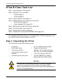
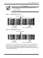
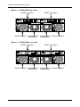
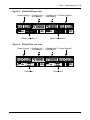
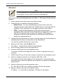
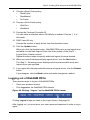
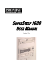
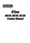
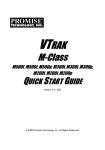
VTRAK
E-Class
E610f, E610s, E310f, and E310s
QUICK START GUIDE
Version 2.0
© 2007 Promise Technology, Inc. All Rights Reserved.
VTrak E-Class Quick Start Guide
VTrak E-Class Task List
Step 1: Unpacking the VTrak (below)
Step 2: Mounting VTrak in a Rack
•
E610f/s (page 6)
•
E310f/s (page 8)
Step 3: Installing Disk Drives (page 11)
Step 4: Making Management and Data Connections
•
Fibre Channel (page 15)
•
Serial Attached SCSI (page 20)
Step 5: Making Serial Cable Connections (page 26)
Step 6: Connecting the Power (page 27)
Step 7: Setting the IP Address (page 29)
Step 8: Creating Disk Arrays with WebPAM PROe (page 35)
For complete information about your VTrak E610f/s or E310f/s subsystem, see
the VTrak E-Class Product Manual on the CD.
Step 1: Unpacking the VTrak
The VTrak box contains the following items:
•
VTrak Unit
•
RJ11-to-DB9 serial data cable
•
Quick Start Guide
•
•
Front bezel and key
•
Left and right center-mount
brackets
Screws for disk drives
(E610f/s: 70, including 6 spares)
(E310f/s: 50, including 2 spares)
•
1.5m (4.9 ft) Power cords (2)
Left and right mounting rails
•
CD with SNMP files, Product
Manual and Quick Start Guide
•
Warning
The electronic components within the VTrak disk array are
sensitive to damage from Electro-Static Discharge (ESD).
Observe appropriate precautions at all times when handling the
VTrak or its subassemblies.
2
Step 1: Unpacking the VTrak
Important
Use the following categories of network cables with VTrak:
•
Cat 6, preferred
•
Cat 5E, minimum
Figure 1. VTrak E610f/s front view
Drive Carrier LEDs
Drive Carriers
Power and Status LEDs
Figure 2. VTrak E310f/s front view
Drive Carrier LEDs
Drive Carriers
Power and Status LEDs
A defective drive may be replaced without interruption of data availability to the
host computer. If so configured, a hot spare drive will automatically replace a
failed drive, securing the fault-tolerant integrity of the logical drive. The selfcontained hardware-based RAID logical drive provides maximum performance in
a compact external chassis.
3
VTrak E-Class Quick Start Guide
Figure 3. VTrak E610f rear view
RAID Controller 1
RAID Controller 2
Mgmt
FC 1
4
2
FC 2
Mgmt
UPS
FC 1
4
2
1
1
Gb/s
Gb/s
4
2
115200
8N1
FC 2
UPS
4
2
1
1
Gb/s
Gb/s
115200
8N1
Power Supply 1 Cooling Unit 1 Cooling Unit 2 Power Supply 2
with Battery
with Battery
Figure 4. VTrak E610s rear view
RAID Controller 1
RAID Controller 2
Mgmt
Mgmt
UPS
115200
8N1
UPS
115200
8N1
Power Supply 1 Cooling Unit 1 Cooling Unit 2 Power Supply 2
with Battery
with Battery
4
Step 1: Unpacking the VTrak
Figure 5. VTrak E310f rear view
Power Supply 1 Cooling Unit 1 Cooling Unit 2 Power Supply 2
with Battery
with Battery
I
I
O
O
Mgmt
FC 1
FC 2
4
Mgmt
UPS
FC 1
4
2
2
1
1
Gb/s
Gb/s
4
2
115200
8N1
FC 2
UPS
4
2
1
1
Gb/s
Gb/s
115200
8N1
RAID Controller 2
RAID Controller 1
Figure 6. VTrak E310s rear view
Power Supply 1 Cooling Unit 1 Cooling Unit 2 Power Supply 2
with Battery
with Battery
I
I
O
O
Mgmt
Mgmt
UPS
115200
8N1
UPS
115200
8N1
Controller 2
Controller 1
5
VTrak E-Class Quick Start Guide
Step 2: Mounting VTrak in a Rack
E610f/s
The E610f/s subsystem installs to the rack using the supplied mounting rails. You
can also use your existing rails.
Figure 1. VTrak E610f/s mounted in a rack with the supplied rails
Vertical Rack Post
VTrak E610f/s
Mounting rails (included)
mount outside the rack post
Handles mount
outside the rack post
Cautions
•
At least two persons are required to safely lift, place, and
attach the VTrak subsystem into a rack system.
•
Do not lift or move the VTrak subsystem by the handles,
power supplies or the controller units. Hold the subsystem
itself.
•
Do not install the VTrak subsystem into a rack without rails to
support the subsystem.
•
Only a qualified electrician who is familiar with the installation
procedure should mount and install the VTrak subsystem.
•
Be sure all switches are OFF before installing the VTrak
subsystem or exchanging components.
To install the E610f/s subsystem into a rack with the supplied mounting rails:
1.
Check the fit of the mounting rails in your rack system. See Figure 2.
2.
Adjust the length of the mounting rails as needed.
6
Step 2: Mounting VTrak in a Rack
3.
Attach the mounting rail assemblies to the outside of the rack posts, using
the attaching screws from your rack system.
Be sure the support is on the bottom facing inward.
4.
Square the rail assemblies in the rack.
5.
Tighten the adjustment screws and the attaching screws.
6.
Place the VTrak subsystem onto the rails.
7.
Secure the VTrak subsystem to the rack through each handle, using the
attaching screws from your rack system.
Figure 2. Rack mount assembly diagram
Rack front post
Rack back post
Rail attaching screw
(not included)
Rail attaching screw
(not included)
Front rail
Rear rail
Flange
Support
Rail adjustment screw
Rail adjustment screw
Inside of post
Inside of post
7
VTrak E-Class Quick Start Guide
E310f/s
The E-Class subsytems installs to the rack using the supplied mounting rails. You
can also use your existing rails.
Figure 3. VTrak E310f/s mounted in a rack with the supplied rails
VTrak E310f/s
Vertical Rack Post
Handles mount
outside the rack post
Mounting rails (included)
mount outside the rack post
Cautions
•
At least two persons are required to safely lift, place, and
attach the VTrak subsystem into a rack system.
•
Do not lift or move the VTrak subsystem by the handles,
power supplies or the controller units. Hold the subsystem
itself.
•
Do not install the VTrak subsystem into a rack without rails to
support the subsystem.
•
Only a qualified electrician who is familiar with the installation
procedure should mount and install the VTrak subsystem.
•
Be sure all switches are OFF before installing the VTrak
subsystem or exchanging components.
To install the VTrak subsystem into a rack with the supplied mounting rails:
1.
Check the fit of the mounting rails in your rack system. See Figure 5.
2.
Slide the plates out of the mounting rails.
3.
Attach one plate to each side of the VTrak subsystem.
Line-up the six holes in the plate with the corresponding holes in the
subsystem. Attach each plate with six screws (included). See Figure 4.
4.
Slide one of the rails over the plate on one side of the enclosure.
8
Step 2: Mounting VTrak in a Rack
The rail is designed to slide freely over the plate.
5.
Attach a flange to each end of the rail, with the rail on the opposite side of the
flange from the two-hole bracket.
6.
Install the rail adjustment screws (included) through the flange into the rail.
There are four screws for each flange. See Figure 5.
7.
Place the subsystem with mounting rails into your rack system.
8.
Attach the mounting rail assemblies to the outside of the rack posts, using
the attaching screws from your rack system.
9.
Square the rail assemblies in the rack.
10. Tighten the adjustment screws and the attaching screws.
11. Place the VTrak subsystem onto the rails.
12. Secure the VTrak subsystem to the rack through each handle, using the
attaching screws from your rack system.
Figure 4. Sliding flange installation
Rear (connector end)
of the subsystem
VTrak E310f/s
Sliding plate
Screws (6 each side)
9
VTrak E-Class Quick Start Guide
Figure 5. Mounting rail installation
Rack front post
Rack back post
Rail adjustment screw
Mounting Rail
Sliding plate
Rail attaching screw
(not included)
Rail attaching screw
(not included)
Inside of post
Inside of post
10
Step 3: Installing Disk Drives
Step 3: Installing Disk Drives
You can populate the VTrak with SAS or SATA hard disk drives. For optimal
performance, install physical drives of the same model and capacity. The drives’
matched performance allows the logical drive to function better as a single drive.
The table below shows the number of drives required for each RAID level.
Level
Number of Drives
Level
Number of Drives
RAID 0
1 or more
RAID 6
4 to 16*
RAID 1
2 only
RAID 10
4 or more**
RAID 1E
2 or more
RAID 50
6 or more
RAID 5
3 to 16*
RAID 60
8 or more
* E310f/s: Drive counts above 12 require an expansion unit.
** Must be an even number of drives.
Drive Slot Numbering
You can install any suitable disk drive into any slot in the enclosure. The diagram
below shows how VTrak’s drive slots are numbered. Slot numbering is reflected
in the WebPAM PROe and CLU user interfaces.
Figure 6. VTrak E610f/s drive slot numbering
1
2
5
9
3
6
10
13
4
8
7
11
12
15
14
11
16
VTrak E-Class Quick Start Guide
Figure 7. VTrak E310f/s drive slot numbering
1
2
9
4
3
5
6
8
7
10
11
12
Install all of the drive carriers into the VTrak enclosure to ensure proper airflow,
even if you do not populate all the carriers with disk drives.
AAMUX Adapter
If your VTrak has dual controllers—Fibre Channel or SAS—and you plan to install
SATA drives, you must install an AAMUX adapter with each SATA drive. AAMUX
adapters are available from Promise Technology.
Installing Disk Drives
1.
Remove a disk drive carrier.
2.
SATA drives only. Place the AAMUX adapter into the disk drive carrier and
attach it with the four screws. See Figure 9.
3.
•
Install only the screws supplied with the adapter.
•
The adapter fits into the carrier with the SAS connector at the back.
•
Snug each screw. Be careful not to over tighten.
Carefully lay the disk drive into the drive carrier at the front, so that the screw
holes on the bottom line up.
If you installed an AAMUX adapter, lay the SATA disk drive into the carrier
and slide it so the power and data connectors insert in to the adapter.
4.
5.
Insert the screws through the holes in the drive carrier and into the bottom of
the disk drive. See Figure 8.
•
Install only the counter-sink screws supplied with the VTrak.
•
Install four screws per drive.
•
Snug each screw. Be careful not to over-tighten.
Reinstall the drive carrier into the VTrak chassis.
Repeat steps 2 through 5 until all of your disk drives are installed.
12
Step 3: Installing Disk Drives
Figure 8. Disk drive mounting holes in the drive carrier
Counter-sink screws only.
Disk drive mounting holes
with AAMUX
WARNING:
AAMUX adapter
mounting holes
Drive mounting holes
without AAMUX
Figure 9. SATA drive mounted in a drive carrier with the required AAMUX
adapter
SATA disk drive
AAMUX adapter
13
SAS connector
VTrak E-Class Quick Start Guide
Figure 10.SAS drive mounted in a drive carrier
SAS disk drive
14
Step 4: Making Management and Data Connections
Step 4: Making Management and Data Connections
For Serial Attached SCSI setup, go to page 20.
Fibre Channel
VTrak models can have one or two RAID controllers. Each controller has an
Ethernet (RJ45) Management Port connector that enables you to monitor the
VTrak over your network using the WebPAM PROe Software. VTrak supports
HTTP, HTTPS, and Telnet protocols.
The VTrak E610f and E310f RAID controllers have two 4-Gb Fibre Channel (FC)
connections for the data ports. See Figure 11.
You can configure your VTrak for:
•
Storage Area Network (SAN)
•
Direct Attached Storage (DAS)
•
JBOD Expansion using a SAS data connection
Figure 11. VTrak E610f and E310f controller data and management
connectors
Fibre Channel data port 1
Fibre Channel data port 2
Mgmt
FC 1
4
FC 2
UPS
4
2
2
1
1
Gb/s
Gb/s
SAS expansion
port (to JBOD)
115200
8N1
Management port
Configuring a Storage Area Network
A storage area network (SAN) requires:
•
A Fibre Channel switch
•
A Fibre Channel HBA card in each Host PC/Server
•
A network switch
•
A network interface card (NIC) in each Host PC/Server
To establish the data path:
On the VTrak controller, connect one of the Fibre Channel data ports to your
Fibre Channel switch.
15
VTrak E-Class Quick Start Guide
To establish the management path:
1.
On the VTrak controller, connect the Management Port to your network
switch. Figure 12.
2.
Connect each Host PC’s or Server’s standard NIC to your network switch.
Figure 12.SAN data and management connections. The E310f is shown.
The E610f is similar
Network Switch
FC Switch
I
I
O
O
Mgmt
FC 1
4
2
FC 2
Mgmt
UPS
FC 1
4
1
Gb/s
4
2
2
1
Gb/s
115200
8N1
FC 2
UPS
4
2
1
1
Gb/s
Gb/s
115200
8N1
VTrak
Host PC or Server
Host PC or Server
Configuring Direct Attached Storage
Direct attached storage (DAS) requires:
•
Two Fibre Channel HBA cards in the Host PC or Server
•
A network switch
•
A network interface card (NIC) in the Host PC or Server
To establish the data path:
On the VTrak controller, connect one of the Fibre Channel data ports to your
Fibre Channel switch. See Figure 13.
To establish the management path:
1.
On the VTrak controller, connect the Management Port to your network
switch. See Figure 13.
2.
Connect the Host PC’s or Server’s standard NIC to your network switch.
16
Step 4: Making Management and Data Connections
Figure 13. DAS data and management connections. The E310f is shown.
The E610f is similar
Network Switch
I
I
O
O
Mgmt
FC 1
4
2
FC 2
UPS
4
1
Gb/s
Mgmt
FC 1
4
2
2
1
Gb/s
115200
8N1
FC 2
UPS
4
2
1
1
Gb/s
Gb/s
115200
8N1
VTrak
Host PC or Server
17
VTrak E-Class Quick Start Guide
Configuring JBOD Expansion
To expand the number of disk drives:
1.
On the E310f controller, connect the SAS connector (a subtractive-routed
port) to CN1 (a table-routed port) on the I/O module of the first J300s unit.
See Figure 14.
2.
Connect CN3 (a subtractive-routed port) on the first J300s unit to CN1 on
one of the I/O modules of the next J300s unit.
3.
Connect the remaining J300s units in the same manner.
Figure 14. JBOD data connections. The E310f is shown. The E610f is
similar
FC Switch
E310f
I
O
SAS Connector
Mgmt
FC 1
FC 2
4
2
UPS
4
2
1
1
Gb/s
Gb/s
115200
8N1
FC Connector
J300s
O
I
CN3
CN1
J300s
O
I
CN1
You can expand a SAN system with no single point of failure. See Figure 15.
Such an arrangement requires:
•
Two Fibre Channel switches
•
Two Fibre Channel HBA cards in each Host PC or Server
•
A network switch (not shown)
•
A network interface card (NIC) in each Host PC or Server
18
Step 4: Making Management and Data Connections
Figure 15.JBOD expansion with no single point of failure
Host PCs or Servers
Fibre Channel Switches
I
I
O
O
E310f
Mgmt
FC 1
FC 2
4
2
J300s
J300s
J300s
J300s
Mgmt
UPS
FC 1
4
1
Gb/s
4
2
2
1
Gb/s
115200
8N1
FC 2
UPS
4
2
1
1
Gb/s
Gb/s
115200
8N1
O
O
I
I
O
O
I
I
O
O
I
I
O
O
I
I
19
VTrak E-Class Quick Start Guide
This completes management and data connections for VTrak E610f and E310f.
Go to “Step 5: Making Serial Cable Connections” on page 26.
Serial Attached SCSI
VTrak models can have one or two RAID controllers. Each controller has an
Ethernet (RJ45) Management Port connector that enables you to monitor the
VTrak over your network using the WebPAM PROe Software. VTrak supports
HTTP, HTTPS, and Telnet protocols.
The standard VTrak E610s and E310s controllers have five SAS ports:
•
Data ports (2) – Connects to the Host PC or Server
•
Data/Cascade ports (2) – Connects to the data port of a second E310s
controller or to the Host PC or Server
•
SAS Expansion port (1) – Connects to a VTrak J300s JBOD expansion
subsystem
If your VTrak E310s has the optional daughter card installed in the controller, you
have two data ports and two data/cascade ports, plus the SAS expansion port.
You can configure your VTrak for:
•
Direct Attached Storage (DAS)
•
Cascaded Storage (Multiple E610s or E310s subsystems)
•
JBOD Expansion using a SAS data connection
Figure 16. VTrak E610s and E310s controller data and management
connectors
SAS data port (optional)
SAS data/cascade port (optional)
Mgmt
UPS
115200
8N1
SAS expansion
port (to JBOD)
Management port
SAS data/cascade port
SAS data port
20
Step 4: Making Management and Data Connections
Configuring Direct Attached Storage
Direct attached storage (DAS) requires:
•
Two SAS HBA cards in the Host PC or Server
•
A network switch
•
A network interface card (NIC) in the Host PC or Server
To establish the data path:
On the VTrak controller, connect a SAS data port or a SAS data/cascade port to
one of your SAS HBA cards. See Figure 17.
To establish the management path:
1.
On the VTrak controller, connect the Management Port on each Controller to
your network switch. See Figure 17.
2.
Connect the Host PC’s or Server’s standard NIC to your network switch.
Figure 17. DAS data and management connections. The E310s is shown.
The E610s is similar
Network Switch
I
I
O
O
Mgmt
UPS
115200
8N1
Mgmt
UPS
115200
8N1
VTrak
Host PC or Server
21
VTrak E-Class Quick Start Guide
Configuring Cascaded Storage
Cascaded storage requires:
•
One SAS HBA card in the Host PC or Server
•
A network switch
•
A network interface card (NIC) in the Host PC or Server
To establish the data path:
1.
On the VTrak controller, connect a SAS data port or a SAS data/cascade
port to your SAS HBA card. See Figure 18.
2.
Connect the data/cascade port (a subtractive-routed port) of the first E310s
to the data port (a table-routed port) on the second E310s.
3.
Connect the remaining E310s controllers in the same manner.
You can cascade up to eight VTrak subsystems.
To establish the management path:
1.
On the VTrak controller, connect the Management Port on each Controller to
your network switch. See Figure 19.
2.
Connect the Host PC’s or Server’s standard NIC to your network switch.
Figure 18. Cascaded data connections. The E310s is shown. The E610s is
similar
Host PC or Server
I
O
E310s
Mgmt
SAS data port
I
Mgmt
SAS data port
UPS
115200
8N1
I
O
E310s
SAS data/
cascade port
O
E310s
UPS
115200
8N1
Mgmt
SAS data port
UPS
115200
8N1
22
SAS data/
cascade port
Step 4: Making Management and Data Connections
Figure 19. Cascaded management and data connections. The E310s is
shown. The E610s is similar
Network Switch
I
I
O
O
Mgmt
UPS
115200
8N1
VTrak
I
I
O
Host PC or Server
O
Mgmt
UPS
115200
8N1
VTrak
I
I
O
O
Mgmt
UPS
115200
8N1
VTrak
23
VTrak E-Class Quick Start Guide
Configuring JBOD Expansion
To expand the number of disk drives:
1.
On the E310s controller, connect the SAS expansion port (a subtractiverouted port) to the CN1 (a table-routed port) on one of the I/O modules of the
first J300s unit. See Figure 20.
2.
Connect CN3 (a subtractive-routed port) on the first J300s unit to CN1 on
one of the I/O modules of the next J300s unit.
3.
Connect the remaining J300s units in the same manner.
Figure 20. JBOD data connections. The E310s is shown. The E610s is
similar
Host PC or Server
E310s
I
O
SAS expansion
port
Mgmt
UPS
115200
8N1
SAS data port
J300s
O
I
CN3
CN1
J300s
O
I
CN1
You can expand a SAN system with no single point of failure. See Figure 21.
Such an arrangement requires:
•
Two SAS HBA cards in each Host PC or Server
•
A network switch (not shown)
•
A network interface card (NIC) in each Host PC or Server
•
One to four VTrak J300s JBOD subsystems
24
Step 4: Making Management and Data Connections
Figure 21. JBOD expansion with no single point of failure
Host PCs or Servers
I
I
O
O
E310s
Mgmt
Mgmt
UPS
115200
8N1
J300s
J300s
J300s
J300s
UPS
115200
8N1
O
O
I
I
O
O
I
I
O
O
I
I
O
O
I
I
This completes Network and Data connections for VTrak E610s and E310s. Go
to “Step 5: Making Serial Cable Connections” on page 26.
25
VTrak E-Class Quick Start Guide
Step 5: Making Serial Cable Connections
RS232 serial communication enables the Command Line Interface (CLI) and
Command Line Utility (CLU) on your PC to monitor and control the VTrak. On
VTrak, RS232 communication goes through the RJ11 serial connector on each
controller.
Figure 22. Serial communication goes through the RJ11 connector. The
E310f is shown. The E610f, E610s, and E310s are similar
RJ11 Serial
Connector
Mgmt
UPS
115200
8N1
I
I
O
O
Mgmt
FC 1
4
2
FC 2
UPS
4
2
1
1
Gb/s
Gb/s
Mgmt
FC 1
4
2
115200
8N1
FC 2
UPS
4
2
1
1
Gb/s
Gb/s
115200
8N1
To set up a serial cable connection:
1.
Attach the RJ11 end of the RJ11-to-DB9 serial data cable, supplied with the
VTrak, to the RJ11 serial connector on one of the controllers.
2.
Attach a null-modem cable to the DB9 end of the RJ11-to-DB9 serial data
cable.
3.
Attach the other end of the null-modem cable to a serial port on the Host PC
or Server.
You will establish a serial connection on the Host PC or Server in Step 7 (see
page 29). At this time, continue with Step 6.
Note
The DB9 connector on the VTrak controller is for a UPS support,
which is planned for a future release.
26
Step 6: Connecting the Power
Step 6: Connecting the Power
Plug the power cords and switch on both power supplies on. When the power is
switched on, the LEDs on the front of the VTrak will light up.
Figure 23.VTrak front panel LED display. The E310f/s display is shown. The
E610f/s display is similar
Power
FRU Status
Logical Drive Status
Controller-1 Activity
Controller-2 Activity
Controller Heartbeat
When boot-up is finished and the VTrak is functioning normally:
•
Controller LED blinks green once per second for five seconds, goes dark for
ten seconds, then blinks green once per second for five seconds again.
•
Power, FRU and Logical Drive LEDs display green continuously.
•
Controller LEDs flash green if there is activity on that controller.
There are two LEDs on each Drive Carrier. They report the presence of power
and a disk drive, and the current condition of the drive.
Figure 24.VTrak disk drive carrier LEDs
Disk Status
Power/Activity
After a few moments the Power/Activity should display Green. If there is no disk
drive in the carrier, the Power/Activity LED will remain dark.
27
VTrak E-Class Quick Start Guide
The Power/Activity LED flashes during drive activity.
The Disk Status LED displays Green when a drive is present and configured.
28
Step 7: Setting the IP Address
Step 7: Setting the IP Address
Setting up the Serial Connection
VTrak has a Command Line Interface (CLI) to manage all of its functions,
including customization. A subset of the CLI is the Command Line Utility (CLU), a
user-level interface that manages your VTrak via your PC’s terminal emulation
program, such as Microsoft HyperTerminal. This procedure uses the serial cable
connection you made in Step 5 (see page 26).
You must use the CLU to assign an IP address to the VTrak to enable a network
connection for WebPAM PROe.
1.
2.
Change your terminal emulation program settings to match the following
specifications:
•
Bits per second: 115200
•
Data bits: 8
•
Parity: None
•
Stop bits: 1
•
Flow control: none
Start your PC’s terminal VT100 or ANSI emulation program.
3.
Press Enter once to launch the CLI.
4.
At the Login prompt, type administrator and press Enter.
5.
At the Password prompt, type password and press Enter.
At this point, you are in the CLI. You can continue using the CLI to make
network settings or you can switch to the CLU. Go to:
•
Setting up with the CLI (page 30)
•
Setting up with the CLU (page 32)
Choosing DHCP or a Static IP Address
When you setup your VTrak, you have the option of:
•
Enabling DHCP and letting your DHCP server assign the IP address to the
VTrak’s virtual management port.
•
Specifying a static IP address for the VTrak’s virtual management port.
If you choose to enable DHCP, have your Network Administrator dedicate an IP
address for the VTrak, linked to the VTrak’s MAC address. This action will
prevent the DHCP server from assigning a new IP address when the VTrak
restarts, with the result that users can no longer log in.
29
VTrak E-Class Quick Start Guide
To access the MAC address for VTrak’s virtual management port:
•
In the CLI, type net -v and press Enter.
•
In the CLU Main Menu, highlight Network Management and press Enter.
Then highlight Virtual and press Enter.
Setting up with the CLI
1.
Type the following string to set the system date and time, then press Enter.
administrator@cli> date -a mod -d 2006/08/25 -t 14:50:05
In the above example, the date and time are included as examples only.
Your values will be different. Use yyyyy/mm/dd for the date and a 24-hour
clock for the time.
2.
Type the following string to set the Management Port IP address and other
settings, then press Enter.
administrator@cli> net -a mod -t mgmt -s "primaryip=192.168.10.85,
primaryipmask=255.255.255.0, gateway=192.168.10.1"
In the above example, the IP addresses and subnet mask are included as
examples only. Your values will be different.
If you prefer to let your DHCP server assign the IP address, type the
following string, then press Enter.
administrator@cli> net -a mod -t mgmt -s "dhcp=enable"
Note that the IP address described above belongs to the VTrak subsystem,
not to the RAID controller. Use this IP address to log into the VTrak over your
network.
3.
To verify the settings, type net and press Enter.
administrator@cli> net
===========================================
CId Port Type IP
Mask
Gateway
Link
===========================================
1 1
Mgmt 192.168.10.85 255.255.255.0 192.168.10.1 Up
Each RAID controller has an IP addresses for access when the controller
goes into maintenance mode. Maintenance mode is only for remedial action
in the event of a problem with the controller. See Chapter 8 of the VTrak
E-Class Product Manual on the CD for more information.
4.
Type the following string to set the Maintenance Mode IP address and other
settings, then press Enter. You must set each controller separately.
administrator@cli> net -a mod -t mgmt -m -c 1 -s
"primaryip=192.168.10.101, primaryipmask=255.255.255.0,
gateway=192.168.10.1"
30
Step 7: Setting the IP Address
administrator@cli> net -a mod -t mgmt -m -c 2 -s
"primaryip=192.168.10.102, primaryipmask=255.255.255.0,
gateway=192.168.10.1"
In the above example, the IP addresses and subnet mask are included as
examples only. Your values will be different.
If you prefer to let your DHCP server assign the IP addresses, type the
following strings, then press Enter.
administrator@cli> net -a mod -t mgmt -m -c 1 -s "dhcp=enable"
administrator@cli> net -a mod -t mgmt -m -c 2 -s "dhcp=enable"
Note that the IP address described above belongs to the RAID controller, not
to the VTrak subsystem. Use this IP address to log into the controller over
your network.
5.
To verify the maintenance mode settings, type net -m and press Enter.
administrator@cli> net -m
––––––––––––––––––––––––––––––––––––––
CtrlId: 1
Port: 1
Type: Management Ethernet
IPType: IPv4
IP: 192.168.10.101
IPMask: 255.255.255.0
MAC: 00:01:55:AE:02:AE
DNS: 0.0.0.0
Gateway: 192.168.10.1
DHCP: Disabled
This completes the Management port setup. Go to “Step 8: Creating Disk Arrays
with WebPAM PROe” on page 35.
To see the full set of CLI commands, at the admin@cli> prompt, type help and
press Enter.
31
VTrak E-Class Quick Start Guide
Setting up with the CLU
1.
At the administrator@cli> prompt, type menu and press Enter.
The CLU main menu appears.
Figure 25.CLU main menu
2.
With Quick Setup highlighted, press Enter.
The first Quick Setup screen enables you to make Date and Time settings.
Setting system date and time
1.
Press the arrow keys to highlight System Date.
2.
Press the backspace key to erase the current date.
3.
Type the new date.
4.
Follow the same procedure to set the System Time.
5.
Press Ctrl-A to save these settings and move to the Management Port
configuration screen.
Making Management Port settings
By default, DHCP is disabled on VTrak and the default Management Port
address is set to 10.0.0.1.
Note that the IP address described here belongs to the VTrak subsystem, not to
the RAID controller. Use this IP address to log into the VTrak over your network.
Manual IP settings
To make Management Port settings manually:
1.
Press the arrow keys to highlight IP Address.
2.
Press the backspace key to erase the current IP Address.
32
Step 7: Setting the IP Address
3.
Type the new IP Address.
4.
Follow the same procedure to specify the Subnet Mask, Gateway IP
Address and DNS Server IP Address.
If you do not have a DNS server, skip the DNS Server IP address.
5.
Press Ctrl-A to save your settings.
Automatic IP settings
To make Management Port settings automatically:
1.
Press the arrow keys to highlight DHCP.
2.
Press the spacebar to toggle to Enable.
3.
Press Ctrl-A to save these settings.
Viewing IP address and settings
To view the current IP address and network settings when using DHCP:
1.
Press the arrow keys to highlight DHCP.
2.
Press the spacebar to toggle to Disable.
The current Management Port settings are displayed.
3.
Press the spacebar to toggle DHCP back to Enable.
4.
Press Ctrl-A to save these settings and move to the RAID configuration
screen.
Making Controller Maintenance Mode Settings
Each RAID controller has an IP addresses for access when the controller goes
into maintenance mode. Maintenance mode is only for remedial action in the
event of a problem with the controller. See Chapter 8 of the VTrak E-Class
Product Manual on the CD for more information.
Note that the IP address described here belongs to the RAID controller, not to the
VTrak subsystem. Use this IP address to log into the controller over your
network.
Making Automatic Settings
1.
From the CLU Main Menu, highlight Network Management and press Enter.
2.
Highlight Maintenance Mode Network Configuration and press Enter.
3.
Highlight the controller you want and press Enter.
4.
Highlight DHCP and press the spacebar to toggle to Enabled.
5.
Press Ctrl-A to save your settings.
Making Manual Settings
1.
From the CLU Main Menu, highlight Network Management and press Enter.
2.
Highlight Maintenance Mode Network Configuration and press Enter.
33
VTrak E-Class Quick Start Guide
3.
Highlight the controller you want and press Enter.
4.
Highlight DHCP and press the spacebar to toggle to Disabled.
5.
Highlight each of the following and press the backspace key to erase the
current value, then type the new value.
6.
•
IP Address
•
Subnet Mask
•
Default Gateway IP Address
•
DNS Server IP Address
Press Ctrl-A to save your settings.
Exiting the CLU
1.
Highlight Skip the Step and Finish and press Enter.
2.
Highlight Return to CLI and press Enter.
This completes the Management Port setup. Go to “Step 8: Creating Disk Arrays
with WebPAM PROe” on page 35.
34
Step 8: Creating Disk Arrays with WebPAM PROe
Step 8: Creating Disk Arrays with WebPAM PROe
Note
You can also use the CLU to create disk arrays and logical drives.
See Chapter 5 of the VTrak E-Class Product Manual for more
information.
Setting up disk arrays with WebPAM PROe consists of the following actions:
•
Logging into WebPAM PROe (below)
•
Selecting a Language (page 37)
•
Creating a Disk Array (page 37)
•
Logging out of WebPAM PROe (page 41)
Logging into WebPAM PROe
1.
Launch your Browser.
2.
In the Browser address field, type in the IP address of the VTrak subsystem.
Use the IP address you obtained in Step 7 (see page 32). Note that the IP
address shown below is only an example. The IP address you type into your
browser will be different.
Regular Connection
•
WebPAM PROe uses an HTTP connection. . . . . . . . . . . . . . . .http://
•
Enter the VTrak’s Management Port IP address . . . . 192.168.10.85
Together, your entry looks like this:
http://192.168.10.85
Secure Connection
•
WebPAM PROe uses a secure HTTP connection . . . . . . . . . .https://
•
Enter the VTrak’s Management Port IP address . . . . 192.168.10.85
Together, your entry looks like this:
https://192.168.10.85
Note
Whether you select a regular or a secure connection, your login to
WebPAM PROe and your user password are always secure.
35
VTrak E-Class Quick Start Guide
3.
When the log-in screen (Figure 21) appears:
•
Type administrator in the User Name field.
•
Type password in the Password field.
•
Click the Login button.
The User Name and Password are case sensitive.
Figure 26.WebPAM PROe log-in screen
After sign-in, the WebPAM PROe opening screen appears. If there are any
unconfigured physical drives in the enclosure, an Array Configuration menu will
also appear (see page 37).
Note
Make a Bookmark (Netscape Navigator) or set a Favorite (Internet
Explorer) of the Login Screen so you can access it easily next
time.
36
Step 8: Creating Disk Arrays with WebPAM PROe
Selecting a Language
WebPAM PROe displays in English, German, French, Italian, Japanese, Chinese
Traditional, Chinese Simple, and Korean.
1.
Click Language on the WebPAM PROe banner.
The language list appears in the Header.
2.
Click on the language you prefer.
The WebPAM PROe user interface displays in the selected language.
Figure 27.Clicking “Language” on the WebPAM PROe banner
Creating a Disk Array
On a newly activated VTrak subsystem, there are no disk arrays or logical drives.
To create a disk array:
1.
Click on the Disk Arrays
icon, then click on the Create tab.
The Array Configuration menu appears. See Figure 27.
2.
3.
Choose one of the options:
•
Automatic – Creates a new disk array based on a default set of
parameters, including one logical drive. The number of unconfigured
physical drives available determines the RAID level of the disk array
and whether a spare drive is created. See page 38.
•
Express – Creates a new disk array based on the characteristics you
specify. You can create multiple logical drives. However, all of the logical
drives will be the same size and RAID level. See page 39.
•
Advanced – Enables you to directly specify all parameters for a new
disk array and its logical drives. See page 40.
Click the Next button.
Figure 28.The Array Configuration menu
37
VTrak E-Class Quick Start Guide
Automatic
When you choose the Automatic option, the following parameters appear on the
screen:
•
Disk Arrays – The number of physical drives in the disk array, their ID
numbers, configurable capacity, and the number of logical drives to be
created
•
Logical Drives – The ID number of the logical drives, their RAID level,
capacity, and stripe size
•
Spare Drives – The physical drive ID number of the dedicated hot spare
assigned to this disk array
If you accept these parameters, click the Submit button. The new disk array
appears in the Disk Array List on the Information tab.
If you do NOT accept these parameters, use the Express (page 39) or Advanced
(page 40) option to create your disk array.
38
Step 8: Creating Disk Arrays with WebPAM PROe
Express
When you choose the Express option, a set of characteristics and options
appears on the screen.
1.
2.
Check the boxes to select any one or a combination of:
•
Redundancy – The array will remain available if a physical drive fails
•
Capacity – The greatest possible amount of data capacity
•
Performance – The highest possible read/write speed
•
Spare Drive – A hot spare drive
In the Number of Logical Drives field, enter the number of logical drives you
want to make from this disk array.
The maximum possible number of logical drives appears to the right of this
field.
3.
4.
From the Application Type menu, select an application that best describes
your intended use for this disk array:
•
File Server
•
Video Stream
•
Transaction Data
•
Transaction Log
•
Other
Click the Update button.
Or check the Automatic Update box and updates will occur automatically.
The following parameters display:
•
Disk Arrays – The number of physical drives in the disk array, their ID
numbers, configurable capacity, and the number of logical drives to be
created
•
Logical Drives – The ID number of the logical drives, their RAID level,
capacity, and stripe size
•
Spare Drives – The physical drive ID number of the dedicated hot spare
assigned to this disk array
If you accept these parameters, proceed to the next step.
If you do NOT accept these parameters, review and modify your selections
in the previous steps.
5.
When you are done, click the Submit button.
The new disk array appears in the Disk Array List on the Information tab.
39
VTrak E-Class Quick Start Guide
Advanced
Note
For an explanation of the parameters under the Advanced option,
see Chapter 7 of the VTrak E-Class Product Manual.
When you choose the Advanced option, the Step 1 – Disk Array Creation screen
displays.
1.
Enter a name for the disk array in the field provided.
2.
Check the box to enable the following features.
3.
•
Media Patrol – A routine maintenance procedure that checks the
magnetic media on each disk drive. Media Patrol is concerned with the
condition of the media itself, not the data recorded on the media.
•
PDM – Predictive Data Migration (PDM) scans the bad sector
remapping table of the disk drives assigned to a logical drive. When the
table fills to a specified percentage of its capacity, PDM triggers a
migration of data from the suspect drive (the disk drive with the bad
sectors) to a spare disk drive.
Highlight the physical drives you want in the disk array from the Available list
and press the >> button to move them to the Selected list.
You can also double-click them to move them.
4.
When you are done, click the Next button.
The Step 2 – Logical Drive Creation screen displays.
5.
Enter an Alias (name) for the first logical drive.
6.
Choose a RAID level from the dropdown menu.
The choice of RAID levels depends on the number of physical drives you
selected.
7.
RAID 50 and 60 only. Choose the number of axles from the dropdown menu.
8.
Specify a Capacity and the unit of measure (MB, GB, or TB).
This value will be the data capacity of the logical drive. If you specify less
than disk array’s maximum capacity, the remainder is available for additional
logical drives.
9.
Specify a Stripe size from the dropdown menu.
64, 128, 256, 512 KB, and 1 MB are available. 64 KB is the default.
10. Specify a Sector size from the dropdown menu.
512 Bytes, 1, 2, and 4 KB are available. 512 Bytes is the default.
40
Step 8: Creating Disk Arrays with WebPAM PROe
11. Choose a Read Cache policy:
•
ReadCache
•
ReadAhead
•
No Cache
12. Choose a Write Cache policy:
•
WriteThru
•
WriteBack
13. Choose the Preferred Controller ID.
You can make a selection when LUN Affinity is enabled. Choose 1, 2, or
Automatic.
14. RAID 6 and 60 only.
Choose the number of parity drives from the dropdown menu.
15. Click the Update button.
When you click the Update button, WebPAM PROe sets up one logical drive
and adds it to the New Logical Drive lists at the bottom of the Step 2 –
Logical Drive Creation screen.
Repeat the above steps to specify additional logical drives as desired.
16. When you have finished specifying logical drives, click the Next button.
The Step 3 – Summary screen displays with the proposed disk array and
logical drives you specified.
17. If you agree with the proposed disk array and logical drives, click the Submit
button.
If you disagree, click the Back button and make changes as needed.
Logging out of WebPAM PROe
There are two ways to log out of WebPAM PROe:
•
Close your browser window
•
Click Logout on the WebPAM PROe banner
Figure 29.Clicking “Logout” on the WebPAM PROe banner
Clicking Logout brings you back to the Login Screen. See page 36.
After logging out, you must enter your user name and password in order to log in
again.
41
VTrak E-Class Quick Start Guide
Contacting Technical Support
Promise Technical Support provides several support options for Promise users to
access information and updates. We encourage you to use one of our electronic
services, which provide product information updates for the most efficient service
and support.
If you decide to contact us, please have the following information available:
•
Product model and serial number
•
BIOS, firmware and driver version numbers
•
A description of the problem or situation
•
System configuration information, including: motherboard and CPU type,
hard drive models, SAS/SATA/ATA/ATAPI drives & devices, and other
controllers.
Technical Support Services
Promise Online™ Web Site
http://www.promise.com/support
(technical documents, drivers, utilities, etc.)
United States
Email Support
e-Support On-Line
Fax Support
(408) 228-1097 Attn: Technical Support
Phone Support
(408) 228-1400 option 4
If you wish to write us for
support:
Promise Technology, Inc.
580 Cottonwood Drive
Milpitas, CA 95035, USA
42
Contacting Technical Support
The Netherlands
Email Support
e-Support On-Line
Fax Support
+31 (0) 40 256 9463 Attn: Technical Support
Phone Support
+31 (0) 40 235 2600
If you wish to write us for
support:
Promise Technology Europe B.V.
Science Park Eindhoven 5542
5692 EL Son, The Netherlands
Germany
Email Support
e-Support On-Line
Fax Technical Support
+49 (0) 2 31 56 76 48 - 29
Attn: Technical Support
Phone Technical Support
+49 (0) 2 31 56 76 48 - 10
If you wish to write us for
support:
Promise Technology Germany
Europaplatz 9
44269 Dortmund, Germany
Italy
Email Support
e-Support On-Line
Fax Support
+39 06 367 124 00 Attn: Technical Support
Phone Support
+39 06 367 126 26
If you wish to write us for
support:
Promise Technology Italy
Piazza del Popolo 18
00187 Rome, Italy
43
VTrak E-Class Quick Start Guide
Taiwan
Email Support
e-Support On-Line
Fax Support
+886 3 578 2390 Attn: Technical Support
Phone Support
+886 3 578 2395 (ext. 8811)
If you wish to write us for
support:
Promise Technology, Inc.
2F, No. 30, Industry E. Rd. IX
Science-based Industrial Park
Hsin-Chu 30075, Taiwan (R.O.C.)
China
Email Support
[email protected]
Fax Support
+86-10-8857-8015 Attn: Technical Support
Phone Support
+86-10-8857-8085/8095
If you wish to write us for
support:
Promise Technology China
Room 1205, Tower C
Webok Time Center, No.17
South Zhong Guan Cun Street
Hai Dian District, Beijing 100081, P.R. China
Caution
•
There is a risk of explosion if the battery is replaced by the
incorrect type.
•
Dispose of used batteries according to the instructions that
accompany the battery.
44