1
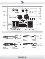
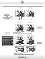
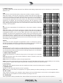
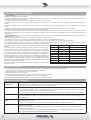
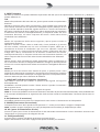
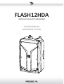
FLASH12HDA
ac ve processed loudspeaker
USER MANUAL
MANUALE D'USO
FCC COMPLIANCE NOTICE
This device complies with part 15 of the FCC rules. Opera on is subject to the following two condi ons:
(1) This device may not cause harmful interference, and
(2) this device must accept any interference received, including interference that may cause undesired opera on.
CAUTION: Changes or modifica ons not expressly approved by the party responsible for compliance could void
the user’s authority to operate the equipment.
NOTE: This equipment has been tested and found to comply with the limits for a Class B digital device, pursuant to
part 15 of the FCC Rules. These limits are designed to provide reasonable protec on against harmful interference in
a residen al installa on. This equipment generates, uses, and can radiate radio frequency energy and, if not installed
and used in accordance with the instruc on manual, may cause harmful interference to radio communica ons.
However, there is no guarantee that interference will not occur in a par cular installa on. If this equipment does
cause harmful interference to radio or television recep on, which can be determined by turning the equipment off
and on, the user is encouraged to try to correct the interference by one or more of the following measures:
• Reorient or relocate the receiving antenna.
• Increase the separa on between the equipment and receiver.
• Connect the equipment into an outlet on a circuit different from that to which the receiver is connected.
• Consult the dealer or an experienced radio/TV technician for help.
This marking shown on the product or its literature, indicates that it should not be disposed with other household wastes at the end of
its working life. To prevent possible harm to the environment or human health from uncontrolled waste disposal, please separate this
from other types of wastes and recycle it responsibly to promote the sustainable reuse of material resources. Household users should
contact either the retailer where they purchased this product, or their local government office, for details of where and how they can
take this item for environmentally safe recycling. Business users should contact their supplier and check the terms and condi ons of the
purchase contract. This product should not be mixed with other commercial wastes for disposal.
The lightning flash with arrowhead symbol within an equilateral triangle is intended to alert the user to the presence of uninsulated
“dangerous voltage” within the product’s enclosure, that may be of sufficient magnitude to cons tute a risk of electric shock to persons.
The exclama on point within an equilateral triangle is intended to alert the user to the presence of important opera ng and maintenance
(servicing) instruc ons in the literature accompanying the appliance.
The informa on contained in this publica on has been carefully prepared and checked. However no responsibility will be taken for any errors. All
rights are reserved and this document cannot be copied, photocopied or reproduced in part or completely without wri en consent being obtained
in advance from PROEL. PROEL reserves the right to make any aesthe c, func onal or design modifica on to any of its products without any prior
no ce. PROEL assumes no responsibility for the use or applica on of the products or circuits described herein.
Il marchio riportato sul prodo o o sulla documentazione indica che il prodo o non deve essere smal to con altri rifiu domes ci al
termine del ciclo di vita. Per evitare eventuali danni all’ambiente si invita l’utente a separare questo prodo o da altri pi di rifiu e di
riciclarlo in maniera responsabile per favorire il riu lizzo sostenibile delle risorse materiali. Gli uten domes ci sono invita a conta are
il rivenditore presso il quale è stato acquistato il prodo o o l’ufficio locale preposto per tu e le informazioni rela ve alla raccolta
differenziata e al riciclaggio per questo po di prodo o. Gli uten aziendali sono invita a conta are il proprio fornitore e verificare i
termini e le condizioni del contra o di acquisto. Questo prodo o non deve essere smal to unitamente ad altri rifiu commerciali.
Il simbolo del lampo con freccia in un triangolo equilatero intende avver re l'u lizzatore per la presenza di "tensioni pericolose" non isolate
all'interno dell'involucro del prodo o, che possono avere una intensità sufficiente a cos tuire rischio di scossa ele rica alle persone.
Il punto esclama vo in un triangolo equilatero intende avver re l'u lizzatore per la presenza di importan istruzioni per l'u lizzo e la
manutenzione nella documentazione che accompagna il prodo o.
Le informazioni contenute in questo documento sono state a entamente reda e e controllate. Tu avia non è assunta alcuna responsabilità per
eventuali inesa ezze. Tu i diri sono riserva e questo documento non può essere copiato, fotocopiato, riprodo o per intero o in parte senza
previo consenso scri o della PROEL. PROEL si riserva il diri o di apportare senza preavviso cambiamen e modifiche este che, funzionali o di
design a ciascun proprio prodo o. PROEL non assume alcuna responsabilità sull’uso o sul l’applicazione dei prodo o dei circui qui descri .
INDEX
INDICE
FCC COMPLIANCE NOTICE . . . . . . . . . . . . . . . . . . . 2
TECHNICAL SPECIFICATIONS . . . . . . . . . . . . . . . . . 3
FREQUENCY RESPONSE . . . . . . . . . . . . . . . . . . . . . 4
DIMENSIONS AND FLYING POINTS . . . . . . . . . . . . . 4
ACCESSORIES . . . . . . . . . . . . . . . . . . . . . . . . . . . . . 5
CONTROL PANEL (FIG.1) . . . . . . . . . . . . . . . . . . . . . 6
CONNECTIONS (FIG.2) . . . . . . . . . . . . . . . . . . . . . . 6
CONFIGURATION EXAMPLES (FIG.3) . . . . . . . . . . . 7
SAFETY AND PRECAUTIONS . . . . . . . . . . . . . . . . . . 8
IN CASE OF FAULT . . . . . . . . . . . . . . . . . . . . . . . . . . 8
TROUBLESHOOTING . . . . . . . . . . . . . . . . . . . . . . . . 8
CE CONFORMITY . . . . . . . . . . . . . . . . . . . . . . . . . . . 9
PACKAGING, SHIPPING AND COMPLAINT . . . . . . . 9
WARRANTY AND PRODUCTS RETURN . . . . . . . . . . 9
INSTALLATION AND DISCLAIMER . . . . . . . . . . . . . . 9
POWER SUPPLY AND MAINTENANCE . . . . . . . . . . 9
GENERAL INFORMATION . . . . . . . . . . . . . . . . . . . 10
INPUT AND CONTROL INSTRUCTIONS (FIG.1/2/3)10
SPECIFICHE TECNICHE . . . . . . . . . . . . . . . . . . . . . . 3
RISPOSTA IN FREQUENZA . . . . . . . . . . . . . . . . . . . . 4
DIMENSIONI E PUNTI DI SOSPENSIONE. . . . . . . . . 4
ACCESSORI . . . . . . . . . . . . . . . . . . . . . . . . . . . . . . . 5
PANNELLO DI CONTROLLO (FIG.1) . . . . . . . . . . . . . 6
CONNESSIONI (FIG.2) . . . . . . . . . . . . . . . . . . . . . . . 6
ESEMPI CONFIGURAZIONI (FIG.3) . . . . . . . . . . . . . 7
AVVERTENZE PER LA SICUREZZA . . . . . . . . . . . . . 12
IN CASO DI GUASTO . . . . . . . . . . . . . . . . . . . . . . . 12
PROBLEMATICHE COMUNI . . . . . . . . . . . . . . . . . . 12
CONFORMITÀ CE . . . . . . . . . . . . . . . . . . . . . . . . . . 13
IMBALLAGGIO, TRASPORTO E RECLAMI . . . . . . . 13
GARANZIE E RESI . . . . . . . . . . . . . . . . . . . . . . . . . 13
INSTALLAZIONE E LIMITAZIONI D’USO . . . . . . . . . 13
ALIMENTAZIONE E MANUTENZIONE . . . . . . . . . . 13
INFORMAZIONI GENERALI . . . . . . . . . . . . . . . . . . 14
ISTRUZIONI INGRESSI E CONTROLLI (FIG.1/2/3) . 14
TECHNICAL SPECIFICATIONS
SPECIFICHE TECNICHE
MODEL
FLASH12HDA
MODELLO
FLASH12HDA
System type
2-way vented
Sistema
2 vie bass-reflex
Low Frequency Device
12” CELESTION woofer with 3"VC
Altoparlante bassi
woofer 12" CELESTION - 3" VC
High Frequency Device
1” CELESTION compression driver with 1.75"VC
Altoparlante al
driver a compressione 1" CELESTION - 1.75" VC
Angular Coverage
90° H x 60° V
Copertura angolare
90° H x 60° V
Frequency response
50 Hz - 20 kHz
Risposta in Frequenza
50 Hz - 20 kHz
Max SPL at 1mt (peak)
128 dBspl
SPL massima a 1m (picco)
128 dBspl
Amplifier Con nuous
Power
HF: 100 W Class AB
LF: 500 W Class D with SMPS
Potenza Con nua
Amplificatore
Al : 100 W Classe AB
Bassi: 500 W Classe D con SMPS
Processing
96 KHz, 40 bit floa ng point CORE DSP
Processore DSP
96 KHz, 40 bit floa ng point CORE DSP
Input Impedance
30 kohm balanced / 15 kohm unbalanced
Impedenza ingresso
30 kohm sbilanciato / 15 kohm bilanciato
Input Sensi vity
LINE: +4 dBu / MIC: +34 dBu
Sensibilità nom. ingresso
LINE: +4 dBu / MIC: +34 dBu
Controls
LEVEL, MIC/LINE selector, PRESET selector (FLAT,
DJ, SPEECH, MONITOR), GND li
Controlli
LEVEL, sele ore MIC/LINE, sele ore PRESET (FLAT,
DJ, SPEECH, MONITOR), GND li
Connectors
INPUT: COMBO (XLR-F/JACK)
LINK: XLR-M
Conne ori
INPUT: COMBO (XLR-F/JACK)
LINK: XLR-M
Power Supply
230 VAC or 120 VAC - 50/60 Hz
Tensione alim. di rete
230 VAC o 120 VAC - 50/60 Hz
Maximum Consump on
650 VA
Consumo massimo
650 VA
Rated Consump on*
200 VA
Consumo nominale*
200 VA
Construc on
Reinforced hi density Polypropylene
Costruzione
Polipropilene
Cabinet Colour
Black
Colore
Nero
Flying System
4 x M10
Sistema di sospensione
4 x M10
Pole Adapter
1 x bo om
Flangia per suppor
1 x so o
Handles
2 x sides, 1 x top
Maniglie
2 x ai la , 1 x sopra
Monitor taper
42°
Inclinazione monitor
42°
Weight
19.4 Kg (47.7 lb)
Peso
19.4 Kg
Dimensions (W x H x D)
390 x 630 x 360 mm
Dimensioni (LxAxP)
390 x 630 x 360 mm
* Rated consump on is measured with pink noise with a crest factor of 12 dB,
this can be considered a standard music program.
* Il consumo nominale è misurato con un rumore rosa con un fa ore di cresta
di 12 dB, considerato come un programma standard di musica.
3
RISPOSTA IN FREQUENZA
90°
FREQUENCY RESPONSE
60°
120.0
dBSPL
2000 Hz
4000 Hz
8000 Hz
16000 Hz
30°
110.0
-90°
90°
-30
100.0
-6
-30°
30°
dB
HORIZONTAL
HORN POLAR PLOT
Q = 5.3 DI = 7.3
-30°
2000 Hz
4000 Hz
8000 Hz
16000 Hz
0
50
100
200
500
1k
2k
Hz
5k
10k
VERTICAL
HORN POLAR PLOT
Q = 7.0 DI = 8.5
20k
-90°
70.0
40
-60°
80.0
DIMENSIONS AND FLYING POINTS
DIMENSIONI E PUNTI DI SOSPENSIONE
42°
36 cm
14.2"
M10 Flying Point
63 cm
24.8"
39 cm
15.4"
Pole Adapter
M10 Flying Point
0
-6
-12
90.0
4
dB
-12
-18
-60°
60°
-24
-30
-24
-18
ACCESSORIES
ACCESSORI
KP210
Adjustable speaker pole for speaker-subwoofer separa on
with terminal pieces Ø 35 mm. Supplied with a bolt
locking mechanism incorpora ng a steel pin for extra
safety. Adjustment: 825 - 1320 mm.
FRE300BK
Professional aluminium floor-stand for speaker with
terminal pieces Ø 35mm. Supplied with a screw locking
system, a steel safety pin and “Aircushioned” air-damped
release device to grant a flexible, fast and easy adjustment.
Adjustment: 1470-2180 mm.
AC169
Black galvanized steel eyebolt MA10 for flying mount.
KPTFL12
C-shape metal bracket for wall mount with 4 step of 15°
combined with 2 step of 40°.
KPTNX04
Horizontal and Ver cal adjustable metal bracket for wall
mount, bar length 25 cm, 12.5° 4 step vert. aiming, 10°
7 step hor. aiming, must be used in conjunction with
KPTFL12.
PLH300
Single aluminium coupler with M12 bolt, always use two
couplers with the KPTL12 for each speaker.
COVERFL12
Heavy duty cover for carrying.
KP210
Supporto distanziatore cassa-subwoofer regolabile in
acciaio con terminali Ø 35mm. Dotato di meccanismo di
chiusura a vite con pin di sicurezza in acciaio. Regolazione:
825 - 1320 mm.
FRE300BK
Supporto professionale in alluminio da pavimento con
terminali Ø 35mm. Con sistema di blocco a vite, pin di
sicurezza in acciaio e disposi vo di smorzamento ad aria
per la massima velocità e facilità di regolazione.
Regolazione: 1470-2180 mm.
AC169
Golfare in acciaio zincato nero MA10 per sospensione.
KPTFL12
Supporto in metallo a C per montaggio a muro con 4 passi
da 15° combinabili con 2 passi a 40°.
KPTNX04
Staff a in metallo regolabile in orizzontale e ver cale per
montaggio a muro, lunghezza barra 25 cm, 4 passi a 12.5°
in ver cale e 7 passi a 10° in orizzontale, deve essere usata
con l'accessorio KPTFL12.
PLH300
Accoppiatore per truss in alluminio con bullone M12,
usarne sempre due insieme all'accessorio KPTFL12.
COVERFL12
Copertura di protezione per il trasporto.
FRE300BK
AC169
KPTFL12
KPTNX04
KP210
PLH300
COVERFL12
5
CONTROL PANEL (FIG.1)
PANNELLO DI CONTROLLO (FIG.1)
CONNECTIONS (FIG.2)
CONNESSIONI (FIG.2)
INPUT
Balanced male XLR
hot
tip - hot
cold
ring - cold
ground
sleeve - ground
INPUT (ingresso)
XLR bilanciato maschio
INPUT
Jack (balanced)
ground
LINK (output)
Balanced female XLR
6
INPUT (ingresso)
Jack (bilanciato)
tip - hot
cold
cold
hot
ground
LINK (uscita)
XLR bilanciato femmina
INPUT
Jack (unbalanced)
*note: connect both cold and ground
to make cable from balanced to unbalanced
INPUT (ingresso)
Jack (sbilanciato)
*nota: connettere insieme cold e ground
per cavi da bilanciato a sbilanciato
CONFIGURATION EXAMPLES (FIG.3)
ESEMPI CONFIGURAZIONI (FIG.3)
FLASH12HDA
(mic in)
single voice system
FLASH12HDA
(mic in)
single voice system
SET THE EQ PRESET ON “SPEECH”
AND LINE/MIC ON “MIC”
minimal
conference
system
dynamic
microphone
PROEL suggested
types:
DM580 - DM586 - DM226
DM220 - DM800
or
WM wireless mic
LEFT
FLASH12HDA
RIGHT
FLASH12HDA
basic system
2x FLASH12HDA
600W x2 (1200W)
L
PROEL suggested
equipment:
M-series mixer
R
LEFT
FLASH12HDA (sat)
+ SW115HA (sub)
L
RIGHT
FLASH12HDA (sat)
+ SW115HA (sub)
SUB+SAT system
2x SW115HA
+
2x FLASH12HDA
500W x2 + 600W x2
(2200W)
L
R
7
SAFETY AND PRECAUTIONS
•
CAUTION: before using this product read carefully the following safety instruc ons. Take a look of this manual en rely and preserve it for
future reference.
When using any electric product, basic precau ons should always be taken, including the following:
– To reduce the risk, close supervision is necessary when the product is used near children.
– Protect the apparatus from atmospheric agents and keep it away from water, rain and high humidity places.
– This product should be site away from heat sources such as radiators, lamps and any other device that generate heat.
– This product should be located so that its loca on or posi on does not interfere with its proper ven la on and hea ng dissipa on.
– Care should be taken so that objects and liquids do not go inside the product.
– The product should be connected to a power supply mains line only of the type described on the opera ng instruc ons or as marked on the
product. Connect the apparatus to a power supply using only power cord included making always sure it is in good condi ons.
–
WARNING: The mains plug is used as disconnect device, the disconnect device shall remain readily operable.
– Do not cancel the safety feature assured by means of a polarized line plug (one blade wider than the other) or with a earth connec on.
– Make sure that power supply mains line has a proper earth connec on.
– Power supply cord should be unplugged from the outlet during strong thunderstorm or when le unused for a long period of me.
– Do not place objects on the product’s power cord or place it in a posi on where anyone could trip over, walk on or roll anything over it. Do not
allow the product to rest on or to be installed over power cords of any type. Improper installa ons of this type create the possibility of fire hazard
and/or personal injury.
– This product may be capable of producing sound levels that could cause
on Per Day
Sound Level dBA
Typical
permanent hearing loss. Exposure to extremely high noise levels may cause Dura
In Hours
Slow Response
Example
permanent hearing loss. Individuals vary considerably in suscep bility to noise8
90
Duo in small club
induced hearing loss, but nearly everyone will lose some hearing if exposed
6
92
to sufficiently intense noise for a period of time. The U.S. Government’s
Occupational Safety and Health Administration (OSHA) has specified the 4
95
Subway Train
permissible noise level exposures shown in the following chart. According to 3
97
OSHA, any exposure in excess of these permissible limits could result in some
2
100
Very loud classical music
hearing loss. To ensure against poten ally dangerous exposure to high sound
1.5
102
pressure levels, it is recommended that all persons exposed to equipment
capable of producing high sound pressure levels use hearing protectors while 1
105
Traffic noise
the equipment is in opera on. Ear plugs or protectors in the ear canals or over 0.5
110
the ears must be worn when opera ng the equipment in order to prevent
0.25 or less
115
Loudest parts at a rock concert
permanent hearing loss if exposure is in excess of the limits set forth here. Keep
your's a en on that children and pets are more suscep ble to excessive noise
levels.
IN CASE OF FAULT
•
–
–
–
–
–
•
In case of fault or maintenance this product should be inspected only by qualified service personnel when:
There is a flaw either in the connec ons or in the supplied connec ng cables.
Liquids have spilled inside the product.
The product has fallen and been damaged.
The product does not appear to operate normally or exhibits a marked change in performance.
The product has been lost liquids or gases or the enclosure is damaged.
Do not operate on the product, it has no user-serviceable parts inside, refer servicing to an authorized maintenance centre.
TROUBLESHOOTING
8
No Power
• The loudspeaker's "POWER" switch is off.
• Make sure the mains AC outlet is live (check with a tester or a lamp).
• Make sure the mains plug is securely plugged into mains AC outlet.
No Sound
• Is the input LEVEL control for the channel turned up?
• Is the SIGNAL LED illuminated? If not check if your signal level is too low or check the signal cable, mixer and other
equipment se ng and cabling.
• Are you sure your signal cables works properly? check it using a cable tester or replacing with a new one.
• Is the SPEAKON cable connector correctly inserted? turn it clockwise un l it clicks.
• Are you sure your power cable works properly? check it using a cable tester or replacing with a new one.
Distorted Sound
• Input signal level is too high. Turn down your level controls.
NOTE: The loudspeakers should never be operated at a level which causes the amplifier Clip LEDs to illuminate
constantly.
Different channel
level
• Check if are using a balanced cable for one channel and an unbalanced one for the other, as this would cause a
considerable difference in channel levels.
• Be sure that your loudspeaker system is fully connected and both loudspeakers have the same impedance.
Noise / Hum
• Enable GND LIFT bu on on rear panel, if the problem persist press all GND LIFT bu ons for all system's amplifiers.
• Whenever possible, preferably use only balanced cables. Unbalanced lines may also be used but may result in noise
over long cable runs.
• Some mes it helps to plug all audio equipment into the same AC circuit so they share a common ground.
CE CONFORMITY
• Proel products comply with direc ve 2004/108/EC (EMC), as stated in EN 55103-1 and EN 55103-2 standards and with direc ve 2006/95/CE
(LVD), as stated in EN 60065 standard.
• Under the EM disturbance, the ra o of signal-noise will be changed above 10dB.
PACKAGING, SHIPPING AND COMPLAINT
• This unit package has been submi ed to ISTA 1A integrity tests. We suggest you control the unit condi ons immediately a er unpacking it.
• If any damage is found, immediately advise the dealer. Keep all unit packaging parts to allow inspec on.
• Proel is not responsible for any damage that occurs during shipment.
• Products are sold “delivered ex warehouse” and shipment is at charge and risk of the buyer.
• Possible damages to unit should be immediately no fied to forwarder. Each complaint for package tampered with should be done within eight
days from product receipt.
WARRANTY AND PRODUCTS RETURN
• Proel products have opera ng warranty and comply their specifica ons, as stated by manufacturer.
• Proel warrants all materials, workmanship and proper opera on of this product for a period of two years from the original date of purchase. If
any defects are found in the materials or workmanship or if the product fails to func on properly during the applicable warranty period, the owner
should inform about these defects the dealer or the distributor, providing receipt or invoice of date of purchase and defect detailed descrip on.
This warranty does not extend to damage resul ng from improper installa on, misuse, neglect or abuse. Proel S.p.A. will verify damage on returned
units, and when the unit has been properly used and warranty is s ll valid, then the unit will be replaced or repaired. Proel S.p.A. is not responsible
for any "direct damage" or "indirect damage" caused by product defec veness.
INSTALLATION AND DISCLAIMER
• Proel products have been expressly designed for audio applica on, with signals in audio range (20Hz to 20kHz). Proel has no liability for damages
caused in case of lack of maintenance, modifica ons, improper use or improper installa on non-applying safety instruc ons.
• The installa on of these speakers is provided for indoors, in case of use outdoors be sure that the speakers are installed correctly in a safe
loca on protected from wind, rain and humidity. To avoid performance deteriora on of mechanical, acous cs and electrical parts is not advisable
to leave these speakers exposed outdoors for a long period of me, so we suggest a temporary installa on for the limited sound events.
• The installa on of these speakers is provided for floor or by means of specific stands able to support their weight. Therefore avoid installa on
on unstable elements such as: furniture, chairs and vibrant surfaces as stages or other speakers without appropriate fix point specifically designed
to avoid speaker movement. Then avoid the use of inadequate supports, we suggest to use PROEL stands and accessories only.
• In case of the speakers are provided of rigging points: DO NOT SUSPEND THE SPEAKERS FROM THE HANDLES, use exclusively these rigging points.
Consult professional rigger or structural engineers prior to suspending loudspeakers from a structure not intended for that use. Always know the
working load limit of the structure suppor ng the loudspeakers. Always make sure that the rigging hardware minimum ra ng is at least five mes
the actual load, speakers and rigging hardware.
• In case of suspended installa ons of ac ve loudspeakers where is not possible to turn on and off the speakers from their appropriate switches,
we recommend to install switches on the mains lines, for this purpose consult an expert electrician for the exact dimension of wiring.
• Locate the speakers as far away as possible from radio or television receivers or other sensi ve equipment. These speakers have a strong
magne c field which can induce hum and noise into unshielded devices that are located nearby with consequent deteriora on of recep on of
image and sound.
• Proel S.p.A. reserves the right to change these specifica ons at any me without no ce.
• Proel S.p.A. declines any liability for damages to objects or persons caused by lacks of maintenance, improper use, installa on not performed
with safety precau ons and at the state of the art.
POWER SUPPLY AND MAINTENANCE
• Clean only with dry cloth.
• Check periodically that the slots for its proper ven la on and hea ng dissipa on are not obstructed by dust, remove the dust using a dry brush
or a compressed air gun.
• The amplified loudspeakers of Proel have been designed with CLASS I construc on and must be connected always to a mains socket outlet with
a protec ve earth connec on (the third grounding prong).
• Before connec ng the product to the mains outlet make certain that the mains line voltage matches that shown on the rear of the product, a
tolerance of up to ±10% is acceptable.
• Inside the amplified loudspeakers are present special safety devices such as:
9 Transformer and amplifier over-hea ng protec on.
9 Protec on against excessive power applied at each speaker.
•
THE REPLACEMENT OF FUSES INSIDE THE APPARATUS MUST BE MADE ONLY BY QUALIFIED PERSONNEL.
•
CHECK THE CONDITION OF THE PROTECTION FUSE, ACCESSIBLE OUTWARD, ONLY WITH THE APPARATUS SWITCHED OFF AND DISCONNECTED
FROM THE MAINS LINE OUTLET.
•
REPLACE THE PROTECTION FUSE ONLY WITH SAME TYPE AS SHOWN ON THE PRODUCT.
•
IF AFTER THE SUBSTITUTION, THE FUSE INTERRUPTS AGAIN THE APPARATUS WORKING, DO NOT TRY AGAIN THEN CONTACT THE PROEL
SERVICE CENTRE.
9
GENERAL INFORMATION
Thank you for having chosen a PROEL product.
FLASH12HDA is an ac ve full-range 2-way system featuring high-grade CELESTION transducers and a DSP-controlled
lightweight amplifier module in a sturdy polypropylene cabinet. The transducers employed include a 1” compression
driver with a 1.75" voice coil on a wide constant coverage horn, designed for providing an extended response and low
distor on levels, and a high-power 12” woofer with a 3” voice coil.
The profile of the cabinet allows the use of the enclosure also as a stage monitor, whereas four M10 suspension points
are provided for installa on in a variety of posi ons using the op onal accessories available. Two convenient aluminium
handles, plus a third on top of the cabinet, make for easy handling and transporta on.
The amplifier module includes a 100 W CLASS AB amplifier for the HF sec on and a 500 W CLASS D amplifier with SMPS
for the LF sec on. A built-in DSP sec on features state-of-the-art signal processing with 40 bit floa ng point resolu on
and 24 bit AD/DA converters, for a superior sonic performance. Advanced func ons include full parametric EQ for the
system fine tuning, delay lines for speaker alignment, up to 48 dB/oct. crossover filters, three bands of dynamic EQ,
compressors/limiters for protec ng the transducers against distor on and power overloads. 4 different PRESETS (FLAT,
DJ, SPEECH, MONITOR) op mized for using the system in different applica ons are also available.
INPUT AND CONTROL INSTRUCTIONS (FIG. 1 / 2 / 3)
1. LINE/MIC IN (combo XLR-JACK input)
This is a female combo connector, which accepts a XLR or a JACK plug from almost any type of equipment with a
balanced or unbalanced outputs. The XLR input is wired as follows:
Pin 1 = shield or ground
Pin 2 = + posi ve or "hot"
Pin 3 = - nega ve or "cold"
The JACK input is wired as follows:
Tip = + posi ve or "hot"
Ring = - nega ve or "cold"
Sleeve = shield or ground
When connec ng an unbalanced signal, wire them as follows:
Pin2 / Tip = + posi ve or "hot"
Pin 1-3 / Sleeve = shield or ground
NOTE: whenever possible, use always balanced cables. Unbalanced lines may also be used but may result in noise over
long cable runs. In any case, avoid using a balanced cable for one channel and an unbalanced one for the other.
2. LINK (XLR output)
This is a male XLR connector, it is connected in parallel with the respec ve LINE IN input, so the LINK is wired as LINE IN
input. Connect these to the inputs of other powered speakers to make an array.
3. GND LIFT switch
This switch li the ground of the balanced audio inputs from the earth-ground of the amplifier. If you have HUM noise
problem on one or more loudspeaker try to change the posi on of these switches (o en all up or all down for all the
amplifiers in the system). Please note that to have an effect all cables must be balanced.
4. MIC / LINE switch
This switch adjusts the gain of the LINE/MIC input varying the sensi vity between MIC, suited to connect a microphone,
and LINE, suited to connect a device with high level output like a MIXER, a CD player etc.
NOTE: do not use the MIC sensi vity to "pump up" the volume with the LINE level equipment, in order to avoid the AD
converter satura on that could produce very annoying distor on.
5. LEVEL control
Rotary level control: it a enuates the level of the signal sent to the LINE input. The a enua on ranges from “0” fully
closed (the signal is completely a enuated) to “10” fully open, nominal level (the signal is not a enuated in any way,
so is fed to the internal amplifier at the same level at which it arrives on input).
10
6. PRESET selector
This switch allows the selec on between four different DSP se ngs (equalisa on curves, dynamics etc.), suited to four
different uses.
FLAT
Suited for live sound reinforcement, this preset includes a dynamic equalizer.
When the system is used at low or mid level, the deep lows and the top highs are
enhanced, resul ng in an deep and detailed response, ideal for the reproduc on
vocals and live instruments. When the level of the signal sent to the amplifier is
increased and it approaches the limiter ac on, the enhancement of low and high
frequencies is reduced, thus increasing the dynamics and the efficiency of the
whole system. Together with that, the mid-high frequencies are slighlty decreased,
thus reducing the harshness that can occur when the sound is very loud and
making it more enjoyable.
120.0
dBSPL
110.0
100.0
90.0
80.0
70.0
40
50
100
200
500
1k
2k
Hz
5k
10k
20k
50
100
200
500
1k
2k
Hz
5k
10k
20k
50
100
200
500
1k
2k
Hz
5k
10k
20k
120.0
dBSPL
DJ
Suited for the reproduc on of recorded music, this preset includes a dynamic
equalizer.
When the system is used at low or mid level, the deep lows and the top highs are
enhanced, resul ng in an richer and brighter response, ideal for the reproduc on
of background music or for a DJ set. When the level of the signal sent to the
amplifier is increased and it approaches the limiter ac on, the enhancement of low
and high frequencies is reduced, thus increasing the dynamics and the efficiency
of the whole system. Together with that, the mid-high frequencies are slightly
decreased, thus reducing the harshness that can occur when the sound is very loud
and making it more enjoyable.
110.0
100.0
90.0
80.0
70.0
40
120.0
dBSPL
110.0
100.0
SPEECH
This preset has been designed for applica ons (such as conferences) where a
dynamic microphone is directly connected to the speaker input and it provides the
correct equaliza on for enhancing the human voice intelligibility.
MONITOR
Suited for the use of the system as a stage monitor, in this preset the deep lows
are a enuated in order to compensate the floor posi on, the mid-low frequencies
are enhanced for a be er presence and the mid-high frequencies are reduced for
an improved feedback rejec on.
90.0
80.0
70.0
40
120.0
dBSPL
110.0
100.0
90.0
7. SIGN / LIMIT indicator
80.0
GREEN LED illuminates to indicate the presence of the signal at the amplifier
input.
RED LED illuminates when the internal amplifier's output is limited or when the
input AD converter clips.
NOTE: When this LED flashes reduce the input signal level.
NOTE: If you hear annoying and excessive distor on check the MIC/LINE switch posi on, most probably you are sending
to the speaker a high line level signal using the MIC sensi vity, so switch it to LINE sensi vity.
70.0
40
50
100
200
500
1k
2k
Hz
5k
10k
20k
8. ON indicator
GREEN LED: when lighted indicates that the amplifier has been turned on and AC power is available.
9. POWER switch
Speaker is "ON" when the switch is in the "I" posi on.
NOTE: When you shut down your equipment, turn off the speaker first. When powering up, turn on the speaker last.
10. AC~ socket
Here’s where you plug in your speaker’s mains supply cord. You should always use the mains cord supplied with the
speaker. Be sure your speaker is turned off before you plug in the cord.
11. FUSE holder
Here is placed the mains protec on fuse. Please follow the instruc ons on page 9 of this manual to replace it.
11
AVVERTENZE PER LA SICUREZZA
•
ATTENZIONE: Durante le fasi di uso o manutenzione, devono essere prese alcune precauzioni onde evitare danneggiamen alle stru ure
meccaniche ed ele roniche del prodo o.
Prima di u lizzare il prodo o, si prega di leggere a entamente le seguen istruzioni per la sicurezza. Prendere visione del manuale d’uso e
conservarlo per successive consultazioni:
– In presenza di bambini, controllare che il prodo o non rappresen un pericolo.
– Posizionare l’apparecchio al riparo dagli agen atmosferici e a distanza di sicurezza dall’acqua, dalla pioggia e dai luoghi ad alto grado di
umidità.
– Collocare o posizionare il prodo o lontano da fon di calore quali radiatori, griglie di riscaldamento e ogni altro disposi vo che produca
calore.
– Collocare o posizionare il prodo o in modo che non ci siano ostruzioni alla sua propria ven lazione e dissipazione di calore.
– Evitare che qualsiasi ogge o o sostanza liquida entri all’interno del prodo o.
– Il prodo o deve essere connesso esclusivamente alla rete ele rica delle cara eris che descri e nel manuale d’uso o scri e sul prodo o,
usando esclusivamente il cavo rete in dotazione e controllando sempre che sia in buono stato, in par colare la spina e il punto in cui il cavo esce
dal prodo o.
–
ATTENZIONE: Se il cavo rete viene scollegato dall'apparecchio per spegnerlo, il cavo rete rimarrà opera vo in quanto la sua spina è ancora
collegata alla rete ele rica.
– Non annullare la sicurezza garan ta dall'uso di spine polarizzate o con messa a terra.
– Fare a enzione che il punto di alimentazione della rete ele rica sia dotato di una efficiente presa di terra.
– Disconne ere il prodo o dalla rete ele rica durante for temporali o se non viene usato per un lungo periodo di tempo.
– Non disporre ogge sul cavo di alimentazione, non disporre i cavi di alimentazione e segnale in modo che qualcuno possa incianparci. Altresì
non disporre l’apparecchio sui cavi di altri appara . Installazioni inappropriate
Esempio
di questo po possono creare la possibilità di rischio di incendio e/o danni alle Ore di esposizione Livello sonoro in dBA
giornaliera
costante di tempo SLOW
Tipico
persone.
90
Duo acus co in un piccolo club
– Questo prodo o può essere capace di produrre livelli sonori che possono 8
causare perdite d’udito permanen . Si raccomanda di evitare l’esposizione 6
92
ad alti livelli sonori o livelli non confortevoli per lunghi periodi di tempo. 4
95
Treno metropolitano
Se si notano perdite d’udito o acufeni (fischi) consultare un audiologo. La
3
97
sensibilità alla perdita di udito causata da eccessiva esposizione al rumore varia
100
Musica classica molto forte
considerevolmente da individuo a individuo, ma mediamente ciascuno può 2
accusare perdita di udito se esposto al rumore per un certo periodo di tempo. 1.5
102
Come suggerimento viene riportata la tabella dei tempi massimi di esposizione 1
105
Rumore da traffico urbano intenso
giornaliera al rumore al fine di evitare perdite di udito, fonte della tabella è l'ente
0.5
110
per la salute degli Sta Uni (OSHA).
115
Parte più rumorosa di un concerto rock
Si fa presente inoltre che sia i bambini che gli animali domes ci sono più sensibili 0.25 or less
al rumore intenso.
IN CASO DI GUASTO
•
–
–
–
–
–
•
In caso di guasto o manutenzione questo prodo o deve essere ispezionato da personale qualificato quando:
Ci sono dife sulle connessioni o sui cavi di collegamento in dotazione.
Sostanze liquide sono penetrate all’interno del prodo o.
Il prodo o è caduto e si è danneggiato.
Il prodo o non funziona normalmente esibendo una marcato cambio di prestazioni.
Il prodo o perde sostanze liquide o gassose o ha l’involucro danneggiato.
Non intervenire sul prodo o. Rivolgersi a un centro di assistenza autorizzato Proel.
PROBLEMATICHE COMUNI
12
Assenza di
alimentazione
• L'interru ore dell'altoparlante è spento.
• Accertarsi che ci sia effe vamente tensione sulla presa di corrente (controllare con un tester o una lampada).
• Accertarsi che la spina di rete sia saldamente inserita nella presa.
Nessun Suono
• È il controllo di livello LINE IN girato al massimo?
• È acceso il LED di segnale? Se no, controllate se il livello di segnale sia troppo basso o controllate il cavo di segnale,
le impostazioni e i cablaggi di mixer o altri apparecchi collega .
• Sei sicuro che il cavo di segnale sia in buono stato? controlla il cavo con un tester oppure sos tuiscilo con un'altro.
Suono Distorto
• Il livello del segnale di ingresso è troppo alto, abbassare i controlli del livello.
NOTA: L'altoparlante non deve mai lavorare con livelli che fanno illuminare in modo pressoché costante il LED rosso
dell'amplificatore.
Livello differente sui
canali
• Controllare se si stanno usando cavi bilancia su un canale e sbilancia sull'altro, ciò può comportare una notevole
differenza di livello sui canali.
• Assicurarsi che gli altoparlan siano completamente collega e abbiano la medesima impedenza.
Rumore / Ronzio
• Abilitare l'interru ore GND LIFT sul pannello posteriore, se il problema persiste premere i GND LIFT su tu gli
amplificatori del sistema.
• Qualora possibile, usare preferibilmente solo cavi bilancia . Cavi sbilancia possono essere usa ma risultano
rumorosi su lunghe distanze.
• Talvolta può essere di aiuto alimentare tu o l'equipaggiamento audio collegandolo dalla stessa linea di corrente
AC, in modo che tu gli appara condividano la stessa presa di terra.
CONFORMITÀ CE
• I Prodo Proel sono conformi alla dire va 2004/108/EC (EMC), secondo gli standard EN 55103-1 ed EN 55103-2 ed alla dire va 2006/95/CE
(LVD), secondo lo standard EN 60065.
• Se so oposto a disturbi EM, il rapporto segnale-rumore può essere superiore a 10dB.
IMBALLAGGIO, TRASPORTO E RECLAMI
• L’imballo è stato so oposto a test di integrità secondo la procedura ISTA 1A. Si raccomanda di controllare il prodo o subito dopo l’apertura
dell’imballo.
• Se vengono riscontra danni informare immediatamente il rivenditore. Conservare quindi l’imballo completo per perme erne l’ispezione.
• Proel declina ogni responsabilità per danni causa dal trasporto.
• Le merci sono vendute “franco nostra sede” e viaggiano sempre a rischio e pericolo del distributore.
• Eventuali avarie e danni dovranno essere contesta al ve ore. Ogni reclamo per imballi manomessi dovrà essere inoltrato entro 8 giorni dal
ricevimento.
GARANZIE E RESI
• I Prodo Proel sono provvis della garanzia di funzionamento e di conformità alle proprie specifiche, come dichiarate dal costru ore.
• La garanzia di funzionamento è di 24 mesi dopo la data di acquisto. I dife rileva entro il periodo di garanzia sui prodo vendu , a ribuibili a
materiali dife osi o dife di costruzione, devono essere tempes vamente segnala al proprio rivenditore o distributore, allegando evidenza scri a
della data di acquisto e descrizione del po di dife o riscontrato. Sono esclusi dalla garanzia dife causa da uso improprio o manomissione. Proel
SpA constata tramite verifica sui resi la dife osità dichiarata, correlata all’appropriato u lizzo, e l’effe va validità della garanzia; provvede quindi
alla sos tuzione o riparazione dei prodo , declinando tu avia ogni obbligo di risarcimento per danni dire o indire eventualmente derivan
dalla dife osità.
INSTALLAZIONE E LIMITAZIONI D’USO
• I Prodo Proel sono des na esclusivamente ad un u lizzo specifico di po sonoro: segnali di ingresso di po audio (20Hz-20kHz). Proel declina
ogni responsabilità per danni a terzi causa da mancata manutenzione, manomissioni, uso improprio o installazione non eseguita secondo le
norme di sicurezza.
• L'installazione di ques altoparlan è prevista per uso interno, in caso di u lizzo all'esterno assicurarsi che gli altoparlan siano installa
corre amente in un luogo sicuro e prote o dal vento, pioggia e umidità. Al fine di non deteriorarne le prestazioni meccaniche, acus che ed
ele riche non è consigliato lasciare ques altoparlan espos all'aperto per lunghi periodi di tempo, si consiglia pertanto una installazione
temporanea all'evento da sonorizzare.
• L'installazione di ques altoparlan è prevista a pavimento o tramite specifici suppor adegua al peso da sostenere. Pertanto evitare
l'installazione su elemen instabili quali: mobili, sedie e superfici vibran quali palchi e altri altoparlan non dota di fissaggi a a evitare
spostamen dell'altoparlante. Quindi evitare di u lizzare suppor non adegua , si consiglia di usare solo i suppor suggeri da PROEL.
• Qualora gli altoparlan siano muni di pun di fissaggio per la sospensione: NON SOSPENDERE GLI ALTOPARLANTI DALLE MANIGLIE usare
esclusivamente ques pun di fissaggio. Consultare a rezzis professionis o ingegneri stru urali prima di sospendere altoparlan da stru ure non
intese per questo specifico scopo. Non superare il limite di carico della stru ura che sosterrà gli altoparlan . Assicurarsi che tu e le meccaniche
di sostegno siano in grado di sopportare un peso almeno 5 volte superiore al carico degli altoparlan incluse le meccaniche di sospensione.
• Nel caso di installazioni sospese di altoparlan a vi in cui non sia possibile l'uso dei singoli interru ori degli altoparlan per l'accensione e lo
spegnimento dei medesimi, si raccomanda l'installazione di interru ori sulle linee di alimentazione della rete ele rica, a tale proposito consultare
un esperto ele ricista per il corre o dimensionamento dell'impianto ele rico.
• Installare ques altoparlan il più lontano possibile da radioricevitori e televisori. Un altoparlante installato in prossimità di ques appara può
causare interferenza e rumore con conseguente degrado della ricezione di immagini e suoni.
• La Proel S.p.a. si riserva di modificare il prodo o e le sue specifiche senza preavviso.
• Proel declina ogni responsabilità per danni a terzi causa da mancata manutenzione, manomissioni, uso improprio o installazione non eseguita
secondo le norme di sicurezza e a regola d'arte.
ALIMENTAZIONE E MANUTENZIONE
• Pulire il prodo o unicamente con un panno asciu o.
• Controllare periodicamente che le aperture di raffredamento non siano ostruite da accumuli di polvere, provvedere alla rimozione della polvere
mediante un pennello o aria compressa.
• Gli altoparlan amplifica della Proel sono costrui in CLASSE I e prevedono sempre il collegamento mediante presa di corrente con terminale
di terra di protezione (terzo terminale di terra).
• Prima di collegare l'apparecchio alla presa di corrente, accertatevi che la tensione di rete corrisponda a quella indicata sul retro dell’apparato, è
consen to un margine del ±10% rispe o al valore nominale.
• Negli altoparlan amplifica sono presen anche i seguen disposi vi di sicurezza:
9 protezioni termiche del trasformatore e dell'amplificatore.
9 protezioni alla potenza erogata in eccesso ai singoli altoparlan .
•
LA SOSTITUZIONE DI FUSIBILI ALL'INTERNO DELL'APPARATO È CONSENTITO SOLAMENTE A PERSONALE QUALIFICATO.
•
CONTROLLARE LO STATO DEI FUSIBILI DI PROTEZIONE ESCLUSIVAMENTE AD APPARATO SPENTO E DISCONNESSO DALLA RETE ELETTRICA.
•
RIMPIAZZARE IL FUSIBILE DI PROTEZIONE ESCLUSIVAMENTE CON UN FUSIBILE CON LE MEDESIME CARATTERISTICHE RIPORTATE SUL
PRODOTTO.
•
SE DOPO LA SOSTITUZIONE, IL FUSIBILE INTERROMPE NUOVAMENTE IL FUNZIONAMENTO DELL'APPARATO, NON INSISTERE E CONTATTARE
IL SERVIZIO ASSISTENZA PROEL.
13
INFORMAZIONI GENERALI
Grazie per aver scelto un prodo o PROEL.
FLASH12HDA è un sistema a 2 vie che u lizza altoparlan CELESTION di elevata qualità e un modulo amplificatore con
DSP in una cabinet di polipropilene rinforzato. Gli altoparlan impiega sono un driver a compressione da 1" con bobina
da 1.75" su tromba a dire vità costante ed un woofer da 12" con bobina da 3".
Il profilo trapezoidale del cabinet ne perme e l'u lizzo anche in posizione da monitor. Sono disponibili qua ro pun
di sospensione file a M10 da u lizzarsi con gli accessori dedica all'installazione. Due comode maniglia laterali e una
superiore ne o mizzano il trasporto.
Il modulo amplificatore con alimentazione SMPS include una sezione da 100W in classe AB per gli al e un amplificatore
in classe D da 500W per i bassi. Il modulo è completato da una sezione DSP allo stato dell'arte con processamento a
40bit in virgola mobile e conver tori AD/DA a 24bit per o enere prestazioni sonore molto elevate. Le funzioni di cui
dispone includono equalizzatori parametrici, delay per l'allineamento degli altoparlan , filtri crossover, equalizzatore
dinamico, compressori e limiter per la riduzione della distorsione e la protezione degli altoparlan . Sono disponibili 4
PRESET differen (FLAT, DJ, SPEECH, MONITOR) o mizza per l'u lizzo del sistema nelle più svariate situazioni.
ISTRUZIONI INGRESSI E CONTROLLI (FIG. 1 / 2 / 3)
1. LINE/MIC IN (ingresso COMBO XLR/JACK)
Questo è un conne ore combinato XLR/JACK femmina che preleva il segnale da pra camente qualsiasi apparecchio
bilanciato o sbilanciato. Le terminazioni dell' ingresso XLR sono:
Pin 1 = schermo o massa
Pin 2 = + posi vo o "caldo"
Pin 3 = - nega vo o "freddo"
Le terminazioni dell' ingresso JACK sono:
Tip (punta) = + posi vo o "caldo"
Ring (anello) = - nega vo o "freddo"
Sleeve (manico o) = schermo o massa
E quando si collega un segnale sbilanciato, sono le seguen :
Pin2 / Tip (punta) = + posi vo o "caldo"
Pin 1-3 / Sleeve (manico o) = schermo o massa
NOTA: Se possibile, usare sempre cavi bilancia . Cavi sbilancia possono essere usa ma potrebbero dare problemi di
rumore se molto lunghi. In ogni caso, evitate di usare un cavo bilanciato per un canale e uno sbilanciato per l’altro.
2. LINK (XLR uscita)
Questo è un conne ore XLR maschio connesso in parallelo con il rispe vo conne ore LINE IN, perciò il LINK è terminato
come il LINE IN. Collegarlo ad altri altoparlan amplifica per realizzare un complesso sistema di rinforzo sonoro.
3. GND LIFT (interru ore sollevamento massa)
Questo interru ore solleva la massa degli ingressi audio bilancia dalla massa-terra dell'amplificatore. Se si hanno
problemi di ronzio su uno o più altoparlan provare a cambiare la posizione di ques interru ori: perché abbiano effe o
spesso occorre siano tu su o tu giù per tu gli amplificatori e che tu i cavi siano bilancia .
4. MIC / LINE (sele ore sensibilità linea / microfono)
Questo sele ore cambia la sensibilità dell'ingresso variando il guadagno tra: MIC, ada o a collegare dire amente un
microfono, e LINE, ada a a collegare una apparecchiatura con uscita di livello elevato quale un MIXER, un le ore CD,
etc.
NOTE: non usare la sensibilità MIC per "pompare" il volume con apparecchi a livello LINEA, per evitare la saturazione
dei conver tori AD che può produrre una distorsione molto sgradevole.
5. LEVEL (controllo di livello ingresso)
Controllo di livello rota vo: a enua il livello del segnale inviato all'amplificatore interno, l'a enuazione varia tra
completamente chiuso “0” a completamente aperto “10” o livello nominale (il segnale non è a enuato in nessun modo,
viene inviato all'amplificatore interno allo stesso livello con cui arriva all'ingresso).
14
6. PRESET sele ore
Perme e la selezione fra qua ro differen impostazioni del DSP (curva di equalizzazione, dinamica etc.), ada ate a
qua ro differen usi.
FLAT
Ada o alla riproduzione del suono dal vivo, questo preset include un equalizzatore
dinamico.
Quando il sistema è usato a bassi o medi livelli, i bassi profondi e gli estremi al
sono esalta , risultando cosi una profonda e de agliata risposta, ideale per le voci
e gli strumen . Quando il livello del segnale aumenta e si avvicina all'intervento
dei limiter, l'esaltazione dei bassi e degli al si riduce, aumentando cosi la dinamica
e l'efficienza del sistema. Contemporaneamente, le frequenze medio alte sono
lievemente diminuite, ciò riduce l'asprezza del suono a livelli molto elevati
rendendolo meno affa cante.
DJ
Adatto alla riproduzione della musica registrata, questo preset include un
equalizzatore dinamico.
Quando il sistema è usato a bassi o medi livelli, i bassi profondi e gli estremi
al sono esalta , risultando cosi una ricca e brillante risposta, ideale per la
riproduzione di musica di sottofondo o per un DJ set. Quando il livello del
segnale aumenta e si avvicina all'intervento dei limiter, l'esaltazione dei bassi
e degli al si riduce, aumentando cosi la dinamica e l'efficienza del sistema.
Contemporaneamente, le frequenze medio alte sono lievemente diminuite, ciò
riduce l'asprezza del suono a livelli molto eleva rendendolo meno affa cante.
SPEECH
Questo preset è stato concepito per quelle applicazioni (come le conferenze) in
cui un microfono dinamico è collegato dire amente all'ingresso dell'altoparlante
e fornisce la corre a equalizzazione ada a ad aumentare l'intelligibilità della voce
umana.
MONITOR
Ada o per l'uso del sistema come monitor di palco, in questo preset i bassi
profondi sono a enua per compensare il posizionamento al pavimento, la gamma
medio-bassa è lievemente esaltata per una miglior presenza e le frequenze medioalte sono a enuate per ridurre fenomeni di feedback.
120.0
dBSPL
110.0
100.0
90.0
80.0
70.0
40
50
100
200
500
1k
2k
Hz
5k
10k
20k
50
100
200
500
1k
2k
Hz
5k
10k
20k
50
100
200
500
1k
2k
Hz
5k
10k
20k
120.0
dBSPL
110.0
100.0
90.0
80.0
70.0
40
120.0
dBSPL
110.0
100.0
90.0
80.0
70.0
40
120.0
dBSPL
110.0
100.0
7. SIGN/LIMIT (indicatore di segnale e clip limiter)
90.0
LED VERDE si accende per indicare la presenza del segnale sull'ingresso
dell'amplificatore.
LED ROSSO si accende quando si a va il limiter interno o quando il conver tore
AD di ingresso satura.
NOTA: Se questo LED lampeggia ridurre il segnale di ingresso.
NOTA: Se si sente una fas diosa ed eccessiva distorsione controllare la posizione del tasto MIC/LINE, molto probabilmente
si sta inviando all'altoparlante un segnale ad alto livello di linea usando la sensibilità MIC, commutare questo tasto su
LINE.
80.0
70.0
40
50
100
200
500
1k
2k
Hz
5k
10k
20k
8. ON (indicatore di accensione)
LED VERDE: quando acceso indica che l'altoparlante è stato acceso e l'alimentazione AC è disponibile.
9. POWER (interru ore di accensione)
L'altoparlante è acceso "ON" quando è nella posizione "I". Usarlo per accendere o spegnere l'altoparlante.
NOTA: ricordarsi sempre di spegnere per primi gli altoparlan ed accendere gli altoparlan per ul mi.
10. AC~ (presa di alimentazione di rete)
Inserire in questa presa il cavo di alimentazione di rete u lizzando esclusivamente il cavo in dotazione. Accertarsi che
l'altoparlante sia spento prima di collegarlo alla rete.
11. FUSE (portafusibili)
In questo vano è inserito il fusibile di protezione principale di rete.
Seguire a entamente le istruzioni a pagina 13 di questo manuale per sos tuirlo.
15
PROEL S.p.A.
(World Headquarter)
Via alla Ruenia 37/43
64027 Sant’Omero (TE) - ITALY
Tel: +39 0861 81241
Fax: +39 0861 887862
www.proel.com
REV. 28/12 CODE 96MAN0059