1
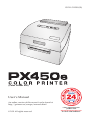
151211-511250-(02)
(Color Printer 450)
User’s Manual
An online version of this manual can be found at
http://primera.eu/europe/manuals.html
© 2011 All rights reserved
*after registering your
product. See
www.primerawarranty.com
for terms and conditions.
Notices: The information in this document is subject to change without notice. NO WARRANTY OF
ANY KIND IS MADE WITH REGARD TO THIS MATERIAL, INCLUDING, BUT NOT LIMITED TO,
THE IMPLIED WARRANTIES OF MERCHANTABILITY AND FITNESS FOR A PARTICULAR
PURPOSE. No liability is assumed for errors contained herein or for incidental or consequential
damages in connection with the furnishing, performance, or use of this material. This document
contains proprietary information that is protected by copyright. All rights are reserved. No part of
this document may be photocopied, reproduced, or translated into another language without prior
written consent.
Trademark Acknowledgments: Windows is a registered trademark of Microsoft Corporation.
All other trademarks are the property of their respective owners.
Printing History
Edition 2.0, #151211, Copyright 2011, All rights reserved.
FCC Compliance Statement: This device complies with part 15 of the FCC rules. Operation is subject
to the following two conditions: (1) this device may not cause harmful interference, and (2) this device
must accept any interference received, including interference that may cause undesired operation.
For Users in the United States: This product is intended to be supplied by a UL listed Direct Plug-In
Power Supply marked "Class 2"or a UL listed ITE Power Supply marked "LPS" with output rated
12VDC, 4.5A or higher. This equipment has been tested and found to comply with the limits for a
Class A digital device, pursuant to Part 15 of the FCC Rules. In a domestic environment this product
may cause radio interference, in which case the user may be required to take adequate measures. This
equipment generates, uses, and can radiate radio frequency energy and, if not installed and used in
accordance with the instructions, may cause harmful interference to radio communications. However,
there is no guarantee that interference will not occur in a particular installation. If this equipment does
cause harmful interference to radio or television reception, which can be determined by turning the
equipment off and on, the user is encouraged to try to correct the interference by one or more of the
following measures:
• Re-orient or relocate the receiving antenna.
• Increase the separation between the equipment and receiver.
• Connect the equipment into an outlet on a circuit different from that to which the receiver
is connected.
• Consult the dealer or an experienced radio/TV technician for help.
Use of shielded cables is required to comply with the Class A limits of Part 15 of the FCC Rules.
You are cautioned that any changes or modifications not expressly approved in this manual could
void your authority to operate and/or obtain warranty service for this equipment.
For Users in Canada: This digital apparatus does not exceed the Class A limits for radio noise for
digital apparatus set out on the Radio Interference Regulations of the Canadian Department of
Communications. Le present appareil numerique n'emet pas de bruits radioelectriques depassant
les limites applicables aux appareils numeriques de la class A prescrites dans le Reglement sur le
brouillage radioelectrique edicte par le ministere des Communications du Canada.
CAUTION!
TO PREVENT FIRE OR SHOCK HAZARD, DO NOT EXPOSE THE UNIT TO RAIN OR
MOISTURE. TO REDUCE THE RISK OF ELECTRIC SHOCK, DO NOT REMOVE EXTERIOR
PANELS. NO USER-SERVICEABLE PARTS INSIDE. REFER SERVICING TO QUALIFIED
SERVICE PERSONNEL. OPERATE THE UNIT WITH ONLY THE PROPER ELECTRICAL
SPECIFICATIONS AS LABELED ON THE PRINTER AND AC ADAPTER.
CAUTION!
THIS PRODUCT CONTAINS A LASER DIODE OF A HIGHER CLASS THAN 1. TO ENSURE
CONTINUED SAFETY, DO NOT REMOVE ANY COVERS OR ATTEMPT TO GAIN ACCESS TO
THE INSIDE OF THIS PRODUCT. REFER ALL SERVICING TO QUALIFIED PERSONNEL. THE
FOLLOWING LABEL APPEARS INSIDE YOUR UNIT:
CLASS 1 LASER PRODUCT LASER KLASSE 1
CAUTION!
USE OF CONTROLS OR ADJUSTMENTS OR PERFORMANCE OF PROCEDURES OTHER
THAN THOSE SPECIFIED HEREIN MAY RESULT IN HAZARDOUS RADIATION.
ii
Table of Contents
Section 1: Getting Started ...............................................................................1
A. Choosing a Good Location ................................................................1
B. Unpacking and Inspection.................................................................2
C. Identifying the Parts ...........................................................................3
D. Computer Specifications ....................................................................4
Section 2: Hardware and Software Setup....................................................5
A. Connecting Power...............................................................................5
B. Connecting the USB Cable/Installing the Printer Driver .................5
C. Installing Media ..................................................................................7
D. Installing the Ink Cartridge .............................................................10
E. Aligning the Ink Cartridge ..............................................................11
Section 3: Using the Integrated Cutter.......................................................12
Section 4: Printer Settings.............................................................................14
A. PC Printer Driver Settings ...............................................................14
Section 5: Advanced Configuration Settings............................................21
Section 6: Troubleshooting ...........................................................................25
A. Solving Registration Problems........................................................25
B. Clearing a Media Jam.......................................................................28
C. Cleaning the Printer..........................................................................28
D. Cleaning the Ink Cartridge..............................................................29
E. Technical Support .............................................................................29
Section 7: Media and Roll Specifications..................................................30
Section 8: Technical Specifications .............................................................32
Index .................................................................................................................33
iii
iv
Section 1: Getting Started
THANK YOU…
...for choosing an PX450e Color Point-of-Sale Printer. The
PX450e Printer will print full color point of sale images quickly
and reliably.
This User's Manual is your complete step-by-step guide to
quickly and easily setting up and printing with your new
Printer!
A. CHOOSING A GOOD LOCATION
•
•
•
•
Place the printer on a flat surface in a location with
adequate air circulation to prevent internal heat build-up.
Do not place the printer near heat sources such as radiators
or air ducts, or in a place subject to direct sunlight,
excessive dust, mechanical vibration or shock.
Allow for adequate clearance in front of the printer to
accommodate the printed paper stock as it is leaving the
printer to avoid the possibility of binding or jamming of
the media.
Allow for adequate overhead clearance for opening the
top cover to allow easy access to the media and ink
cartridge.
Getting Started 1
B. UNPACKING AND INSPECTION
While unpacking your printer, inspect the carton to ensure
that no damage has occurred during shipping. Make sure
that all supplied accessories are included with your unit. The
following items should be included:
•
•
•
•
•
•
•
•
Printer
Power Adapter
Separate Power Cord
USB Cable
Software Installer CD
Color Ink Cartridge
Starter roll of continuous paper stock
This manual and other printed information
Save the carton and packing materials. They will come in handy when
transporting the printer.
2 Getting Started
C. IDENTIFYING THE PARTS
This illustration shows the front of the printer with its control
buttons and LED indicator lights.
Media Sensor Bar
Power LED
Ink LED
Top Cover
Ink Button
Cutter
Load/Feed Button
Unload Button
The Power LED indicates that the printer is on and ready to
receive print jobs.
The Ink LED will illuminate when a cartridge has 10% or less
of its ink remaining.
The Ink Button moves the print carriage to the center of the
printer so you can easily change the cartridge.
The Load/Feed Button is pressed in order to load media or
form feed the paper stock through the printer.
The Unload Button will unload the installed media by
reversing it through the printer. Make sure to tear off the
printed media before pressing the Unload Button.
Getting Started 3
This illustration shows the input ports and power switch found
on the rear panel of the printer.
Fan-fold Media Slot
Power Switch
USB Port
Power Input Port
D. COMPUTER SPECIFICATIONS
Minimum PC Specifications
For optimal printing speed you must have a PC with the
following minimum specifications:
•
•
•
Pentium IV processor
512 MB of RAM
5 GB of free hard drive space
4 Getting Started
Section 2: Hardware and Software
Setup
A. CONNECTING POWER
1.
Locate the Power Adapter
supplied with your printer.
2.
Plug the Power Adapter into the
Power Input Port on the rear
panel of the printer.
3.
Plug the Power Cord of the
adapter into an available wall
outlet or surge protecting power
strip. Once the Power Cord is connected, the printer can be
switched on and off using the Power Switch.
B. CONNECTING THE USB CABLE / INSTALLING THE
PRINTER DRIVER
1.
Place the installer CD in the computer's CD/DVD drive. Ignore
any autorun/autoplay prompt
that appears.
2.
Connect the printer to your PC.
3.
After a few moments, Windows⎪
will tell you it has found new
hardware and is looking for software to install it.
Hardware and Software Settings 5
4.
Select "Install the software automatically" and click Next.
You may see a notice like the one shown here stating that
the Printer has not passed Windows Logo Testing. Click
Continue Anyway to continue installing the printer driver
for your Printer.
6 Hardware and Software Settings
C. INSTALLING MEDIA
Media Guide
Your printer will utilize a
wide variety of continuous
media. Most inkjet receptive
media within the provided
size specifications will work
in your printer. Primera
carries a variety of media
that has been converted
and is ready for use with
your printer.
1.
Open the Top Cover.
2.
Pull the spring-loaded Media Guide out far enough to fit
the roll of media.
Important Note: Using die-cut label stock is not recommended.
3.
Remove any shipping tape from your media roll to ensure
that it can unroll freely, making certain that no adhesive
portion is exposed. It is important to note that any exposed
adhesive surface can attach itself the inner workings of the
print mechanism and cause a media jam.
Roll Core Holders
Hardware and Software Settings 7
4.
Place the media roll between the Roll Core Holders and
release the spring-loaded Media Guide to hold the roll.
The Roll Core Holders allow the roll to move freely.
5.
Place the leading edge of the media between the Throat
Guide and the side of the printer.
Throat Guide
6.
Feed the media further into the printer until it senses the
media and automatically feeds it through the printer.
If the printer fails to feed the media, press the Load/Feed
Button on the front panel while continuing to guide the
media into the printer.
8 Hardware and Software Settings
For narrow media it may be necessary to adjust the media
sensor position. The scale on the Media Sensor Bar represents
the distance from the sensor to the left edge of the media.
Adjust the sensor to be roughly centered on the media. The
media sensor is used to automatically detect when a label is
fed into the printer and to stop the printer when the media is
depleted.
in.
mm
0.5
12.7
1.0
25.4
1.5
38.1
2.0
50.8
Media Sensor Bar
To adjust the sensor position, use a pen to move the slide bar to
the correct postion.
Hardware and Software Settings 9
D. INSTALLING THE INK CARTRIDGE
Your printer has a built-in ink tracking system. This system is
designed to warn you if your ink cartridge is low on ink. This
ensures your labels will print properly.
In order to make this system work properly, the Ink Cartridge
must be changed using the procedure listed below. Failure
to follow this procedure could result in inaccurate ink level
tracking and could cause your print quality to suffer.
When you encounter a low ink condition the Ink LED will flash
and a low ink warning message will automatically print. The
Ink Cartridge is changed as follows:
1.
Open the Top Cover of the printer.
2.
Press the Ink Button to move the Cartridge Holder to the
center of the print area.
3.
Press the Cartridge Cover Release to open the Cartridge
Holder.
4.
Remove the new Ink Cartridge from its
packaging. Be sure to remove the protective
tape covering the copper contacts.
5.
Install the Ink Cartridge copper end first.
6.
Push the Cartridge Cover downward until it snaps in place.
7.
Press the Ink Button again.
The Ink LED will turn off and the printer is now ready to print.
10 Hardware and Software Settings
E. ALIGNING THE INK CARTRIDGE
Cartridge alignment is optional and is only necessary if you
would like to improve print quality. Cartridge alignment will
align the Color Ink Cartridge for bidirectional printing and
calibrate the printer to each individual cartridge. Align the
cartridge via the printer settings which are described in
Section 4.
For alignment you will need to have media installed that is
equal to or larger than 3" (101.6mm) wide. If your stock does
not meet this requirement follow the steps below:
a.
Unload your current stock by pressing the Unload Button.
The printer will reverse the media so that it can be
removed from the printer.
b
Now send the alignment via the printer preferences area.
It is important that you send the alignment with no media
installed.
c.
Cut a 8.5" x 11" sheet of paper in half lengthwise so that it
is no wider than 4.25”. Push the paper into the feed area.
Once the printer senses the page it will pull it into place.
You must feed the test sheet of paper into the printer after
the alignment print has been sent to the printer otherwise
it will feed the sheet right through the printer without
printing.
d. The printer will print the alignment test and scan it into
memory. Once the alignment is complete you will see a
confirmation screen on your monitor. Click OK.
Hardware and Software Settings 11
Section 3: Using the Integrated Cutter
The printer has an integrated cutter that is designed to cut
media on a continuous roll. By default the printer will automatically cut the media immediately after the image is printed.
You can adjust when the cutter will cut and the cut position by
accessing the settings in the Printer Preferences.
WARNING: The cutter is not designed to cut through adhesive-backed
media such as labels. While it will cut through most adhesive-backed
media, continued use in this manner will cause premature wear on
the cutter blade and excessive adhesive build-up.
To Find Driver Settings:
Click the Start button; choose Printers and Faxes. Right-click
on the Color Label 450 icon and select Printing Preferences
from the drop-down menu.
Adjust the Following Settings:
Output Mode:
Do not Present. The media does not move after the last image
is printed. This means that part of the last image printed is
still in the printer. The media is not cut in this mode.
Cut after No Activity. Use this setting to print multiple
images/pages/documents consecutively and then cut after all
have been printed. The time to wait before cutting can be
adjusted using the Present Delay key in the configuration
INI file. See Section 5.
Cut Every Label (default setting). This mode presents and cuts
the printed image after every print. Use for standard one-off
printing.
12 Using the Integrated Cutter
Offsets - Cut Position:
With this setting you can fine-tune the cut position after the
image prints. Increase this value to move the media further out
before the cut; decrease this value to eject the stock less before
the cut. The unit of measure is is 0.1mm.
Note: Every one-hundred cuts the cutter will cut twice (one cut, one cycle)
to clean the blades.
Note: If you are using Primera wristband stock the default Cut Position is
set so that you do not cut through the adhesive portion of the the
stock. If you adjust the Cut Position be make sure that it is not
adjusted so that it cuts through the adhesive.
Using the Integrated Cutter 13
Section 4: Printer Settings
A. PC PRINTER DRIVER SETTINGS
Refer to the following steps to change or verify your default
printer driver preferences.
To Find Driver Settings:
Click the Start button; choose Printers and Faxes. Right-click
on the Color Label 450 icon and select Printing Preferences
from the drop-down menu.
The preferences screen will appear.
14 Printer Settings
Paper Size
This setting allows you to set the height and width of your
print image in .01" or .1mm increments.
Orientation
There are two settings for orientation, Portrait and Landscape.
If your text and graphics print left to right or as shown on the
screen, select portrait . If you wish your printing to rotate 90
degrees from what you see on the screen so it is printing
horizontally, select landscape as your orientation. Remember,
this does not automatically change the width and height of the
Media.
Portrait
Landscape
Print Quality
There are four levels of print quality in the driver. The lower
the quality, the faster the print. Quality 1 provides the fastest
print available while Quality 4 provides the best quality. It is
recommended that you experiment with the different levels
when designing your print image to find a good balance
between print quality and print speed. Quality 1 is the default
setting that is recommended for fastest printing.
Color Matching
Best for Graphics mode is best used for graphical images
where accurate color reproduction is not as essential. Images
printed in this mode will look more vibrant because more ink
is being used to produce them. However, printing images of
people may produce skin tones that have a reddish tint.
Printer Settings 15
Best for Photos mode is best used for photographic images
where accurate color reproduction is essential. Images printed
in this mode will look lighter than those printed in Photo
mode. Skin tones especially will look more natural in this
mode.
NOTE: Exact color matching of the printed image to the screen may not be
possible since there are factors that affect this out of the drivers
control. The surface of the media reacts with the ink in the cartridge
to produce the color. For this reason, when printing the same image
to different types of media with different surfaces the printed output
can look entirely different.
Ink Saturation
This option controls the amount of ink used when printing an
image. The default setting is 100%, which will provide the
most accurate color matching. If the ink is not drying fast
enough or bleeding, you can decrease the Ink Saturation to
lessen the amount of ink that is applied to the media.
Cartridge Alignment
Cartridge alignment will align the Color Ink Cartridge for
bidirectional printing and calibrate the printer to each
individual cartridge. For best print quality it is recommended
that you align the cartridge. However, cartridge alignment is
not required. To align the cartridge, click on Cartridge
Alignment to reveal a Properties button. Click this button to
start the alignment procedure. You will be prompted to have
media of 3" (101.6mm) wide or larger. If the loaded media
does not meet this requirement, see Section 2E for additional
instructions.
Clean/Change Cartridge & Check Ink Levels
Click this setting to reveal a Properties
button. Click Properties and you will
see the color ink level as well as
buttons allowing you to either clean
or change your ink cartridge. If you
have printed an image you will see an
estimation of prints remaining of the
last label.
16 Printer Settings
This number can also be used to calculate total number of
prints you can get from one cartridge and also ink cost per
label. Use the following formula:
Prints Remaining X 100 / Percentage of Ink Remaining = Total
Prints from a Full Cartridge.
In the example above 300 X 100 / 83 = 361 prints from a full
cartridge. Use the cost of the ink cartridge divided by the total
labels from a full cartridge to receive cost per print.
Clean/Purge
If it has been more than 48 hours since your last print or if your
print quality has deteriorated with bands or lines it is
recommended that you clean the cartridge. This is done
by clicking the Clean/Purge button. The Clean Purge is
performed as follows:
Note: You will be prompted to load media of 4"x 4" (101.6 mm x 101.6mm)
or larger, into the printer. If you have stock of this size
or larger, simply click OK. If not see Section 2I for instructions on
loading a test sheet to complete the purge print.
The printer will print a purge pattern where swaths of each
color are printed to clean the jets of the cartridge. A series of
diagonal lines are printed in each color of the cartridge. By
examining this pattern you can tell if the cartridge is firing all
jets or if the cartridge is dirty and requires further cleaning.
While the blocks of color may not print solidly, it is important
that the diagonal lines be continuous. Repeat this process until
all diagonal lines print without breaks.
Change Cartridge
Click the Change Cartridge button to move the cartridge into
position for easy access for replacement. For more information
on this, see Section 2D.
Printer Settings 17
Details/Print Counter
Clicking on the Details button will allow you to view
information about printer settings stored in the printer.
There is also a Print Counter in the details window to help
you count the number of prints printed since the last time it
was reset. Click Reset Counter to set the counter to zero.
The Restore Factory Defaults button will restore the printer settings displayed on the details window to factory calibrated
defaults.
Sensor Type
Sensor Type refers to the method the printer will use to detect
the print starting position for each image. If you are using
standard die-cut labels or Through-hole label material where
holes in the stock are used for alignment purposes, use the
Die-Cut/Thru-Hole setting. Use Reflective for timing mark
sensing label material where a pre-printed line on the back of
the media indicates the break between labels. If you have
continuous stock with no die-cut, reflective mark, or holes, set
the sensor type to Continuous Feed. This will turn off the
media sensor during printing. This is the default setting.
Important Note:
18 Printer Settings
Die-cut media is not recommended.
Output Mode
Do not present. The media does not move after the last image
is printed. This means that part of the last image printed is still
in the printer. The media is not cut.
Cut after No Activity. Use this setting to print multiple
images/pages/documents consecutively and then cut after all
have been printed. The time to wait before cutting can be
adjusted using the Present Delay key in the configuration ini
file. See Section 5.
Cut Every Label. This modes presents and cuts the printed
image after every print. Use for standard one-off printing.
(default setting).
Enable Bi-di Printing
This setting defaults to Yes for fastest printing. When enabled
you will be required to perform an alignment print after a new
cartridge is installed.
Offsets
If your image is printing horizontally or vertically offset
(printing on the liner or with white space left on the label) use
these offset setting to adjust the position of the print on the
label. Click Offsets... to reveal the properties button. Click
Properties. The following screen will appear. Refer to the
diagram to determine which direction to move the image,
tear off position or cut position.
Printer Settings 19
Left Margin Offset
This will be factory calibrated. If fine-tuning is needed,
increase this setting to move the image right on the media;
decrease this setting to move the image to the left on the
media. The unit of measure is 0.1mm.
Top of Form (TOF)
This setting allows you to fine-tune the image starting position
on your media. This will be factory calibrated. If fine tuning is
needed, increase this value to move the image down on the
media. Decrease this value to move the image up the media.
The unit of measure is 0.1mm.
Click the Test button to send a test
print to the printer that will help
you adjust the TOF and Left Margin
Offset. The printer will print the
pattern shown. Adjust the values
so that both black bars print on the
label with no white space on the
label and no ink on the metal plate
supporting the media.
+
-
LEFT OFFSET
(10 units)
1.0 mm
TOF
+
-
Cut Position
With this setting you can fine tune the cut position after the
image prints. Increase this value to move the paper further out
before the cut; decrease this value to eject the media less before
the cut. The unit of measure is is 0.1mm.
20 Printer Settings
Section 5. Advanced Configuration
Settings
When the printer driver is installed in Section 2, a configuration
INI file is also installed. You can edit the settings in the file to
control some advanced printer functions.
Configuration settings are located here:
For Windows XP:
C:\Documents and Settings\All Users\Application
Data\PTI\Drivers\Color Label 450\pt_lp450.ini
For Windows Vista:
C:\ProgramData\PTI\Drivers\Color Label 450\pt_lp450.ini
Many of these settings will increase or decrease the time it
takes to print the media. Explanations of each are included
within the ini file.
Below is copy of the relevant contents of the configuration file:
[settings]
;************************************************
; BLOOM COMPENSATION
; #Black pixels to remove
BloomComp = 2
; Override for ink capacity values (in M)
;ColorSpits = 515
ColorSpits = 463
BlackSpits = 400
PigBlackSpits = 600
; DEBUGGING
;
; turn debugging ON (1) or OFF (0) -- default is OFF if not specified
DebugOn = 0
; AMOUNT OF DEBUG INFO
; LEVEL = 0 through 6 (lower numbers give more debug info)
Advanced Configuration Settings 21
; 0 = DBGLVL_ZERO
; 1 = DBGLVL_TRACE
; 2 = DBGLVL_DUMP
; 3 = DBGLVL_INFORM (default if not specified)
; 4 = DBGLVL_WARNING
; 5 = DBGLVL_ERROR
; 6 = DBGLVL_FATAL
DebugThreshold = 3
; Number of passes override
;For 600x600 NumPasses can be: 1,2,3,4,6,8,12,16
; NOTE: this only works for Quality 1
Slot1NumPassesOverride=1
Slot2NumPassesOverride=1
; Carrier speed override
; CarrierSpeed can be 0-40
;Slot1CarrierSpeed=30
;Slot2CarrierSpeed=30
; Bypass the alignment required warning?
; 0 = don't bypass the warning (DEFAULT) 1= bypass the warning
; NOTES:
;
1. This only works if cartridge setting is set to Color only or Black only
;
2. USE AT YOUR OWN RISK - BYPASSING ALIGNMENT MAY NOT PROVIDE OPTIMUM PRINT QUALITY
;
;
(for best print quality you should align after changing cartridges).
3. The warning will still show up after changing the cartridge, but you can Cancel. The
warning will not be given when printing.
BypassAlignWarning=1
; This value sets the delay before presenting the label after no activity
; Units are 0.1 seconds (e.g. value of 10 will cause a delay of 1 second before presenting the
label)
; This only applies when the printer output mode is "Present after no activity"
PresentDelay = 10
; This value sets the behavior of the horizontal scan. This scan attempts to keep the left margin
consistent
; even if the label moves horizontally.
22 Advanced Configuration Settings
; 0 = disable horizontal scan
; 1 = enable scan at the end of each print (fast but may not be as accurate - if printing is full
bleed or too close the the
;
;
edge of the label then it may scan at the beginning of the next label).
NOTE: when Output mode is set to Present or Cut then it will always scan at the beginning
of the first label
; 2 = enable scan at beginning of each print (slower but might be more accurate)
; 255 = no change from previously used setting
HorizontalScan=1
; Extra maintenance
; 0 = Idle Time maintenance
; 1 = Job Start (uncap) maintenance
; 2 = Threshold maintenance
; 3 = POR maintenance
; 4 = Single wipe only (no spits)
; 5 = Install maintenance
;
; You can specify that extra maintenance be done at the beginning of each print with this setting
; This can be utilized if the prints tend to be light at the beginning of the print
;
;ExtraMaintenance = 1
; Output mode override - for PX450
; 0 = do not present/cut the label
; 1 = Cut after no activity (using PresentDelay value)
; 2 = Cut every label
; 5 = No change in output mode (this is the default value)
OutputMode=5
;; Feed length of print after cutting
;; Set to 1 to enable (default ), 0 to disable
;; Doing this may help when printing labels > 3 inches and when running at faster speeds (see
below)
FeedAfterCut=1
;; TOF Sensor Type override
;; You can override the value of the TOF sensor setting in the printer with this key
;; 0 = Through Mode (e.g. Die Cut stock)
Advanced Configuration Settings 23
;; 1 = Reflective Mode (e.g. Black mark on back)
;; 2 = Continous Stock (don't use sensor)
;; 255 = Use printer setting (this is default)
TOF_Sensor = 255
; Flash frequency - for LX400
; Number of times per second to blink the LED
; (starts at beginning of RIP and stops when data starts getting sent to printer)
; Purpose: indicates that data is being ripped and printer is waiting
LEDFlashFrequency=3
; //// Feed Speed control ////
;;; Faster Speed set to 55
;;; Slower Speed set to 35 (default)
ForwardSpeed=55
PrintSpeed=55
ReverseSpeed=55
; /// POS Applications ///
; Send an "Ink Low" Print automatically when the ink is low.
; The print will be sent after every regular print - until the ink is not low anymore
; Set to 1 to enable, 0 to disable
PrintInkLowWarning=1
; //// Show Error Messages ////
; Whether or not to show error message boxes
; 0 = don't show, 1 = show (default)
SHOW_UI=0
; //// Maintenance during Idle ////
;;; CapTime = Number of seconds before the cartridge goes back home (after printing)
;;; For PX450 the Default = 30 minutes = 1800
CapTime = 1800
;;; PenIdleMaintainTime = Number of 1/2 seconds between maintenance while idle (and not in
home position)
;;; For PX450 the Default = 2 minutes = 240
PenIdleMaintainTime = 240
24 Advanced Configuration Settings
Section 6: Troubleshooting
A. SOLVING REGISTRATION PROBLEMS
Image is Vertically Offset
When printing on media other than continuous, the PX450e
decides where to start printing by detecting the start of a diecut label, detecting a black mark on the back or detecting a
thru-hole that corresponds to the start of the label.
The following items can cause the media sensor to improperly
detect the start of a label:
1.
TOF Offset. TOF stands for Top of Form and this setting
allows you to fine tune the alignment of your printing on
your paper stock. This will be factory calibrated. If fine
tuning is needed, increase this setting to move the image
down on the media; decrease this setting to move the
image up on the media. The unit of measure is 0.1mm.
To access go to Start - Control Panel - Printers and Faxes Right click Color Label 450 - Choose Printing Preferences Select Offsets. See image in the dialog below for a
graphical example.
Troubleshooting 25
2.
Nonstandard / Non-translucent Backing Material. If you
have purchased label stock from someone other than
Primera, test the unit with the label sample material that
came with the unit. If it prints correctly, your paper stock
may not be compatible. The media sensor needs to see the
difference between a label and a backing material by
seeing through the paper stock for light variations. If it can
not see through the label, problems will arise. If you must
use this type of backing, try paper stock that has a black
mark on the back to show where the label begins. You
will need to change the Sensor Type setting in the driver
preferences to Reflective.
3.
Improper Label Gap Distance. See Section 6 for label
specifications.
4.
Page Size is Bigger than Paper Stock Size. If the page size
set in the driver is larger than the actual paper stock, ink
will be printed on the gaps and the sensor will start
looking for a gap too late. This can cause label skipping
or inconsistent print starting points.
5.
Portrait / Landscape. If the Portrait / Landscape setting
does not correspond to the paper stock installed this will
also cause the printer to print over the gap and onto the
next label. Make sure this is set correctly.
6.
Sensor Position. Circular, nonstandard label shapes or
multiple labels across will require precise adjustment of
the label sensor.
Image is Printing Horizontally Offset.
Two printer driver settings can affect this issue.
Left Margin Offset. This adjustment is found in the printer
preferences area of the printer driver. If you see white space on
the right (printer’s left) side of the media and overlap on the
opposite side, decrease the numbe. (Negative numbers are
allowed.) If you see white space on the left (printers right)
side of the media and overlap on the opposite side, increase
the number.
26 Troubleshooting
Note: Often times a space on the right (printer’s left) side indicates a
margin around the media that is not being accounted for. The printer
is factory calibrated for a 2mm margin. A larger margin around the
media will cause a right (printer’s left) side space.
Page Size. Often the page size is not large enough for the
media. If this is the case you may see white space on the right
(printer’s left) side of the the media and no image over lap on
the opposite side. This indicates that the page size needs to be
increased. Increase the page size enough through the printer
preferences to cover the media.
Troubleshooting 27
B. CLEARING A MEDIA JAM
If there is a media jam in the printer mechanism, first attempt
to remove the jam by opening the Top Cover and removing the
jam from the printer output area.
If the jam can not be located, it is possible to remove a cover
over the printer input area. Pull on the center of the cover as
shown below to release the tabs on the sides.
To prevent future jams, use rubbing alcohol to remove any
adhesive left in the printer feed area.
PULL
C. CLEANING THE PRINTER
If any ink has gotten onto the printer casing itself, the case of
the printer can be cleaned with an ammonia-based window
cleaner and a lint-free cloth.
Over time, ink overspray may gather at the base of the printer.
The printer uses a vacuum system to gather most of this ink
on a series of saturation pads. Eventually, these pads may
need to be replaced. Contact Tech Support to determine if
pad replacement is necessary.
28 Troubleshooting
D. CLEANING THE INK CARTRIDGE
It may be necessary to clean the ink cartridge nozzles if you
notice reduced print quality, or if you suspect an cartridge
nozzle has become slightly dried-out or clogged. If you are
having print quality problems, follow the steps below:
1.
Remove the print cartridge.
2.
Moisten a lint-free cloth with water.
3.
Hold the cloth against the nozzles for three seconds.
This will “wick” some additional
ink onto the damp cloth.
4.
Wipe in one direction only.
5.
Repeat the process.
E. TECHNICAL SUPPORT
If you have difficulties in operating your Printer, the procedures
in this manual and the software User's Guide should, in most
cases, solve the problem. If you still have difficulty, contact the
technical support number using one of the methods listed
below.
Source
Location
Primera Knowledge Base
www.primera.com/knowledgebase.html
NiceLabel Software Help files
Open the software. Click on the Help
Menu - Contents
Email Support
[email protected]
Chat Support
www.primera.com/knowledgebase.html
Phone Support
+49 (0)611 92777-0 (Mon - Thu 9 a.m. - 5 p.m,
Fri 9 a.m. - 3 p.m. CET)
Troubleshooting 29
Section 7: Media and Roll
Specifications
Important Note:
Printing labels is not recommended as this printer
was designed for continuous media. However, since
the printer is capable of sensing labels, the following
information that is specific to labels is provided with
no representations regarding reliability.
Label Sensing Methods
Label Width
Liner/Media Width
Gap Between
Labels
Method 1: Label
Gap Sensing
Label Height
Method 2: Thru-Hole
Sensing
Width of Opening
Distance from
edge of label
to edge of liner
Method 3: Reflective/Black
Mark Sensing
(Black Mark must be printed
on back side of label stock)
Black Mark
Width
Note: See table below for Max and Min values in inches and mm..
Max
Min
Label/Print width
4.25" (108mm)
0.75" (19mm)
Liner/Media width
4.25" (108mm)
1" (25.4mm)
Label height/length
24" (609.6mm)
0.75" (19mm)
Gap between labels
0.75" (19mm)
0.10” (2.5mm)
Width of thru-hole
opening
0.5" (12.7mm)
0.375” (9.5mm)
30 Media and Roll Specifications
Max
Min
Distance from edge of
media to edge of
thru-hole
1.90" (48.3mm)
0.20" (5.1mm)
Reflective/Black
Mark Width*
Equal to distance 0.10" (2.5mm)
between labels
Max Outer Diameter (OD) 5.0" (127mm)
N/A
Inner Core Diameter (ID)
see roll specifications below
Stock Thickness
0.006”
(152 micron)
Distance from edge of
label to edge of liner
Printer driver assumes 2 mm gap.
However, this is adjustable via the
left margin offset.
N/A
* The Reflective/Black Mark should be opaque to infared light.
The mark should be between the labels. The end of the mark
should correspond with the beginning of the label.
Roll Specifications
Label Side Out
Roll O.D.
Media Roll
2”
5”
Core I.D.
Core O.D.
Notes:
1. Label height <1.5” requires a 2.00” I.D. x 3.00” O.D. core.
Label height >1.5” requires a 2.00” I.D. x 2.25” O.D. core.
2. Turret glue or 1/2”-wide 3M 928 double-sided removable tape must be
used to attach stock to core. Removable tape must be positioned across
full width of core. Other types of tape are not allowed.
3. End face of liner must align with end of core on both sides within 0.030”.
(Core width should be the same as liner width.)
4. Masking tape or equivalent may be used to secure label stock to outside of roll.
Media and Roll Specifications 31
Section 8: Technical Specifications
Inkjet
4800 x 1200 dpi, 1200 x 1200 dpi, 600 x 600 dpi
#53376 Color (CMY)
16.7 million
Continuous Paper Stock, Roll-fed pressuresensitive labels, roll-fed tags
Media Sensing:
Moveable see-through sensor for die-cut
labels and reflective for tags with black
stripe sensing (not recommended)
Ink Level Warning:
Calculates actual number of prints remaining
based upon ink usage of graphics being
printed (patent-pending)
Indicator Lights:
Power, Ink
Controls:
Ink, Load/Feed, Unload
Operating Systems:
Windows XP/2000/Vista
Data Interface:
USB 1.1/USB 2.0
Minimum System:
Pentium® IV computer or better, 512 MB
RAM, 5 GB free hard drive space,
USB 1.1/2.0 port
Software:
Can also be used with most other popular
Windows-based label design software
programs
Electrical Rating:
12 VDC, 5.0 A
Power Requirements: 100-240 VAC, 50/60 Hz, 60 watts
Certifications:
UL, UL-C, CE, FCC Class A
Weight:
3.2 kg (7.0 lbs.)
Dimensions:
264 mmW x 389 mmD x 180 mmH (closed),
442 mmH (open)
10.4"W x 15.3"D x 7.1"H (closed), 17.4" (open)
Warranty:
Two years after product registration at
www.primerawarranty.com (parts and labor)
Print Method:
Print Resolutions:
Ink Cartridge:
Colors:
Media Types:
32 Technical Specifications
Index
Cartridge Alignment.................................................................11, 16
Cleaning the Ink Cartridge............................................................29
Configuration ......................................................................12, 19, 21
Connecting Power.............................................................................5
Cut Position .....................................................................................20
Cutter ................................................................................................12
Ink Low LED .....................................................................................3
Ink Saturation ..................................................................................16
Installing Media ................................................................................7
Installing the Ink Cartridge ...........................................................10
Installing the Printer Driver ............................................................5
Left Margin Offset ..............................................................20, 26, 31
Load/Feed Button ............................................................................3
Media Sensor Bar ..............................................................................3
Media Specifications.......................................................................30
Offsets ...............................................................................................19
Orientation .......................................................................................15
Power LED .........................................................................................3
Print Counter ...................................................................................18
Print Quality ..............................................................................10, 15
Printer Driver Settings ...................................................................14
Sensor Type ......................................................................................18
Roll Specifications ...........................................................................30
TOF Offset ........................................................................................20
Troubleshooting...............................................................................25
Unload Button ...................................................................................3
Index 33
Printed in the United States of America
P/N 511250