1
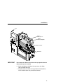
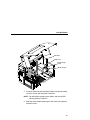
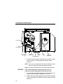
Quick Setup Guide
SL4M™ and T4M™
RFID Smart Label and Thermal Printers
Table of Contents
Introduction ........................................................................... 5
Printer Setup......................................................................... 6
Loading Ribbon And Roll Media ........................................... 8
Load Ribbon................................................................... 9
Load Roll Media ........................................................... 12
Position The Media Sensor Assembly ......................... 15
Controls And Indicators ...................................................... 18
Power Switch ............................................................... 18
Control Panel ............................................................... 18
Run A Barcode Demo Test................................................. 19
Hidden Menus..................................................................... 19
Run The Printer Setup Wizard............................................ 19
Contact Information ............................................................ 20
Printronix Customer Support Center ............................ 20
Printronix Supplies Department ................................... 21
Corporate Offices ......................................................... 21
3
Table of Contents
4
Introduction
Thank you for your purchase of the SL4M RFID Smart Label printer
or T4M thermal printer.
This Quick Setup Guide describes how to set up the printer, load
ribbon and media, and print a test page.
NOTE: This Quick Setup Guide covers both the SL4M and T4M
printers.
The SL4M is a smart label printer. It is equipped with an
RFID encoder and has the “RFID SMART” logo near the
control panel.
The T4M printer does not come equipped with an RFID
encoder, but can be upgraded in the field.
5
Printer Setup
Printer Setup
Front View
Power Switch
1. Place the printer on a flat level surface that allows easy access
to all sides of the printer.
CAUTION
Never operate the printer on its side or upside down.
2. At the front of the printer, set the power switch to O (Off).
6
Rear View
Ethernet Interface
(optional)
IEEE1284 Parallel
Interface
USB Connection
RS-232 Serial
Interface
AC Power
Receptacle
3. At the rear of the printer, connect the desired interface cable to
the appropriate connector and the host computer.
WARNING
Failure to properly ground the printer may result in electric
shock to the operator.
In compliance with international safety standards, this printer
has been equipped with a three-pronged power cord. Do not
use adapter plugs or remove the grounding prong from the
cable plug. If an extension cord is required, ensure that a
three-wire cable with a properly grounded plug is used.
4. Plug the AC power cord into the AC power receptacle.
5. Plug the AC power cord to a grounded (three prong) electrical
outlet of the proper voltage. (Do not turn on the printer yet.)
7
Loading Ribbon And Roll Media
Loading Ribbon And Roll Media
IMPORTANT
8
For best results, use only genuine Printronix supplies. See
“Printronix Supplies Department” on page 21.
CAUTION
DO NOT TOUCH the printhead or the electronic components
under the printhead assembly.
CAUTION
Do not close the pivoting deck without label stock installed
between the printhead and the platen, because debris on the
platen may damage the printhead.
CAUTION
Avoid touching the electrical connectors while setting up the
printer to prevent electrostatic discharge damage. The
discharge of accumulated electrostatic energy can damage or
destroy the printhead or electronic components used in this
printer.
Load Ribbon
Load Ribbon
For direct thermal media (no ribbon required), go to page 12.
Media Cover
Flange
Ribbon
Take-Up Core
Ribbon
Take-Up Spindle
Ribbon
Roll
Ribbon
Supply Spindle
Pivoting
Deck
IMPORTANT
Deck Lock
Lever
Clean the printhead, platen roller, and media sensors every
time you change the ribbon. Refer to the User’s Manual.
1. Raise the media cover.
2. Install the ribbon take-up core on the ribbon take-up spindle.
NOTE: The first ribbon take-up core comes with the printer.
Thereafter, move the empty core from the ribbon supply
spindle to the take-up spindle after the ribbon is used up.
3. Slide the ribbon roll onto the ribbon supply spindle until it is
flush with the flange.
4. Open the pivoting deck by rotating the deck lock lever fully
counterclockwise until the deck swings upward.
9
Loading Ribbon And Roll Media
Ribbon Take-Up
Core
Ribbon
Take-Up Spindle
Ribbon
Supply Spindle
Printhead
Alternate
Ribbon Path
Ribbon
Platen
(not shown)
Ribbon Guide
Roller (2)
5. Thread the end of the ribbon under the ribbon guide rollers,
between the platen (rubber drive roller) and the printhead, and
between the ribbon take-up and supply spindles.
NOTE: Make sure to thread the ribbon behind the ribbon take-up
spindle.
NOTE: The alternate ribbon path is for ribbons that are inked on
the inside.
10
Load Ribbon
Ribbon
Take-up Core
Ribbon
Take-up Spindle
Ribbon Leader
Printhead
IMPORTANT
Never attach the ribbon to the ribbon take-up spindle without a
ribbon take-up core installed.
6. Attach the ribbon to the ribbon take-up core on the ribbon
take-up spindle with tape.
7. Manually rotate the ribbon take-up spindle counterclockwise
until the ribbon leader has passed the printhead.
11
Loading Ribbon And Roll Media
Load Roll Media
Media Cover
Media Hanger
Media Hanger
Guide
IMPORTANT
If you are using direct thermal mode, clean the printhead,
platen roller, and upper and lower media sensors every time
you change the media. Refer to the User’s Manual.
1. Slide the media hanger guide outward to the end of the media
hanger (as shown).
12
Load Roll Media
Side Wall
Media Roll
Media Hanger
Guide
Media Hanger
2. Place the media roll onto the media hanger and slide the media
roll until it is flush with the printer’s side wall.
NOTE: For information regarding smart labels, refer to the RFID
Labeling Reference Manual.
3. Slide the media hanger guide against the media roll to prevent
horizontal travel.
13
Loading Ribbon And Roll Media
Printhead
Platen
(not shown)
Media Sensor
Assembly
Media
Width Guide
Locking
Knob
Media Damper
Media
Alternate
Media Path
4. Thread the media under the media damper, through the media
sensor assembly, and then between the platen and the
printhead.
NOTE: If you have a standard peel, label or liner rewinder, refer to
the User’s Manual for proper threading instructions.
NOTE: The alternate media path is for inside wound label media.
CAUTION
If the media width guide locking knob is too loose or is
removed, the media width guide will fall off the printer.
5. Turn the media width guide locking knob counterclockwise just
enough to slide the media width guide, and no more.
6. Position the media width guide lightly against the outside edge
of the installed media and tighten the locking knob by turning it
clockwise.
14
Position The Media Sensor Assembly
Position The Media Sensor Assembly
Your printer is equipped with a media sensor assembly that detects
the top-of-form position on media with label length indicators (gaps,
notches, holes, or black marks). See page 16.
The media sensor should not be placed in the path of media
features that could cause false gap detection or paper out faults.
Such features are dark pre-printing, rounded die-cut label corners,
vertical gaps associated with side-by-side labels, and extraneous
cut-outs, as shown below.
Position the Gap
Sensor Indicator in
either of the grey
shaded areas.
Vertical Gap and
Rounded Die-cut
Label Corners
Extraneous
Cut-out
Dark Pre-printing
15
Loading Ribbon And Roll Media
Media
(left edge)
Inside Media
Edge Guide
Mark Sensor
Indicator
(both sides)
Gap Sensor
Indicator
(both sides)
Media Sensor
Handle
Media
Media Sensor
Assembly
1. Align the left (inside) edge of the media with the inside media
edge guide.
2. If the label has no special label length indicators, leave the
media sensor assembly in the factory position.
Otherwise, use the media sensor handle to horizontally position
the media sensor assembly so that the sensor indicators
embossed on both of its sides are aligned with the label length
indicators on the media.
Use the Mark Sensor Indicator for media with black marks and
the Gap Sensor Indicator for media with gaps, notches, or
holes.
16
Position The Media Sensor Assembly
Pivoting
Deck
Deck Lock
Lever
3. Rotate the deck lock lever fully clockwise to close the pivoting
deck.
4. If you have an RFID encoder, you may need to adjust the
coupler. (Refer to the RFID Labeling Reference Manual.)
5. Lower the media cover.
17
Controls And Indicators
Controls And Indicators
Power Switch
The power switch is located on the bottom front panel of the printer.
To apply power, place the switch in the | (On) position. When you
first power on the printer, a series of initialization messages
appears on the LCD (Liquid Crystal Display) on the control panel.
To remove power, place the power switch in the O (Off) position.
Control Panel
The control panel is located on the front of the printer and includes
an LCD, indicators, and control keys (buttons).
NOTE: Press the Down
and ↵ (Enter) keys at
the same time to lock
or unlock the ↵ key.
LCD (Liquid
Crystal Display)
Online Indicator
Fault Indicator
Pause Key
Feed Key
Up Key
Enter Key
Menu Key
Cancel Key
Left Key
18
Down Key
Right Key
Control Panel
Run A Barcode Demo Test
Before you send an actual print job, run a bar code demo test:
1. Set the printer power switch to | (On).
2. When ONLINE or OFFLINE displays on the printer’s LCD,
to enter Menu mode.
press
3. Press the Down and ↵ keys at the same time until THE ↵ KEY
IS UNLOCKED displays.
4. Press the Right key until
DIAGNOSTICS displays.
5. Press ↵ to enter the
DIAGNOSTICS menu. The Printer
Tests submenu is selected.
6. Press the Right key until Barcode Demo displays.
7. Press ↵. The printer will go online, and the Barcode Demo test
pattern will start and print two bar codes.
8. If desired, you can run additional printer tests, such as Grey,
Grid, and Checkerboard. See step 2 above to start other tests.
9. If you encounter print quality problems, refer to “Printhead
Adjustments” in the User’s Manual (located on the CD-ROM
included with this book).
Hidden Menus
By default, menu items for advanced users are hidden (they do not
appear in the menu structure). To display these hidden menus, set
Admin User to Enable (in the
PRINTER SETUP menu).
Run The Printer Setup Wizard
Run the Printer Setup Wizard (located on the CD-ROM) to install
the printer drivers and to configure the printer.
19
Contact Information
Contact Information
Printronix Customer Support Center
IMPORTANT
Please have the following information available prior to calling
the Printronix Customer Support Center:
•
•
•
Model number
•
•
•
•
Configuration printout (refer to the User’s Manual)
Serial number (located on the back of the printer)
Installed options (i.e., interface and host type if applicable to the
problem)
Is the problem with a new install or an existing printer?
Description of the problem (be specific)
Good and bad samples that clearly show the problem (faxing or
emailing of these samples may be required)
Americas
(714) 368-2686
Europe, Middle East, and Africa
(31) 24 6489 410
Asia Pacific
(65) 6548 4114
China
(86) 800-999-6836
http://www.printronix.com/support.aspx
20
Printronix Supplies Department
Printronix Supplies Department
For optimal print quality and printhead life, always use Genuine
Printronix Ribbons and Labels. Contact your local Printronix
supplies reseller or contact Printronix at:
Americas
(800) 733-1900
Europe, Middle East, and Africa
33 (0) 1 46 25 19 07
Asia Pacific
(65) 6548 4116
or (65) 6548 4182
China
(86) 400-886-5598
India
(800) 102-7869
http://www.printronix.com/supplies-parts.aspx
Corporate Offices
Printronix, Inc.
15345 Barranca Parkway
Irvine, CA 92618
U.S.A.
Phone: (714) 368-2300
Fax: (714) 368-2600
Printronix Inc.
c/o Printronix Nederland BV
Bijsterhuizen 11-38
6546 AS Nijmegen
The Netherlands
Phone: (31) 24 6489489
Fax: (31) 24 6489499
Printronix Schweiz GmbH
42 Changi South Street 1
Changi South Industrial Estate
Singapore 486763
Phone: (65) 6542 0110
Fax: (65) 6546 1588
21
Contact Information
Printronix Commercial (Shanghai) Co. Ltd
22F, Eton Building East
No.555, Pudong Av.
Shanghai City, 200120, P R China
Phone: (86) 400 886 5598
Fax: (86-21) 5138 0564
Visit the Printronix web site at www.printronix.com
22
Communication Notices
This equipment has been tested and found to comply with the limits for a Class B digital device, pursuant to
Part 15 of the FCC Rules. These limits are designed to provide reasonable protection against harmful
interference in a residential installation. This equipment generates, uses, and can radiate radio frequency
energy and, if not installed and used in accordance with the instructions, may cause harmful interference to
radio communications. However, there is no guarantee that interference will not occur in a particular
installation. If this equipment does cause harmful interference to radio or television reception, which can be
determined by turning the equipment off and on, the user is encouraged to try to correct the interference by
one or more of the following measures:
•
•
•
•
Reorient or relocate the receiving antenna.
Increase the separation between the equipment and receiver.
Connect the equipment into an outlet on a circuit different from that to which the receiver is connected.
Consult the dealer or an experienced radio/TV technician for help.
Unauthorized changes or modifications could void the user’s authority to operate the equipment.
This device complies with part 15 of the FCC Rules. Operation is subject to the following two conditions: (1)
this device may not cause harmful interference, and (2) this device must accept any interference received,
including interference that may cause undesired operation.
Any change or modification to this product voids the user’s authority to operate it per FCC Part 15 Subpart A
Section 15.21 regulations.
This product contains an intentional radiator with the following parameters:
Operating Frequency: 869.525 MHz (AWID 869), 910 to 914 MHz (AWID 910-914),
or 902 to 928 MHz (AWID 915)
Typical RF Power: 100 milliwatts
Maximum RF Power: 700 milliwatts
Printronix SL4M and T4M
Tested To Comply
With FCC Standards
Canada
This Class B digital apparatus complies with Canadian ICES-003 and RSS 210.
Cet appareil numérique de la classe B est conforme à la norme NMB-003 du Canada.
Operation is subject to the following two conditions: (1) this device may not cause interference, and (2) this
device must accept any interference, including interference that may cause undesired operation of the device.
This device has been designed to operate with the antennas listed below, and having a maximum gain of
–12 dBi. Antennas not included in this list or having a gain greater than –12 dBi are strictly prohibited for use
with this device. The required antenna impedance is 50 ohms.
To reduce potential radio interference to other users, the antenna type and its gain should be so chosen that
the equivalent isotropically radiated power (e.i.r.p.) is not more than that permitted for successful
communication.
CE Notice (European Union)
Marking by the CE symbol indicates compliance of this Printronix system to the EMC Directive and the Low
Voltage Directive of the European Union. Such marking is indicative that this Printronix system meets the
following technical standards:
•
EN 300 220-1 (2000), Electromagnetic Compatibility and Radio Spectrum Matters; Short Range Devices;
Radio equipment to be used in the 25 MHz to 1000 MHz frequency range with power levels ranging up to
500 mW.
•
EN 55022 — “Limits and Methods of Measurement of Radio Interference Characteristics of Information
Technology Equipment.”
•
•
EN 55024 — “Electromagnetic Immunity Requirements for Information Technology Equipment”
EN 60950 — “Safety of Information Technology Equipment.”
Printronix cannot accept responsibility for any failure to satisfy the protection requirements resulting from a
non-recommended modification of the product, including the fitting of non-Printronix option cards.
This product has been tested and found to comply with the limits of Class A Information Technology
Equipment according to European standard EN 55022. The limits for Class A equipment were derived for
commercial and industrial environments to provide reasonable protection against interference with licensed
communication devices.
WARNING
This is a Class A product. In a domestic environment this product may
cause radio interference in which case the user may be required to take
adequate measures.
CE Symbol
Declaration Of Conformity
Manufacturer:
Printronix, Inc.
15345 Barranca Parkway
Irvine, CA 92618
U.S.A.
declares that the product:
Product Type:
Information Technology Equipment, Printer
Equipment Class:
Commercial and Light Industrial
Model Numbers:
SL4M, T4M with optional suffixes
Configuration:
serial, parallel, external LAN, Ethernet, Wireless Ethernet, RFID, USB
conforms to the following standards:
Safety:
EN 60950-1: 2001, First Edition
EMC:
ETSI EN 301 489-1
ETSI EN 301 489-3
ETSI EN300 220-3 V1.1.1
EN 55022: 1998 +A1
EN 55024: 1998
EN 61000-4-2
EN 61000-4-3
EN 61000-4-4
EN 61000-4-5
EN 61000-4-6
EN 61000-4-8
EN 61000-4-11
EN 61000-3-2: 2000
EN 61000-3-3: 1995 +A1
and complies with:
The Low Voltage Directive 73/23/EEC and the EMC Directive 89/336/EEC.
The Radio & Telecommunication Terminal Equipment 1999/5/EC.
Taiwan
經型式認證合格之低功率射頻電機,非經許可,公司、商號或使用者均不得擅自變更頻
率、加大功率或變更原設計之特性及功能。
低功率射頻電機之使用不得影響飛航安全及干擾合法通信;經發現有干擾現象時,應立
即停用,並改善至無干擾時方得繼續使用。前項合法通信,指依電信法規定作業之無線
電通信。低功率射頻電機須忍受合法通信或工業、科學及醫療用電波輻射性電機設備之
干擾。
Lithium Battery Warning
If you have the optional real-time clock, then the controller board contains a lithium battery sealed inside the
real-time clock chip. Do not disassemble the chip to replace the battery. Do not dispose of the chip by
incineration. Failure to comply may cause the battery to explode. Contact your local waste agency for the
correct disposal procedure.
Printronix makes no representations or warranties of any kind regarding this material, including, but not limited
to, implied warranties of merchantability and fitness for a particular purpose. Printronix shall not be held
responsible for errors contained herein or any omissions from this material or for any damages, whether
direct, indirect, incidental or consequential, in connection with the furnishing, distribution, performance or use
of this material. The information in this manual is subject to change without notice.
This document contains proprietary information protected by copyright. No part of this document may be
reproduced, copied, translated or incorporated in any other material in any form or by any means, whether
manual, graphic, electronic, mechanical or otherwise, without the prior written consent of Printronix.
COPYRIGHT © 2006, 2012 PRINTRONIX, INC. All rights reserved.
Trademark Acknowledgements
Printronix is a registered trademark of Printronix, Inc.
SL4M and T4M are trademarks of Printronix, Inc.
*251675-001*
251675-001E